EP3609768B1 - Hand-pushed motorized movement device - Google Patents
Hand-pushed motorized movement device Download PDFInfo
- Publication number
- EP3609768B1 EP3609768B1 EP18717705.0A EP18717705A EP3609768B1 EP 3609768 B1 EP3609768 B1 EP 3609768B1 EP 18717705 A EP18717705 A EP 18717705A EP 3609768 B1 EP3609768 B1 EP 3609768B1
- Authority
- EP
- European Patent Office
- Prior art keywords
- module
- slope
- movement device
- user
- wheels
- Prior art date
- Legal status (The legal status is an assumption and is not a legal conclusion. Google has not performed a legal analysis and makes no representation as to the accuracy of the status listed.)
- Active
Links
Images


Classifications
-
- B—PERFORMING OPERATIONS; TRANSPORTING
- B60—VEHICLES IN GENERAL
- B60L—PROPULSION OF ELECTRICALLY-PROPELLED VEHICLES; SUPPLYING ELECTRIC POWER FOR AUXILIARY EQUIPMENT OF ELECTRICALLY-PROPELLED VEHICLES; ELECTRODYNAMIC BRAKE SYSTEMS FOR VEHICLES IN GENERAL; MAGNETIC SUSPENSION OR LEVITATION FOR VEHICLES; MONITORING OPERATING VARIABLES OF ELECTRICALLY-PROPELLED VEHICLES; ELECTRIC SAFETY DEVICES FOR ELECTRICALLY-PROPELLED VEHICLES
- B60L15/00—Methods, circuits, or devices for controlling the traction-motor speed of electrically-propelled vehicles
- B60L15/20—Methods, circuits, or devices for controlling the traction-motor speed of electrically-propelled vehicles for control of the vehicle or its driving motor to achieve a desired performance, e.g. speed, torque, programmed variation of speed
- B60L15/2072—Methods, circuits, or devices for controlling the traction-motor speed of electrically-propelled vehicles for control of the vehicle or its driving motor to achieve a desired performance, e.g. speed, torque, programmed variation of speed for drive off
- B60L15/2081—Methods, circuits, or devices for controlling the traction-motor speed of electrically-propelled vehicles for control of the vehicle or its driving motor to achieve a desired performance, e.g. speed, torque, programmed variation of speed for drive off for drive off on a slope
-
- B—PERFORMING OPERATIONS; TRANSPORTING
- B62—LAND VEHICLES FOR TRAVELLING OTHERWISE THAN ON RAILS
- B62B—HAND-PROPELLED VEHICLES, e.g. HAND CARTS OR PERAMBULATORS; SLEDGES
- B62B5/00—Accessories or details specially adapted for hand carts
- B62B5/0026—Propulsion aids
- B62B5/0069—Control
-
- B—PERFORMING OPERATIONS; TRANSPORTING
- B60—VEHICLES IN GENERAL
- B60L—PROPULSION OF ELECTRICALLY-PROPELLED VEHICLES; SUPPLYING ELECTRIC POWER FOR AUXILIARY EQUIPMENT OF ELECTRICALLY-PROPELLED VEHICLES; ELECTRODYNAMIC BRAKE SYSTEMS FOR VEHICLES IN GENERAL; MAGNETIC SUSPENSION OR LEVITATION FOR VEHICLES; MONITORING OPERATING VARIABLES OF ELECTRICALLY-PROPELLED VEHICLES; ELECTRIC SAFETY DEVICES FOR ELECTRICALLY-PROPELLED VEHICLES
- B60L50/00—Electric propulsion with power supplied within the vehicle
- B60L50/20—Electric propulsion with power supplied within the vehicle using propulsion power generated by humans or animals
-
- B—PERFORMING OPERATIONS; TRANSPORTING
- B62—LAND VEHICLES FOR TRAVELLING OTHERWISE THAN ON RAILS
- B62B—HAND-PROPELLED VEHICLES, e.g. HAND CARTS OR PERAMBULATORS; SLEDGES
- B62B5/00—Accessories or details specially adapted for hand carts
- B62B5/0026—Propulsion aids
- B62B5/0033—Electric motors
- B62B5/0036—Arrangements of motors
- B62B5/0043—One motor drives one wheel
-
- B—PERFORMING OPERATIONS; TRANSPORTING
- B62—LAND VEHICLES FOR TRAVELLING OTHERWISE THAN ON RAILS
- B62B—HAND-PROPELLED VEHICLES, e.g. HAND CARTS OR PERAMBULATORS; SLEDGES
- B62B5/00—Accessories or details specially adapted for hand carts
- B62B5/0026—Propulsion aids
- B62B5/0069—Control
- B62B5/0073—Measuring a force
-
- B—PERFORMING OPERATIONS; TRANSPORTING
- B62—LAND VEHICLES FOR TRAVELLING OTHERWISE THAN ON RAILS
- B62B—HAND-PROPELLED VEHICLES, e.g. HAND CARTS OR PERAMBULATORS; SLEDGES
- B62B5/00—Accessories or details specially adapted for hand carts
- B62B5/06—Hand moving equipment, e.g. handle bars
-
- B—PERFORMING OPERATIONS; TRANSPORTING
- B60—VEHICLES IN GENERAL
- B60L—PROPULSION OF ELECTRICALLY-PROPELLED VEHICLES; SUPPLYING ELECTRIC POWER FOR AUXILIARY EQUIPMENT OF ELECTRICALLY-PROPELLED VEHICLES; ELECTRODYNAMIC BRAKE SYSTEMS FOR VEHICLES IN GENERAL; MAGNETIC SUSPENSION OR LEVITATION FOR VEHICLES; MONITORING OPERATING VARIABLES OF ELECTRICALLY-PROPELLED VEHICLES; ELECTRIC SAFETY DEVICES FOR ELECTRICALLY-PROPELLED VEHICLES
- B60L2200/00—Type of vehicles
- B60L2200/20—Vehicles specially adapted for children, e.g. toy vehicles
-
- B—PERFORMING OPERATIONS; TRANSPORTING
- B60—VEHICLES IN GENERAL
- B60L—PROPULSION OF ELECTRICALLY-PROPELLED VEHICLES; SUPPLYING ELECTRIC POWER FOR AUXILIARY EQUIPMENT OF ELECTRICALLY-PROPELLED VEHICLES; ELECTRODYNAMIC BRAKE SYSTEMS FOR VEHICLES IN GENERAL; MAGNETIC SUSPENSION OR LEVITATION FOR VEHICLES; MONITORING OPERATING VARIABLES OF ELECTRICALLY-PROPELLED VEHICLES; ELECTRIC SAFETY DEVICES FOR ELECTRICALLY-PROPELLED VEHICLES
- B60L2200/00—Type of vehicles
- B60L2200/24—Personal mobility vehicles
-
- B—PERFORMING OPERATIONS; TRANSPORTING
- B60—VEHICLES IN GENERAL
- B60L—PROPULSION OF ELECTRICALLY-PROPELLED VEHICLES; SUPPLYING ELECTRIC POWER FOR AUXILIARY EQUIPMENT OF ELECTRICALLY-PROPELLED VEHICLES; ELECTRODYNAMIC BRAKE SYSTEMS FOR VEHICLES IN GENERAL; MAGNETIC SUSPENSION OR LEVITATION FOR VEHICLES; MONITORING OPERATING VARIABLES OF ELECTRICALLY-PROPELLED VEHICLES; ELECTRIC SAFETY DEVICES FOR ELECTRICALLY-PROPELLED VEHICLES
- B60L2200/00—Type of vehicles
- B60L2200/30—Trolleys
-
- B—PERFORMING OPERATIONS; TRANSPORTING
- B60—VEHICLES IN GENERAL
- B60L—PROPULSION OF ELECTRICALLY-PROPELLED VEHICLES; SUPPLYING ELECTRIC POWER FOR AUXILIARY EQUIPMENT OF ELECTRICALLY-PROPELLED VEHICLES; ELECTRODYNAMIC BRAKE SYSTEMS FOR VEHICLES IN GENERAL; MAGNETIC SUSPENSION OR LEVITATION FOR VEHICLES; MONITORING OPERATING VARIABLES OF ELECTRICALLY-PROPELLED VEHICLES; ELECTRIC SAFETY DEVICES FOR ELECTRICALLY-PROPELLED VEHICLES
- B60L2200/00—Type of vehicles
- B60L2200/34—Wheel chairs
-
- B—PERFORMING OPERATIONS; TRANSPORTING
- B60—VEHICLES IN GENERAL
- B60L—PROPULSION OF ELECTRICALLY-PROPELLED VEHICLES; SUPPLYING ELECTRIC POWER FOR AUXILIARY EQUIPMENT OF ELECTRICALLY-PROPELLED VEHICLES; ELECTRODYNAMIC BRAKE SYSTEMS FOR VEHICLES IN GENERAL; MAGNETIC SUSPENSION OR LEVITATION FOR VEHICLES; MONITORING OPERATING VARIABLES OF ELECTRICALLY-PROPELLED VEHICLES; ELECTRIC SAFETY DEVICES FOR ELECTRICALLY-PROPELLED VEHICLES
- B60L2240/00—Control parameters of input or output; Target parameters
- B60L2240/10—Vehicle control parameters
- B60L2240/14—Acceleration
- B60L2240/16—Acceleration longitudinal
-
- B—PERFORMING OPERATIONS; TRANSPORTING
- B60—VEHICLES IN GENERAL
- B60L—PROPULSION OF ELECTRICALLY-PROPELLED VEHICLES; SUPPLYING ELECTRIC POWER FOR AUXILIARY EQUIPMENT OF ELECTRICALLY-PROPELLED VEHICLES; ELECTRODYNAMIC BRAKE SYSTEMS FOR VEHICLES IN GENERAL; MAGNETIC SUSPENSION OR LEVITATION FOR VEHICLES; MONITORING OPERATING VARIABLES OF ELECTRICALLY-PROPELLED VEHICLES; ELECTRIC SAFETY DEVICES FOR ELECTRICALLY-PROPELLED VEHICLES
- B60L2240/00—Control parameters of input or output; Target parameters
- B60L2240/10—Vehicle control parameters
- B60L2240/14—Acceleration
- B60L2240/18—Acceleration lateral
-
- B—PERFORMING OPERATIONS; TRANSPORTING
- B60—VEHICLES IN GENERAL
- B60L—PROPULSION OF ELECTRICALLY-PROPELLED VEHICLES; SUPPLYING ELECTRIC POWER FOR AUXILIARY EQUIPMENT OF ELECTRICALLY-PROPELLED VEHICLES; ELECTRODYNAMIC BRAKE SYSTEMS FOR VEHICLES IN GENERAL; MAGNETIC SUSPENSION OR LEVITATION FOR VEHICLES; MONITORING OPERATING VARIABLES OF ELECTRICALLY-PROPELLED VEHICLES; ELECTRIC SAFETY DEVICES FOR ELECTRICALLY-PROPELLED VEHICLES
- B60L2240/00—Control parameters of input or output; Target parameters
- B60L2240/10—Vehicle control parameters
- B60L2240/14—Acceleration
- B60L2240/20—Acceleration angular
-
- B—PERFORMING OPERATIONS; TRANSPORTING
- B60—VEHICLES IN GENERAL
- B60L—PROPULSION OF ELECTRICALLY-PROPELLED VEHICLES; SUPPLYING ELECTRIC POWER FOR AUXILIARY EQUIPMENT OF ELECTRICALLY-PROPELLED VEHICLES; ELECTRODYNAMIC BRAKE SYSTEMS FOR VEHICLES IN GENERAL; MAGNETIC SUSPENSION OR LEVITATION FOR VEHICLES; MONITORING OPERATING VARIABLES OF ELECTRICALLY-PROPELLED VEHICLES; ELECTRIC SAFETY DEVICES FOR ELECTRICALLY-PROPELLED VEHICLES
- B60L2240/00—Control parameters of input or output; Target parameters
- B60L2240/10—Vehicle control parameters
- B60L2240/22—Yaw angle
-
- B—PERFORMING OPERATIONS; TRANSPORTING
- B60—VEHICLES IN GENERAL
- B60L—PROPULSION OF ELECTRICALLY-PROPELLED VEHICLES; SUPPLYING ELECTRIC POWER FOR AUXILIARY EQUIPMENT OF ELECTRICALLY-PROPELLED VEHICLES; ELECTRODYNAMIC BRAKE SYSTEMS FOR VEHICLES IN GENERAL; MAGNETIC SUSPENSION OR LEVITATION FOR VEHICLES; MONITORING OPERATING VARIABLES OF ELECTRICALLY-PROPELLED VEHICLES; ELECTRIC SAFETY DEVICES FOR ELECTRICALLY-PROPELLED VEHICLES
- B60L2240/00—Control parameters of input or output; Target parameters
- B60L2240/10—Vehicle control parameters
- B60L2240/24—Steering angle
-
- B—PERFORMING OPERATIONS; TRANSPORTING
- B60—VEHICLES IN GENERAL
- B60L—PROPULSION OF ELECTRICALLY-PROPELLED VEHICLES; SUPPLYING ELECTRIC POWER FOR AUXILIARY EQUIPMENT OF ELECTRICALLY-PROPELLED VEHICLES; ELECTRODYNAMIC BRAKE SYSTEMS FOR VEHICLES IN GENERAL; MAGNETIC SUSPENSION OR LEVITATION FOR VEHICLES; MONITORING OPERATING VARIABLES OF ELECTRICALLY-PROPELLED VEHICLES; ELECTRIC SAFETY DEVICES FOR ELECTRICALLY-PROPELLED VEHICLES
- B60L2240/00—Control parameters of input or output; Target parameters
- B60L2240/10—Vehicle control parameters
- B60L2240/26—Vehicle weight
-
- B—PERFORMING OPERATIONS; TRANSPORTING
- B60—VEHICLES IN GENERAL
- B60L—PROPULSION OF ELECTRICALLY-PROPELLED VEHICLES; SUPPLYING ELECTRIC POWER FOR AUXILIARY EQUIPMENT OF ELECTRICALLY-PROPELLED VEHICLES; ELECTRODYNAMIC BRAKE SYSTEMS FOR VEHICLES IN GENERAL; MAGNETIC SUSPENSION OR LEVITATION FOR VEHICLES; MONITORING OPERATING VARIABLES OF ELECTRICALLY-PROPELLED VEHICLES; ELECTRIC SAFETY DEVICES FOR ELECTRICALLY-PROPELLED VEHICLES
- B60L2240/00—Control parameters of input or output; Target parameters
- B60L2240/40—Drive Train control parameters
- B60L2240/42—Drive Train control parameters related to electric machines
- B60L2240/421—Speed
-
- B—PERFORMING OPERATIONS; TRANSPORTING
- B60—VEHICLES IN GENERAL
- B60L—PROPULSION OF ELECTRICALLY-PROPELLED VEHICLES; SUPPLYING ELECTRIC POWER FOR AUXILIARY EQUIPMENT OF ELECTRICALLY-PROPELLED VEHICLES; ELECTRODYNAMIC BRAKE SYSTEMS FOR VEHICLES IN GENERAL; MAGNETIC SUSPENSION OR LEVITATION FOR VEHICLES; MONITORING OPERATING VARIABLES OF ELECTRICALLY-PROPELLED VEHICLES; ELECTRIC SAFETY DEVICES FOR ELECTRICALLY-PROPELLED VEHICLES
- B60L2240/00—Control parameters of input or output; Target parameters
- B60L2240/40—Drive Train control parameters
- B60L2240/46—Drive Train control parameters related to wheels
- B60L2240/461—Speed
-
- B—PERFORMING OPERATIONS; TRANSPORTING
- B60—VEHICLES IN GENERAL
- B60L—PROPULSION OF ELECTRICALLY-PROPELLED VEHICLES; SUPPLYING ELECTRIC POWER FOR AUXILIARY EQUIPMENT OF ELECTRICALLY-PROPELLED VEHICLES; ELECTRODYNAMIC BRAKE SYSTEMS FOR VEHICLES IN GENERAL; MAGNETIC SUSPENSION OR LEVITATION FOR VEHICLES; MONITORING OPERATING VARIABLES OF ELECTRICALLY-PROPELLED VEHICLES; ELECTRIC SAFETY DEVICES FOR ELECTRICALLY-PROPELLED VEHICLES
- B60L2240/00—Control parameters of input or output; Target parameters
- B60L2240/60—Navigation input
- B60L2240/64—Road conditions
- B60L2240/642—Slope of road
-
- B—PERFORMING OPERATIONS; TRANSPORTING
- B60—VEHICLES IN GENERAL
- B60L—PROPULSION OF ELECTRICALLY-PROPELLED VEHICLES; SUPPLYING ELECTRIC POWER FOR AUXILIARY EQUIPMENT OF ELECTRICALLY-PROPELLED VEHICLES; ELECTRODYNAMIC BRAKE SYSTEMS FOR VEHICLES IN GENERAL; MAGNETIC SUSPENSION OR LEVITATION FOR VEHICLES; MONITORING OPERATING VARIABLES OF ELECTRICALLY-PROPELLED VEHICLES; ELECTRIC SAFETY DEVICES FOR ELECTRICALLY-PROPELLED VEHICLES
- B60L2250/00—Driver interactions
- B60L2250/22—Driver interactions by presence detection
-
- B—PERFORMING OPERATIONS; TRANSPORTING
- B62—LAND VEHICLES FOR TRAVELLING OTHERWISE THAN ON RAILS
- B62B—HAND-PROPELLED VEHICLES, e.g. HAND CARTS OR PERAMBULATORS; SLEDGES
- B62B5/00—Accessories or details specially adapted for hand carts
- B62B5/0026—Propulsion aids
- B62B5/0033—Electric motors
- B62B5/0036—Arrangements of motors
- B62B5/0046—One motor drives two wheels
-
- Y—GENERAL TAGGING OF NEW TECHNOLOGICAL DEVELOPMENTS; GENERAL TAGGING OF CROSS-SECTIONAL TECHNOLOGIES SPANNING OVER SEVERAL SECTIONS OF THE IPC; TECHNICAL SUBJECTS COVERED BY FORMER USPC CROSS-REFERENCE ART COLLECTIONS [XRACs] AND DIGESTS
- Y02—TECHNOLOGIES OR APPLICATIONS FOR MITIGATION OR ADAPTATION AGAINST CLIMATE CHANGE
- Y02T—CLIMATE CHANGE MITIGATION TECHNOLOGIES RELATED TO TRANSPORTATION
- Y02T10/00—Road transport of goods or passengers
- Y02T10/60—Other road transportation technologies with climate change mitigation effect
- Y02T10/64—Electric machine technologies in electromobility
-
- Y—GENERAL TAGGING OF NEW TECHNOLOGICAL DEVELOPMENTS; GENERAL TAGGING OF CROSS-SECTIONAL TECHNOLOGIES SPANNING OVER SEVERAL SECTIONS OF THE IPC; TECHNICAL SUBJECTS COVERED BY FORMER USPC CROSS-REFERENCE ART COLLECTIONS [XRACs] AND DIGESTS
- Y02—TECHNOLOGIES OR APPLICATIONS FOR MITIGATION OR ADAPTATION AGAINST CLIMATE CHANGE
- Y02T—CLIMATE CHANGE MITIGATION TECHNOLOGIES RELATED TO TRANSPORTATION
- Y02T10/00—Road transport of goods or passengers
- Y02T10/60—Other road transportation technologies with climate change mitigation effect
- Y02T10/72—Electric energy management in electromobility
-
- Y—GENERAL TAGGING OF NEW TECHNOLOGICAL DEVELOPMENTS; GENERAL TAGGING OF CROSS-SECTIONAL TECHNOLOGIES SPANNING OVER SEVERAL SECTIONS OF THE IPC; TECHNICAL SUBJECTS COVERED BY FORMER USPC CROSS-REFERENCE ART COLLECTIONS [XRACs] AND DIGESTS
- Y02—TECHNOLOGIES OR APPLICATIONS FOR MITIGATION OR ADAPTATION AGAINST CLIMATE CHANGE
- Y02T—CLIMATE CHANGE MITIGATION TECHNOLOGIES RELATED TO TRANSPORTATION
- Y02T90/00—Enabling technologies or technologies with a potential or indirect contribution to GHG emissions mitigation
- Y02T90/10—Technologies relating to charging of electric vehicles
- Y02T90/16—Information or communication technologies improving the operation of electric vehicles
Definitions
- the present invention refers to a motorized movement device, particularly a hand-pushed device, such as for example a baby carriage or cart for transporting goods (e.g. a shopping cart, golf club trolley, airport trolley, suitcase, or similar), disabled person wheelchair, stretcher, walker, hospital bed, or similar.
- a motorized movement device particularly a hand-pushed device, such as for example a baby carriage or cart for transporting goods (e.g. a shopping cart, golf club trolley, airport trolley, suitcase, or similar), disabled person wheelchair, stretcher, walker, hospital bed, or similar.
- Motorized movement devices wherein one or more motors drive wheels as an aid to an user, for example for transporting heavy loads for long distances or along sloped paths, are known in the art.
- the known movement devices generally comprise a command for activating/deactivating the motor.
- a motorized movement device is shown in the attached figures by reference 1.
- the movement device 1 can be of a type discussed in the introductory part of the present description.
- it can be implemented as a baby carriage ( Figure 1a ), a shopping cart ( Figure 1b ), golf club trolley ( Figure 1c ), disabled person wheelchair ( Figure 1d ), suitcase trolley ( Figure 1e ), hospital bed/stretcher ( Figure 1f ), walker ( Figure 1g ), or similar.
- the movement device 1 comprises a frame 101, wheels 102, and one or more handles 103 by means of which the user moves the device itself.
- the movement device 1 comprises suspensions 104 operatively interposed between the frame 101 and at least some of the wheels 102.
- the movement device 1 comprises a first and a second motors (not shown in the figures), independent from each other, each connected to a respective wheel of the device itself.
- the wheels to which the motors are coupled are non-steering wheels and are not coupled to each other.
- the wheels connected to the motors can be the left 102' and right wheels 102", with reference to a baby carriage, or a cart.
- each motor drives a respective wheel and therefore it is possible, by suitably acting on the motors, to provide an assistance not only for advancing the device, but also for steering it, as it will be explained in the following.
- the motors can be coupled to the front wheels of the device (see the disabled person chair of Figure 1d , for example).
- the motors comprise brushless motors.
- Each motor is commanded by a command signal I left , I right , for example a current signal, to which respective driving/resistant torques exerted by the motors themselves correspond.
- the modes by which the command signals of the motors I left , I right are determined will be specifically described in the following.
- To each wheels 102' and 102" can be associated corresponding suspensions 104', 104".
- the movement device 1 further comprises one or more batteries (not shown in the figures) connected to the motors for exchanging power with them.
- the batteries can supply the motors and can be further recharged, by receiving power from the motors when these act as generators.
- the device 1 can comprise an outlet to be connected to an external power source for recharging the batteries.
- the movement device 1 comprises a sensor adapted to detect the presence of the user and to supply a signal representative of such presence.
- the presence detecting sensor can be associated to this latter, for detecting if the user is grasping the rod/grip/handle.
- the user presence detecting sensor can comprise a capacitive sensor or fabric, or can be a photocell, or an infrared sensor.
- the presence detecting sensor can comprise a RFID reader adapted to detect the proximity of a RFID tag, worn by the user for example.
- detecting the presence can be made by wireless systems, such as Bluetooth® or NFC (Near Field Communication).
- the movement device further comprises a module communicating with an external device.
- an external device can be configured to communicate with a user cell phone or smartphone.
- the communication can be wireless, or wired by connecting the external device to a suitable outlet associated to the communication module which, in this case, can be also used for recharging the external device, by supplying it by the beforehand cited batteries.
- a suitable outlet associated to the communication module which, in this case, can be also used for recharging the external device, by supplying it by the beforehand cited batteries.
- the movement device 1 comprises an inertial measuring unit adapted to detect at least the longitudinal acceleration a x , the pitch angular speed ⁇ y and the yaw angular speed ⁇ z of the movement device 1, and to provide signals indicative of the same.
- the movement device 1 comprises sensors for detecting the speeds V left , v right of the wheels 102', 102", to which the first and second motors are associated, configured to supply signals indicative of the same.
- Such speeds v left , v right can be obtained, for example, from detections of the angular speeds of the two wheels 102', 102", from which it is possible to obtain the linear speeds v left , v right by knowing the wheels radiuses.
- the device 1 can comprise sensors for detecting the elongations ⁇ left , ⁇ right of the two suspensions 104' and 104" connected to the wheels 102', 102", to which the motors, configured to supply signals indicative of the same, are associated.
- sensors can comprise rotating potentiometers, linear potentiometers, encoders, strain gauges, or similar, for example.
- the movement device 1 comprises a control unit 2 receiving, at the input, signals from the above described sensors, and which commands the motors based on these, according to hereinbelow described modes. Further, the control unit 2 can command the power exchanges between the batteries and motors and can be connected to the communication module in order to interact with the user external device.
- FIG. 2 shows a block diagram of the control unit 2 of the motorized movement device 1 according to a possible embodiment of the invention.
- the control unit 2 comprises a module 3 for estimating the slope ⁇ , in other words the inclination of the path followed by the movement device 1.
- the slope ⁇ is estimated based on signals representative of the longitudinal acceleration a x , pitch angular speed ⁇ y , and speeds v left , v right of wheels 102' and 102". Estimating the slope ⁇ can be made by algorithms known in the field. With reference to this matter, see, for example: Matteo Corno, Pierfrancesco Spagnol, Sergio M. Savaresi: "Road slope estimation in bicycles without torque measurements.” IFAC Proceedings Volumes 47.3 (2014): 6295-6300 .
- the motorized movement device 1 is provided with suspensions 104', 104" and the elongations ⁇ left , ⁇ right thereof are measured by the beforehand cited sensors, the slope ⁇ estimated by said modes is corrected for taking into account the additional inclination with respect to the ground which is taken by the ascending or descending movement device 1 due to the suspensions deformation. Specifically, once measured the deformation of the suspensions 104', 104" and known the geometrical characteristics of the movement device 1, it is possible to determine the additional inclination (positive or negative) to be subtracted from the estimated slope ⁇ .
- the movement device 1 comprises a module 4 for estimating the longitudinal thrust F x exerted by the user.
- the thrust which is estimated by the module 4, is such to cause an advancement of the device 1 but does not cause it to steer.
- the longitudinal thrust F x is determined based on signals representative of the longitudinal acceleration a x , wheel speeds v left , v right , motor command signals I left , I right , and the slope ⁇ estimated by the module 3.
- the thrust estimating module 4 enables the device to get rid of sensors directly measuring the thrust exerted by the user, e.g. torque or force sensors associated to the handle which, besides determining additional costs, require maintenance, are difficult to be calibrated and are further jeopardized by possible false readings, caused, for example, by objects such as jackets, bags, or similar placed on the handle by the user.
- sensors directly measuring the thrust exerted by the user e.g. torque or force sensors associated to the handle which, besides determining additional costs, require maintenance, are difficult to be calibrated and are further jeopardized by possible false readings, caused, for example, by objects such as jackets, bags, or similar placed on the handle by the user.
- this can be input as a constant value, or can be set from time to time based on commands provided by the user, particularly through his/her own smartphone (the user can input the weight of a kid transported by the carriage, for example).
- the user can select a weight class among predefined weight classes (light, medium, heavy,).
- the motorized movement device 1 comprises a module 5 for estimating the mass M.
- a module 5 for estimating the mass M is possible in the presence of the suspensions 104', 104" and sensors for measuring the elongations thereof.
- the module 5 estimates the mass M based on signals indicative of the elongations ⁇ left , ⁇ right of the suspensions, and of the speeds v left , v right of the wheels, in addition to the slope ⁇ estimated by the module 3.
- the mass M estimating module 5 must estimate the mass M only in the presence of static conditions or semi-static conditions, consequently, the module 5 can be configured so that, if the speeds v left , v right of the wheels, and the accelerations obtainable by deriving these latter are less than predetermined threshold values, the mass M is determined based on a predetermined static map associating the elongations ⁇ left , ⁇ right of the suspensions and the estimated slope ⁇ with the mass M.
- the mass M estimating module 5 comprises a low-pass filter configured to filter the signals indicative of the elongations ⁇ left , ⁇ right of the suspensions in order to filter out the measuring noises.
- the movement device 1 comprises a module 6 for estimate the yaw torque ⁇ Z applied by the user to the device 1 itself.
- the yaw torque ⁇ Z represents a steering maneuver exerted by the user on the device 1.
- the yaw torque estimating module 6 receives, at the input, the signal representing the yaw angular speed ⁇ Z and the mass M estimated by the module 5, if is present.
- said control unit 2 estimates the slope ⁇ , the longitudinal thrust F x , and the yaw torque ⁇ Z .
- Each of these magnitudes represents an effort element exerted by the user of the device 1, which must be decreased by suitably slaving the motors 102', 102".
- the control unit 2 comprises a slope compensating module 7 configured to determine a slope compensating force F slope based on the estimated slope ⁇ and possibly based on the estimated mass M, if the mass estimating module 5 is present. If the module 5 is absent, the mass is considered fixed, according to what was previously described.
- the slope compensating force F slope can be determined for compensating the gravitational force acting on the device 1 due to the slope ⁇ .
- the slope compensating force F slope is a driving force
- the slope compensating force F slope is a braking force
- control unit 2 comprises a module 8 for amplifying the thrust, configured to determine a thrust aiding force F push based on the longitudinal thrust F x exerted by the user, estimated by the module 4.
- the thrust aiding force F push can be simply determined by multiplying the longitudinal thrust F x exerted by the user by a proportional factor.
- proportional factor can be fixed or can be set by the user through his/her own portable device.
- control unit 2 comprises a module 9 for amplifying the yaw torque, configured to determine a steering aiding force F z , based on the yaw torque ⁇ z estimated by the module 6.
- the steering aiding force F z can be simply determined so that it can generate a torque obtained by multiplying the yaw torque ⁇ z by a proportional factor.
- proportional factor can be fixed, or can be set by the user through his/her own portable device.
- the steering aiding force F z is not applied in the same way to the two motors since it must generate a steering torque of the device 1.
- the control unit 2 comprises a torque allocating module 10, configured to determine the command signals I left , I right of the motors and consequently the torques supplied by each of them, based on the slope compensating force F slope , thrust aiding force F push , and steering aiding force F z . Consequently, the motors supply torques such as to exert determined aiding forces.
- the user can act on how much the motors are enslaved by means of the external device, and consequently on the torque generated by them, for taking into account the type of the roadway. For example, the user can select among several predefined types of the roadway (for example: smooth, normal, rough).
- control unit 2 can comprise a module 11 for estimating the effective radiuses R left and R right based on the signals representing the speeds v left , v right of the wheels and the yaw speed ⁇ z .
- the estimate can be obtained when the device moves straight or almost straight and therefore the yaw angular speed ⁇ z is zero or less than a threshold value.
- it is for example possible to determine the least offsets ⁇ left and ⁇ right in order to verify the following condition: v left R left v right R right
- the torque allocating module 10 can correct the command signals I left , I right , calculated by assuming the radiuses of the two wheels are equal, so that the torques generated by the motors offset the asymmetry caused by different radiuses of the wheels.
- the module 11 for estimating the effective radiuses R left and R right is, more generally, capable of compensating conditions causing a drift. Apart from the differences between the radiuses of the wheels caused by wear or manufacturing errors, such condition can be verified for example in the following cases: friction differences between the wheels on the two sides of the vehicle (for example if one of the two wheels is partially deflated), differences in the roadway between one side and the other of the device, asymmetric thrust exerted by the user.
- a further asymmetry, which can be found, can be determined by the positions of the transported loads. This aspect can be monitored by the suspension elongation sensors, if present, and can be consequently compensated by the torque allocating module.
- the torque allocating module 10 further receives, at the input, the signal representing the presence of the user (U), from the associated presence sensor indicated by 12 in Figure 2 .
- the torque allocating module 10 is configured to generate the motor commanding signals I left , I right only if the user presence sensor detects the presence thereof. In other words, if the presence of the user is not detected, the motors are deactivated, and the device becomes a completely passive system. Consequently, the device is prevented from being inadvertently actuated even though the user is present.
- the control unit 2 comprises a module 13 for identifying a maneuver for getting past an obstacle.
- a module 13 for identifying a maneuver for getting past an obstacle In this regard, it is considered a case shown in Figure 3 , wherein the user moving the baby carriage comes across a step. Under such condition, the typical maneuver performed by user is to raise the front wheels by applying a downwardly directed force F user , then, with the front wheels still raised, he/she longitudinally pushes the carriage for getting past the step. Under such condition, the carriage is tilted and consequently the slope estimating module 3 estimates an erroneous slope ⁇ , because is not determined by the slope of the path, but by a maneuver performed by the user.
- the torque allocating module 10 is required to neglect the slope compensating force F slope , in order to prevent the motors from generating a torque not according to the real condition under which the device is subjected, in other words not a sloping road but an obstacle present along the path.
- the module 13 identifying a maneuver for getting past an obstacle is configured to identify the presence of an obstacle based on the slope ⁇ estimated by the module 3, on signals representing the suspensions elongations ⁇ left , ⁇ right , and based on the speeds v left , v right of the wheels, and to provide, at the output, a signal indicating the presence/absence (P/A) of the obstacle, which is supplied to the torque allocating module 10.
- This latter is configured to neglect the slope compensating force F slope if the obstacle identifying module 13 supplies an obstacle presence signal.
- the several possible obstacles which can be found by the device 1, can be got past by standard maneuvers which determine specific trends of the signals entering the module 13 identifying a maneuver for getting past an obstacle. For example, still referring to the condition of Figure 3 , upon bringing the speed to zero, it is detected a compression of the suspensions caused by the raising front wheels and simultaneously an abrupt increase of the estimated slope ⁇ . Then, it is detected a speed of the wheels when the baby carriage is raised on the step, followed by an abrupt drop of the estimated slope and also by a compression decrease of the suspensions. Therefore, the maneuver for getting past the obstacle can be codified and identified by the module 13.
- the movement device 1 comprises an assistance command 14 commandable by the user for increasing the power of the motors.
- the assistance command 14 is connected to the torque allocating module 10 so that, upon requiring a power increase by the user, this generates command signals I left , I right so that the motors generate an additional torque, which can be used, for example, for more easily getting past an obstacle, e.g. a step.
- further assistance commands are provided, for example for enabling a user to select a different direction of the additional torque that must be supplied by the motor. For example, if the baby carriage 1 is pulled instead of being pushed, as shown in Figure 3 , the additional torque supplied by the motors must have a direction opposite to the one of a pushed carriage 1.
- the torque allocating module 10 can be commandable, for example, by the external device, so that the motors obey to predefined torque laws.
- the motors can be commanded for imparting to the carriage movements for rocking the baby without requiring a manual action by the user (oscillating movements as: back-and-forth, right-and-left)
- the movement device can be further set for performing additional functions apart the above described ones.
- the motors can be set so that they exert a resistance to the advancement (settable by the user, for example through his/her own smartphone) for generating an additional effort perceived by the user.
- Such setting has the result of physically exercising the user and recharging the batteries.
- the user presence detecting sensor hereinbefore described, can further have an anti-theft function.
- module can be implemented by hardware devices (for example central processing units), by software or by a combination of hardware and software.
Landscapes
- Engineering & Computer Science (AREA)
- Transportation (AREA)
- Mechanical Engineering (AREA)
- Chemical & Material Sciences (AREA)
- Combustion & Propulsion (AREA)
- Power Engineering (AREA)
- Handcart (AREA)
Description
- The present invention refers to a motorized movement device, particularly a hand-pushed device, such as for example a baby carriage or cart for transporting goods (e.g. a shopping cart, golf club trolley, airport trolley, suitcase, or similar), disabled person wheelchair, stretcher, walker, hospital bed, or similar.
- Motorized movement devices wherein one or more motors drive wheels as an aid to an user, for example for transporting heavy loads for long distances or along sloped paths, are known in the art.
- The known movement devices generally comprise a command for activating/deactivating the motor.
- For example, some transporting carts in industrial fields are provided with a joystick for actuating the motors, which indicates the desired advancement direction. However, such devices are generally not very user-friendly, because require a specific action by the user on the joystick for actuating the motors.
- In the baby carriages field, systems wherein a handle is actuated by the user and this, by suitable force or torque sensors, detects the exerted thrust which is used as an input parameter for determining how much the motors are enslaved, were proposed. However, the presence of force/torque sensors makes such devices expensive, unreliable, and complicated to calibrate, and in addition prone to measuring errors caused, for example, by objects hooked by the user to the handle itself.
- Moreover, generally, in the known devices the action of the motors causes the behavior of the movement device to be substantially different from the behavior which the device would naturally have without the motors operation. This aspect is particularly critical in movement devices such as the baby carriages Document
US 5 746 282 A discloses a motorized movement device using a force detector to determine the thrust force by the user. - Therefore, it is an object of the present invention to make available a motorized movement device configured so that the behavior thereof is as much as possible natural even though the motors are operating, in other words configured so that the user perceives the device as if the motors were deactivated, but with less effort exerted by the user.
- This and other objects are met by a motorized movement device according to
claim 1. - The dependent claims define possible advantageous embodiments of the invention.
- In order to gain a better comprehension of the invention and to appreciate the advantages, some exemplifying non-restrictive embodiments thereof will be described in the following with reference to the attached drawings, in which:
-
Figures 1a-1g show motorized movement devices according to possible embodiments of the invention; -
Figure 2 is a block diagram of a control unit of a motorized movement device according to a possible embodiment of the invention; -
Figures 3a-3b schematically show a possible maneuver of an user for getting a motorized movement device past an obstacle. - A motorized movement device according to the invention is shown in the attached figures by
reference 1. Themovement device 1 can be of a type discussed in the introductory part of the present description. For example, it can be implemented as a baby carriage (Figure 1a ), a shopping cart (Figure 1b ), golf club trolley (Figure 1c ), disabled person wheelchair (Figure 1d ), suitcase trolley (Figure 1e ), hospital bed/stretcher (Figure 1f ), walker (Figure 1g ), or similar. - Generally, the
movement device 1 comprises aframe 101,wheels 102, and one ormore handles 103 by means of which the user moves the device itself. According to a possible embodiment, themovement device 1 comprisessuspensions 104 operatively interposed between theframe 101 and at least some of thewheels 102. - The
movement device 1 comprises a first and a second motors (not shown in the figures), independent from each other, each connected to a respective wheel of the device itself. Specifically, the wheels to which the motors are coupled, are non-steering wheels and are not coupled to each other. For example, the wheels connected to the motors can be the left 102' andright wheels 102", with reference to a baby carriage, or a cart. In this way, each motor drives a respective wheel and therefore it is possible, by suitably acting on the motors, to provide an assistance not only for advancing the device, but also for steering it, as it will be explained in the following. Alternatively, the motors can be coupled to the front wheels of the device (see the disabled person chair ofFigure 1d , for example). Preferably, the motors comprise brushless motors. Each motor is commanded by a command signal Ileft, Iright, for example a current signal, to which respective driving/resistant torques exerted by the motors themselves correspond. The modes by which the command signals of the motors Ileft, Iright are determined will be specifically described in the following. To eachwheels 102' and 102" can be associatedcorresponding suspensions 104', 104". - Advantageously, the
movement device 1 further comprises one or more batteries (not shown in the figures) connected to the motors for exchanging power with them. Particularly, the batteries can supply the motors and can be further recharged, by receiving power from the motors when these act as generators. Further, thedevice 1 can comprise an outlet to be connected to an external power source for recharging the batteries. - According to a possible embodiment, the
movement device 1 comprises a sensor adapted to detect the presence of the user and to supply a signal representative of such presence. For example, if themovement device 1 comprises a rod, grip, orhandle 103, the presence detecting sensor can be associated to this latter, for detecting if the user is grasping the rod/grip/handle. As it will be apparent, enabling/disabling the motors can be correlated to the user presence signal. According to a possible embodiment, the user presence detecting sensor can comprise a capacitive sensor or fabric, or can be a photocell, or an infrared sensor. According to a further variant, the presence detecting sensor can comprise a RFID reader adapted to detect the proximity of a RFID tag, worn by the user for example. According to further possible variants, detecting the presence can be made by wireless systems, such as Bluetooth® or NFC (Near Field Communication). - According to a possible embodiment, in order to implement a user interface, the movement device further comprises a module communicating with an external device. For example, such communication module can be configured to communicate with a user cell phone or smartphone. The communication can be wireless, or wired by connecting the external device to a suitable outlet associated to the communication module which, in this case, can be also used for recharging the external device, by supplying it by the beforehand cited batteries. As it will be shown, the possibility of establishing a communication between the
motorized movement device 1 and the external device enables the user to monitor and adjust the operative parameters of themovement device 1. - Moreover, the
movement device 1 comprises an inertial measuring unit adapted to detect at least the longitudinal acceleration ax, the pitch angular speed ωy and the yaw angular speed ωz of themovement device 1, and to provide signals indicative of the same. - In addition, the
movement device 1 comprises sensors for detecting the speeds Vleft, vright of thewheels 102', 102", to which the first and second motors are associated, configured to supply signals indicative of the same. Such speeds vleft, vright can be obtained, for example, from detections of the angular speeds of the twowheels 102', 102", from which it is possible to obtain the linear speeds vleft, vright by knowing the wheels radiuses. - If the
movement device 1 is provided withsuspensions 104, thedevice 1 can comprise sensors for detecting the elongations θleft, θright of the twosuspensions 104' and 104" connected to thewheels 102', 102", to which the motors, configured to supply signals indicative of the same, are associated. Such sensors can comprise rotating potentiometers, linear potentiometers, encoders, strain gauges, or similar, for example. - Moreover, the
movement device 1 comprises a control unit 2 receiving, at the input, signals from the above described sensors, and which commands the motors based on these, according to hereinbelow described modes. Further, the control unit 2 can command the power exchanges between the batteries and motors and can be connected to the communication module in order to interact with the user external device. - With reference to
Figure 2 , it shows a block diagram of the control unit 2 of themotorized movement device 1 according to a possible embodiment of the invention. - The control unit 2 comprises a
module 3 for estimating the slope α, in other words the inclination of the path followed by themovement device 1. The slope α is estimated based on signals representative of the longitudinal acceleration ax, pitch angular speed ωy, and speeds vleft, vright ofwheels 102' and 102". Estimating the slope α can be made by algorithms known in the field. With reference to this matter, see, for example: Matteo Corno, Pierfrancesco Spagnol, Sergio M. Savaresi: "Road slope estimation in bicycles without torque measurements." IFAC Proceedings Volumes 47.3 (2014): 6295-6300. - If the
motorized movement device 1 is provided withsuspensions 104', 104" and the elongations θleft, θright thereof are measured by the beforehand cited sensors, the slope α estimated by said modes is corrected for taking into account the additional inclination with respect to the ground which is taken by the ascending or descendingmovement device 1 due to the suspensions deformation. Specifically, once measured the deformation of thesuspensions 104', 104" and known the geometrical characteristics of themovement device 1, it is possible to determine the additional inclination (positive or negative) to be subtracted from the estimated slope α. - Further, the
movement device 1 comprises amodule 4 for estimating the longitudinal thrust Fx exerted by the user. The thrust, which is estimated by themodule 4, is such to cause an advancement of thedevice 1 but does not cause it to steer. The longitudinal thrust Fx is determined based on signals representative of the longitudinal acceleration ax, wheel speeds vleft, vright, motor command signals Ileft, Iright, and the slope α estimated by themodule 3. - For example, the longitudinal thrust Fx can be calculated by the following dynamic relationship:

- M is the mass of the movement device and of a possible load thereof;
- µ is an experimentally obtained function expressing the resistance forces acting on the device, as a function of the longitudinal speed v thereof - obtainable from the measured speeds vleft, vright of the wheels - and the mass M thereof. Such resistant forces particularly include the friction forces, particularly the rolling friction caused by the wheels rolling on the ground, and the aerodynamic drag, which can be alternatively neglected since is small at low speeds;
- K is a function combining the command signals lleft, lright of the motors with the forces exerted by them, which will depend on the characteristics of the motors themselves, and also of the wheels to which they transmit the torque;
- g is the gravity acceleration.
- It is observed that the
thrust estimating module 4 enables the device to get rid of sensors directly measuring the thrust exerted by the user, e.g. torque or force sensors associated to the handle which, besides determining additional costs, require maintenance, are difficult to be calibrated and are further jeopardized by possible false readings, caused, for example, by objects such as jackets, bags, or similar placed on the handle by the user. - Moreover, it is observed that with reference to the mass M, this can be input as a constant value, or can be set from time to time based on commands provided by the user, particularly through his/her own smartphone (the user can input the weight of a kid transported by the carriage, for example). For example, the user can select a weight class among predefined weight classes (light, medium, heavy,...).
- According to a further possible variant of the invention, the
motorized movement device 1 comprises amodule 5 for estimating the mass M. Such estimate is possible in the presence of thesuspensions 104', 104" and sensors for measuring the elongations thereof. Indeed, themodule 5 estimates the mass M based on signals indicative of the elongations θleft, θright of the suspensions, and of the speeds vleft, vright of the wheels, in addition to the slope α estimated by themodule 3. Indeed, in static conditions, it is possible to simply determine the additional load with respect to the mass of the empty device from the static characteristic of the suspensions, which enables to correlate the measured deformations with the additional weight. Obviously, under dynamic conditions, particularly in the presence of accelerations and decelerations, or also in the presence of ascents and descents along the path, the suspensions inflect more than they do in the static case. Therefore, the massM estimating module 5 must estimate the mass M only in the presence of static conditions or semi-static conditions, consequently, themodule 5 can be configured so that, if the speeds vleft, vright of the wheels, and the accelerations obtainable by deriving these latter are less than predetermined threshold values, the mass M is determined based on a predetermined static map associating the elongations θleft, θright of the suspensions and the estimated slope α with the mass M. Preferably, the massM estimating module 5 comprises a low-pass filter configured to filter the signals indicative of the elongations θleft, θright of the suspensions in order to filter out the measuring noises. - Moreover, the
movement device 1 comprises amodule 6 for estimate the yaw torque τZ applied by the user to thedevice 1 itself. The yaw torque τZ represents a steering maneuver exerted by the user on thedevice 1. The yawtorque estimating module 6 receives, at the input, the signal representing the yaw angular speed ωZ and the mass M estimated by themodule 5, if is present. The yaw torque τZ can be estimated from the above cited inputs, for example, by the following relationship:
- ω̇z is the yaw angular acceleration obtainable by deriving the yaw angular speed ωz;
- J(M) is the moment of inertia along the yaw axis of the
device 1, varying as a function of the mass M. If this is considered constant, then the moment of inertia J will be constant. If the mass M is estimated with the above given modules by themodule 5, it is on the contrary possible to update the estimate of the moment of inertia J based on a predefined relationship between the moment of inertia J itself and the estimated mass M. Generally, the moment of inertia J monotonically increases as the mass M increases. - According to the above modes, said control unit 2 estimates the slope α, the longitudinal thrust Fx, and the yaw torque τZ. Each of these magnitudes represents an effort element exerted by the user of the
device 1, which must be decreased by suitably slaving themotors 102', 102". - For this purpose, the control unit 2 comprises a
slope compensating module 7 configured to determine a slope compensating force Fslope based on the estimated slope α and possibly based on the estimated mass M, if themass estimating module 5 is present. If themodule 5 is absent, the mass is considered fixed, according to what was previously described. For example, the slope compensating force Fslope can be determined for compensating the gravitational force acting on thedevice 1 due to the slope α. Specifically, the compensating force Fslope can be calculated by the following relationships:
- M is the mass, assumed fixed, or estimated by the
module 5; - g is the gravity acceleration.
- It is observed that, if the estimated slope α represents an ascent, the slope compensating force Fslope is a driving force, while, if the estimated slope α represents a descent, the slope compensating force Fslope is a braking force. If the slope compensating force Fslope is calculated according to the formula (3), the result consists of holding the device in a static equilibrium also in the presence of ascents or descents.
- Moreover, the control unit 2 comprises a
module 8 for amplifying the thrust, configured to determine a thrust aiding force Fpush based on the longitudinal thrust Fx exerted by the user, estimated by themodule 4. For example, the thrust aiding force Fpush can be simply determined by multiplying the longitudinal thrust Fx exerted by the user by a proportional factor. Such proportional factor can be fixed or can be set by the user through his/her own portable device. - Moreover, the control unit 2 comprises a
module 9 for amplifying the yaw torque, configured to determine a steering aiding force Fz, based on the yaw torque τz estimated by themodule 6. For example, the steering aiding force Fz can be simply determined so that it can generate a torque obtained by multiplying the yaw torque τz by a proportional factor. Also, such proportional factor can be fixed, or can be set by the user through his/her own portable device. Obviously, the steering aiding force Fz is not applied in the same way to the two motors since it must generate a steering torque of thedevice 1. - The control unit 2 comprises a
torque allocating module 10, configured to determine the command signals Ileft, Iright of the motors and consequently the torques supplied by each of them, based on the slope compensating force Fslope, thrust aiding force Fpush, and steering aiding force Fz. Consequently, the motors supply torques such as to exert determined aiding forces. - For example, the motor commanding signals can be determined by the following relationships:
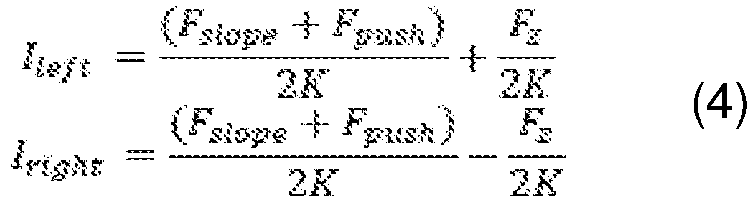
- It is observed that the user can act on how much the motors are enslaved by means of the external device, and consequently on the torque generated by them, for taking into account the type of the roadway. For example, the user can select among several predefined types of the roadway (for example: smooth, normal, rough).
- According to a possible embodiment, the control unit 2 is configured so that the
torque allocating module 10 compensates possible differences between the radiuses of the two wheels ascribed to manufacturing mistakes or to an asymmetric wear of the same. Indeed, the differences between the radiuses of the two wheels can determine an asymmetric slavery of the motors. Therefore, it can occur the following condition:
- In order to avoid this possible inconvenience, the control unit 2 can comprise a
module 11 for estimating the effective radiuses Rleft and Rright based on the signals representing the speeds vleft, vright of the wheels and the yaw speed ωz. The estimate can be obtained when the device moves straight or almost straight and therefore the yaw angular speed ωz is zero or less than a threshold value. Under such condition, it is for example possible to determine the least offsets δleft and δright in order to verify the following condition:
- Based on the effective values of the radiuses Rleft and Rright of the two wheels, the
torque allocating module 10 can correct the command signals Ileft, Iright, calculated by assuming the radiuses of the two wheels are equal, so that the torques generated by the motors offset the asymmetry caused by different radiuses of the wheels. - It is observed that the
module 11 for estimating the effective radiuses Rleft and Rright is, more generally, capable of compensating conditions causing a drift. Apart from the differences between the radiuses of the wheels caused by wear or manufacturing errors, such condition can be verified for example in the following cases: friction differences between the wheels on the two sides of the vehicle (for example if one of the two wheels is partially deflated), differences in the roadway between one side and the other of the device, asymmetric thrust exerted by the user. - A further asymmetry, which can be found, can be determined by the positions of the transported loads. This aspect can be monitored by the suspension elongation sensors, if present, and can be consequently compensated by the torque allocating module.
- According to a possible embodiment, the
torque allocating module 10 further receives, at the input, the signal representing the presence of the user (U), from the associated presence sensor indicated by 12 inFigure 2 . Specifically, thetorque allocating module 10 is configured to generate the motor commanding signals Ileft, Iright only if the user presence sensor detects the presence thereof. In other words, if the presence of the user is not detected, the motors are deactivated, and the device becomes a completely passive system. Consequently, the device is prevented from being inadvertently actuated even though the user is present. - According to an embodiment, the control unit 2 comprises a
module 13 for identifying a maneuver for getting past an obstacle. In this regard, it is considered a case shown inFigure 3 , wherein the user moving the baby carriage comes across a step. Under such condition, the typical maneuver performed by user is to raise the front wheels by applying a downwardly directed force Fuser, then, with the front wheels still raised, he/she longitudinally pushes the carriage for getting past the step. Under such condition, the carriage is tilted and consequently theslope estimating module 3 estimates an erroneous slope α, because is not determined by the slope of the path, but by a maneuver performed by the user. Under such condition, thetorque allocating module 10 is required to neglect the slope compensating force Fslope, in order to prevent the motors from generating a torque not according to the real condition under which the device is subjected, in other words not a sloping road but an obstacle present along the path. - Advantageously, the
module 13 identifying a maneuver for getting past an obstacle, is configured to identify the presence of an obstacle based on the slope α estimated by themodule 3, on signals representing the suspensions elongations θleft, θright, and based on the speeds vleft, vright of the wheels, and to provide, at the output, a signal indicating the presence/absence (P/A) of the obstacle, which is supplied to thetorque allocating module 10. This latter, in turn, is configured to neglect the slope compensating force Fslope if theobstacle identifying module 13 supplies an obstacle presence signal. - The several possible obstacles which can be found by the
device 1, can be got past by standard maneuvers which determine specific trends of the signals entering themodule 13 identifying a maneuver for getting past an obstacle. For example, still referring to the condition ofFigure 3 , upon bringing the speed to zero, it is detected a compression of the suspensions caused by the raising front wheels and simultaneously an abrupt increase of the estimated slope α. Then, it is detected a speed of the wheels when the baby carriage is raised on the step, followed by an abrupt drop of the estimated slope and also by a compression decrease of the suspensions. Therefore, the maneuver for getting past the obstacle can be codified and identified by themodule 13. - According to an embodiment, the
movement device 1 comprises anassistance command 14 commandable by the user for increasing the power of the motors. Theassistance command 14 is connected to thetorque allocating module 10 so that, upon requiring a power increase by the user, this generates command signals Ileft, Iright so that the motors generate an additional torque, which can be used, for example, for more easily getting past an obstacle, e.g. a step. According to a further possible variant, further assistance commands are provided, for example for enabling a user to select a different direction of the additional torque that must be supplied by the motor. For example, if thebaby carriage 1 is pulled instead of being pushed, as shown inFigure 3 , the additional torque supplied by the motors must have a direction opposite to the one of a pushedcarriage 1. - According to a possible further embodiment, the
torque allocating module 10 can be commandable, for example, by the external device, so that the motors obey to predefined torque laws. For example, in case of a baby carriage, the motors can be commanded for imparting to the carriage movements for rocking the baby without requiring a manual action by the user (oscillating movements as: back-and-forth, right-and-left) - The movement device, according to the invention, can be further set for performing additional functions apart the above described ones. For example, the motors can be set so that they exert a resistance to the advancement (settable by the user, for example through his/her own smartphone) for generating an additional effort perceived by the user. Such setting has the result of physically exercising the user and recharging the batteries.
- According to a possible embodiment, the user presence detecting sensor, hereinbefore described, can further have an anti-theft function.
- It is observed that in present description and in the attached claims, the elements called "module", can be implemented by hardware devices (for example central processing units), by software or by a combination of hardware and software.
- To the described embodiments of the motorized movement device according to the invention, a person skilled in the art in order to satisfy specific contingent needs, could introduce many additions, modifications, or substitutions of elements with other operatively equivalent, without falling out of the scope of the attached claims.
Claims (13)
- Motorized movement device (1) comprising:- a frame (101);- a first (102') and second (102") wheels connected to the frame (101), and a first and second motors connected respectively to the first (102') and second (102") wheels and commandable by respective command signals (Ileft, Iright) characterized in that the motorized movement device (1) comprises:- an inertial measuring unit configured to detect the longitudinal acceleration (ax), the pitch angular speed (ωy), and the yaw angular speed (ωz) of the movement device (1) and for providing signals representative of the same;- sensors for detecting the speeds (vleft, vright) of said first (102') and second (102") wheels configured to provide signals representative of the same;- a control unit (2) comprising:• a module (3) for estimating the slope (α) based on the signals representative of the longitudinal acceleration (ax), of the pitch angular speed (ωy), and of the speeds (vleft, vright) of said first (102') and second (102") wheels;• a module (4) for estimating the longitudinal thrust (Fx) exerted by a user to the device (1) based on the signals representative of the longitudinal acceleration (ax), of the speeds (vleft, vright) of said first (102') and second (102") wheels, of the command signals of the motors (Ileft, Iright) and of the estimated slope (α);• a module (6) for estimating the yaw torque (τz) applied by the user on the movement device (1) based on the signal representative of the yaw angular speed (wz);• a module (7) for compensating the slope, configured to determine a slope compensating force (Fslope) based on the estimated slope (α);• a thrust amplifying module (8), configured to determine a thrust aiding force (Fpush) based on the estimated longitudinal thrust (Fx);• a yaw torque amplifying module (9), configured to determine a steering aiding force (Fz) based on the estimated yaw torque (τz);• a torque allocating module (10), configured to determine said command signals (Ileft, Iright) of the first and second motors based on the slope compensating force (Fslope), on the thrust aiding force (Fpush) and on the steering aiding force (Fz).
- Motorized movement device (1) according to claim 1, further comprising a first (104') and a second (104") suspensions operatively interposed between the frame (101) and said first (102') and second (102") wheels, and sensors for detecting the elongations (θleft, θright) of said first (104') and second (104") suspensions, configured to provide signals representative of the same.
- Motorized movement device (1) according to claim 2, wherein said slope (α) estimating module (3) is configured to estimate said slope (α) further based on said signals representative of the elongations (θleft, θright) of said first (104') and second (104") suspensions.
- Motorized movement device (1) according to claim 2 or 3, comprising a module (5) for estimating the mass (M) of the movement device (1) and of the load transported by it based on signals representative of the elongations (θleft, θright) of the suspensions (104', 104"), of the speeds (vleft, vright) of the wheels (102', 102") and of the estimated slope (α).
- Motorized movement device (1) according to claim 4, wherein said module (4) for estimating the longitudinal thrust (Fx) exerted by the user on the device (1) is configured to estimate said longitudinal thrust (Fx) further based on said estimated mass (M).
- Motorized movement device (1) according to claim 4 or 5, wherein said module (6) for estimating the yaw torque (τz) applied by the user on the movement device (1) is configured to estimate the yaw torque (τz) further based on said estimated mass (M).
- Motorized movement device (1) according to any of claims from 4 to 6, wherein said slope compensating module (7) is configured to determine the slope compensating force (Fslope) further based on said estimated mass (M).
- Motorized movement device (1) according to any of the preceding claims, wherein the control unit (2) further comprises a module (11) for estimating the effective radii (Rleft, Rright) of said first (102') and second wheels (102") based on signals representative of the speeds (vleft, vright) of the wheels (102', 102") and of the yaw angular speed (ωz), said torque allocating module (10) being connected to the module (11) for estimating the effective radii and being configured to correct the motors command signals (Ileft, Iright), based on said estimated effective radii (Rleft, Rright).
- Motorized movement device (1) according to any of the preceding claims, further comprising one or more handles (103) and one or more sensors (12) associated to said one or more handles and configured to detect the presence of the user (U) and to provide a signal representative of such presence, wherein the torque allocating module (10) is connected to said sensors detecting the presence of the user and is configured to generate said motors commanding signals (Ileft, Iright) only if the one or more sensors detecting the presence of the user supply an user presence signal.
- Motorized movement device (1) according to any of claims from 2 to 9, wherein the control unit (2) comprises a module (13) for identifying a maneuver for getting past an obstacle, configured to identify the presence of an obstacle (P/A) based on the trend of the estimated slope (α), of the signals representative of the elongations of the suspensions (θleft, θright) and of the wheels speeds (vleft, vright), and to provide, at the output, a signal indicating the presence or absence of said obstacle, wherein the torque allocating module (10) is connected to the module (13) identifying a maneuver for getting past an obstacle, and is configured to disregard the slope compensating force (Fslope) in case the module for acknowledging the maneuver for getting past an obstacle (13), supplies an obstacle presence signal.
- Motorized movement device (1) according to any of the preceding claims, further comprising at least one assistance command (14), commandable by the user and connected to the torque allocating module (10) so that, upon activating the assistance command (14) by the user, the torque allocating module (10) outputs command signals (Ileft, Iright) so that the motors supply an additional driving torque.
- Motorized movement device (1) according to any of the preceding claims, further comprising a module communicating with an external device, such as mobile phone, or a smartphone, connected to the control unit (2), so that operative parameters of the control unit (2) are monitorable and/or settable by said external device.
- Motorized movement device (1) according to any of the preceding claims, selected in the group consisting of: baby carriages, trolleys, carts for transporting goods, shopping carts, golf club trolleys, airport trolleys, suitcases, disabled chairs, wheelchairs, stretchers, walkers, hospital beds.
Applications Claiming Priority (2)
| Application Number | Priority Date | Filing Date | Title |
|---|---|---|---|
| IT102017000041556A IT201700041556A1 (en) | 2017-04-13 | 2017-04-13 | Motorized handling device pushed by hand |
| PCT/IB2018/052279 WO2018189621A1 (en) | 2017-04-13 | 2018-04-03 | Hand-pushed motorized movement device |
Publications (2)
| Publication Number | Publication Date |
|---|---|
| EP3609768A1 EP3609768A1 (en) | 2020-02-19 |
| EP3609768B1 true EP3609768B1 (en) | 2021-02-17 |
Family
ID=59811757
Family Applications (1)
| Application Number | Title | Priority Date | Filing Date |
|---|---|---|---|
| EP18717705.0A Active EP3609768B1 (en) | 2017-04-13 | 2018-04-03 | Hand-pushed motorized movement device |
Country Status (5)
| Country | Link |
|---|---|
| US (1) | US11498432B2 (en) |
| EP (1) | EP3609768B1 (en) |
| JP (1) | JP6984000B2 (en) |
| IT (1) | IT201700041556A1 (en) |
| WO (1) | WO2018189621A1 (en) |
Cited By (1)
| Publication number | Priority date | Publication date | Assignee | Title |
|---|---|---|---|---|
| US20210378891A1 (en) * | 2020-06-05 | 2021-12-09 | Toyota Motor North America, Inc. | Wheelchair systems and methods enabling fine manual motion control |
Families Citing this family (8)
| Publication number | Priority date | Publication date | Assignee | Title |
|---|---|---|---|---|
| WO2019003260A1 (en) * | 2017-06-26 | 2019-01-03 | ヤマハ発動機株式会社 | Power assist wheelchair, power assist unit for wheelchair, control device for power assist wheelchair, control method for power assist wheelchair, and program |
| CN110481343B (en) * | 2019-08-30 | 2020-10-02 | 东风汽车集团有限公司 | Combined second-order sliding mode control method for torque compensation of four-wheel in-wheel motor-driven vehicles |
| DE102021206057A1 (en) | 2021-06-15 | 2022-12-15 | Robert Bosch Gesellschaft mit beschränkter Haftung | Transport device with a support device |
| CN113246747A (en) * | 2021-06-30 | 2021-08-13 | 奇瑞商用车(安徽)有限公司 | Control method for hill start |
| EP4344525B1 (en) * | 2022-09-27 | 2024-10-02 | Nanjing Chervon Industry Co., Ltd. | Walk-behind hand-guided working machine |
| KR102726501B1 (en) * | 2022-12-19 | 2024-11-06 | 인천대학교 산학협력단 | Method and apparatus for controlling state space of electric wheelchair considering variable parameters |
| DE102024001250B3 (en) * | 2024-04-18 | 2025-08-07 | Lukas Manuel Bergmann | Model-based force estimation device for a motorized vehicle |
| CN119190161B (en) * | 2024-08-30 | 2026-04-28 | 宁波稳泰运动器材有限公司 | A dual-motor trolley automatic correction system |
Family Cites Families (34)
| Publication number | Priority date | Publication date | Assignee | Title |
|---|---|---|---|---|
| US7090040B2 (en) * | 1993-02-24 | 2006-08-15 | Deka Products Limited Partnership | Motion control of a transporter |
| DE9311075U1 (en) * | 1993-07-24 | 1994-11-24 | Strothmann, Rolf, Dr., 66123 Saarbrücken | Electric drive of a hand-drawn or pushed, mobile object |
| JP3032698B2 (en) * | 1995-04-14 | 2000-04-17 | 松下電工株式会社 | Transport vehicle with power assist |
| US6003627A (en) * | 1996-08-08 | 1999-12-21 | Nabco Limited | Motor-driven vehicle control apparatus |
| DE19744083A1 (en) * | 1997-10-06 | 1999-04-08 | Bosch Gmbh Robert | Arrangement for producing trigger signal for safety unit in vehicle with roll operation |
| JP2003517808A (en) * | 1999-08-31 | 2003-05-27 | デルタグライド、インコーポレイテッド | Power assist vehicle |
| JP3548477B2 (en) * | 2000-01-25 | 2004-07-28 | 鈴木 康之 | Travel speed control device for electric light vehicle and electric light vehicle |
| DE10053043A1 (en) * | 2000-10-13 | 2001-09-27 | Frieder Herb | Electrically powered scooter has drive whose operation is managed via sensing arrangement that switches it on and off in relation to motive power depending on acceleration/speed |
| US6462493B2 (en) * | 2001-02-14 | 2002-10-08 | Mey-Chu Lan | Driving control apparatus of motorized scooter |
| JP2004120875A (en) * | 2002-09-25 | 2004-04-15 | Matsushita Electric Works Ltd | Power vehicle |
| JP3922554B2 (en) * | 2002-09-25 | 2007-05-30 | 松下電工株式会社 | Power assisted transport vehicle |
| JP2004359008A (en) * | 2003-06-02 | 2004-12-24 | Sony Corp | Carrying vehicle and controlling method thereof |
| JP4495444B2 (en) * | 2003-11-25 | 2010-07-07 | 久 高橋 | Power assist type moving body |
| WO2005094480A2 (en) * | 2004-03-23 | 2005-10-13 | Motiv Technology, Inc | Power assist device |
| US7826948B2 (en) * | 2004-10-15 | 2010-11-02 | Ford Global Technologies | Vehicle loading based vehicle dynamic and safety related characteristic adjusting system |
| JP2009153575A (en) * | 2007-12-25 | 2009-07-16 | Panasonic Electric Works Co Ltd | Food service cart |
| JP5186041B2 (en) * | 2009-06-02 | 2013-04-17 | パナソニック株式会社 | Electric vehicle and control method |
| DE102009044840A1 (en) * | 2009-12-09 | 2011-06-16 | Clean Mobile Ag | Multiple stroller with seating areas for at least two children |
| JP5667826B2 (en) * | 2010-09-27 | 2015-02-12 | 株式会社ミツバ | Electric handy cart |
| WO2012163789A1 (en) * | 2011-05-27 | 2012-12-06 | Micro-Beam Sa | Electrically assisted street scooter |
| DE102011114337A1 (en) * | 2011-09-23 | 2013-03-28 | Bernd von Löbbecke | Motor control for an electric auxiliary drive |
| FR2990398B1 (en) * | 2012-05-11 | 2016-01-22 | Coutier Ind | MANUAL WORKSHOP TROLLEY WITH ASSISTED STARTING |
| DE102013100088A1 (en) * | 2013-01-07 | 2014-07-10 | Rolf Strothmann | For movement by muscle power provided device, in particular vehicle |
| ITMI20130802A1 (en) * | 2013-05-16 | 2014-11-17 | Novia S R L E | SYSTEM FOR THE ESTIMATE OF ONE OR MORE PARAMETERS RELATED TO THE LOADING OF A VEHICLE, IN PARTICULAR OF ITS ABSOLUTE VALUE AND ITS DISTRIBUTION |
| JP2016525977A (en) * | 2013-05-21 | 2016-09-01 | アルジョ ホスピタル イクイップメント アクチエボラグArjo Hospital Equipment AB | Auxiliary propulsion system, method and chassis |
| JP2015047298A (en) * | 2013-08-30 | 2015-03-16 | 船井電機株式会社 | Walking assist moving body |
| JP6187049B2 (en) * | 2013-08-30 | 2017-08-30 | 船井電機株式会社 | Walking assist moving body |
| JP6123906B2 (en) * | 2013-10-10 | 2017-05-10 | 株式会社村田製作所 | Wheelbarrow |
| DE112014004677T5 (en) * | 2013-10-11 | 2016-07-21 | Murata Manufacturing Co., Ltd. | Schiebewagen |
| JP5638712B1 (en) * | 2014-01-17 | 2014-12-10 | シャープ株式会社 | stroller |
| FR3018057B1 (en) * | 2014-02-28 | 2018-06-29 | Commissariat A L'energie Atomique Et Aux Energies Alternatives | ASSISTING THE MOVEMENT OF A ROLLING OBJECT BY ASSERVING USING THE ACCELERATION OF THE ROLLING OBJECT |
| EP3126184B1 (en) * | 2014-04-04 | 2019-09-04 | Superpedestrian, Inc. | Systems, methods, and devices for the operation of electrically motorized vehicles |
| US10384742B2 (en) * | 2014-11-18 | 2019-08-20 | Zehus S.P.A. | System for controlling the motion of an impulsive-type human powered vehicle |
| JP6794099B2 (en) * | 2015-06-26 | 2020-12-02 | シャープ株式会社 | Power-assisted vehicles, control methods, and programs |
-
2017
- 2017-04-13 IT IT102017000041556A patent/IT201700041556A1/en unknown
-
2018
- 2018-04-03 US US16/604,333 patent/US11498432B2/en active Active
- 2018-04-03 WO PCT/IB2018/052279 patent/WO2018189621A1/en not_active Ceased
- 2018-04-03 EP EP18717705.0A patent/EP3609768B1/en active Active
- 2018-04-03 JP JP2020505544A patent/JP6984000B2/en active Active
Non-Patent Citations (1)
| Title |
|---|
| None * |
Cited By (2)
| Publication number | Priority date | Publication date | Assignee | Title |
|---|---|---|---|---|
| US20210378891A1 (en) * | 2020-06-05 | 2021-12-09 | Toyota Motor North America, Inc. | Wheelchair systems and methods enabling fine manual motion control |
| US11660240B2 (en) * | 2020-06-05 | 2023-05-30 | Toyota Motor North America, Inc. | Wheelchair systems and methods enabling fine manual motion control |
Also Published As
| Publication number | Publication date |
|---|---|
| WO2018189621A1 (en) | 2018-10-18 |
| US11498432B2 (en) | 2022-11-15 |
| US20200156482A1 (en) | 2020-05-21 |
| EP3609768A1 (en) | 2020-02-19 |
| JP6984000B2 (en) | 2021-12-17 |
| JP2020516543A (en) | 2020-06-11 |
| IT201700041556A1 (en) | 2018-10-13 |
Similar Documents
| Publication | Publication Date | Title |
|---|---|---|
| EP3609768B1 (en) | Hand-pushed motorized movement device | |
| JP7010883B2 (en) | Auxiliary propulsion system, method and chassis | |
| KR102186840B1 (en) | Electromotive apparatus for assisting user in walking | |
| CA2990889C (en) | Brake assistance system for patient handling equipment | |
| US20180296426A1 (en) | Apparatuses, systems and methods for controlling exoskeletons | |
| EP2883525A1 (en) | Walking assistance moving vehicle | |
| US20110015842A1 (en) | Power assisted vehicle | |
| JP2016525977A5 (en) | ||
| US20100235028A1 (en) | Traveling apparatus and method of controlling same | |
| JP6799789B2 (en) | Walking support robot and walking support method | |
| KR102457604B1 (en) | Intelligent Walking Assist Device | |
| US20220062075A1 (en) | Low-profile and high-load ball-balancing rolling system | |
| US9845101B2 (en) | Pushcart | |
| JPH11171038A (en) | Conveying device | |
| EP3727924B1 (en) | Motorized handling device pushed by hand provided with a safety module | |
| JP4411415B2 (en) | Passive type mobile trolley | |
| US11294415B2 (en) | Device and system for controlling a transport vehicle | |
| EP4082509A1 (en) | Electric braking mechanism-equipped vehicle, wheel unit, and control program for wheel unit | |
| KR101548930B1 (en) | Apparatus for improve the linearity of the walking assistant robot to move on lateral slopes | |
| AU2021217999A1 (en) | Device and system for controlling a transport vehicle | |
| KR102507726B1 (en) | Transfer Robot system | |
| KR20250113637A (en) | Smart walking assist apparatus for including function of auto horizontal level adjustment | |
| KR20250164843A (en) | Patient transport assistance and control | |
| JP5704283B2 (en) | Wheelbarrow | |
| CN119360335A (en) | Stereoscopic vision intelligent perception and control method and device for ward environment of medical transfer machine |
Legal Events
| Date | Code | Title | Description |
|---|---|---|---|
| STAA | Information on the status of an ep patent application or granted ep patent |
Free format text: STATUS: UNKNOWN |
|
| STAA | Information on the status of an ep patent application or granted ep patent |
Free format text: STATUS: THE INTERNATIONAL PUBLICATION HAS BEEN MADE |
|
| PUAI | Public reference made under article 153(3) epc to a published international application that has entered the european phase |
Free format text: ORIGINAL CODE: 0009012 |
|
| STAA | Information on the status of an ep patent application or granted ep patent |
Free format text: STATUS: REQUEST FOR EXAMINATION WAS MADE |
|
| 17P | Request for examination filed |
Effective date: 20191003 |
|
| AK | Designated contracting states |
Kind code of ref document: A1 Designated state(s): AL AT BE BG CH CY CZ DE DK EE ES FI FR GB GR HR HU IE IS IT LI LT LU LV MC MK MT NL NO PL PT RO RS SE SI SK SM TR |
|
| AX | Request for extension of the european patent |
Extension state: BA ME |
|
| DAV | Request for validation of the european patent (deleted) | ||
| DAX | Request for extension of the european patent (deleted) | ||
| GRAP | Despatch of communication of intention to grant a patent |
Free format text: ORIGINAL CODE: EPIDOSNIGR1 |
|
| STAA | Information on the status of an ep patent application or granted ep patent |
Free format text: STATUS: GRANT OF PATENT IS INTENDED |
|
| INTG | Intention to grant announced |
Effective date: 20201127 |
|
| GRAS | Grant fee paid |
Free format text: ORIGINAL CODE: EPIDOSNIGR3 |
|
| GRAA | (expected) grant |
Free format text: ORIGINAL CODE: 0009210 |
|
| STAA | Information on the status of an ep patent application or granted ep patent |
Free format text: STATUS: THE PATENT HAS BEEN GRANTED |
|
| AK | Designated contracting states |
Kind code of ref document: B1 Designated state(s): AL AT BE BG CH CY CZ DE DK EE ES FI FR GB GR HR HU IE IS IT LI LT LU LV MC MK MT NL NO PL PT RO RS SE SI SK SM TR |
|
| REG | Reference to a national code |
Ref country code: GB Ref legal event code: FG4D |
|
| REG | Reference to a national code |
Ref country code: CH Ref legal event code: EP |
|
| REG | Reference to a national code |
Ref country code: DE Ref legal event code: R096 Ref document number: 602018012684 Country of ref document: DE |
|
| REG | Reference to a national code |
Ref country code: AT Ref legal event code: REF Ref document number: 1361116 Country of ref document: AT Kind code of ref document: T Effective date: 20210315 |
|
| REG | Reference to a national code |
Ref country code: IE Ref legal event code: FG4D |
|
| REG | Reference to a national code |
Ref country code: LT Ref legal event code: MG9D |
|
| REG | Reference to a national code |
Ref country code: NL Ref legal event code: MP Effective date: 20210217 |
|
| PG25 | Lapsed in a contracting state [announced via postgrant information from national office to epo] |
Ref country code: BG Free format text: LAPSE BECAUSE OF FAILURE TO SUBMIT A TRANSLATION OF THE DESCRIPTION OR TO PAY THE FEE WITHIN THE PRESCRIBED TIME-LIMIT Effective date: 20210517 Ref country code: HR Free format text: LAPSE BECAUSE OF FAILURE TO SUBMIT A TRANSLATION OF THE DESCRIPTION OR TO PAY THE FEE WITHIN THE PRESCRIBED TIME-LIMIT Effective date: 20210217 Ref country code: GR Free format text: LAPSE BECAUSE OF FAILURE TO SUBMIT A TRANSLATION OF THE DESCRIPTION OR TO PAY THE FEE WITHIN THE PRESCRIBED TIME-LIMIT Effective date: 20210518 Ref country code: FI Free format text: LAPSE BECAUSE OF FAILURE TO SUBMIT A TRANSLATION OF THE DESCRIPTION OR TO PAY THE FEE WITHIN THE PRESCRIBED TIME-LIMIT Effective date: 20210217 Ref country code: NO Free format text: LAPSE BECAUSE OF FAILURE TO SUBMIT A TRANSLATION OF THE DESCRIPTION OR TO PAY THE FEE WITHIN THE PRESCRIBED TIME-LIMIT Effective date: 20210517 Ref country code: PT Free format text: LAPSE BECAUSE OF FAILURE TO SUBMIT A TRANSLATION OF THE DESCRIPTION OR TO PAY THE FEE WITHIN THE PRESCRIBED TIME-LIMIT Effective date: 20210617 Ref country code: LT Free format text: LAPSE BECAUSE OF FAILURE TO SUBMIT A TRANSLATION OF THE DESCRIPTION OR TO PAY THE FEE WITHIN THE PRESCRIBED TIME-LIMIT Effective date: 20210217 |
|
| REG | Reference to a national code |
Ref country code: AT Ref legal event code: MK05 Ref document number: 1361116 Country of ref document: AT Kind code of ref document: T Effective date: 20210217 |
|
| PG25 | Lapsed in a contracting state [announced via postgrant information from national office to epo] |
Ref country code: LV Free format text: LAPSE BECAUSE OF FAILURE TO SUBMIT A TRANSLATION OF THE DESCRIPTION OR TO PAY THE FEE WITHIN THE PRESCRIBED TIME-LIMIT Effective date: 20210217 Ref country code: PL Free format text: LAPSE BECAUSE OF FAILURE TO SUBMIT A TRANSLATION OF THE DESCRIPTION OR TO PAY THE FEE WITHIN THE PRESCRIBED TIME-LIMIT Effective date: 20210217 Ref country code: NL Free format text: LAPSE BECAUSE OF FAILURE TO SUBMIT A TRANSLATION OF THE DESCRIPTION OR TO PAY THE FEE WITHIN THE PRESCRIBED TIME-LIMIT Effective date: 20210217 Ref country code: RS Free format text: LAPSE BECAUSE OF FAILURE TO SUBMIT A TRANSLATION OF THE DESCRIPTION OR TO PAY THE FEE WITHIN THE PRESCRIBED TIME-LIMIT Effective date: 20210217 Ref country code: SE Free format text: LAPSE BECAUSE OF FAILURE TO SUBMIT A TRANSLATION OF THE DESCRIPTION OR TO PAY THE FEE WITHIN THE PRESCRIBED TIME-LIMIT Effective date: 20210217 |
|
| PG25 | Lapsed in a contracting state [announced via postgrant information from national office to epo] |
Ref country code: IS Free format text: LAPSE BECAUSE OF FAILURE TO SUBMIT A TRANSLATION OF THE DESCRIPTION OR TO PAY THE FEE WITHIN THE PRESCRIBED TIME-LIMIT Effective date: 20210617 |
|
| PG25 | Lapsed in a contracting state [announced via postgrant information from national office to epo] |
Ref country code: AT Free format text: LAPSE BECAUSE OF FAILURE TO SUBMIT A TRANSLATION OF THE DESCRIPTION OR TO PAY THE FEE WITHIN THE PRESCRIBED TIME-LIMIT Effective date: 20210217 Ref country code: SM Free format text: LAPSE BECAUSE OF FAILURE TO SUBMIT A TRANSLATION OF THE DESCRIPTION OR TO PAY THE FEE WITHIN THE PRESCRIBED TIME-LIMIT Effective date: 20210217 Ref country code: CZ Free format text: LAPSE BECAUSE OF FAILURE TO SUBMIT A TRANSLATION OF THE DESCRIPTION OR TO PAY THE FEE WITHIN THE PRESCRIBED TIME-LIMIT Effective date: 20210217 Ref country code: EE Free format text: LAPSE BECAUSE OF FAILURE TO SUBMIT A TRANSLATION OF THE DESCRIPTION OR TO PAY THE FEE WITHIN THE PRESCRIBED TIME-LIMIT Effective date: 20210217 |
|
| REG | Reference to a national code |
Ref country code: DE Ref legal event code: R097 Ref document number: 602018012684 Country of ref document: DE |
|
| PG25 | Lapsed in a contracting state [announced via postgrant information from national office to epo] |
Ref country code: MC Free format text: LAPSE BECAUSE OF FAILURE TO SUBMIT A TRANSLATION OF THE DESCRIPTION OR TO PAY THE FEE WITHIN THE PRESCRIBED TIME-LIMIT Effective date: 20210217 Ref country code: SK Free format text: LAPSE BECAUSE OF FAILURE TO SUBMIT A TRANSLATION OF THE DESCRIPTION OR TO PAY THE FEE WITHIN THE PRESCRIBED TIME-LIMIT Effective date: 20210217 Ref country code: RO Free format text: LAPSE BECAUSE OF FAILURE TO SUBMIT A TRANSLATION OF THE DESCRIPTION OR TO PAY THE FEE WITHIN THE PRESCRIBED TIME-LIMIT Effective date: 20210217 Ref country code: DK Free format text: LAPSE BECAUSE OF FAILURE TO SUBMIT A TRANSLATION OF THE DESCRIPTION OR TO PAY THE FEE WITHIN THE PRESCRIBED TIME-LIMIT Effective date: 20210217 |
|
| PLBE | No opposition filed within time limit |
Free format text: ORIGINAL CODE: 0009261 |
|
| STAA | Information on the status of an ep patent application or granted ep patent |
Free format text: STATUS: NO OPPOSITION FILED WITHIN TIME LIMIT |
|
| PG25 | Lapsed in a contracting state [announced via postgrant information from national office to epo] |
Ref country code: LU Free format text: LAPSE BECAUSE OF NON-PAYMENT OF DUE FEES Effective date: 20210403 |
|
| REG | Reference to a national code |
Ref country code: BE Ref legal event code: MM Effective date: 20210430 |
|
| 26N | No opposition filed |
Effective date: 20211118 |
|
| PG25 | Lapsed in a contracting state [announced via postgrant information from national office to epo] |
Ref country code: ES Free format text: LAPSE BECAUSE OF FAILURE TO SUBMIT A TRANSLATION OF THE DESCRIPTION OR TO PAY THE FEE WITHIN THE PRESCRIBED TIME-LIMIT Effective date: 20210217 Ref country code: CH Free format text: LAPSE BECAUSE OF NON-PAYMENT OF DUE FEES Effective date: 20210430 Ref country code: AL Free format text: LAPSE BECAUSE OF FAILURE TO SUBMIT A TRANSLATION OF THE DESCRIPTION OR TO PAY THE FEE WITHIN THE PRESCRIBED TIME-LIMIT Effective date: 20210217 Ref country code: LI Free format text: LAPSE BECAUSE OF NON-PAYMENT OF DUE FEES Effective date: 20210430 |
|
| PG25 | Lapsed in a contracting state [announced via postgrant information from national office to epo] |
Ref country code: SI Free format text: LAPSE BECAUSE OF FAILURE TO SUBMIT A TRANSLATION OF THE DESCRIPTION OR TO PAY THE FEE WITHIN THE PRESCRIBED TIME-LIMIT Effective date: 20210217 |
|
| PG25 | Lapsed in a contracting state [announced via postgrant information from national office to epo] |
Ref country code: IT Free format text: LAPSE BECAUSE OF FAILURE TO SUBMIT A TRANSLATION OF THE DESCRIPTION OR TO PAY THE FEE WITHIN THE PRESCRIBED TIME-LIMIT Effective date: 20210217 Ref country code: IE Free format text: LAPSE BECAUSE OF NON-PAYMENT OF DUE FEES Effective date: 20210403 |
|
| PG25 | Lapsed in a contracting state [announced via postgrant information from national office to epo] |
Ref country code: IS Free format text: LAPSE BECAUSE OF FAILURE TO SUBMIT A TRANSLATION OF THE DESCRIPTION OR TO PAY THE FEE WITHIN THE PRESCRIBED TIME-LIMIT Effective date: 20210617 |
|
| PG25 | Lapsed in a contracting state [announced via postgrant information from national office to epo] |
Ref country code: BE Free format text: LAPSE BECAUSE OF NON-PAYMENT OF DUE FEES Effective date: 20210430 |
|
| PG25 | Lapsed in a contracting state [announced via postgrant information from national office to epo] |
Ref country code: CY Free format text: LAPSE BECAUSE OF FAILURE TO SUBMIT A TRANSLATION OF THE DESCRIPTION OR TO PAY THE FEE WITHIN THE PRESCRIBED TIME-LIMIT Effective date: 20210217 |
|
| PG25 | Lapsed in a contracting state [announced via postgrant information from national office to epo] |
Ref country code: HU Free format text: LAPSE BECAUSE OF FAILURE TO SUBMIT A TRANSLATION OF THE DESCRIPTION OR TO PAY THE FEE WITHIN THE PRESCRIBED TIME-LIMIT; INVALID AB INITIO Effective date: 20180403 |
|
| PG25 | Lapsed in a contracting state [announced via postgrant information from national office to epo] |
Ref country code: MK Free format text: LAPSE BECAUSE OF FAILURE TO SUBMIT A TRANSLATION OF THE DESCRIPTION OR TO PAY THE FEE WITHIN THE PRESCRIBED TIME-LIMIT Effective date: 20210217 |
|
| PG25 | Lapsed in a contracting state [announced via postgrant information from national office to epo] |
Ref country code: TR Free format text: LAPSE BECAUSE OF FAILURE TO SUBMIT A TRANSLATION OF THE DESCRIPTION OR TO PAY THE FEE WITHIN THE PRESCRIBED TIME-LIMIT Effective date: 20210217 |
|
| PG25 | Lapsed in a contracting state [announced via postgrant information from national office to epo] |
Ref country code: MT Free format text: LAPSE BECAUSE OF FAILURE TO SUBMIT A TRANSLATION OF THE DESCRIPTION OR TO PAY THE FEE WITHIN THE PRESCRIBED TIME-LIMIT Effective date: 20210217 |
|
| PGFP | Annual fee paid to national office [announced via postgrant information from national office to epo] |
Ref country code: DE Payment date: 20250422 Year of fee payment: 8 |
|
| PGFP | Annual fee paid to national office [announced via postgrant information from national office to epo] |
Ref country code: GB Payment date: 20250423 Year of fee payment: 8 |
|
| PGFP | Annual fee paid to national office [announced via postgrant information from national office to epo] |
Ref country code: FR Payment date: 20250425 Year of fee payment: 8 |