EP3609110A1 - Method and device for estimating timing location - Google Patents
Method and device for estimating timing location Download PDFInfo
- Publication number
- EP3609110A1 EP3609110A1 EP18778217.2A EP18778217A EP3609110A1 EP 3609110 A1 EP3609110 A1 EP 3609110A1 EP 18778217 A EP18778217 A EP 18778217A EP 3609110 A1 EP3609110 A1 EP 3609110A1
- Authority
- EP
- European Patent Office
- Prior art keywords
- preamble
- correlation value
- power
- preamble subsequence
- subsequence
- Prior art date
- Legal status (The legal status is an assumption and is not a legal conclusion. Google has not performed a legal analysis and makes no representation as to the accuracy of the status listed.)
- Granted
Links
Images



Classifications
-
- H—ELECTRICITY
- H04—ELECTRIC COMMUNICATION TECHNIQUE
- H04L—TRANSMISSION OF DIGITAL INFORMATION, e.g. TELEGRAPHIC COMMUNICATION
- H04L27/00—Modulated-carrier systems
- H04L27/26—Systems using multi-frequency codes
-
- H—ELECTRICITY
- H04—ELECTRIC COMMUNICATION TECHNIQUE
- H04L—TRANSMISSION OF DIGITAL INFORMATION, e.g. TELEGRAPHIC COMMUNICATION
- H04L5/00—Arrangements affording multiple use of the transmission path
- H04L5/003—Arrangements for allocating sub-channels of the transmission path
- H04L5/0048—Allocation of pilot signals, i.e. of signals known to the receiver
-
- H—ELECTRICITY
- H04—ELECTRIC COMMUNICATION TECHNIQUE
- H04J—MULTIPLEX COMMUNICATION
- H04J13/00—Code division multiplex systems
-
- H—ELECTRICITY
- H04—ELECTRIC COMMUNICATION TECHNIQUE
- H04J—MULTIPLEX COMMUNICATION
- H04J13/00—Code division multiplex systems
- H04J13/0007—Code type
- H04J13/0055—ZCZ [zero correlation zone]
- H04J13/0059—CAZAC [constant-amplitude and zero auto-correlation]
- H04J13/0062—Zadoff-Chu
-
- H—ELECTRICITY
- H04—ELECTRIC COMMUNICATION TECHNIQUE
- H04L—TRANSMISSION OF DIGITAL INFORMATION, e.g. TELEGRAPHIC COMMUNICATION
- H04L27/00—Modulated-carrier systems
-
- H—ELECTRICITY
- H04—ELECTRIC COMMUNICATION TECHNIQUE
- H04L—TRANSMISSION OF DIGITAL INFORMATION, e.g. TELEGRAPHIC COMMUNICATION
- H04L27/00—Modulated-carrier systems
- H04L27/0014—Carrier regulation
-
- H—ELECTRICITY
- H04—ELECTRIC COMMUNICATION TECHNIQUE
- H04L—TRANSMISSION OF DIGITAL INFORMATION, e.g. TELEGRAPHIC COMMUNICATION
- H04L27/00—Modulated-carrier systems
- H04L27/26—Systems using multi-frequency codes
- H04L27/2601—Multicarrier modulation systems
- H04L27/2602—Signal structure
- H04L27/261—Details of reference signals
- H04L27/2613—Structure of the reference signals
-
- H—ELECTRICITY
- H04—ELECTRIC COMMUNICATION TECHNIQUE
- H04L—TRANSMISSION OF DIGITAL INFORMATION, e.g. TELEGRAPHIC COMMUNICATION
- H04L27/00—Modulated-carrier systems
- H04L27/26—Systems using multi-frequency codes
- H04L27/2601—Multicarrier modulation systems
- H04L27/2614—Peak power aspects
-
- H—ELECTRICITY
- H04—ELECTRIC COMMUNICATION TECHNIQUE
- H04L—TRANSMISSION OF DIGITAL INFORMATION, e.g. TELEGRAPHIC COMMUNICATION
- H04L27/00—Modulated-carrier systems
- H04L27/26—Systems using multi-frequency codes
- H04L27/2601—Multicarrier modulation systems
- H04L27/2647—Arrangements specific to the receiver only
- H04L27/2655—Synchronisation arrangements
- H04L27/2662—Symbol synchronisation
- H04L27/2663—Coarse synchronisation, e.g. by correlation
-
- H—ELECTRICITY
- H04—ELECTRIC COMMUNICATION TECHNIQUE
- H04L—TRANSMISSION OF DIGITAL INFORMATION, e.g. TELEGRAPHIC COMMUNICATION
- H04L5/00—Arrangements affording multiple use of the transmission path
-
- H—ELECTRICITY
- H04—ELECTRIC COMMUNICATION TECHNIQUE
- H04W—WIRELESS COMMUNICATION NETWORKS
- H04W74/00—Wireless channel access
- H04W74/08—Non-scheduled access, e.g. ALOHA
-
- H—ELECTRICITY
- H04—ELECTRIC COMMUNICATION TECHNIQUE
- H04W—WIRELESS COMMUNICATION NETWORKS
- H04W74/00—Wireless channel access
- H04W74/08—Non-scheduled access, e.g. ALOHA
- H04W74/0833—Random access procedures, e.g. with 4-step access
Definitions
- the present application relates to the field of wireless communication technologies and particularly to a method and a device of estimating a timing location.
- one M-stage preamble sequence consists of M preamble subsequences and used for one random-access Msg1 transmission.
- the UE User Equipment
- the network (gNB (next generation NodeB)/TRP (Transmission and Reception Point)) will detect the M preamble subsequences contained in the M-stage preamble sequence respectively over the time-frequency resources.
- the M-stage preamble sequence is detected correctly only if the M preamble subsequences are all detected correctly.
- CP Cyclic Prefix
- GT Guard Time
- Each preamble subsequence is selected by the UE to obtain one 2-stage preamble sequence, and transmitted as the Msg1, which is detected respectively at the network side.
- the 2-stage preamble sequence is detected correctly only if the 2 preamble subsequences are both detected correctly.
- the PRACH root sequence uses the ZC (Zadoff-Chu) sequence as the root sequence (ZC root sequence for short below). Since the precursor sequences of each cell are generated by the ZC root sequence through the Ncs (cyclic shift, i.e., zero correlation zone configuration), the number of the preamble sequences of each cell is 64 and the preamble sequence used by the UE is selected randomly or allocated by the gNB (next generation NodeB), there is a need to plan the ZC root sequence index correctly in order to reduce the too large interference of the preamble sequences between the adjacent cells. The purpose of the planning is to allocate a ZC root sequence index to the cells so as to ensure that the preamble sequences generated by the adjacent cells using this index are different, to thereby reduce the mutual interference produced by the adjacent cells using the same preamble sequence.
- ZC root sequence index for short below. Since the precursor sequences of each cell are generated by the ZC root sequence through the Ncs (cyclic shift, i.e., zero correlation zone configuration),
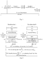
- Fig. 2 is a schematic diagram of the LTE preamble detection algorithm in the prior art, and as shown in Fig. 2 , the main steps of the LTE preamble detection algorithm in the prior art are as follows:
- the present application provides a method and a device of estimating a timing location, so as to solve the problem that the current M-stage preamble sequence scheme has a larger effect on the estimation accuracy of the timing position in the case of the larger frequency offset.
- an embodiment of the present application provides a method of estimating a timing location, which includes:
- the obtaining a detection window where a peak value of a correlation value power of each preamble subsequence is located further includes: obtaining a detection window where a peak value of a correlation value power of each preamble subsequence is located after estimating a Round Trip Time, RTT, timing location.
- the accumulating the correlation value powers of all corresponding positions in the detection window obtained of each preamble subsequence to obtain the cumulative sum of the correlation value powers corresponding to each position includes:
- an embodiment of the present application provides a device of estimating a timing location, which includes:
- the detection window determining module is further configured to: obtain a detection window where a peak value of a correlation value power of each preamble subsequence is located after estimating a Round Trip Time, RTT, timing location.
- the present application has the following beneficial effects.
- the peak power and the noise power for determining the timing position are derived from the cumulative sum of the self-correlation value powers while the cumulative sum of the correlation value powers is the cumulative sum of the correlation value powers of all the preamble subsequences, where for each preamble subsequence, this value is derived from the correlation value power of each preamble subsequence within the detection window where the peak value of the respective correlation value power is located, so the peak power and the noise power for determining the timing position has corrected the error caused by the frequency offset. Therefore, with this solution, the problem that the current M-stage preamble sequence scheme has a larger effect on the estimation accuracy of the timing position in the case of the larger frequency offset can be solved.
- the present application provides a method and a device of estimating a timing location, so as to solve the problem that the self-correlative peak value may provide the imprecise PRACH timing position estimation when there is the large frequency offset between the received preamble and the local preamble.
- an embodiment of the present application provides a method of estimating a timing location, which includes:
- the root index value u is configured at the network side.
- the mod(N_ZC) operation is omitted according to the ZC sequence characteristics.
- the method further includes: solving dT(m) jointly according to the relationship of K TA(m) values and the root index value u when the preamble sequence contains M preamble subsequences, wherein 2 ⁇ K ⁇ M.
- an embodiment of the present application provides a device of estimating a timing location, which includes:
- the index value and frequency offset module is further configured to use the root index value u configured at the network side.
- the timing position estimation error module is further configured to solve dT(m) jointly according to the relationship of K TA(m) values and the root index value u when the preamble sequence contains M preamble subsequences, wherein 2 ⁇ K ⁇ M.
- an embodiment of the present application provides a device of estimating a timing location, which includes:
- the processor is further configured to: obtain a detection window where a peak value of a correlation value power of each preamble subsequence is located after estimating a Round Trip Time, RTT, timing location.
- an embodiment of the present application provides a device of estimating a timing location, which includes:
- the root index value u is configured at the network side.
- the processor is further configured to solve dT(m) jointly according to the relationship of K TA(m) values and the root index value u when the preamble sequence contains M preamble subsequences, wherein 2 ⁇ K ⁇ M.
- an embodiment of the present application provides a readable storage medium of a cache synchronization exception device, including the program codes which are configured, when running on a computing device, to cause the computing device to perform any solution of the first aspect or any solution of the third aspect described above.
- the present application has the following beneficial effects.
- the problem that the self-correlative peak value may provide the imprecise PRACH timing position estimation when there is the large frequency offset between the received preamble and the local preamble can be solved.
- the embodiments of the present application will provide a detection scheme of the M-stage preamble sequence, so as to solve the problem of the lower timing position estimation precision in the case of the larger frequency offset.
- the first solution will be provided in the embodiments to solve this problem; and for the second point: the problem that the self-correlative peak value may provide the imprecise PRACH timing position estimation if there is a large frequency offset between the received preamble and the local preamble, the second solution will be provided in the embodiments to solve this problem.
- the specific embodiments of the present application will be illustrated below in combination with the drawings.
- Fig. 3 is a schematic diagram of an implementation process of a first method of estimating a timing location, and as shown, the first method can includes:
- the detection window where the peak value of the correlation value power of each preamble subsequence is located is obtained after the Round Trip Time, RTT, timing location is estimated.
- the accumulating the correlation value powers of all the corresponding positions in the detection window obtained of each preamble subsequence to obtain the cumulative sum of the correlation value powers corresponding to each position includes:
- the specific implementation can be as follows.
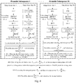
- Fig. 4 is a schematic diagram of a method of estimating the timing location detected jointly based on M preamble subsequences, and as shown, the method can be as follows.
- Each preamble subsequence is processed by using the LTE preamble detection algorithm as shown in Fig. 2 .
- Step 401 obtaining the detection window where the peak value of the correlation value power is located.
- the detection window corresponding to the m th preamble subsequence is WIN#m of which the length is Ncs.
- Step 404 performing the preamble detection P peak ′ ⁇ noise ′ 2 ⁇ V 2 , and estimating the timing location.
- Fig. 5 is a schematic diagram of a method of estimating the timing location detected jointly based on two 2-stage preamble subsequences, and as shown, the method can be as follows.
- the preamble subsequences #1 and #2 are processed by using the LTE preamble detection algorithm as shown in Fig. 2 .
- Step 501 obtaining the detection window where the peak value of the correlation value power is located.
- the corresponding detection windows obtained respectively by the preamble subsequences #1 and #2 are WIN #1 and WIN #2 of which the length is Ncs.
- Step 504 performing the preamble detection P peak ′ ⁇ noise ′ 2 ⁇ V 2 , and estimating the timing location.
- an embodiment of the present application further provides a device of estimating a timing location. Since the principle solving the problem of this device is similar to the method of estimating the timing location, the implementations of this device can refer to the implementations of the method, and the repeated description thereof will be omitted here.
- Fig. 6 is a structural schematic diagram of a first device of estimating a timing location, and as shown, the first device can includes:
- the detection window determining module 601 is further configured to: obtain a detection window where a peak value of a correlation value power of each preamble subsequence is located after estimating a Round Trip Time, RTT, timing location.
- Fig. 7 is a structural schematic diagram of a first terminal, and as shown, the terminal includes:
- the processor 700 is further configured to: obtain the detection window where the peak value of the correlation value power of each preamble subsequence is located after estimating the RTT timing location.
- the accumulating correlation value powers of all corresponding positions in the detection window obtained of each preamble subsequence to obtain a cumulative sum of the correlation value powers corresponding to each position includes:
- the bus architecture can include any numbers of interconnected buses and bridges, and specifically link various circuits of one or more processors represented by the processor 700 and the memory represented by the memory 720.
- the bus architecture can further link various other circuits such as peripheral device, voltage regulator and power management circuit, which are all well known in the art and thus will not be further described again herein.
- the bus interface provides an interface.
- the transceiver 710 can be a plurality of elements, i.e., include a transmitter and a receiver, and provide the units for communicating with various other devices over the transmission media.
- the user interface 730 can also be the interface capable of inter-connecting or exter-connecting with the required devices, and the connected devices include but not limited to keypad, display, loudspeaker, microphone, joystick and the like.
- the processor 700 is responsible for managing the bus architecture and general processing, and the memory 720 can store the data used by the processor 700 when performing the operations.
- Fig. 8 is a schematic diagram of an implementation process of a second method of estimating a timing location, and as shown, the second method can includes:
- the root index value u is configured at the network side.
- the mod(N_ZC) operation is omitted according to the ZC sequence characteristics.
- the method further includes: solving dT(m) jointly according to the relationship of K TA(m) values and the root index value u when the preamble sequence contains M preamble subsequences, wherein 2 ⁇ K ⁇ M.
- Base station side Assuming that the M-stage preamble sequence contains M preamble subsequences, the specific implementation can be as follows: Base station side:
- dT(m) can be solved jointly by using the relationship of M TA(m) values and the root index value u, and subtracted from the formula (7), to obtain the real timing location TA_real which does not affected by the normalized frequency offset df.
- dT(m) can be solved jointly by using the relationship of K (2 ⁇ K ⁇ M) TA(m) values and the root index value u.
- the joint solving can be implemented in the way which is well known by those skilled in the art, e.g., by the method of solving the system of linear equations.
- timing position estimation combining the 2-stage preamble subsequences with the ZC sequence characteristics
- TA1 and TA2 are the known quantities calculated by Fig. 2 , while TA_real, dT1 and dT2 are all the unknown quantities.
- dT1 and dT2 are calculated by the formula (12), and then substituted back into the formula (11) to obtain TA_real.
- an embodiment of the present application further provides a device of estimating a timing location. Since the principle solving the problem of this device is similar to the method of estimating the timing location, the implementations of this device can refer to the implementations of the method, and the repeated description thereof will be omitted here.
- Fig. 9 is a structural schematic diagram of a second device of estimating a timing location, and as shown, the second device can includes:
- the index value and frequency offset module is further configured to use the root index value u configured at the network side.
- the timing position estimation error module is further configured to solve dT(m) jointly according to the relationship of K TA(m) values and the root index value u when the preamble sequence contains M preamble subsequences, wherein 2 ⁇ K ⁇ M.
- Fig. 10 is a structural schematic diagram of a second terminal, and as shown, the terminal includes:
- the root index value u is configured at the network side.
- the mod(N_ZC) operation is omitted according to the ZC sequence characteristics.
- the processes further include: solving dT(m) jointly according to the relationship of K TA(m) values and the root index value u when the preamble sequence contains M preamble subsequences, wherein 2 ⁇ K ⁇ M.
- the bus architecture can include any numbers of interconnected buses and bridges, and specifically link various circuits of one or more processors represented by the processor 1000 and the memory represented by the memory 1020.
- the bus architecture can further link various other circuits such as peripheral device, voltage regulator and power management circuit, which are all well known in the art and thus will not be further described again herein.
- the bus interface provides an interface.
- the transceiver 1010 can be a plurality of elements, i.e., include a transmitter and a receiver, and provide the units for communicating with various other devices over the transmission media.
- the user interface 1030 can also be the interface capable of inter-connecting or exter-connecting with the required devices, and the connected devices include but not limited to keypad, display, loudspeaker, microphone, joystick and the like.
- the processor 1000 is responsible for managing the bus architecture and general processing, and the memory 1020 can store the data used by the processor 1000 when performing the operations.
- An embodiment of the invention provides a readable storage medium, which is a non-volatile storage medium and includes the program codes which are configured, when running on a computing device, to cause the computing device to perform the actions of any one of the methods estimating the timing location described above.
- the embodiments of the present application can provide methods, systems and computer program products.
- the present application can take the form of hardware embodiments alone, software embodiments alone, or embodiments combining the software and hardware aspects.
- the present application can take the form of computer program products implemented on one or more computer usable storage mediums (including but not limited to magnetic disk memories, optical memories and the like) containing computer usable program codes therein.
- These computer program instructions can also be stored in a computer readable memory which is capable of guiding the computer or another programmable data processing device to operate in a particular way, so that the instructions stored in the computer readable memory produce a manufacture including the instruction apparatus which implements the functions specified in one or more processes of the flow charts and/or one or more blocks of the block diagrams.
- These computer program instructions can also be loaded onto the computer or another programmable data processing device, so that a series of operation steps are performed on the computer or another programmable device to produce the computer-implemented processing.
- the instructions executed on the computer or another programmable device provide steps for implementing the functions specified in one or more processes of the flow charts and/or one or more blocks of the block diagrams.
Landscapes
- Engineering & Computer Science (AREA)
- Signal Processing (AREA)
- Computer Networks & Wireless Communication (AREA)
- Power Engineering (AREA)
- Synchronisation In Digital Transmission Systems (AREA)
- Mobile Radio Communication Systems (AREA)
Abstract
Description
- The application claims the priority from Chinese Patent Application No.
201710214517.4 - The present application relates to the field of wireless communication technologies and particularly to a method and a device of estimating a timing location.
- In the study of the NR (New Radio) PRACH (Physical Random Access Channel) preamble sequence of the 5G (5th Generation) mobile communication system, the designing scheme of the multi-stage (M-stage) preamble sequence is proposed in order to improve the detection performance of the preamble and reduce the collision probability of the short preamble sequence. Here, one M-stage preamble sequence consists of M preamble subsequences and used for one random-access Msg1 transmission. The UE (User Equipment) selects one M-stage preamble sequence from a set of predefined or network-configured M-stage preamble sequences, and transmits it over the single network-configured time-frequency resource. The network (gNB (next generation NodeB)/TRP (Transmission and Reception Point)) will detect the M preamble subsequences contained in the M-stage preamble sequence respectively over the time-frequency resources. The M-stage preamble sequence is detected correctly only if the M preamble subsequences are all detected correctly.
-
Fig. 1 is a schematic diagram of the designing scheme of the NR-PRACH M-stage preamble sequence when M=2, andFig. 1 shows an example of the designing scheme of the M-stage preamble sequence, wherein M=2, that is, one 2-stage preamble sequence consists of a combination of two preamble subsequences (denoted by Preamble-1 and Preamble-2 in the figure). Each of the two successive preamble subsequences (Preamble-1 and Preamble-2) has the respective CP (Cyclic Prefix), and the GT (Guard Time) is reserved at the end of the 2-stage preamble sequence. Each preamble subsequence is selected by the UE to obtain one 2-stage preamble sequence, and transmitted as the Msg1, which is detected respectively at the network side. The 2-stage preamble sequence is detected correctly only if the 2 preamble subsequences are both detected correctly. - The PRACH root sequence uses the ZC (Zadoff-Chu) sequence as the root sequence (ZC root sequence for short below). Since the precursor sequences of each cell are generated by the ZC root sequence through the Ncs (cyclic shift, i.e., zero correlation zone configuration), the number of the preamble sequences of each cell is 64 and the preamble sequence used by the UE is selected randomly or allocated by the gNB (next generation NodeB), there is a need to plan the ZC root sequence index correctly in order to reduce the too large interference of the preamble sequences between the adjacent cells. The purpose of the planning is to allocate a ZC root sequence index to the cells so as to ensure that the preamble sequences generated by the adjacent cells using this index are different, to thereby reduce the mutual interference produced by the adjacent cells using the same preamble sequence.
- The root index value is defined as the Zadoff-Chu (ZC sequence) of u th, as shown by the formula of:


-
Fig. 2 is a schematic diagram of the LTE preamble detection algorithm in the prior art, and as shown inFig. 2 , the main steps of the LTE preamble detection algorithm in the prior art are as follows: - Step 201: calculating the correlation values of the local preamble sequences and the received signals on all the receiving antennas, which is generally implemented by using the frequency-domain FFT (Fast Fourier Transform) multiplication method, as shown by the formula of:

- Step 202: calculating the correlation value powers |R 1(k)|2 on all the receiving antennas;
- Step 203: accumulating and summing for all the antennas;
- Step 204: calculating the peak value Ppeak of the correlation value power, and estimating the noise
power 
- Step 205: judging based on the ratio Dcor of the peak value of the correlation value power to the noise power and the predefined threshold value V 1, judging a preamble is transmitted if Dcor is greater than or equal to V 1 and obtaining the timing position τpeak of the RTT (Round Trip Time) according to the position estimation of the peak value Ppeak ; and judging no preamble is transmitted if Dcor is less than V 1 ;

- The deficiencies of the prior art include:
- 1. the current M-stage preamble sequence scheme has the problem of the larger influence on the estimation accuracy of the timing position in the case of the larger frequency offset;
- 2. As can be seen from the signal processing theory, the frequency deviation (i.e., frequency offset) has a certain effect on the estimation accuracy of the timing position. If there is a large frequency offset between the received preamble and the local preamble, the self-correlative peak value may provide the imprecise PRACH timing position estimation. That is, TA=TA_real+dT, where dT is the error of the timing position estimation caused by the frequency offset.
- The present application provides a method and a device of estimating a timing location, so as to solve the problem that the current M-stage preamble sequence scheme has a larger effect on the estimation accuracy of the timing position in the case of the larger frequency offset.
- In a first aspect, an embodiment of the present application provides a method of estimating a timing location, which includes:
- obtaining, for each preamble subsequence, a detection window where a peak value of a correlation value power of each preamble subsequence is located;
- accumulating correlation value powers of all corresponding positions in the detection window obtained of each preamble subsequence to obtain a cumulative sum of the correlation value powers corresponding to each position, wherein the correlation value powers of each preamble subsequence used for the accumulation are correlation value powers in a detection window where a peak value of a respective correlation value power of each preamble subsequence is located;
- determining a peak power and a noise power according to the cumulative sum of the correlation value powers;
- estimating the timing location according to the peak power and the noise power.
- Optionally, the obtaining a detection window where a peak value of a correlation value power of each preamble subsequence is located, further includes:
obtaining a detection window where a peak value of a correlation value power of each preamble subsequence is located after estimating a Round Trip Time, RTT, timing location. - Optionally, the accumulating the correlation value powers of all corresponding positions in the detection window obtained of each preamble subsequence to obtain the cumulative sum of the correlation value powers corresponding to each position, includes:
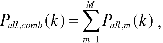
- if there are M preamble subsequences, the cumulative sum of the correlation value powers of the M preamble subsequences is:

- In a second aspect, an embodiment of the present application provides a device of estimating a timing location, which includes:
- a detection window determining module configured to obtain, for each preamble subsequence, a detection window where a peak value of a correlation value power of each preamble subsequence is located;
- a correlation value power cumulative sum module configured to accumulate correlation value powers of all corresponding positions in the detection window obtained of each preamble subsequence to obtain a cumulative sum of the correlation value powers corresponding to each position, wherein the correlation value powers of each preamble subsequence used for the accumulation are correlation value powers in a detection window where a peak value of a respective correlation value power of each preamble subsequence is located;
- a power determining module configured to determine a peak power and a noise power according to the cumulative sum of the correlation value powers;
- a timing location estimating module configured to estimate the timing location according to the peak power and the noise power.
- Optionally, the detection window determining module is further configured to:
obtain a detection window where a peak value of a correlation value power of each preamble subsequence is located after estimating a Round Trip Time, RTT, timing location. - Optionally, the correlation value power cumulative sum module is further configured so that when accumulating the correlation value powers of all corresponding positions in the detection window obtained of each preamble subsequence to obtain the cumulative sum of the correlation value powers corresponding to each position, if there are M preamble subsequences, the cumulative sum of the correlation value powers of the M preamble subsequences is:

- The present application has the following beneficial effects.
- In the technical solution provided by the embodiments of the present application, the peak power and the noise power for determining the timing position are derived from the cumulative sum of the self-correlation value powers while the cumulative sum of the correlation value powers is the cumulative sum of the correlation value powers of all the preamble subsequences, where for each preamble subsequence, this value is derived from the correlation value power of each preamble subsequence within the detection window where the peak value of the respective correlation value power is located, so the peak power and the noise power for determining the timing position has corrected the error caused by the frequency offset. Therefore, with this solution, the problem that the current M-stage preamble sequence scheme has a larger effect on the estimation accuracy of the timing position in the case of the larger frequency offset can be solved.
- The present application provides a method and a device of estimating a timing location, so as to solve the problem that the self-correlative peak value may provide the imprecise PRACH timing position estimation when there is the large frequency offset between the received preamble and the local preamble.
- In a third aspect, an embodiment of the present application provides a method of estimating a timing location, which includes:
- estimating the timing location TA of each preamble subsequence according to a peak value of a correlation value power and a noise power detected;
- determining a root index value u and a normalized frequency offset df of each preamble subsequence;
- determining a timing position estimation error dT caused by the frequency offset according to the normalized frequency offset df and the root index value u of each preamble subsequence;
- determining a real timing position TA_real according to the timing location TA and the timing position estimation error dT of each preamble subsequence.
- Optionally, the root index value u is configured at the network side.
- Optionally, determining a timing position estimation error dT caused by the frequency offset according to the normalized frequency offset df and the root index value u of each preamble subsequence by way of:
dT(m) = df/u(m), wherein dT(m) is the timing position estimation error of the mth preamble subsequence, and u(m) is the root index value of the mth preamble subsequence. - Optionally, when dT(m) = df/u(m), the mod(N_ZC) operation is omitted according to the ZC sequence characteristics.
- Optionally, the method further includes:
solving dT(m) jointly according to the relationship of K TA(m) values and the root index value u when the preamble sequence contains M preamble subsequences, wherein 2≤K≤ M. - In a fourth aspect, an embodiment of the present application provides a device of estimating a timing location, which includes:
- a timing location detecting module configured to estimate the timing location TA of each preamble subsequence according to a peak value of a correlation value power and a noise power detected;
- a index value and frequency offset module configured to determine a root index value u and a normalized frequency offset df of each preamble subsequence;
- a timing position estimation error module configured to determine a timing position estimation error dT caused by the frequency offset according to the normalized frequency offset df and the root index value u of each preamble subsequence;
- a real timing position module configured to determine a real timing position TA_real according to the timing location TA and the timing position estimation error dT of each preamble subsequence.
- Optionally, the index value and frequency offset module is further configured to use the root index value u configured at the network side.
- Optionally, the timing position estimation error module is further configured to determine a timing position estimation error dT caused by the frequency offset according to the normalized frequency offset df and the root index value u of each preamble subsequence by way of:
dT(m) = df/u(m), wherein dT(m) is the timing position estimation error of the mth preamble subsequence, and u(m) is the root index value of the mth preamble subsequence. - Optionally, the timing position estimation error module is further configured to omit the mod(N_ZC) operation according to the ZC sequence characteristics when dT(m) = df/u(m).
- Optionally, the timing position estimation error module is further configured to solve dT(m) jointly according to the relationship of K TA(m) values and the root index value u when the preamble sequence contains M preamble subsequences, wherein 2≤K≤M.
- In a fifth aspect, an embodiment of the present application provides a device of estimating a timing location, which includes:
- a processor configured to read programs in a memory to perform processes of:
- obtaining, for each preamble subsequence, a detection window where a peak value of a correlation value power of each preamble subsequence is located;
- accumulating correlation value powers of all corresponding positions in the detection window obtained of each preamble subsequence to obtain a cumulative sum of the correlation value powers corresponding to each position, wherein the correlation value powers of each preamble subsequence used for the accumulation are correlation value powers in a detection window where a peak value of a respective correlation value power of each preamble subsequence is located;
- determining a peak power and a noise power according to the cumulative sum of the correlation value powers;
- estimating the timing location according to the peak power and the noise power;
- a transceiver configured to receive and transmit data under the control of the processor to perform processes of:
receiving and transmitting the data according to the processor's requirement. - Optionally, the processor is further configured to:
obtain a detection window where a peak value of a correlation value power of each preamble subsequence is located after estimating a Round Trip Time, RTT, timing location. - Optionally, the processor is further configured so that when accumulating correlation value powers of all corresponding positions in the detection window obtained of each preamble subsequence to obtain a cumulative sum of the correlation value powers corresponding to each position, if there are M preamble subsequences, the cumulative sum of the correlation value powers of the M preamble subsequences is:

- In a sixth aspect, an embodiment of the present application provides a device of estimating a timing location, which includes:
- a processor configured to read programs in a memory to perform processes of:
- estimating the timing location TA of each preamble subsequence according to a peak value of a correlation value power and a noise power detected;
- determining a root index value u and a normalized frequency offset df of each preamble subsequence;
- determining a timing position estimation error dT caused by the frequency offset according to the normalized frequency offset df and the root index value u of each preamble subsequence;
- determining a real timing position TA_real according to the timing location TA and the timing position estimation error dT of each preamble subsequence;
- a transceiver configured to receive and transmit data under the control of the processor to perform processes of:
receiving and transmitting the data according to the processor's requirement. - Optionally, the root index value u is configured at the network side.
- Optionally, the processor is further configured to determine a timing position estimation error dT caused by the frequency offset according to the normalized frequency offset df and the root index value u of each preamble subsequence by way of:
dT(m) = df/u(m), wherein dT(m) is the timing position estimation error of the mth preamble subsequence, and u(m) is the root index value of the mth preamble subsequence. - Optionally, the processor is further configured to omit the mod(N_ZC) operation according to the ZC sequence characteristics when dT(m) = df/u(m).
- Optionally, the processor is further configured to solve dT(m) jointly according to the relationship of K TA(m) values and the root index value u when the preamble sequence contains M preamble subsequences, wherein 2≤K≤M.
- In a seventh aspect, an embodiment of the present application provides a readable storage medium of a cache synchronization exception device, including the program codes which are configured, when running on a computing device, to cause the computing device to perform any solution of the first aspect or any solution of the third aspect described above.
- The present application has the following beneficial effects.
- In the technical solutions provided by the embodiments of the present application, for the timing position estimation error between the real timing position and the measured timing position, since the timing position estimation error caused by the frequency offset is determined by using the normalized frequency offset df and the root index value u according to the ZC sequence characteristics, the problem that the self-correlative peak value may provide the imprecise PRACH timing position estimation when there is the large frequency offset between the received preamble and the local preamble can be solved.
- The accompanying drawings illustrated here are used to provide the further understanding of the present application and constitute a part of the present application, and the schematic embodiments of the present application and the illustration thereof are used to explain the present application but not limit the present application improperly. In the accompanying drawings:
-
Fig. 1 is a schematic diagram of the designing scheme of the NR-PRACH M-stage preamble sequence when M=2 in the background art; -
Fig. 2 is a schematic diagram of the existing LTE preamble detection algorithm in the background art; -
Fig. 3 is a schematic diagram of an implementation process of a first method of estimating a timing location in an embodiment of the present application; -
Fig. 4 is a schematic diagram of a method of estimating the timing location detected jointly based on M preamble subsequences in an embodiment of the present application; -
Fig. 5 is a schematic diagram of a method of estimating the timing location detected jointly based on two 2-stage preamble subsequences in an embodiment of the present application; -
Fig. 6 is a structural schematic diagram of a first device of estimating a timing location in an embodiment of the present application; -
Fig. 7 is a structural schematic diagram of a first terminal in an embodiment of the present application; -
Fig. 8 is a schematic diagram of an implementation process of a second method of estimating a timing location in an embodiment of the present application; -
Fig. 9 is a structural schematic diagram of a second device of estimating a timing location in an embodiment of the present application; -
Fig. 10 is a structural schematic diagram of a second terminal in an embodiment of the present application. - The embodiments of the present application will provide a detection scheme of the M-stage preamble sequence, so as to solve the problem of the lower timing position estimation precision in the case of the larger frequency offset. For the first point: the problem that the current M-stage preamble sequence scheme has a larger effect on the estimation precision of the timing position in the case of the larger frequency offset, the first solution will be provided in the embodiments to solve this problem; and for the second point: the problem that the self-correlative peak value may provide the imprecise PRACH timing position estimation if there is a large frequency offset between the received preamble and the local preamble, the second solution will be provided in the embodiments to solve this problem. The specific embodiments of the present application will be illustrated below in combination with the drawings.
-
Fig. 3 is a schematic diagram of an implementation process of a first method of estimating a timing location, and as shown, the first method can includes: - Step 301: obtaining, for each preamble subsequence, the detection window where the peak value of the correlation value power of each preamble subsequence is located;
- Step 302: accumulating the correlation value powers of all the corresponding positions in the detection window obtained of each preamble subsequence to obtain the cumulative sum of the correlation value powers corresponding to each position, wherein the correlation value powers of each preamble subsequence used for the accumulation are the correlation value powers in the detection window where the peak value of the respective correlation value power is located;
- Step 303: determining the peak power and the noise power according to the cumulative sum of the correlation value powers;
- Step 304: estimating the timing location according to the peak power and the noise power.
- Optionally, the detection window where the peak value of the correlation value power of each preamble subsequence is located is obtained after the Round Trip Time, RTT, timing location is estimated.
- In an implementation, the accumulating the correlation value powers of all the corresponding positions in the detection window obtained of each preamble subsequence to obtain the cumulative sum of the correlation value powers corresponding to each position, includes:
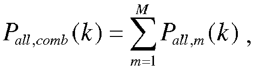
- if there are M preamble subsequences, the cumulative sum of the correlation value powers of the M preamble subsequences is:

- Assuming that the M-stage preamble sequence contains M preamble subsequences, the specific implementation can be as follows.
-
Fig. 4 is a schematic diagram of a method of estimating the timing location detected jointly based on M preamble subsequences, and as shown, the method can be as follows. - Each preamble subsequence is processed by using the LTE preamble detection algorithm as shown in
Fig. 2 . - Step 401: obtaining the detection window where the peak value of the correlation value power is located.
- Specifically, for example, the detection window corresponding to the mth preamble subsequence is WIN#m of which the length is Ncs.
- Step 402: calculating the cumulative sum of the correlation value powers of the M preamble subsequences within the respective peak detection windows, which is as follows:

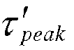
- Step 403: calculating the new peak power


- Step 404: performing the preamble detection

- Specifically, it is judged based on the ratio


- The following description is made based on the instance of two 2-stage preamble subsequences.
-
Fig. 5 is a schematic diagram of a method of estimating the timing location detected jointly based on two 2-stage preamble subsequences, and as shown, the method can be as follows. - The
preamble subsequences # 1 and #2 are processed by using the LTE preamble detection algorithm as shown inFig. 2 . - Step 501: obtaining the detection window where the peak value of the correlation value power is located.
- For example, the corresponding detection windows obtained respectively by the
preamble subsequences # 1 and #2 areWIN # 1 andWIN # 2 of which the length is Ncs. - Step 502: calculating the cumulative sum of the correlation value powers of two preamble subsequences within the respective peak detection windows:

preamble subsequences # 1 and #2 are located respectively, and 1≤k≤Ncs. - Step 503: calculating the new peak power


- Step 504: performing the preamble detection

- Specifically, it is judged based on the ratio



- Based upon the same inventive concept, an embodiment of the present application further provides a device of estimating a timing location. Since the principle solving the problem of this device is similar to the method of estimating the timing location, the implementations of this device can refer to the implementations of the method, and the repeated description thereof will be omitted here.
-
Fig. 6 is a structural schematic diagram of a first device of estimating a timing location, and as shown, the first device can includes: - a detection
window determining module 601 configured to obtain, for each preamble subsequence, the detection window where the peak value of the correlation value power of each preamble subsequence is located; - a correlation value power
cumulative sum module 602 configured to accumulate the correlation value powers of all the corresponding positions in the detection window obtained of each preamble subsequence to obtain the cumulative sum of the correlation value powers corresponding to each position, wherein the correlation value powers of each preamble subsequence used for the accumulation are the correlation value powers in the detection window where the peak value of the respective correlation value power is located; - a
power determining module 603 configured to determine the peak power and the noise power according to the cumulative sum of the correlation value powers; - a timing
location estimating module 604 configured to estimate the timing location according to the peak power and the noise power. - Optionally, the detection
window determining module 601 is further configured to:
obtain a detection window where a peak value of a correlation value power of each preamble subsequence is located after estimating a Round Trip Time, RTT, timing location. - In an implementation, the correlation value power cumulative sum module is further configured so that when accumulating correlation value powers of all corresponding positions in the detection window obtained of each preamble subsequence to obtain the cumulative sum of the correlation value powers corresponding to each position, if there are M preamble subsequences, the cumulative sum of the correlation value powers of the M preamble subsequences is:
- When the technical solution provided by the embodiment of the present application is implemented, it can be implemented in such way as follows.
-
Fig. 7 is a structural schematic diagram of a first terminal, and as shown, the terminal includes: - a
processor 700 configured to read the programs in amemory 720 to perform the processes of:- obtaining, for each preamble subsequence, the detection window where the peak value of the correlation value power of each preamble subsequence is located;
- accumulating the correlation value powers of all the corresponding positions in the detection window obtained of each preamble subsequence to obtain the cumulative sum of the correlation value powers corresponding to each position, wherein the correlation value powers of each preamble subsequence used for the accumulation are the correlation value powers in the detection window where the peak value of the respective correlation value power is located;
- determining the peak power and the noise power according to the cumulative sum of the correlation value powers;
- estimating the timing location according to the peak power and the noise power;
- a
transceiver 710 configured to receive and transmit the data under the control of theprocessor 700 to perform the processes of:
receiving and transmitting the data according to the processor's requirement. - Optionally, the
processor 700 is further configured to:
obtain the detection window where the peak value of the correlation value power of each preamble subsequence is located after estimating the RTT timing location. - In an implementation, the accumulating correlation value powers of all corresponding positions in the detection window obtained of each preamble subsequence to obtain a cumulative sum of the correlation value powers corresponding to each position, includes:
- if there are M preamble subsequences, the cumulative sum of the correlation value powers of the M preamble subsequences is:

- Here, in
Fig. 7 , the bus architecture can include any numbers of interconnected buses and bridges, and specifically link various circuits of one or more processors represented by theprocessor 700 and the memory represented by thememory 720. The bus architecture can further link various other circuits such as peripheral device, voltage regulator and power management circuit, which are all well known in the art and thus will not be further described again herein. The bus interface provides an interface. Thetransceiver 710 can be a plurality of elements, i.e., include a transmitter and a receiver, and provide the units for communicating with various other devices over the transmission media. For different user equipments, theuser interface 730 can also be the interface capable of inter-connecting or exter-connecting with the required devices, and the connected devices include but not limited to keypad, display, loudspeaker, microphone, joystick and the like. - The
processor 700 is responsible for managing the bus architecture and general processing, and thememory 720 can store the data used by theprocessor 700 when performing the operations. -
Fig. 8 is a schematic diagram of an implementation process of a second method of estimating a timing location, and as shown, the second method can includes: - Step 801: estimating the timing location TA of each preamble subsequence according to the peak value of the correlation value power and the noise power detected;
- Step 802: determining the root index value u and the normalized frequency offset df of each preamble subsequence;
- Step 803: determining the timing position estimation error dT caused by the frequency offset according to the normalized frequency offset df and the root index value u of each preamble subsequence;
- Step 804: determining the real timing position TA_real according to the timing location TA and the timing position estimation error dT of each preamble subsequence.
- In an implementation, the root index value u is configured at the network side.
- In an implementation, the timing position estimation error dT caused by the frequency offset can be determined according to the normalized frequency offset df and the root index value u of each preamble subsequence by way of:
dT(m) = df/u(m), wherein dT(m) is the timing position estimation error of the mth preamble subsequence, and u(m) is the root index value of the mth preamble subsequence. - In an implementation, when dT(m) = df/u(m), the mod(N_ZC) operation is omitted according to the ZC sequence characteristics.
- In an implementation, the method further includes:
solving dT(m) jointly according to the relationship of K TA(m) values and the root index value u when the preamble sequence contains M preamble subsequences, wherein 2≤K≤ M. - Assuming that the M-stage preamble sequence contains M preamble subsequences, the specific implementation can be as follows:
Base station side: - the base station configures M different root sequence index values u respectively, e.g., u(1), u(2), ···, u(M).
- Terminal side:
considering that the time interval occupied by the PRACH symbols is relatively short, it is assumed that the normalized frequency offsets of all the M preamble subsequences are the same and denoted as df; and the M preamble subsequences use different root sequence indexes u(1), u(2), ···, u(M). - The LTE preamble detection algorithm as shown in
Fig. 2 is used for the processing, and the estimated timing locations obtained respectively for the individual preamble subsequences are TA(1), TA(2), ···, TA(M), which are represented by:
- As can be seen from the ZC sequence characteristics:

- According to the formulas (7) and (8), dT(m) can be solved jointly by using the relationship of M TA(m) values and the root index value u, and subtracted from the formula (7), to obtain the real timing location TA_real which does not affected by the normalized frequency offset df.
- At the same time, in order to reduce the processing complexity, dT(m) can be solved jointly by using the relationship of K (2≤K≤M) TA(m) values and the root index value u.
- The joint solving can be implemented in the way which is well known by those skilled in the art, e.g., by the method of solving the system of linear equations.
- The following description is made based on the instance of the 2-stage preamble subsequences.
- The implementation of the timing position estimation combining the 2-stage preamble subsequences with the ZC sequence characteristics will be illustrated in this example.
- It is assumed that two 2-stage preamble subsequences have two root index values u1 and u2 respectively, and the TA estimations (denoted as TA1 and TA2) can be obtained by detecting the two preamble subsequences respectively, and include the estimation errors dT1 and dT2 caused by the same frequency offset df respectively. That is:

- dT1 and dT2 can be obtained according to the ZC sequence characteristics dT1=df/u1, dT2=df/u2 as well as TA1 and TA2 obtained by the detection method as shown in
Fig. 2 :
- In an implementation, in formula (11), TA1 and TA2 are the known quantities calculated by
Fig. 2 , while TA_real, dT1 and dT2 are all the unknown quantities. Thus, dT1 and dT2 are calculated by the formula (12), and then substituted back into the formula (11) to obtain TA_real. - After dT1 and dT2 are obtained, the estimated value TA_real of the timing location which is more precise and not affected by the frequency offset df can be obtained by TA_real=TA1-dT1, TA_real=TA2-dT2 or TA_real = ((TA1-dT1) + (TA2-dT2))/2.
- Based upon the same inventive concept, an embodiment of the present application further provides a device of estimating a timing location. Since the principle solving the problem of this device is similar to the method of estimating the timing location, the implementations of this device can refer to the implementations of the method, and the repeated description thereof will be omitted here.
-
Fig. 9 is a structural schematic diagram of a second device of estimating a timing location, and as shown, the second device can includes: - a timing
location detecting module 901 configured to estimate the timing location TA of each preamble subsequence according to the peak value of the correlation value power and the noise power detected; - a index value and frequency offset
module 902 configured to determine the root index value u and the normalized frequency offset df of each preamble subsequence; - a timing position
estimation error module 903 configured to determine the timing position estimation error dT caused by the frequency offset according to the normalized frequency offset df and the root index value u of each preamble subsequence; - a real
timing position module 904 configured to determine the real timing position TA_real according to the timing location TA and the timing position estimation error dT of each preamble subsequence. - In an implementation, the index value and frequency offset module is further configured to use the root index value u configured at the network side.
- In an implementation, the timing position estimation error module is further configured to determine the timing position estimation error dT caused by the frequency offset according to the normalized frequency offset df and the root index value u of each preamble subsequence by way of:
dT(m) = df/u(m), wherein dT(m) is the timing position estimation error of the mth preamble subsequence, and u(m) is the root index value of the mth preamble subsequence. - In an implementation, the timing position estimation error module is further configured to omit the mod(N_ZC) operation according to the ZC sequence characteristics when dT(m) = df/u(m).
- In an implementation, the timing position estimation error module is further configured to solve dT(m) jointly according to the relationship of K TA(m) values and the root index value u when the preamble sequence contains M preamble subsequences, wherein 2≤K ≤M.
- For the sake of description, all the parts of the above-mentioned device are divided into various modules or units by function, which are described respectively. Of course, the functions of the various modules or units can be implemented in the same one or more softwares or hardware when the present application is implemented.
- When the technical solution provided by the embodiment of the present application is implemented, it can be implemented in such way as follows.
-
Fig. 10 is a structural schematic diagram of a second terminal, and as shown, the terminal includes: - a
processor 1000 configured to read the programs in amemory 1020 to perform the processes of:- estimating the timing location TA of each preamble subsequence according to the peak value of the correlation value power and the noise power detected;
- determining the root index value u and the normalized frequency offset df of each preamble subsequence;
- determining the timing position estimation error dT caused by the frequency offset according to the normalized frequency offset df and the root index value u of each preamble subsequence;
- determining the real timing position TA_real according to the timing location TA and the timing position estimation error dT of each preamble subsequence;
- a
transceiver 1010 configured to receive and transmit the data under the control of theprocessor 1000 to perform the processes of:
receiving and transmitting the data according to the processor's requirement. - In an implementation, the root index value u is configured at the network side.
- In an implementation, the timing position estimation error dT caused by the frequency offset is determined according to the normalized frequency offset df and the root index value u of each preamble subsequence by way of:
dT(m) = df/u(m), wherein dT(m) is the timing position estimation error of the mth preamble subsequence, and u(m) is the root index value of the mth preamble subsequence. - In an implementation, when dT(m) = df/u(m), the mod(N_ZC) operation is omitted according to the ZC sequence characteristics.
- In an implementation, the processes further include:
solving dT(m) jointly according to the relationship of K TA(m) values and the root index value u when the preamble sequence contains M preamble subsequences, wherein 2≤K≤ M. - Here, in
Fig. 10 , the bus architecture can include any numbers of interconnected buses and bridges, and specifically link various circuits of one or more processors represented by theprocessor 1000 and the memory represented by thememory 1020. The bus architecture can further link various other circuits such as peripheral device, voltage regulator and power management circuit, which are all well known in the art and thus will not be further described again herein. The bus interface provides an interface. Thetransceiver 1010 can be a plurality of elements, i.e., include a transmitter and a receiver, and provide the units for communicating with various other devices over the transmission media. For different user equipments, theuser interface 1030 can also be the interface capable of inter-connecting or exter-connecting with the required devices, and the connected devices include but not limited to keypad, display, loudspeaker, microphone, joystick and the like. - The
processor 1000 is responsible for managing the bus architecture and general processing, and thememory 1020 can store the data used by theprocessor 1000 when performing the operations. - An embodiment of the invention provides a readable storage medium, which is a non-volatile storage medium and includes the program codes which are configured, when running on a computing device, to cause the computing device to perform the actions of any one of the methods estimating the timing location described above.
- It should be understood by those skilled in the art that the embodiments of the present application can provide methods, systems and computer program products. Thus the present application can take the form of hardware embodiments alone, software embodiments alone, or embodiments combining the software and hardware aspects. Also the present application can take the form of computer program products implemented on one or more computer usable storage mediums (including but not limited to magnetic disk memories, optical memories and the like) containing computer usable program codes therein.
- The present application is described by reference to the flow charts and/or the block diagrams of the methods, the devices (systems) and the computer program products according to the embodiments of the present application. It should be understood that each process and/or block in the flow charts and/or the block diagrams, and a combination of processes and/or blocks in the flow charts and/or the block diagrams can be implemented by the computer program instructions. These computer program instructions can be provided to a general-purpose computer, a dedicated computer, an embedded processor, or a processor of another programmable data processing device to produce a machine, so that an apparatus for implementing the functions specified in one or more processes of the flow charts and/or one or more blocks of the block diagrams is produced by the instructions executed by the computer or the processor of another programmable data processing device.
- These computer program instructions can also be stored in a computer readable memory which is capable of guiding the computer or another programmable data processing device to operate in a particular way, so that the instructions stored in the computer readable memory produce a manufacture including the instruction apparatus which implements the functions specified in one or more processes of the flow charts and/or one or more blocks of the block diagrams.
- These computer program instructions can also be loaded onto the computer or another programmable data processing device, so that a series of operation steps are performed on the computer or another programmable device to produce the computer-implemented processing. Thus the instructions executed on the computer or another programmable device provide steps for implementing the functions specified in one or more processes of the flow charts and/or one or more blocks of the block diagrams.
- Evidently those skilled in the art can make various modifications and variations to the present application without departing from the spirit and scope of the present application. Thus the present application is also intended to encompass these modifications and variations therein as long as these modifications and variations to the present application come into the scope of the claims of the present application and their equivalents.
Claims (25)
- A method of estimating a timing location, the method comprises:obtaining, for each preamble subsequence, a detection window where a peak value of a correlation value power of each preamble subsequence is located;accumulating correlation value powers of all corresponding positions in the detection window obtained of each preamble subsequence to obtain a cumulative sum of the correlation value powers corresponding to each position, wherein the correlation value powers of each preamble subsequence used for the accumulation are correlation value powers in a detection window where a peak value of a respective correlation value power of each preamble subsequence is located;determining a peak power and a noise power according to the cumulative sum of the correlation value powers;estimating the timing location according to the peak power and the noise power.
- The method of claim 1, wherein the obtaining a detection window where a peak value of a correlation value power of each preamble subsequence is located, further comprises:
obtaining a detection window where a peak value of a correlation value power of each preamble subsequence is located after estimating a Round Trip Time, RTT, timing location. - The method of claim 1, wherein the accumulating correlation value powers of all corresponding positions in the detection window obtained of each preamble subsequence to obtain a cumulative sum of the correlation value powers corresponding to each position, comprises:
if there are M preamble subsequences, the cumulative sum of the correlation value powers of the M preamble subsequences is:
- A device of estimating a timing location, the device comprises:a detection window determining module configured to obtain, for each preamble subsequence, a detection window where a peak value of a correlation value power of each preamble subsequence is located;a correlation value power cumulative sum module configured to accumulate correlation value powers of all corresponding positions in the detection window obtained of each preamble subsequence to obtain a cumulative sum of the correlation value powers corresponding to each position, wherein the correlation value powers of each preamble subsequence used for the accumulation are correlation value powers in a detection window where a peak value of a respective correlation value power of each preamble subsequence is located;a power determining module configured to determine a peak power and a noise power according to the cumulative sum of the correlation value powers;a timing location estimating module configured to estimate the timing location according to the peak power and the noise power.
- The device of claim 4, wherein the detection window determining module is further configured to:
obtain a detection window where a peak value of a correlation value power of each preamble subsequence is located after estimating a Round Trip Time, RTT, timing location. - The device of claim 4, wherein the correlation value power cumulative sum module is further configured so that when accumulating correlation value powers of all corresponding positions in the detection window obtained of each preamble subsequence to obtain a cumulative sum of the correlation value powers corresponding to each position, if there are M preamble subsequences, the cumulative sum of the correlation value powers of the M preamble subsequences is:

- A method of estimating a timing location, the method comprises:estimating the timing location TA of each preamble subsequence according to a peak value of a correlation value power and a noise power detected;determining a root index value u and a normalized frequency offset df of each preamble subsequence;determining a timing position estimation error dT caused by the frequency offset according to the normalized frequency offset df and the root index value u of each preamble subsequence;determining a real timing position TA_real according to the timing location TA and the timing position estimation error dT of each preamble subsequence.
- The method of claim 7, wherein the root index value u is configured at a network side.
- The method of claim 7, wherein determining a timing position estimation error dT caused by the frequency offset according to the normalized frequency offset df and the root index value u of each preamble subsequence by way of:
dT(m) = df/u(m), wherein dT(m) is a timing position estimation error of an mth preamble subsequence, and u(m) is a root index value of the mth preamble subsequence. - The method of claim 9, wherein when dT(m) = df/u(m), the mod(N_ZC) operation is omitted according to ZC sequence characteristics.
- The method of any one of claims 7 to 10, the method further comprises:
solving dT(m) jointly according to the relationship of K TA(m) values and the root index value u when the preamble sequence contains M preamble subsequences, wherein 2≤K≤M. - A device of estimating a timing location, the device comprises:a timing location detecting module configured to estimate the timing location TA of each preamble subsequence according to a peak value of a correlation value power and a noise power detected;a index value and frequency offset module configured to determine a root index value u and a normalized frequency offset df of each preamble subsequence;a timing position estimation error module configured to determine a timing position estimation error dT caused by the frequency offset according to the normalized frequency offset df and the root index value u of each preamble subsequence;a real timing position module configured to determine a real timing position TA_real according to the timing location TA and the timing position estimation error dT of each preamble subsequence.
- The device of claim 12, wherein the index value and frequency offset module is further configured to use the root index value u configured at a network side.
- The device of claim 12, wherein the timing position estimation error module is further configured to determine a timing position estimation error dT caused by the frequency offset according to the normalized frequency offset df and the root index value u of each preamble subsequence by way of:
dT(m) = df/u(m), wherein dT(m) is a timing position estimation error of an mth preamble subsequence, and u(m) is a root index value of the mth preamble subsequence. - The device of claim 14, wherein the timing position estimation error module is further configured to omit the mod(N_ZC) operation according to ZC sequence characteristics when dT(m) = df/u(m).
- The device of any one of claims 12 to 15, wherein the timing position estimation error module is further configured to solve dT(m) jointly according to the relationship of K TA(m) values and the root index value u when a preamble sequence contains M preamble subsequences, wherein 2≤K≤M.
- A device of estimating a timing location, the device comprises:a processor configured to read programs in a memory to perform processes of:obtaining, for each preamble subsequence, a detection window where a peak value of a correlation value power of each preamble subsequence is located;accumulating correlation value powers of all corresponding positions in the detection window obtained of each preamble subsequence to obtain a cumulative sum of the correlation value powers corresponding to each position, wherein the correlation value powers of each preamble subsequence used for the accumulation are correlation value powers in a detection window where a peak value of a respective correlation value power of each preamble subsequence is located;determining a peak power and a noise power according to the cumulative sum of the correlation value powers;estimating the timing location according to the peak power and the noise power;a transceiver configured to receive and transmit data under the control of the processor to perform processes of:
receiving and transmitting data according to the processor's requirement. - The device of claim 17, wherein the processor is further configured to:
obtain a detection window where a peak value of a correlation value power of each preamble subsequence is located after estimating a Round Trip Time, RTT, timing location. - The device of claim 17, wherein the processor is further configured so that when accumulating correlation value powers of all corresponding positions in the detection window obtained of each preamble subsequence to obtain a cumulative sum of the correlation value powers corresponding to each position, if there are M preamble subsequences, the cumulative sum of the correlation value powers of the M preamble subsequences is:
- A device of estimating a timing location, the device comprises:a processor configured to read programs in a memory to perform processes of:estimating the timing location TA of each preamble subsequence according to a peak value of a correlation value power and a noise power detected;determining a root index value u and a normalized frequency offset df of each preamble subsequence;determining a timing position estimation error dT caused by the frequency offset according to the normalized frequency offset df and the root index value u of each preamble subsequence;determining a real timing position TA_real according to the timing location TA and the timing position estimation error dT of each preamble subsequence;a transceiver configured to receive and transmit data under the control of the processor to perform processes of:
receiving and transmitting data according to the processor's requirement. - The device of claim 20, wherein the root index value u is configured at a network side.
- The device of claim 20, wherein the processor is further configured to determine a timing position estimation error dT caused by the frequency offset according to the normalized frequency offset df and the root index value u of each preamble subsequence by way of:
dT(m) = df/u(m), wherein dT(m) is a timing position estimation error of an mth preamble subsequence, and u(m) is a root index value of the mth preamble subsequence. - The device of claim 22, wherein the processor is further configured to omit the mod(N_ZC) operation according to ZC sequence characteristics when dT(m) = df/u(m).
- The device of any one of claims 20 to 23, wherein the processor is further configured to solve dT(m) jointly according to the relationship of K TA(m) values and the root index value u when a preamble sequence contains M preamble subsequences, wherein 2≤K≤M.
- A readable storage medium of a cache synchronization exception device, characterized in that, the readable storage medium comprises program codes which are configured, when running on a computing device, to cause the computing device to perform the steps of the method of any one of claims 1 to 3 or the steps of the method of any one of claims 7 to 11.
Applications Claiming Priority (2)
| Application Number | Priority Date | Filing Date | Title |
|---|---|---|---|
| CN201710214517.4A CN108683482B (en) | 2017-04-01 | 2017-04-01 | Method and device for estimating timing position |
| PCT/CN2018/079598 WO2018177160A1 (en) | 2017-04-01 | 2018-03-20 | Method and device for estimating timing location |
Publications (3)
| Publication Number | Publication Date |
|---|---|
| EP3609110A1 true EP3609110A1 (en) | 2020-02-12 |
| EP3609110A4 EP3609110A4 (en) | 2020-04-08 |
| EP3609110B1 EP3609110B1 (en) | 2021-09-22 |
Family
ID=63674265
Family Applications (1)
| Application Number | Title | Priority Date | Filing Date |
|---|---|---|---|
| EP18778217.2A Active EP3609110B1 (en) | 2017-04-01 | 2018-03-20 | Method and device for estimating timing location |
Country Status (5)
| Country | Link |
|---|---|
| US (1) | US11044134B2 (en) |
| EP (1) | EP3609110B1 (en) |
| CN (1) | CN108683482B (en) |
| TW (1) | TWI736753B (en) |
| WO (1) | WO2018177160A1 (en) |
Families Citing this family (7)
| Publication number | Priority date | Publication date | Assignee | Title |
|---|---|---|---|---|
| DE102018206137A1 (en) * | 2018-04-20 | 2019-10-24 | Fraunhofer-Gesellschaft zur Förderung der angewandten Forschung e.V. | Packet correlator for a radio transmission system |
| US11368267B2 (en) * | 2019-01-11 | 2022-06-21 | Qualcomm Incorporated | Signaling of reception-to-transmission measurements for round-trip-time (RTT)-based positioning |
| CN112583755B (en) | 2019-09-30 | 2022-05-06 | 华为技术有限公司 | Satellite communication method and related communication equipment |
| CN112769529B (en) * | 2019-11-01 | 2022-03-29 | 大唐移动通信设备有限公司 | Random access channel receiving method, sending method and equipment |
| CN116828582B (en) * | 2022-03-21 | 2026-04-07 | 大唐移动通信设备有限公司 | TA estimation methods, network equipment, devices and storage media |
| CN117149138B (en) * | 2023-10-31 | 2024-03-08 | 中电信量子科技有限公司 | Efficient post-processing method and system to reduce quantum random number bias |
| CN118741415B (en) * | 2024-06-17 | 2024-12-10 | 广东银讯信息服务有限公司 | Communication technology-based payment accurate positioning matching method and system |
Family Cites Families (12)
| Publication number | Priority date | Publication date | Assignee | Title |
|---|---|---|---|---|
| KR100659937B1 (en) * | 2004-10-12 | 2006-12-21 | 삼성전자주식회사 | Apparatus and method for acquiring cell recognition and downlink synchronization in a wireless communication system |
| CN101039293B (en) | 2006-03-15 | 2010-06-23 | 华为技术有限公司 | Device, method and receiver for initial timing synchronization in communication system |
| CN101431492B (en) * | 2007-11-07 | 2011-05-25 | 中国科学院微电子研究所 | Method for timing estimation of OFDM communication system signal |
| CN101295999B (en) * | 2008-06-27 | 2014-02-19 | 中兴通讯股份有限公司 | Detection method for accidental precursor access |
| CN101667908A (en) | 2008-09-03 | 2010-03-10 | 安国国际科技股份有限公司 | Adaptive symbol starting point calculating device and calculating method |
| CN101944929B (en) * | 2009-07-06 | 2013-08-07 | 中兴通讯股份有限公司 | Detection method and device based on random access process |
| TW201105057A (en) * | 2009-07-16 | 2011-02-01 | Ralink Technology Corp | Method and apparatus for generating training sequences in wireless communication system |
| CN102347924B (en) * | 2010-07-30 | 2014-09-24 | 大连海兰德维通信技术有限公司 | Frequency offset estimation and timing method and device |
| CN102316601B (en) * | 2011-09-28 | 2014-05-07 | 北京北方烽火科技有限公司 | Leader sequence detection method and device for random access channel |
| CN104135774A (en) * | 2013-05-02 | 2014-11-05 | 京信通信系统(中国)有限公司 | Method and device of anti-frequency-offset detection of random access preamble |
| EP3383107B1 (en) * | 2015-12-30 | 2021-02-24 | Huawei Technologies Co., Ltd. | Data communication method, terminal device, and network device |
| ES2785905T3 (en) * | 2016-03-31 | 2020-10-08 | Fraunhofer Ges Forschung | Optimized preamble and procedure for robust jamming packet detection for telemetry applications |
-
2017
- 2017-04-01 CN CN201710214517.4A patent/CN108683482B/en active Active
-
2018
- 2018-03-20 WO PCT/CN2018/079598 patent/WO2018177160A1/en not_active Ceased
- 2018-03-20 EP EP18778217.2A patent/EP3609110B1/en active Active
- 2018-03-20 US US16/499,276 patent/US11044134B2/en active Active
- 2018-03-31 TW TW107111458A patent/TWI736753B/en active
Also Published As
| Publication number | Publication date |
|---|---|
| US11044134B2 (en) | 2021-06-22 |
| TWI736753B (en) | 2021-08-21 |
| CN108683482B (en) | 2021-03-09 |
| TW201838452A (en) | 2018-10-16 |
| WO2018177160A1 (en) | 2018-10-04 |
| US20210111939A1 (en) | 2021-04-15 |
| EP3609110B1 (en) | 2021-09-22 |
| CN108683482A (en) | 2018-10-19 |
| EP3609110A4 (en) | 2020-04-08 |
Similar Documents
| Publication | Publication Date | Title |
|---|---|---|
| EP3609110B1 (en) | Method and device for estimating timing location | |
| CN112887241B (en) | Frequency offset estimation method, device, communication equipment and storage medium | |
| US9766323B2 (en) | Method for terminal positioning, base station and user equipment | |
| US20190239249A1 (en) | Processing of random access preamble sequences | |
| CN101295999B (en) | Detection method for accidental precursor access | |
| US10897744B2 (en) | Uplink synchronization timing deviation determination method and device | |
| US10355802B2 (en) | Method of cell search | |
| US10772133B2 (en) | Method and device for determining preamble sequence of physical random access channel | |
| CN118555179B (en) | Frame synchronization method and device based on peak-to-average ratio and electronic equipment | |
| EP4625916A1 (en) | Sequence transmission method and apparatus | |
| EP3804145B1 (en) | Noise floor estimation for signal detection | |
| CN112398763B (en) | Channel estimation system and method thereof | |
| US9144048B2 (en) | LTE cell detecting apparatus in multi-cell environment | |
| EP3160207B1 (en) | Method, apparatus and system for detecting random access signal | |
| US10912052B2 (en) | Method for transmitting synchronization sequence, and method and device for synchronization detection | |
| CN101340420A (en) | A method and device for timing measurement | |
| US9973368B2 (en) | Fine timing | |
| US9787517B2 (en) | Coarse timing | |
| US12185388B2 (en) | Random access preamble detection for propagation delay | |
| CN103002469A (en) | Method and device for detecting primary synchronous codes | |
| CN121356947A (en) | Reference signal generation method and apparatus, channel estimation method, storage medium |
Legal Events
| Date | Code | Title | Description |
|---|---|---|---|
| STAA | Information on the status of an ep patent application or granted ep patent |
Free format text: STATUS: THE INTERNATIONAL PUBLICATION HAS BEEN MADE |
|
| PUAI | Public reference made under article 153(3) epc to a published international application that has entered the european phase |
Free format text: ORIGINAL CODE: 0009012 |
|
| STAA | Information on the status of an ep patent application or granted ep patent |
Free format text: STATUS: REQUEST FOR EXAMINATION WAS MADE |
|
| 17P | Request for examination filed |
Effective date: 20191018 |
|
| AK | Designated contracting states |
Kind code of ref document: A1 Designated state(s): AL AT BE BG CH CY CZ DE DK EE ES FI FR GB GR HR HU IE IS IT LI LT LU LV MC MK MT NL NO PL PT RO RS SE SI SK SM TR |
|
| AX | Request for extension of the european patent |
Extension state: BA ME |
|
| A4 | Supplementary search report drawn up and despatched |
Effective date: 20200310 |
|
| RIC1 | Information provided on ipc code assigned before grant |
Ipc: H04L 27/26 20060101ALI20200304BHEP Ipc: H04L 5/00 20060101AFI20200304BHEP |
|
| DAV | Request for validation of the european patent (deleted) | ||
| DAX | Request for extension of the european patent (deleted) | ||
| STAA | Information on the status of an ep patent application or granted ep patent |
Free format text: STATUS: EXAMINATION IS IN PROGRESS |
|
| 17Q | First examination report despatched |
Effective date: 20201217 |
|
| GRAP | Despatch of communication of intention to grant a patent |
Free format text: ORIGINAL CODE: EPIDOSNIGR1 |
|
| STAA | Information on the status of an ep patent application or granted ep patent |
Free format text: STATUS: GRANT OF PATENT IS INTENDED |
|
| INTG | Intention to grant announced |
Effective date: 20210604 |
|
| GRAS | Grant fee paid |
Free format text: ORIGINAL CODE: EPIDOSNIGR3 |
|
| GRAA | (expected) grant |
Free format text: ORIGINAL CODE: 0009210 |
|
| STAA | Information on the status of an ep patent application or granted ep patent |
Free format text: STATUS: THE PATENT HAS BEEN GRANTED |
|
| AK | Designated contracting states |
Kind code of ref document: B1 Designated state(s): AL AT BE BG CH CY CZ DE DK EE ES FI FR GB GR HR HU IE IS IT LI LT LU LV MC MK MT NL NO PL PT RO RS SE SI SK SM TR |
|
| REG | Reference to a national code |
Ref country code: GB Ref legal event code: FG4D |
|
| REG | Reference to a national code |
Ref country code: IE Ref legal event code: FG4D |
|
| REG | Reference to a national code |
Ref country code: DE Ref legal event code: R096 Ref document number: 602018024005 Country of ref document: DE |
|
| REG | Reference to a national code |
Ref country code: CH Ref legal event code: EP Ref country code: AT Ref legal event code: REF Ref document number: 1433168 Country of ref document: AT Kind code of ref document: T Effective date: 20211015 |
|
| RAP2 | Party data changed (patent owner data changed or rights of a patent transferred) |
Owner name: DATANG MOBILE COMMUNICATIONS EQUIPMENT CO., LTD. |
|
| REG | Reference to a national code |
Ref country code: LT Ref legal event code: MG9D |
|
| REG | Reference to a national code |
Ref country code: NL Ref legal event code: MP Effective date: 20210922 |
|
| PG25 | Lapsed in a contracting state [announced via postgrant information from national office to epo] |
Ref country code: HR Free format text: LAPSE BECAUSE OF FAILURE TO SUBMIT A TRANSLATION OF THE DESCRIPTION OR TO PAY THE FEE WITHIN THE PRESCRIBED TIME-LIMIT Effective date: 20210922 Ref country code: FI Free format text: LAPSE BECAUSE OF FAILURE TO SUBMIT A TRANSLATION OF THE DESCRIPTION OR TO PAY THE FEE WITHIN THE PRESCRIBED TIME-LIMIT Effective date: 20210922 Ref country code: SE Free format text: LAPSE BECAUSE OF FAILURE TO SUBMIT A TRANSLATION OF THE DESCRIPTION OR TO PAY THE FEE WITHIN THE PRESCRIBED TIME-LIMIT Effective date: 20210922 Ref country code: RS Free format text: LAPSE BECAUSE OF FAILURE TO SUBMIT A TRANSLATION OF THE DESCRIPTION OR TO PAY THE FEE WITHIN THE PRESCRIBED TIME-LIMIT Effective date: 20210922 Ref country code: LT Free format text: LAPSE BECAUSE OF FAILURE TO SUBMIT A TRANSLATION OF THE DESCRIPTION OR TO PAY THE FEE WITHIN THE PRESCRIBED TIME-LIMIT Effective date: 20210922 Ref country code: BG Free format text: LAPSE BECAUSE OF FAILURE TO SUBMIT A TRANSLATION OF THE DESCRIPTION OR TO PAY THE FEE WITHIN THE PRESCRIBED TIME-LIMIT Effective date: 20211222 Ref country code: NO Free format text: LAPSE BECAUSE OF FAILURE TO SUBMIT A TRANSLATION OF THE DESCRIPTION OR TO PAY THE FEE WITHIN THE PRESCRIBED TIME-LIMIT Effective date: 20211222 |
|
| REG | Reference to a national code |
Ref country code: AT Ref legal event code: MK05 Ref document number: 1433168 Country of ref document: AT Kind code of ref document: T Effective date: 20210922 |
|
| PG25 | Lapsed in a contracting state [announced via postgrant information from national office to epo] |
Ref country code: LV Free format text: LAPSE BECAUSE OF FAILURE TO SUBMIT A TRANSLATION OF THE DESCRIPTION OR TO PAY THE FEE WITHIN THE PRESCRIBED TIME-LIMIT Effective date: 20210922 Ref country code: GR Free format text: LAPSE BECAUSE OF FAILURE TO SUBMIT A TRANSLATION OF THE DESCRIPTION OR TO PAY THE FEE WITHIN THE PRESCRIBED TIME-LIMIT Effective date: 20211223 |
|
| REG | Reference to a national code |
Ref country code: DE Ref legal event code: R081 Ref document number: 602018024005 Country of ref document: DE Owner name: DATANG MOBILE COMMUNICATIONS EQUIPMENT CO., LT, CN Free format text: FORMER OWNER: CHINA ACADEMY OF TELECOMMUNICATIONS TECHNOLOGY, BEIJING, CN |
|
| REG | Reference to a national code |
Ref country code: GB Ref legal event code: 732E Free format text: REGISTERED BETWEEN 20220317 AND 20220323 |
|
| PG25 | Lapsed in a contracting state [announced via postgrant information from national office to epo] |
Ref country code: AT Free format text: LAPSE BECAUSE OF FAILURE TO SUBMIT A TRANSLATION OF THE DESCRIPTION OR TO PAY THE FEE WITHIN THE PRESCRIBED TIME-LIMIT Effective date: 20210922 |
|
| PG25 | Lapsed in a contracting state [announced via postgrant information from national office to epo] |
Ref country code: IS Free format text: LAPSE BECAUSE OF FAILURE TO SUBMIT A TRANSLATION OF THE DESCRIPTION OR TO PAY THE FEE WITHIN THE PRESCRIBED TIME-LIMIT Effective date: 20220122 Ref country code: SK Free format text: LAPSE BECAUSE OF FAILURE TO SUBMIT A TRANSLATION OF THE DESCRIPTION OR TO PAY THE FEE WITHIN THE PRESCRIBED TIME-LIMIT Effective date: 20210922 Ref country code: RO Free format text: LAPSE BECAUSE OF FAILURE TO SUBMIT A TRANSLATION OF THE DESCRIPTION OR TO PAY THE FEE WITHIN THE PRESCRIBED TIME-LIMIT Effective date: 20210922 Ref country code: PT Free format text: LAPSE BECAUSE OF FAILURE TO SUBMIT A TRANSLATION OF THE DESCRIPTION OR TO PAY THE FEE WITHIN THE PRESCRIBED TIME-LIMIT Effective date: 20220124 Ref country code: PL Free format text: LAPSE BECAUSE OF FAILURE TO SUBMIT A TRANSLATION OF THE DESCRIPTION OR TO PAY THE FEE WITHIN THE PRESCRIBED TIME-LIMIT Effective date: 20210922 Ref country code: NL Free format text: LAPSE BECAUSE OF FAILURE TO SUBMIT A TRANSLATION OF THE DESCRIPTION OR TO PAY THE FEE WITHIN THE PRESCRIBED TIME-LIMIT Effective date: 20210922 Ref country code: ES Free format text: LAPSE BECAUSE OF FAILURE TO SUBMIT A TRANSLATION OF THE DESCRIPTION OR TO PAY THE FEE WITHIN THE PRESCRIBED TIME-LIMIT Effective date: 20210922 Ref country code: EE Free format text: LAPSE BECAUSE OF FAILURE TO SUBMIT A TRANSLATION OF THE DESCRIPTION OR TO PAY THE FEE WITHIN THE PRESCRIBED TIME-LIMIT Effective date: 20210922 Ref country code: CZ Free format text: LAPSE BECAUSE OF FAILURE TO SUBMIT A TRANSLATION OF THE DESCRIPTION OR TO PAY THE FEE WITHIN THE PRESCRIBED TIME-LIMIT Effective date: 20210922 Ref country code: AL Free format text: LAPSE BECAUSE OF FAILURE TO SUBMIT A TRANSLATION OF THE DESCRIPTION OR TO PAY THE FEE WITHIN THE PRESCRIBED TIME-LIMIT Effective date: 20210922 |
|
| REG | Reference to a national code |
Ref country code: DE Ref legal event code: R097 Ref document number: 602018024005 Country of ref document: DE |
|
| PG25 | Lapsed in a contracting state [announced via postgrant information from national office to epo] |
Ref country code: DK Free format text: LAPSE BECAUSE OF FAILURE TO SUBMIT A TRANSLATION OF THE DESCRIPTION OR TO PAY THE FEE WITHIN THE PRESCRIBED TIME-LIMIT Effective date: 20210922 |
|
| PLBE | No opposition filed within time limit |
Free format text: ORIGINAL CODE: 0009261 |
|
| STAA | Information on the status of an ep patent application or granted ep patent |
Free format text: STATUS: NO OPPOSITION FILED WITHIN TIME LIMIT |
|
| 26N | No opposition filed |
Effective date: 20220623 |
|
| PG25 | Lapsed in a contracting state [announced via postgrant information from national office to epo] |
Ref country code: MC Free format text: LAPSE BECAUSE OF FAILURE TO SUBMIT A TRANSLATION OF THE DESCRIPTION OR TO PAY THE FEE WITHIN THE PRESCRIBED TIME-LIMIT Effective date: 20210922 |
|
| REG | Reference to a national code |
Ref country code: CH Ref legal event code: PL |
|
| PG25 | Lapsed in a contracting state [announced via postgrant information from national office to epo] |
Ref country code: SI Free format text: LAPSE BECAUSE OF FAILURE TO SUBMIT A TRANSLATION OF THE DESCRIPTION OR TO PAY THE FEE WITHIN THE PRESCRIBED TIME-LIMIT Effective date: 20210922 |
|
| REG | Reference to a national code |
Ref country code: BE Ref legal event code: MM Effective date: 20220331 |
|
| PG25 | Lapsed in a contracting state [announced via postgrant information from national office to epo] |
Ref country code: LU Free format text: LAPSE BECAUSE OF NON-PAYMENT OF DUE FEES Effective date: 20220320 Ref country code: LI Free format text: LAPSE BECAUSE OF NON-PAYMENT OF DUE FEES Effective date: 20220331 Ref country code: IT Free format text: LAPSE BECAUSE OF FAILURE TO SUBMIT A TRANSLATION OF THE DESCRIPTION OR TO PAY THE FEE WITHIN THE PRESCRIBED TIME-LIMIT Effective date: 20210922 Ref country code: IE Free format text: LAPSE BECAUSE OF NON-PAYMENT OF DUE FEES Effective date: 20220320 Ref country code: CH Free format text: LAPSE BECAUSE OF NON-PAYMENT OF DUE FEES Effective date: 20220331 |
|
| PG25 | Lapsed in a contracting state [announced via postgrant information from national office to epo] |
Ref country code: BE Free format text: LAPSE BECAUSE OF NON-PAYMENT OF DUE FEES Effective date: 20220331 |
|
| P01 | Opt-out of the competence of the unified patent court (upc) registered |
Effective date: 20230512 |
|
| PG25 | Lapsed in a contracting state [announced via postgrant information from national office to epo] |
Ref country code: SM Free format text: LAPSE BECAUSE OF FAILURE TO SUBMIT A TRANSLATION OF THE DESCRIPTION OR TO PAY THE FEE WITHIN THE PRESCRIBED TIME-LIMIT Effective date: 20210922 Ref country code: MK Free format text: LAPSE BECAUSE OF FAILURE TO SUBMIT A TRANSLATION OF THE DESCRIPTION OR TO PAY THE FEE WITHIN THE PRESCRIBED TIME-LIMIT Effective date: 20210922 Ref country code: CY Free format text: LAPSE BECAUSE OF FAILURE TO SUBMIT A TRANSLATION OF THE DESCRIPTION OR TO PAY THE FEE WITHIN THE PRESCRIBED TIME-LIMIT Effective date: 20210922 |
|
| PG25 | Lapsed in a contracting state [announced via postgrant information from national office to epo] |
Ref country code: HU Free format text: LAPSE BECAUSE OF FAILURE TO SUBMIT A TRANSLATION OF THE DESCRIPTION OR TO PAY THE FEE WITHIN THE PRESCRIBED TIME-LIMIT; INVALID AB INITIO Effective date: 20180320 |
|
| PG25 | Lapsed in a contracting state [announced via postgrant information from national office to epo] |
Ref country code: MT Free format text: LAPSE BECAUSE OF FAILURE TO SUBMIT A TRANSLATION OF THE DESCRIPTION OR TO PAY THE FEE WITHIN THE PRESCRIBED TIME-LIMIT Effective date: 20210922 |
|
| PG25 | Lapsed in a contracting state [announced via postgrant information from national office to epo] |
Ref country code: TR Free format text: LAPSE BECAUSE OF FAILURE TO SUBMIT A TRANSLATION OF THE DESCRIPTION OR TO PAY THE FEE WITHIN THE PRESCRIBED TIME-LIMIT Effective date: 20210922 |
|
| PGFP | Annual fee paid to national office [announced via postgrant information from national office to epo] |
Ref country code: GB Payment date: 20260324 Year of fee payment: 9 |
|
| PGFP | Annual fee paid to national office [announced via postgrant information from national office to epo] |
Ref country code: DE Payment date: 20260319 Year of fee payment: 9 |
|
| PGFP | Annual fee paid to national office [announced via postgrant information from national office to epo] |
Ref country code: FR Payment date: 20260320 Year of fee payment: 9 |