EP3608989A1 - Method for manufacturing lower housing of battery pack - Google Patents
Method for manufacturing lower housing of battery pack Download PDFInfo
- Publication number
- EP3608989A1 EP3608989A1 EP18780295.4A EP18780295A EP3608989A1 EP 3608989 A1 EP3608989 A1 EP 3608989A1 EP 18780295 A EP18780295 A EP 18780295A EP 3608989 A1 EP3608989 A1 EP 3608989A1
- Authority
- EP
- European Patent Office
- Prior art keywords
- lower housing
- outer diameter
- quick connector
- cooling pipe
- slider
- Prior art date
- Legal status (The legal status is an assumption and is not a legal conclusion. Google has not performed a legal analysis and makes no representation as to the accuracy of the status listed.)
- Granted
Links
Images



Classifications
-
- H—ELECTRICITY
- H01—ELECTRIC ELEMENTS
- H01M—PROCESSES OR MEANS, e.g. BATTERIES, FOR THE DIRECT CONVERSION OF CHEMICAL ENERGY INTO ELECTRICAL ENERGY
- H01M50/00—Constructional details or processes of manufacture of the non-active parts of electrochemical cells other than fuel cells, e.g. hybrid cells
- H01M50/20—Mountings; Secondary casings or frames; Racks, modules or packs; Suspension devices; Shock absorbers; Transport or carrying devices; Holders
-
- H—ELECTRICITY
- H01—ELECTRIC ELEMENTS
- H01M—PROCESSES OR MEANS, e.g. BATTERIES, FOR THE DIRECT CONVERSION OF CHEMICAL ENERGY INTO ELECTRICAL ENERGY
- H01M10/00—Secondary cells; Manufacture thereof
- H01M10/60—Heating or cooling; Temperature control
- H01M10/65—Means for temperature control structurally associated with the cells
- H01M10/655—Solid structures for heat exchange or heat conduction
- H01M10/6556—Solid parts with flow channel passages or pipes for heat exchange
-
- B—PERFORMING OPERATIONS; TRANSPORTING
- B29—WORKING OF PLASTICS; WORKING OF SUBSTANCES IN A PLASTIC STATE IN GENERAL
- B29C—SHAPING OR JOINING OF PLASTICS; SHAPING OF MATERIAL IN A PLASTIC STATE, NOT OTHERWISE PROVIDED FOR; AFTER-TREATMENT OF THE SHAPED PRODUCTS, e.g. REPAIRING
- B29C33/00—Moulds or cores; Details thereof or accessories therefor
- B29C33/38—Moulds or cores; Details thereof or accessories therefor characterised by the material or the manufacturing process
- B29C33/3835—Designing moulds, e.g. using CAD-CAM
-
- B—PERFORMING OPERATIONS; TRANSPORTING
- B29—WORKING OF PLASTICS; WORKING OF SUBSTANCES IN A PLASTIC STATE IN GENERAL
- B29C—SHAPING OR JOINING OF PLASTICS; SHAPING OF MATERIAL IN A PLASTIC STATE, NOT OTHERWISE PROVIDED FOR; AFTER-TREATMENT OF THE SHAPED PRODUCTS, e.g. REPAIRING
- B29C35/00—Heating, cooling or curing, e.g. crosslinking or vulcanising; Apparatus therefor
- B29C35/16—Cooling
-
- B—PERFORMING OPERATIONS; TRANSPORTING
- B29—WORKING OF PLASTICS; WORKING OF SUBSTANCES IN A PLASTIC STATE IN GENERAL
- B29C—SHAPING OR JOINING OF PLASTICS; SHAPING OF MATERIAL IN A PLASTIC STATE, NOT OTHERWISE PROVIDED FOR; AFTER-TREATMENT OF THE SHAPED PRODUCTS, e.g. REPAIRING
- B29C45/00—Injection moulding, i.e. forcing the required volume of moulding material through a nozzle into a closed mould; Apparatus therefor
- B29C45/14—Injection moulding, i.e. forcing the required volume of moulding material through a nozzle into a closed mould; Apparatus therefor incorporating preformed parts or layers, e.g. injection moulding around inserts or for coating articles
- B29C45/14598—Coating tubular articles
-
- B—PERFORMING OPERATIONS; TRANSPORTING
- B29—WORKING OF PLASTICS; WORKING OF SUBSTANCES IN A PLASTIC STATE IN GENERAL
- B29C—SHAPING OR JOINING OF PLASTICS; SHAPING OF MATERIAL IN A PLASTIC STATE, NOT OTHERWISE PROVIDED FOR; AFTER-TREATMENT OF THE SHAPED PRODUCTS, e.g. REPAIRING
- B29C45/00—Injection moulding, i.e. forcing the required volume of moulding material through a nozzle into a closed mould; Apparatus therefor
- B29C45/17—Component parts, details or accessories; Auxiliary operations
- B29C45/26—Moulds
- B29C45/33—Moulds having transversely, e.g. radially, movable mould parts
-
- B—PERFORMING OPERATIONS; TRANSPORTING
- B29—WORKING OF PLASTICS; WORKING OF SUBSTANCES IN A PLASTIC STATE IN GENERAL
- B29D—PRODUCING PARTICULAR ARTICLES FROM PLASTICS OR FROM SUBSTANCES IN A PLASTIC STATE
- B29D99/00—Subject matter not provided for in other groups of this subclass
- B29D99/006—Producing casings, e.g. accumulator cases
-
- H—ELECTRICITY
- H01—ELECTRIC ELEMENTS
- H01M—PROCESSES OR MEANS, e.g. BATTERIES, FOR THE DIRECT CONVERSION OF CHEMICAL ENERGY INTO ELECTRICAL ENERGY
- H01M10/00—Secondary cells; Manufacture thereof
- H01M10/60—Heating or cooling; Temperature control
- H01M10/61—Types of temperature control
- H01M10/613—Cooling or keeping cold
-
- H—ELECTRICITY
- H01—ELECTRIC ELEMENTS
- H01M—PROCESSES OR MEANS, e.g. BATTERIES, FOR THE DIRECT CONVERSION OF CHEMICAL ENERGY INTO ELECTRICAL ENERGY
- H01M10/00—Secondary cells; Manufacture thereof
- H01M10/60—Heating or cooling; Temperature control
- H01M10/62—Heating or cooling; Temperature control specially adapted for specific applications
- H01M10/625—Vehicles
-
- H—ELECTRICITY
- H01—ELECTRIC ELEMENTS
- H01M—PROCESSES OR MEANS, e.g. BATTERIES, FOR THE DIRECT CONVERSION OF CHEMICAL ENERGY INTO ELECTRICAL ENERGY
- H01M10/00—Secondary cells; Manufacture thereof
- H01M10/60—Heating or cooling; Temperature control
- H01M10/65—Means for temperature control structurally associated with the cells
- H01M10/656—Means for temperature control structurally associated with the cells characterised by the type of heat-exchange fluid
- H01M10/6567—Liquids
-
- B—PERFORMING OPERATIONS; TRANSPORTING
- B29—WORKING OF PLASTICS; WORKING OF SUBSTANCES IN A PLASTIC STATE IN GENERAL
- B29C—SHAPING OR JOINING OF PLASTICS; SHAPING OF MATERIAL IN A PLASTIC STATE, NOT OTHERWISE PROVIDED FOR; AFTER-TREATMENT OF THE SHAPED PRODUCTS, e.g. REPAIRING
- B29C35/00—Heating, cooling or curing, e.g. crosslinking or vulcanising; Apparatus therefor
- B29C35/16—Cooling
- B29C2035/1616—Cooling using liquids
-
- B—PERFORMING OPERATIONS; TRANSPORTING
- B29—WORKING OF PLASTICS; WORKING OF SUBSTANCES IN A PLASTIC STATE IN GENERAL
- B29C—SHAPING OR JOINING OF PLASTICS; SHAPING OF MATERIAL IN A PLASTIC STATE, NOT OTHERWISE PROVIDED FOR; AFTER-TREATMENT OF THE SHAPED PRODUCTS, e.g. REPAIRING
- B29C45/00—Injection moulding, i.e. forcing the required volume of moulding material through a nozzle into a closed mould; Apparatus therefor
- B29C45/14—Injection moulding, i.e. forcing the required volume of moulding material through a nozzle into a closed mould; Apparatus therefor incorporating preformed parts or layers, e.g. injection moulding around inserts or for coating articles
- B29C45/14598—Coating tubular articles
- B29C2045/14606—Mould cavity sealing means
-
- B—PERFORMING OPERATIONS; TRANSPORTING
- B29—WORKING OF PLASTICS; WORKING OF SUBSTANCES IN A PLASTIC STATE IN GENERAL
- B29L—INDEXING SCHEME ASSOCIATED WITH SUBCLASS B29C, RELATING TO PARTICULAR ARTICLES
- B29L2031/00—Other particular articles
- B29L2031/712—Containers; Packaging elements or accessories, Packages
- B29L2031/7146—Battery-cases
-
- H—ELECTRICITY
- H01—ELECTRIC ELEMENTS
- H01M—PROCESSES OR MEANS, e.g. BATTERIES, FOR THE DIRECT CONVERSION OF CHEMICAL ENERGY INTO ELECTRICAL ENERGY
- H01M2220/00—Batteries for particular applications
- H01M2220/20—Batteries in motive systems, e.g. vehicle, ship, plane
-
- H—ELECTRICITY
- H01—ELECTRIC ELEMENTS
- H01M—PROCESSES OR MEANS, e.g. BATTERIES, FOR THE DIRECT CONVERSION OF CHEMICAL ENERGY INTO ELECTRICAL ENERGY
- H01M50/00—Constructional details or processes of manufacture of the non-active parts of electrochemical cells other than fuel cells, e.g. hybrid cells
- H01M50/20—Mountings; Secondary casings or frames; Racks, modules or packs; Suspension devices; Shock absorbers; Transport or carrying devices; Holders
- H01M50/204—Racks, modules or packs for multiple batteries or multiple cells
-
- H—ELECTRICITY
- H01—ELECTRIC ELEMENTS
- H01M—PROCESSES OR MEANS, e.g. BATTERIES, FOR THE DIRECT CONVERSION OF CHEMICAL ENERGY INTO ELECTRICAL ENERGY
- H01M50/00—Constructional details or processes of manufacture of the non-active parts of electrochemical cells other than fuel cells, e.g. hybrid cells
- H01M50/20—Mountings; Secondary casings or frames; Racks, modules or packs; Suspension devices; Shock absorbers; Transport or carrying devices; Holders
- H01M50/218—Mountings; Secondary casings or frames; Racks, modules or packs; Suspension devices; Shock absorbers; Transport or carrying devices; Holders characterised by the material
- H01M50/22—Mountings; Secondary casings or frames; Racks, modules or packs; Suspension devices; Shock absorbers; Transport or carrying devices; Holders characterised by the material of the casings or racks
- H01M50/222—Inorganic material
- H01M50/224—Metals
-
- H—ELECTRICITY
- H01—ELECTRIC ELEMENTS
- H01M—PROCESSES OR MEANS, e.g. BATTERIES, FOR THE DIRECT CONVERSION OF CHEMICAL ENERGY INTO ELECTRICAL ENERGY
- H01M50/00—Constructional details or processes of manufacture of the non-active parts of electrochemical cells other than fuel cells, e.g. hybrid cells
- H01M50/20—Mountings; Secondary casings or frames; Racks, modules or packs; Suspension devices; Shock absorbers; Transport or carrying devices; Holders
- H01M50/218—Mountings; Secondary casings or frames; Racks, modules or packs; Suspension devices; Shock absorbers; Transport or carrying devices; Holders characterised by the material
- H01M50/22—Mountings; Secondary casings or frames; Racks, modules or packs; Suspension devices; Shock absorbers; Transport or carrying devices; Holders characterised by the material of the casings or racks
- H01M50/227—Organic material
-
- Y—GENERAL TAGGING OF NEW TECHNOLOGICAL DEVELOPMENTS; GENERAL TAGGING OF CROSS-SECTIONAL TECHNOLOGIES SPANNING OVER SEVERAL SECTIONS OF THE IPC; TECHNICAL SUBJECTS COVERED BY FORMER USPC CROSS-REFERENCE ART COLLECTIONS [XRACs] AND DIGESTS
- Y02—TECHNOLOGIES OR APPLICATIONS FOR MITIGATION OR ADAPTATION AGAINST CLIMATE CHANGE
- Y02E—REDUCTION OF GREENHOUSE GAS [GHG] EMISSIONS, RELATED TO ENERGY GENERATION, TRANSMISSION OR DISTRIBUTION
- Y02E60/00—Enabling technologies; Technologies with a potential or indirect contribution to GHG emissions mitigation
- Y02E60/10—Energy storage using batteries
Definitions
- the present invention relates to a battery pack. More particularly, the present invention relates to a method for manufacturing a lower housing of a battery pack.
- battery cells are used as the energy source for mobile devices, electric vehicles or hybrid vehicles and have a wide variety of configurations according the kind of external device employing the battery cells.
- a high-capacity battery module may be constructed to increase the output and capacity by electrically connecting multiple battery cells.
- the output voltage or the output current of a battery module can be increased according to the number of battery cells incorporated in the battery module.
- a battery pack may be constructed by electrically connecting multiple battery modules.
- a locking protrusion for coupling a quick connector may exist in a quick connector insertion part of the battery pack.
- a slide may not be properly extracted due to locking protrusions. coupling a lower housing mold to the cooling pipe
- the present invention provides a novel method for manufacturing a lower housing of a battery pack, which can solve a problem associated with slide extraction, which is caused due to an undercut shape of a lower housing mold.
- a method for manufacturing a lower housing of a battery pack comprising the steps of: preparing a cooling pipe, which protrudes to the outside of the lower housing so as to be insert-connected to an external quick connector, includes a locking protrusion having a first outer diameter at a quick connector insertion part to be connected to the quick connector, and a second outer diameter for enabling the protrusion to be fixed to the quick connector in the inward direction in a first length at the end of the quick connector insertion part, and has a joint part which has a predetermined length and a third outer diameter corresponding to the second outer diameter in the inward direction in a second length longer than the first length at the end of the quick connector insertion part, and which is to be disposed over a cooling pipe inlet of the lower housing; preparing a slider including one or more pipe insertion parts having inner diameters corresponding to the third outer diameter of the joint part; inserting the quick connector insertion parts of the
- the second outer diameter may be greater than the first outer diameter
- the third outer diameter may be greater than the second outer diameter.
- the second outer diameter may be greater than the first outer diameter
- the third outer diameter may be equal to the second outer diameter
- a length of the slider insertion part may correspond to a length of the cooling pipe protruding from the lower housing.
- a distance between one or more pipe insertion parts of the slide may correspond to a distance between quick connector insertion parts of the cooling pipe protruding to the outside of the lower housing.
- the step of forming the lower housing may be performed by using a molding process.
- the quick connector insertion part of the cooling pipe includes a region having an outer diameter greater than that of the locking protrusion, and the quick connector insertion part is extracted through the slider to then fabricate the lower housing by molding, and the slider is then removed, thereby solving the problem associated with slide extraction due to an undercut shape of the locking protrusion.
- first, second, etc. may be used herein to describe various members, elements, regions, layers and/or sections, these members, elements, regions, layers and/or sections should not be limited by these terms. These terms are only used to distinguish one member, element, region, layer and/or section from another. Thus, for example, a first member, a first element, a first region, a first layer and/or a first section discussed below could be termed a second member, a second element, a second region, a second layer and/or a second section without departing from the teachings of the present disclosure.
- spatially relative terms such as “below,” “beneath,” “lower,” “above,” “upper,” and the like, may be used herein for ease of description to describe one element or feature's relationship to another element(s) or feature(s) as illustrated in the figures. It will be understood that the spatially relative terms are intended to encompass different orientations of the device in use or operation in addition to the orientation depicted in the figures. For example, if the device in the figures is turned over, elements described as “below” or “beneath” other elements or features would then be oriented “on” or “above” the other elements or features. Thus, the exemplary term “below” can encompass both an orientation of above and below.
- FIG. 1A is a perspective view of a lower housing of a battery pack and FIG. 1B is an enlarged view of a quick connector insertion part of a cooling pipe for the lower housing.
- the lower housing 100 of a battery pack includes multiple battery packs (not shown) coupled to its top portion to protect the battery packs from external factors.
- the lower housing 100 of a battery pack has an embedded cooling pipe 101 for cooling the battery pack.
- a quick connector insertion part 102 is exposed to the outside of the lower housing 100 so as to be connected to an external part of the cooling pipe.
- the cooling pipe 101 of the lower housing 100 of the battery pack is necessarily manufactured to meet the global standard requirements. For example, if the cooling pipe 101 is manufactured to meet the global standard requirements of SAE J2044 quick connectors, the quick connector insertion part 102 of the cooling pipe 101 has a locking protrusion 103 to be locked on and fixed with a quick connector, as shown in FIG. 1B .
- the slide which covers the quick connector insertion part 102 in fabricating the lower housing 100 in form of a mold (for example, in a die-casting process of lower housing), may be locked on the locking protrusion 103 so as not to be properly extracted and removed.
- a pipe insertion part of the slide has a relatively large size, a melting material of the lower housing 100 may be injected into the slide insertion part.
- FIG. 2 is a flowchart illustrating a method for manufacturing a lower housing of a battery pack according to the present invention.
- FIGS. 3A to 3G are views illustrating the method for manufacturing a lower housing of a battery pack according to the present invention.
- the method for manufacturing a lower housing of a battery pack includes the steps of preparing a cooling pipe (S01), preparing a slider (S02), inserting a quick connector insertion part into the slider (S03), coupling a lower housing mold (S04), forming the lower housing by using a lower housing mold (S05), and removing the slider and the lower housing mold (S06).
- the cooling pipe 200 embedded in the lower housing 100 of the battery pack for cooling the battery pack is prepared.
- the cooling pipe 200 includes the quick connector insertion part 201, which protrudes to the outside of the lower housing 100 so as to be insert-connected to an external quick connector (not shown).
- Most regions of the quick connector insertion part 201 have a first outer diameter.
- the first outer diameter corresponds to an inner diameter of the quick connector insertion part 201.
- the quick connector insertion part 201 includes a locking protrusion 202 having a second outer diameter for enabling the locking protrusion 202 to be fixed to the quick connector in the inward direction in a first length l 1 at its end, and a joint part 203 having a predetermined length and a third outer diameter corresponding to the second outer diameter in the inward direction in a second length l 2 at the end of the quick connector insertion part 201.
- the second length l 2 is greater than the first length l 1 .
- the joint part 203 is a region cooling pipe 200 is installed to be embedded in the lower housing 100.
- the slider 300 is prepared.
- the quick connector insertion part 201 of the cooling pipe 200 has a diameter corresponding to the third outer diameter of the joint part 203, and a length corresponding to a length of the cooling pipe 200 protruding from the lower housing 100.
- the slider 300 may include two or more pipe insertion parts 301 so as to correspond to the number of cooling pipes 200 protruding from the lower housing 100. That is to say, since two cooling pipes 200, consisting of a cooling water inlet pipe and a cooling water outlet pipe, are generally exposed from the lower housing 100 to be connected to the quick connector, two pipe insertion parts 301 are preferably installed in the slider 300, like the two cooling pipes 200.
- distances between each of the two or more pipe insertion parts 301 may correspond to distances between the quick connector insertion parts 201 of the cooling pipes 200, which are exposed from the lower housing 100 to then be spaced apart from each other.
- the quick connector insertion part 201 of the cooling pipe 200 is inserted into the pipe insertion part 301 of the slider 300.
- the quick connector insertion part 201 has an inner diameter large enough to accommodate the third outer diameter of the joint part 203 and the second outer diameter of the locking protrusion 202, the slider 300 is able to accommodate even a region of the joint part 203 without being locked on the locking protrusion 202.
- the second outer diameter of the locking protrusion 202 is smaller than or equal to the third outer diameter of the joint part 203.
- the lower housing mold 400 is coupled to the cooling pipe 200.
- the lower housing mold 400 may also be coupled to the slider 300.
- a casting is poured to the lower housing mold to fabricate a mold of the lower housing 100.
- the lower housing 100 may be made from a metallic material, such as aluminum, or a plastic material.
- the lower housing mold 400 is removed, leaving only the slider 300 coupled to the cooling pipe 200 in the formed lower housing 100. That is to say, the slider 300 may be extracted from the quick connector insertion part 201 of the cooling pipe 200 without being affected by the lower housing molding process.
- FIG. 3F shows a cutaway view illustrating an upper region of a section of the slide 300, into which the cooling pipe 200 is inserted.
- some regions of the locking protrusion 202 and the joint part 203 of the quick connector insertion part 201 are inserted into the pipe insertion part 301 of the slide 300, and it is confirmed that molding of the lower housing 100 is not affected by the quick connector insertion part 201.
- the outer diameter of the locking protrusion 202 of the quick connector insertion part 201 is smaller than the inner diameter of the pipe insertion part 301, the slider 300 may not be locked on the locking protrusion 202, thereby obviating a possible problem associated with slider extraction in the step of removing the slider 300.
- the quick connector insertion part 201 of the cooling pipe 200 which protrudes to the outside of the lower housing 100, is finally disposed over a cooling pipe inlet of the lower housing 100.
- the locking protrusion 202 to be coupled to a quick connector may exist in a mid portion of the quick connector insertion part 201.
- a region of the quick connector insertion part of the cooling pipe has an outer diameter larger than or equal to that of the locking protrusion (i.e., the joint part of the cooling pipe), and the quick connector insertion part is extracted through the slider to fabricate a mold of the lower housing, followed by removing the slider, thereby solving the problem associated with the slide extraction due to an undercut shape of the locking protrusion.
Landscapes
- Engineering & Computer Science (AREA)
- Manufacturing & Machinery (AREA)
- Chemical & Material Sciences (AREA)
- Chemical Kinetics & Catalysis (AREA)
- Electrochemistry (AREA)
- General Chemical & Material Sciences (AREA)
- Mechanical Engineering (AREA)
- Physics & Mathematics (AREA)
- Oral & Maxillofacial Surgery (AREA)
- Thermal Sciences (AREA)
- Health & Medical Sciences (AREA)
- Inorganic Chemistry (AREA)
- Battery Mounting, Suspending (AREA)
Abstract
Description
- The present invention relates to a battery pack. More particularly, the present invention relates to a method for manufacturing a lower housing of a battery pack.
- In general, battery cells are used as the energy source for mobile devices, electric vehicles or hybrid vehicles and have a wide variety of configurations according the kind of external device employing the battery cells.
- Small-sized mobile devices, such as cellular phones, can be operated for a predetermined period of time using the output and capacity of a single battery, However, when a long-time operation or a high-power operation is required, like in an electric vehicle or a hybrid vehicle, a high-capacity battery module may be constructed to increase the output and capacity by electrically connecting multiple battery cells.
- The output voltage or the output current of a battery module can be increased according to the number of battery cells incorporated in the battery module. A battery pack may be constructed by electrically connecting multiple battery modules.
- Meanwhile, a locking protrusion for coupling a quick connector may exist in a quick connector insertion part of the battery pack. However, a slide may not be properly extracted due to locking protrusions. coupling a lower housing mold to the cooling pipe
- The present invention provides a novel method for manufacturing a lower housing of a battery pack, which can solve a problem associated with slide extraction, which is caused due to an undercut shape of a lower housing mold.
- In accordance with an aspect of the present invention, the above and other objects can be accomplished by providing a method for manufacturing a lower housing of a battery pack, the method comprising the steps of: preparing a cooling pipe, which protrudes to the outside of the lower housing so as to be insert-connected to an external quick connector, includes a locking protrusion having a first outer diameter at a quick connector insertion part to be connected to the quick connector, and a second outer diameter for enabling the protrusion to be fixed to the quick connector in the inward direction in a first length at the end of the quick connector insertion part, and has a joint part which has a predetermined length and a third outer diameter corresponding to the second outer diameter in the inward direction in a second length longer than the first length at the end of the quick connector insertion part, and which is to be disposed over a cooling pipe inlet of the lower housing; preparing a slider including one or more pipe insertion parts having inner diameters corresponding to the third outer diameter of the joint part; inserting the quick connector insertion parts of the cooling pipe into the pipe insertion parts of the slider; coupling a lower housing mold to the cooling pipe; forming the lower housing by using the lower housing mold; and removing the slider and the lower housing mold.
- Meanwhile, the second outer diameter may be greater than the first outer diameter, and the third outer diameter may be greater than the second outer diameter. The second outer diameter may be greater than the first outer diameter, and the third outer diameter may be equal to the second outer diameter.
- In addition, a length of the slider insertion part may correspond to a length of the cooling pipe protruding from the lower housing.
- In an embodiment, a distance between one or more pipe insertion parts of the slide may correspond to a distance between quick connector insertion parts of the cooling pipe protruding to the outside of the lower housing.
- In an embodiment, the step of forming the lower housing may be performed by using a molding process.
- As described above, in the method for manufacturing a lower housing of a battery pack according to an embodiment of the present invention, the quick connector insertion part of the cooling pipe includes a region having an outer diameter greater than that of the locking protrusion, and the quick connector insertion part is extracted through the slider to then fabricate the lower housing by molding, and the slider is then removed, thereby solving the problem associated with slide extraction due to an undercut shape of the locking protrusion.
-
-
FIG. 1A is a perspective view of a lower housing of a battery pack andFIG. 1B is an enlarged view of a quick connector insertion part of a cooling pipe for the lower housing. -
FIG. 2 is a flowchart illustrating a method for manufacturing a lower housing of a battery pack according to the present invention. -
FIGS. 3A to 3G are views illustrating the method for manufacturing a lower housing of a battery pack according to the present invention. - Hereinafter, a preferred embodiment of the present invention will be described in detail.
- Various embodiments of the present invention may be embodied in many different forms and should not be construed as being limited to the example embodiments set forth herein. Rather, these example embodiments of the disclosure are provided so that this disclosure will be thorough and complete and will convey inventive concepts of the disclosure to those skilled in the art.
- In the accompanying drawings, sizes or thicknesses of various components are exaggerated for brevity and clarity. Like numbers refer to like elements throughout. As used herein, the term "and/or" includes any and all combinations of one or more of the associated listed items. In addition, it will be understood that when an element A is referred to as being "connected to" an element B, the element A can be directly connected to the element B or an intervening element C may be present and the element A and the element B are indirectly connected to each other.
- The terminology used herein is for the purpose of describing particular embodiments only and is not intended to be limiting of the disclosure. As used herein, the singular forms are intended to include the plural forms as well, unless the context clearly indicates otherwise. It will be further understood that the terms "comprise or include" and/or "comprising or including," when used in this specification, specify the presence of stated features, numbers, steps, operations, elements, and/or components, but do not preclude the presence or addition of one or more other features, numbers, steps, operations, elements, components, and/or groups thereof.
- It will be understood that, although the terms first, second, etc. may be used herein to describe various members, elements, regions, layers and/or sections, these members, elements, regions, layers and/or sections should not be limited by these terms. These terms are only used to distinguish one member, element, region, layer and/or section from another. Thus, for example, a first member, a first element, a first region, a first layer and/or a first section discussed below could be termed a second member, a second element, a second region, a second layer and/or a second section without departing from the teachings of the present disclosure.
- Spatially relative terms, such as "below," "beneath," "lower," "above," "upper," and the like, may be used herein for ease of description to describe one element or feature's relationship to another element(s) or feature(s) as illustrated in the figures. It will be understood that the spatially relative terms are intended to encompass different orientations of the device in use or operation in addition to the orientation depicted in the figures. For example, if the device in the figures is turned over, elements described as "below" or "beneath" other elements or features would then be oriented "on" or "above" the other elements or features. Thus, the exemplary term "below" can encompass both an orientation of above and below.
-
FIG. 1A is a perspective view of a lower housing of a battery pack andFIG. 1B is an enlarged view of a quick connector insertion part of a cooling pipe for the lower housing. - Referring to
FIGS. 1A and 1B , thelower housing 100 of a battery pack includes multiple battery packs (not shown) coupled to its top portion to protect the battery packs from external factors. Thelower housing 100 of a battery pack has an embeddedcooling pipe 101 for cooling the battery pack. In addition, a quickconnector insertion part 102 is exposed to the outside of thelower housing 100 so as to be connected to an external part of the cooling pipe. Meanwhile, thecooling pipe 101 of thelower housing 100 of the battery pack is necessarily manufactured to meet the global standard requirements. For example, if thecooling pipe 101 is manufactured to meet the global standard requirements of SAE J2044 quick connectors, the quickconnector insertion part 102 of thecooling pipe 101 has alocking protrusion 103 to be locked on and fixed with a quick connector, as shown inFIG. 1B . - As such, if the
locking protrusion 103 is located in the quickconnector insertion part 102 of thecooling pipe 101 so as to have an outer diameter greater than that of the quickconnector insertion part 102, the slide, which covers the quickconnector insertion part 102 in fabricating thelower housing 100 in form of a mold (for example, in a die-casting process of lower housing), may be locked on thelocking protrusion 103 so as not to be properly extracted and removed. In addition, if a pipe insertion part of the slide has a relatively large size, a melting material of thelower housing 100 may be injected into the slide insertion part. -
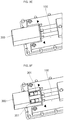
FIG. 2 is a flowchart illustrating a method for manufacturing a lower housing of a battery pack according to the present invention.FIGS. 3A to 3G are views illustrating the method for manufacturing a lower housing of a battery pack according to the present invention. - Referring to
FIG. 2 , the method for manufacturing a lower housing of a battery pack according to the present invention includes the steps of preparing a cooling pipe (S01), preparing a slider (S02), inserting a quick connector insertion part into the slider (S03), coupling a lower housing mold (S04), forming the lower housing by using a lower housing mold (S05), and removing the slider and the lower housing mold (S06). - Referring to
FIG. 3A , in the step of preparing a cooling pipe (S01), thecooling pipe 200 embedded in thelower housing 100 of the battery pack for cooling the battery pack is prepared. Thecooling pipe 200 includes the quickconnector insertion part 201, which protrudes to the outside of thelower housing 100 so as to be insert-connected to an external quick connector (not shown). Most regions of the quickconnector insertion part 201 have a first outer diameter. The first outer diameter corresponds to an inner diameter of the quickconnector insertion part 201. Meanwhile, the quickconnector insertion part 201 includes a lockingprotrusion 202 having a second outer diameter for enabling the lockingprotrusion 202 to be fixed to the quick connector in the inward direction in a first length l1 at its end, and ajoint part 203 having a predetermined length and a third outer diameter corresponding to the second outer diameter in the inward direction in a second length l2 at the end of the quickconnector insertion part 201. The second length l2 is greater than the first length l1. Thejoint part 203 is aregion cooling pipe 200 is installed to be embedded in thelower housing 100. - In the step of preparing a slider (S02), the
slider 300 is prepared. The quickconnector insertion part 201 of thecooling pipe 200 has a diameter corresponding to the third outer diameter of thejoint part 203, and a length corresponding to a length of thecooling pipe 200 protruding from thelower housing 100. In addition, theslider 300 may include two or morepipe insertion parts 301 so as to correspond to the number of coolingpipes 200 protruding from thelower housing 100. That is to say, since two coolingpipes 200, consisting of a cooling water inlet pipe and a cooling water outlet pipe, are generally exposed from thelower housing 100 to be connected to the quick connector, twopipe insertion parts 301 are preferably installed in theslider 300, like the two coolingpipes 200. In addition, distances between each of the two or morepipe insertion parts 301 may correspond to distances between the quickconnector insertion parts 201 of the coolingpipes 200, which are exposed from thelower housing 100 to then be spaced apart from each other. - In the step of inserting the quick connector insertion part into the pipe insertion part of the slider (S03), as shown in
FIGS. 3B and 3C , the quickconnector insertion part 201 of thecooling pipe 200 is inserted into thepipe insertion part 301 of theslider 300. Here, as shown inFIG. 3C , since the quickconnector insertion part 201 has an inner diameter large enough to accommodate the third outer diameter of thejoint part 203 and the second outer diameter of the lockingprotrusion 202, theslider 300 is able to accommodate even a region of thejoint part 203 without being locked on the lockingprotrusion 202. Here, the second outer diameter of the lockingprotrusion 202 is smaller than or equal to the third outer diameter of thejoint part 203. - In the coupling of the lower housing mold (S04), as shown in
FIG. 3D , thelower housing mold 400 is coupled to thecooling pipe 200. Thelower housing mold 400 may also be coupled to theslider 300. - In the step of forming the lower housing (S05), a casting is poured to the lower housing mold to fabricate a mold of the
lower housing 100. Thelower housing 100 may be made from a metallic material, such as aluminum, or a plastic material. - In the step of removing the slider and the lower housing mold (S06), as shown in
FIG. 3E , thelower housing mold 400 is removed, leaving only theslider 300 coupled to thecooling pipe 200 in the formedlower housing 100. That is to say, theslider 300 may be extracted from the quickconnector insertion part 201 of thecooling pipe 200 without being affected by the lower housing molding process. -
FIG. 3F shows a cutaway view illustrating an upper region of a section of theslide 300, into which thecooling pipe 200 is inserted. Referring toFIG. 3F , some regions of the lockingprotrusion 202 and thejoint part 203 of the quickconnector insertion part 201 are inserted into thepipe insertion part 301 of theslide 300, and it is confirmed that molding of thelower housing 100 is not affected by the quickconnector insertion part 201. In addition, the outer diameter of the lockingprotrusion 202 of the quickconnector insertion part 201 is smaller than the inner diameter of thepipe insertion part 301, theslider 300 may not be locked on the lockingprotrusion 202, thereby obviating a possible problem associated with slider extraction in the step of removing theslider 300. Accordingly, as shown inFIG. 3G , if theslider 300 is extracted and removed from the quickconnector insertion part 201, the quickconnector insertion part 201 of thecooling pipe 200, which protrudes to the outside of thelower housing 100, is finally disposed over a cooling pipe inlet of thelower housing 100. In addition, the lockingprotrusion 202 to be coupled to a quick connector (not shown) may exist in a mid portion of the quickconnector insertion part 201. - As described above, in the method for manufacturing the lower housing of the battery pack according to an embodiment of the present invention, a region of the quick connector insertion part of the cooling pipe has an outer diameter larger than or equal to that of the locking protrusion (i.e., the joint part of the cooling pipe), and the quick connector insertion part is extracted through the slider to fabricate a mold of the lower housing, followed by removing the slider, thereby solving the problem associated with the slide extraction due to an undercut shape of the locking protrusion.
- Although the foregoing embodiment has been described to practice the lower housing of a battery pack of the present invention, the embodiment is set forth for illustrative purposes and do not serve to limit the invention. Those skilled in the art will readily appreciate that many modifications and variations can be made, without departing from the spirit and scope of the invention as defined in the appended claims, and such modifications and variations are encompassed within the scope and spirit of the present invention.
Explanation of reference numerals 100: Lower housing 101, 200: Cooling pipe 103, 202: Locking protrusion 203: Joint part 300: Slider 301: Pipe insertion part 400: Lower housing mold
Claims (6)
- A method for manufacturing a lower housing of a battery pack, the method comprising the steps of:preparing a cooling pipe, which protrudes to the outside of the lower housing so as to be insert-connected to an external quick connector, includes a locking protrusion having a first outer diameter at a quick connector insertion part to be connected to the quick connector, and a second outer diameter for enabling the protrusion to be fixed to the quick connector in the inward direction in a first length at the end of the quick connector insertion part, and has a joint part which has a predetermined length and a third outer diameter corresponding to the second outer diameter in the inward direction in a second length longer than the first length at the end of the quick connector insertion part, and which is to be disposed over a cooling pipe inlet of the lower housing;preparing a slider including one or more pipe insertion parts having inner diameters corresponding to the third outer diameter of the joint part;inserting the quick connector insertion parts of the cooling pipe into the pipe insertion parts of the slider;coupling a lower housing mold to the cooling pipe;forming the lower housing by using the lower housing mold; andremoving the slider and the lower housing mold.
- The method of claim 1, wherein the second outer diameter is greater than the first outer diameter, and the third outer diameter is greater than the second outer diameter.
- The method of claim 1, wherein the second outer diameter is greater than the first outer diameter, and the third outer diameter is equal to the second outer diameter.
- The method of claim 1, wherein a length of the slider insertion part corresponds to a length of the cooling pipe protruding from the lower housing.
- The method of claim 1, wherein a distance between one or more pipe insertion parts of the slide corresponds to a distance between quick connector insertion parts of the cooling pipe protruding to the outside of the lower housing.
- The method of claim 1, wherein the step of forming the lower housing is performed by using a molding process.
Applications Claiming Priority (2)
| Application Number | Priority Date | Filing Date | Title |
|---|---|---|---|
| KR1020170045511A KR102288545B1 (en) | 2017-04-07 | 2017-04-07 | Method for manufacturing of Battery Pack Low Housing |
| PCT/KR2018/000985 WO2018186570A1 (en) | 2017-04-07 | 2018-01-23 | Method for manufacturing lower housing of battery pack |
Publications (3)
| Publication Number | Publication Date |
|---|---|
| EP3608989A1 true EP3608989A1 (en) | 2020-02-12 |
| EP3608989A4 EP3608989A4 (en) | 2021-01-13 |
| EP3608989B1 EP3608989B1 (en) | 2024-07-03 |
Family
ID=63713295
Family Applications (1)
| Application Number | Title | Priority Date | Filing Date |
|---|---|---|---|
| EP18780295.4A Active EP3608989B1 (en) | 2017-04-07 | 2018-01-23 | Method for manufacturing lower housing of battery pack |
Country Status (7)
| Country | Link |
|---|---|
| US (1) | US11431043B2 (en) |
| EP (1) | EP3608989B1 (en) |
| KR (1) | KR102288545B1 (en) |
| CN (1) | CN110419122B (en) |
| HU (1) | HUE068537T2 (en) |
| PL (1) | PL3608989T3 (en) |
| WO (1) | WO2018186570A1 (en) |
Cited By (1)
| Publication number | Priority date | Publication date | Assignee | Title |
|---|---|---|---|---|
| CN113300035A (en) * | 2021-04-29 | 2021-08-24 | 苏州财易电子科技有限公司 | Energy storage battery cluster with heat dissipation and fire control function |
Family Cites Families (16)
| Publication number | Priority date | Publication date | Assignee | Title |
|---|---|---|---|---|
| JP2007001062A (en) | 2005-06-22 | 2007-01-11 | Seiko Epson Corp | Cooling plate |
| JP4881753B2 (en) | 2006-03-29 | 2012-02-22 | 東海ゴム工業株式会社 | Quick connector |
| PT2716428T (en) * | 2011-06-01 | 2016-11-04 | Comercial De Utiles Y Moldes Sa | Compact slide rail for injection molds |
| KR101446956B1 (en) * | 2012-12-13 | 2014-11-04 | 대한칼소닉주식회사 | Battery heat sink having structure stacked fluid path |
| KR101357472B1 (en) | 2012-12-24 | 2014-02-03 | 쌍용자동차 주식회사 | Intercooler and plastic duct combination structure for automobile |
| KR101930010B1 (en) | 2012-12-26 | 2018-12-18 | 한온시스템 주식회사 | Cooling module |
| SG11201506334UA (en) * | 2013-02-18 | 2015-09-29 | Heng Man Hoong | Angled-mold core actuating mechanism |
| JP6064730B2 (en) | 2013-03-26 | 2017-01-25 | 三菱自動車工業株式会社 | Cooling system |
| FR3003938A1 (en) * | 2013-03-29 | 2014-10-03 | Valeo Systemes Thermiques | THERMAL EXCHANGE PLATE FOR THERMAL BATTERY MANAGEMENT AND METHOD OF MANUFACTURING THE SAME. |
| US9059542B2 (en) * | 2013-07-23 | 2015-06-16 | Tyco Electronics Corporation | Quick connect power connector |
| KR101623251B1 (en) | 2014-05-09 | 2016-05-20 | 에스케이이노베이션 주식회사 | Cooling system for battery module |
| JP2016031798A (en) * | 2014-07-28 | 2016-03-07 | カルソニックカンセイ株式会社 | Heat exchanger |
| DE102014217931A1 (en) | 2014-09-08 | 2016-03-10 | Bayerische Motoren Werke Aktiengesellschaft | High-voltage battery cooling device |
| CN104266389A (en) * | 2014-10-20 | 2015-01-07 | 无锡环特太阳能科技有限公司 | Pressure-bearing storage water tank with built-in large diameter heat exchange tube with fins |
| KR102314041B1 (en) * | 2015-03-12 | 2021-10-18 | 삼성에스디아이 주식회사 | Battery pack |
| CN106329030B (en) * | 2015-06-30 | 2021-06-18 | 比亚迪股份有限公司 | a cooling plate |
-
2017
- 2017-04-07 KR KR1020170045511A patent/KR102288545B1/en active Active
-
2018
- 2018-01-23 WO PCT/KR2018/000985 patent/WO2018186570A1/en not_active Ceased
- 2018-01-23 CN CN201880017763.3A patent/CN110419122B/en active Active
- 2018-01-23 HU HUE18780295A patent/HUE068537T2/en unknown
- 2018-01-23 US US16/491,003 patent/US11431043B2/en active Active
- 2018-01-23 PL PL18780295.4T patent/PL3608989T3/en unknown
- 2018-01-23 EP EP18780295.4A patent/EP3608989B1/en active Active
Cited By (2)
| Publication number | Priority date | Publication date | Assignee | Title |
|---|---|---|---|---|
| CN113300035A (en) * | 2021-04-29 | 2021-08-24 | 苏州财易电子科技有限公司 | Energy storage battery cluster with heat dissipation and fire control function |
| CN113300035B (en) * | 2021-04-29 | 2023-03-17 | 苏州财易电子科技有限公司 | Energy storage battery cluster with heat dissipation and fire control function |
Also Published As
| Publication number | Publication date |
|---|---|
| EP3608989A4 (en) | 2021-01-13 |
| EP3608989B1 (en) | 2024-07-03 |
| CN110419122A (en) | 2019-11-05 |
| CN110419122B (en) | 2022-05-31 |
| KR102288545B1 (en) | 2021-08-11 |
| KR20180113854A (en) | 2018-10-17 |
| HUE068537T2 (en) | 2025-01-28 |
| WO2018186570A1 (en) | 2018-10-11 |
| PL3608989T3 (en) | 2024-09-09 |
| US11431043B2 (en) | 2022-08-30 |
| US20200020997A1 (en) | 2020-01-16 |
Similar Documents
| Publication | Publication Date | Title |
|---|---|---|
| US11652246B2 (en) | Battery module and method of manufacturing the same | |
| EP3151306B1 (en) | Rechargeable battery | |
| US8679667B2 (en) | One piece compression resistant prismatic cell | |
| US8378214B2 (en) | Harness connection member | |
| KR101736378B1 (en) | Frame for secondary battery and battery module including the same | |
| US8664528B2 (en) | Wire harness and method for making the same | |
| EP2790243B1 (en) | Battery unit and battery module using the same | |
| US8987958B2 (en) | Waterproof motor stator structure | |
| CN115320007B (en) | Injection molding pole post forming method and power battery top cover structure | |
| CN106099468A (en) | Connector and its manufacturing method | |
| US20080226978A1 (en) | Support foot for battery pack, battery pack with the same and method of manufacturing the same | |
| EP3608989B1 (en) | Method for manufacturing lower housing of battery pack | |
| KR101725901B1 (en) | Battery Cell Comprising Battery Case of Shape Corresponding to Electrode Assembly of Stair-like Structure | |
| US8637172B2 (en) | Secondary battery | |
| US8734969B2 (en) | Dummy cell for battery pack and molding apparatus for manufacturing battery pack | |
| US20230015382A1 (en) | Insert molding method and insert molding component | |
| KR102676148B1 (en) | Bus bar protection assembly, method of assembling the same, and battery pack including the same | |
| CN115088116B (en) | Coolant port assembly | |
| US20250226509A1 (en) | Battery module | |
| KR101872307B1 (en) | Method for Preparing Battery Pack Using Fixing Structure for Hot Melting and Battery Pack Prepared by Using the Same | |
| KR101742303B1 (en) | Method for Battery Cell | |
| US9088013B2 (en) | Case for battery comprising bent edge and seal, and secondary battery including the case | |
| CN115663412B (en) | Terminal subassembly, top cap subassembly, energy memory and consumer | |
| CN116581491A (en) | Cell terminal assembly and top cover assembly thereof | |
| CN217123835U (en) | A mould for moulding plastics electrified cable part |
Legal Events
| Date | Code | Title | Description |
|---|---|---|---|
| STAA | Information on the status of an ep patent application or granted ep patent |
Free format text: STATUS: THE INTERNATIONAL PUBLICATION HAS BEEN MADE |
|
| PUAI | Public reference made under article 153(3) epc to a published international application that has entered the european phase |
Free format text: ORIGINAL CODE: 0009012 |
|
| STAA | Information on the status of an ep patent application or granted ep patent |
Free format text: STATUS: REQUEST FOR EXAMINATION WAS MADE |
|
| 17P | Request for examination filed |
Effective date: 20190813 |
|
| AK | Designated contracting states |
Kind code of ref document: A1 Designated state(s): AL AT BE BG CH CY CZ DE DK EE ES FI FR GB GR HR HU IE IS IT LI LT LU LV MC MK MT NL NO PL PT RO RS SE SI SK SM TR |
|
| AX | Request for extension of the european patent |
Extension state: BA ME |
|
| DAV | Request for validation of the european patent (deleted) | ||
| DAX | Request for extension of the european patent (deleted) | ||
| A4 | Supplementary search report drawn up and despatched |
Effective date: 20201215 |
|
| RIC1 | Information provided on ipc code assigned before grant |
Ipc: B29C 45/00 20060101ALI20201209BHEP Ipc: B29D 99/00 20100101ALI20201209BHEP Ipc: H01M 10/613 20140101ALI20201209BHEP Ipc: H01M 2/10 20060101AFI20201209BHEP Ipc: H01M 10/6556 20140101ALI20201209BHEP Ipc: B29C 33/38 20060101ALI20201209BHEP Ipc: H01M 10/6567 20140101ALI20201209BHEP |
|
| REG | Reference to a national code |
Ref country code: DE Ref legal event code: R079 Free format text: PREVIOUS MAIN CLASS: H01M0002100000 Ipc: H01M0010655600 Ref country code: DE Ref legal event code: R079 Ref document number: 602018071324 Country of ref document: DE Free format text: PREVIOUS MAIN CLASS: H01M0002100000 Ipc: H01M0010655600 |
|
| GRAP | Despatch of communication of intention to grant a patent |
Free format text: ORIGINAL CODE: EPIDOSNIGR1 |
|
| STAA | Information on the status of an ep patent application or granted ep patent |
Free format text: STATUS: GRANT OF PATENT IS INTENDED |
|
| RIC1 | Information provided on ipc code assigned before grant |
Ipc: B29L 31/00 20060101ALI20240123BHEP Ipc: B29C 45/14 20060101ALI20240123BHEP Ipc: B29D 99/00 20100101ALI20240123BHEP Ipc: B29C 45/33 20060101ALI20240123BHEP Ipc: H01M 10/6567 20140101ALI20240123BHEP Ipc: H01M 10/613 20140101ALI20240123BHEP Ipc: H01M 10/6556 20140101AFI20240123BHEP |
|
| INTG | Intention to grant announced |
Effective date: 20240207 |
|
| GRAS | Grant fee paid |
Free format text: ORIGINAL CODE: EPIDOSNIGR3 |
|
| GRAA | (expected) grant |
Free format text: ORIGINAL CODE: 0009210 |
|
| STAA | Information on the status of an ep patent application or granted ep patent |
Free format text: STATUS: THE PATENT HAS BEEN GRANTED |
|
| AK | Designated contracting states |
Kind code of ref document: B1 Designated state(s): AL AT BE BG CH CY CZ DE DK EE ES FI FR GB GR HR HU IE IS IT LI LT LU LV MC MK MT NL NO PL PT RO RS SE SI SK SM TR |
|
| REG | Reference to a national code |
Ref country code: CH Ref legal event code: EP |
|
| REG | Reference to a national code |
Ref country code: DE Ref legal event code: R096 Ref document number: 602018071324 Country of ref document: DE |
|
| REG | Reference to a national code |
Ref country code: SE Ref legal event code: TRGR |
|
| REG | Reference to a national code |
Ref country code: LT Ref legal event code: MG9D |
|
| REG | Reference to a national code |
Ref country code: NL Ref legal event code: MP Effective date: 20240703 |
|
| PG25 | Lapsed in a contracting state [announced via postgrant information from national office to epo] |
Ref country code: PT Free format text: LAPSE BECAUSE OF FAILURE TO SUBMIT A TRANSLATION OF THE DESCRIPTION OR TO PAY THE FEE WITHIN THE PRESCRIBED TIME-LIMIT Effective date: 20241104 |
|
| PG25 | Lapsed in a contracting state [announced via postgrant information from national office to epo] |
Ref country code: NL Free format text: LAPSE BECAUSE OF FAILURE TO SUBMIT A TRANSLATION OF THE DESCRIPTION OR TO PAY THE FEE WITHIN THE PRESCRIBED TIME-LIMIT Effective date: 20240703 |
|
| PG25 | Lapsed in a contracting state [announced via postgrant information from national office to epo] |
Ref country code: PT Free format text: LAPSE BECAUSE OF FAILURE TO SUBMIT A TRANSLATION OF THE DESCRIPTION OR TO PAY THE FEE WITHIN THE PRESCRIBED TIME-LIMIT Effective date: 20241104 Ref country code: NL Free format text: LAPSE BECAUSE OF FAILURE TO SUBMIT A TRANSLATION OF THE DESCRIPTION OR TO PAY THE FEE WITHIN THE PRESCRIBED TIME-LIMIT Effective date: 20240703 |
|
| PG25 | Lapsed in a contracting state [announced via postgrant information from national office to epo] |
Ref country code: NO Free format text: LAPSE BECAUSE OF FAILURE TO SUBMIT A TRANSLATION OF THE DESCRIPTION OR TO PAY THE FEE WITHIN THE PRESCRIBED TIME-LIMIT Effective date: 20241003 |
|
| PG25 | Lapsed in a contracting state [announced via postgrant information from national office to epo] |
Ref country code: GR Free format text: LAPSE BECAUSE OF FAILURE TO SUBMIT A TRANSLATION OF THE DESCRIPTION OR TO PAY THE FEE WITHIN THE PRESCRIBED TIME-LIMIT Effective date: 20241004 Ref country code: FI Free format text: LAPSE BECAUSE OF FAILURE TO SUBMIT A TRANSLATION OF THE DESCRIPTION OR TO PAY THE FEE WITHIN THE PRESCRIBED TIME-LIMIT Effective date: 20240703 |
|
| PG25 | Lapsed in a contracting state [announced via postgrant information from national office to epo] |
Ref country code: BG Free format text: LAPSE BECAUSE OF FAILURE TO SUBMIT A TRANSLATION OF THE DESCRIPTION OR TO PAY THE FEE WITHIN THE PRESCRIBED TIME-LIMIT Effective date: 20240703 |
|
| PG25 | Lapsed in a contracting state [announced via postgrant information from national office to epo] |
Ref country code: LV Free format text: LAPSE BECAUSE OF FAILURE TO SUBMIT A TRANSLATION OF THE DESCRIPTION OR TO PAY THE FEE WITHIN THE PRESCRIBED TIME-LIMIT Effective date: 20240703 |
|
| PG25 | Lapsed in a contracting state [announced via postgrant information from national office to epo] |
Ref country code: IS Free format text: LAPSE BECAUSE OF FAILURE TO SUBMIT A TRANSLATION OF THE DESCRIPTION OR TO PAY THE FEE WITHIN THE PRESCRIBED TIME-LIMIT Effective date: 20241103 |
|
| PG25 | Lapsed in a contracting state [announced via postgrant information from national office to epo] |
Ref country code: CZ Free format text: LAPSE BECAUSE OF FAILURE TO SUBMIT A TRANSLATION OF THE DESCRIPTION OR TO PAY THE FEE WITHIN THE PRESCRIBED TIME-LIMIT Effective date: 20240703 Ref country code: HR Free format text: LAPSE BECAUSE OF FAILURE TO SUBMIT A TRANSLATION OF THE DESCRIPTION OR TO PAY THE FEE WITHIN THE PRESCRIBED TIME-LIMIT Effective date: 20240703 |
|
| PG25 | Lapsed in a contracting state [announced via postgrant information from national office to epo] |
Ref country code: ES Free format text: LAPSE BECAUSE OF FAILURE TO SUBMIT A TRANSLATION OF THE DESCRIPTION OR TO PAY THE FEE WITHIN THE PRESCRIBED TIME-LIMIT Effective date: 20240703 Ref country code: RS Free format text: LAPSE BECAUSE OF FAILURE TO SUBMIT A TRANSLATION OF THE DESCRIPTION OR TO PAY THE FEE WITHIN THE PRESCRIBED TIME-LIMIT Effective date: 20241003 |
|
| REG | Reference to a national code |
Ref country code: HU Ref legal event code: AG4A Ref document number: E068537 Country of ref document: HU |
|
| PG25 | Lapsed in a contracting state [announced via postgrant information from national office to epo] |
Ref country code: RS Free format text: LAPSE BECAUSE OF FAILURE TO SUBMIT A TRANSLATION OF THE DESCRIPTION OR TO PAY THE FEE WITHIN THE PRESCRIBED TIME-LIMIT Effective date: 20241003 Ref country code: NO Free format text: LAPSE BECAUSE OF FAILURE TO SUBMIT A TRANSLATION OF THE DESCRIPTION OR TO PAY THE FEE WITHIN THE PRESCRIBED TIME-LIMIT Effective date: 20241003 Ref country code: LV Free format text: LAPSE BECAUSE OF FAILURE TO SUBMIT A TRANSLATION OF THE DESCRIPTION OR TO PAY THE FEE WITHIN THE PRESCRIBED TIME-LIMIT Effective date: 20240703 Ref country code: IS Free format text: LAPSE BECAUSE OF FAILURE TO SUBMIT A TRANSLATION OF THE DESCRIPTION OR TO PAY THE FEE WITHIN THE PRESCRIBED TIME-LIMIT Effective date: 20241103 Ref country code: HR Free format text: LAPSE BECAUSE OF FAILURE TO SUBMIT A TRANSLATION OF THE DESCRIPTION OR TO PAY THE FEE WITHIN THE PRESCRIBED TIME-LIMIT Effective date: 20240703 Ref country code: GR Free format text: LAPSE BECAUSE OF FAILURE TO SUBMIT A TRANSLATION OF THE DESCRIPTION OR TO PAY THE FEE WITHIN THE PRESCRIBED TIME-LIMIT Effective date: 20241004 Ref country code: FI Free format text: LAPSE BECAUSE OF FAILURE TO SUBMIT A TRANSLATION OF THE DESCRIPTION OR TO PAY THE FEE WITHIN THE PRESCRIBED TIME-LIMIT Effective date: 20240703 Ref country code: ES Free format text: LAPSE BECAUSE OF FAILURE TO SUBMIT A TRANSLATION OF THE DESCRIPTION OR TO PAY THE FEE WITHIN THE PRESCRIBED TIME-LIMIT Effective date: 20240703 Ref country code: CZ Free format text: LAPSE BECAUSE OF FAILURE TO SUBMIT A TRANSLATION OF THE DESCRIPTION OR TO PAY THE FEE WITHIN THE PRESCRIBED TIME-LIMIT Effective date: 20240703 Ref country code: BG Free format text: LAPSE BECAUSE OF FAILURE TO SUBMIT A TRANSLATION OF THE DESCRIPTION OR TO PAY THE FEE WITHIN THE PRESCRIBED TIME-LIMIT Effective date: 20240703 |
|
| REG | Reference to a national code |
Ref country code: DE Ref legal event code: R097 Ref document number: 602018071324 Country of ref document: DE |
|
| PG25 | Lapsed in a contracting state [announced via postgrant information from national office to epo] |
Ref country code: DK Free format text: LAPSE BECAUSE OF FAILURE TO SUBMIT A TRANSLATION OF THE DESCRIPTION OR TO PAY THE FEE WITHIN THE PRESCRIBED TIME-LIMIT Effective date: 20240703 Ref country code: RO Free format text: LAPSE BECAUSE OF FAILURE TO SUBMIT A TRANSLATION OF THE DESCRIPTION OR TO PAY THE FEE WITHIN THE PRESCRIBED TIME-LIMIT Effective date: 20240703 Ref country code: SM Free format text: LAPSE BECAUSE OF FAILURE TO SUBMIT A TRANSLATION OF THE DESCRIPTION OR TO PAY THE FEE WITHIN THE PRESCRIBED TIME-LIMIT Effective date: 20240703 |
|
| PG25 | Lapsed in a contracting state [announced via postgrant information from national office to epo] |
Ref country code: EE Free format text: LAPSE BECAUSE OF FAILURE TO SUBMIT A TRANSLATION OF THE DESCRIPTION OR TO PAY THE FEE WITHIN THE PRESCRIBED TIME-LIMIT Effective date: 20240703 |
|
| PG25 | Lapsed in a contracting state [announced via postgrant information from national office to epo] |
Ref country code: SK Free format text: LAPSE BECAUSE OF FAILURE TO SUBMIT A TRANSLATION OF THE DESCRIPTION OR TO PAY THE FEE WITHIN THE PRESCRIBED TIME-LIMIT Effective date: 20240703 Ref country code: IT Free format text: LAPSE BECAUSE OF FAILURE TO SUBMIT A TRANSLATION OF THE DESCRIPTION OR TO PAY THE FEE WITHIN THE PRESCRIBED TIME-LIMIT Effective date: 20240703 |
|
| PLBE | No opposition filed within time limit |
Free format text: ORIGINAL CODE: 0009261 |
|
| STAA | Information on the status of an ep patent application or granted ep patent |
Free format text: STATUS: NO OPPOSITION FILED WITHIN TIME LIMIT |
|
| 26N | No opposition filed |
Effective date: 20250404 |
|
| REG | Reference to a national code |
Ref country code: CH Ref legal event code: PL |
|
| PG25 | Lapsed in a contracting state [announced via postgrant information from national office to epo] |
Ref country code: MC Free format text: LAPSE BECAUSE OF FAILURE TO SUBMIT A TRANSLATION OF THE DESCRIPTION OR TO PAY THE FEE WITHIN THE PRESCRIBED TIME-LIMIT Effective date: 20240703 Ref country code: LU Free format text: LAPSE BECAUSE OF NON-PAYMENT OF DUE FEES Effective date: 20250123 |
|
| REG | Reference to a national code |
Ref country code: AT Ref legal event code: UEP Ref document number: 1700790 Country of ref document: AT Kind code of ref document: T Effective date: 20240703 |
|
| PG25 | Lapsed in a contracting state [announced via postgrant information from national office to epo] |
Ref country code: BE Free format text: LAPSE BECAUSE OF NON-PAYMENT OF DUE FEES Effective date: 20250131 |
|
| PG25 | Lapsed in a contracting state [announced via postgrant information from national office to epo] |
Ref country code: CH Free format text: LAPSE BECAUSE OF NON-PAYMENT OF DUE FEES Effective date: 20250131 |
|
| REG | Reference to a national code |
Ref country code: BE Ref legal event code: MM Effective date: 20250131 |
|
| PGFP | Annual fee paid to national office [announced via postgrant information from national office to epo] |
Ref country code: FR Payment date: 20251231 Year of fee payment: 9 |
|
| PG25 | Lapsed in a contracting state [announced via postgrant information from national office to epo] |
Ref country code: IE Free format text: LAPSE BECAUSE OF NON-PAYMENT OF DUE FEES Effective date: 20250123 |
|
| PGFP | Annual fee paid to national office [announced via postgrant information from national office to epo] |
Ref country code: HU Payment date: 20260130 Year of fee payment: 9 |
|
| PGFP | Annual fee paid to national office [announced via postgrant information from national office to epo] |
Ref country code: SE Payment date: 20251230 Year of fee payment: 9 |
|
| PGFP | Annual fee paid to national office [announced via postgrant information from national office to epo] |
Ref country code: GB Payment date: 20260106 Year of fee payment: 9 |
|
| PGFP | Annual fee paid to national office [announced via postgrant information from national office to epo] |
Ref country code: DE Payment date: 20251230 Year of fee payment: 9 |
|
| PGFP | Annual fee paid to national office [announced via postgrant information from national office to epo] |
Ref country code: AT Payment date: 20251230 Year of fee payment: 9 |
|
| PGFP | Annual fee paid to national office [announced via postgrant information from national office to epo] |
Ref country code: PL Payment date: 20260107 Year of fee payment: 9 |