EP3608707A1 - Dimmable display system - Google Patents
Dimmable display system Download PDFInfo
- Publication number
- EP3608707A1 EP3608707A1 EP19190705.4A EP19190705A EP3608707A1 EP 3608707 A1 EP3608707 A1 EP 3608707A1 EP 19190705 A EP19190705 A EP 19190705A EP 3608707 A1 EP3608707 A1 EP 3608707A1
- Authority
- EP
- European Patent Office
- Prior art keywords
- lens
- dimmable
- display
- light
- transmission
- Prior art date
- Legal status (The legal status is an assumption and is not a legal conclusion. Google has not performed a legal analysis and makes no representation as to the accuracy of the status listed.)
- Granted
Links
Images





Classifications
-
- G—PHYSICS
- G02—OPTICS
- G02F—OPTICAL DEVICES OR ARRANGEMENTS FOR THE CONTROL OF LIGHT BY MODIFICATION OF THE OPTICAL PROPERTIES OF THE MEDIA OF THE ELEMENTS INVOLVED THEREIN; NON-LINEAR OPTICS; FREQUENCY-CHANGING OF LIGHT; OPTICAL LOGIC ELEMENTS; OPTICAL ANALOGUE/DIGITAL CONVERTERS
- G02F1/00—Devices or arrangements for the control of the intensity, colour, phase, polarisation or direction of light arriving from an independent light source, e.g. switching, gating or modulating; Non-linear optics
- G02F1/01—Devices or arrangements for the control of the intensity, colour, phase, polarisation or direction of light arriving from an independent light source, e.g. switching, gating or modulating; Non-linear optics for the control of the intensity, phase, polarisation or colour
- G02F1/13—Devices or arrangements for the control of the intensity, colour, phase, polarisation or direction of light arriving from an independent light source, e.g. switching, gating or modulating; Non-linear optics for the control of the intensity, phase, polarisation or colour based on liquid crystals, e.g. single liquid crystal display cells
- G02F1/133—Constructional arrangements; Operation of liquid crystal cells; Circuit arrangements
- G02F1/13306—Circuit arrangements or driving methods for the control of single liquid crystal cells
- G02F1/13318—Circuits comprising a photodetector
-
- G—PHYSICS
- G02—OPTICS
- G02B—OPTICAL ELEMENTS, SYSTEMS OR APPARATUS
- G02B27/00—Optical systems or apparatus not provided for by any of the groups G02B1/00 - G02B26/00, G02B30/00
- G02B27/01—Head-up displays
- G02B27/0101—Head-up displays characterised by optical features
-
- G—PHYSICS
- G02—OPTICS
- G02F—OPTICAL DEVICES OR ARRANGEMENTS FOR THE CONTROL OF LIGHT BY MODIFICATION OF THE OPTICAL PROPERTIES OF THE MEDIA OF THE ELEMENTS INVOLVED THEREIN; NON-LINEAR OPTICS; FREQUENCY-CHANGING OF LIGHT; OPTICAL LOGIC ELEMENTS; OPTICAL ANALOGUE/DIGITAL CONVERTERS
- G02F1/00—Devices or arrangements for the control of the intensity, colour, phase, polarisation or direction of light arriving from an independent light source, e.g. switching, gating or modulating; Non-linear optics
- G02F1/01—Devices or arrangements for the control of the intensity, colour, phase, polarisation or direction of light arriving from an independent light source, e.g. switching, gating or modulating; Non-linear optics for the control of the intensity, phase, polarisation or colour
- G02F1/13—Devices or arrangements for the control of the intensity, colour, phase, polarisation or direction of light arriving from an independent light source, e.g. switching, gating or modulating; Non-linear optics for the control of the intensity, phase, polarisation or colour based on liquid crystals, e.g. single liquid crystal display cells
- G02F1/133—Constructional arrangements; Operation of liquid crystal cells; Circuit arrangements
- G02F1/13306—Circuit arrangements or driving methods for the control of single liquid crystal cells
-
- G—PHYSICS
- G09—EDUCATION; CRYPTOGRAPHY; DISPLAY; ADVERTISING; SEALS
- G09G—ARRANGEMENTS OR CIRCUITS FOR CONTROL OF INDICATING DEVICES USING STATIC MEANS TO PRESENT VARIABLE INFORMATION
- G09G5/00—Control arrangements or circuits for visual indicators common to cathode-ray tube indicators and other visual indicators
- G09G5/10—Intensity circuits
-
- G—PHYSICS
- G02—OPTICS
- G02F—OPTICAL DEVICES OR ARRANGEMENTS FOR THE CONTROL OF LIGHT BY MODIFICATION OF THE OPTICAL PROPERTIES OF THE MEDIA OF THE ELEMENTS INVOLVED THEREIN; NON-LINEAR OPTICS; FREQUENCY-CHANGING OF LIGHT; OPTICAL LOGIC ELEMENTS; OPTICAL ANALOGUE/DIGITAL CONVERTERS
- G02F1/00—Devices or arrangements for the control of the intensity, colour, phase, polarisation or direction of light arriving from an independent light source, e.g. switching, gating or modulating; Non-linear optics
- G02F1/01—Devices or arrangements for the control of the intensity, colour, phase, polarisation or direction of light arriving from an independent light source, e.g. switching, gating or modulating; Non-linear optics for the control of the intensity, phase, polarisation or colour
- G02F1/13—Devices or arrangements for the control of the intensity, colour, phase, polarisation or direction of light arriving from an independent light source, e.g. switching, gating or modulating; Non-linear optics for the control of the intensity, phase, polarisation or colour based on liquid crystals, e.g. single liquid crystal display cells
- G02F1/133—Constructional arrangements; Operation of liquid crystal cells; Circuit arrangements
- G02F1/1333—Constructional arrangements; Manufacturing methods
- G02F1/133388—Constructional arrangements; Manufacturing methods with constructional differences between the display region and the peripheral region
-
- G—PHYSICS
- G02—OPTICS
- G02F—OPTICAL DEVICES OR ARRANGEMENTS FOR THE CONTROL OF LIGHT BY MODIFICATION OF THE OPTICAL PROPERTIES OF THE MEDIA OF THE ELEMENTS INVOLVED THEREIN; NON-LINEAR OPTICS; FREQUENCY-CHANGING OF LIGHT; OPTICAL LOGIC ELEMENTS; OPTICAL ANALOGUE/DIGITAL CONVERTERS
- G02F1/00—Devices or arrangements for the control of the intensity, colour, phase, polarisation or direction of light arriving from an independent light source, e.g. switching, gating or modulating; Non-linear optics
- G02F1/01—Devices or arrangements for the control of the intensity, colour, phase, polarisation or direction of light arriving from an independent light source, e.g. switching, gating or modulating; Non-linear optics for the control of the intensity, phase, polarisation or colour
- G02F1/15—Devices or arrangements for the control of the intensity, colour, phase, polarisation or direction of light arriving from an independent light source, e.g. switching, gating or modulating; Non-linear optics for the control of the intensity, phase, polarisation or colour based on an electrochromic effect
- G02F1/163—Operation of electrochromic cells, e.g. electrodeposition cells; Circuit arrangements therefor
-
- G—PHYSICS
- G02—OPTICS
- G02F—OPTICAL DEVICES OR ARRANGEMENTS FOR THE CONTROL OF LIGHT BY MODIFICATION OF THE OPTICAL PROPERTIES OF THE MEDIA OF THE ELEMENTS INVOLVED THEREIN; NON-LINEAR OPTICS; FREQUENCY-CHANGING OF LIGHT; OPTICAL LOGIC ELEMENTS; OPTICAL ANALOGUE/DIGITAL CONVERTERS
- G02F1/00—Devices or arrangements for the control of the intensity, colour, phase, polarisation or direction of light arriving from an independent light source, e.g. switching, gating or modulating; Non-linear optics
- G02F1/01—Devices or arrangements for the control of the intensity, colour, phase, polarisation or direction of light arriving from an independent light source, e.g. switching, gating or modulating; Non-linear optics for the control of the intensity, phase, polarisation or colour
- G02F1/17—Devices or arrangements for the control of the intensity, colour, phase, polarisation or direction of light arriving from an independent light source, e.g. switching, gating or modulating; Non-linear optics for the control of the intensity, phase, polarisation or colour based on variable-absorption elements not provided for in groups G02F1/015 - G02F1/169
- G02F1/172—Devices or arrangements for the control of the intensity, colour, phase, polarisation or direction of light arriving from an independent light source, e.g. switching, gating or modulating; Non-linear optics for the control of the intensity, phase, polarisation or colour based on variable-absorption elements not provided for in groups G02F1/015 - G02F1/169 based on a suspension of orientable dipolar particles, e.g. suspended particles displays
-
- G—PHYSICS
- G02—OPTICS
- G02F—OPTICAL DEVICES OR ARRANGEMENTS FOR THE CONTROL OF LIGHT BY MODIFICATION OF THE OPTICAL PROPERTIES OF THE MEDIA OF THE ELEMENTS INVOLVED THEREIN; NON-LINEAR OPTICS; FREQUENCY-CHANGING OF LIGHT; OPTICAL LOGIC ELEMENTS; OPTICAL ANALOGUE/DIGITAL CONVERTERS
- G02F2201/00—Constructional arrangements not provided for in groups G02F1/00 - G02F7/00
- G02F2201/44—Arrangements combining different electro-active layers, e.g. electrochromic, liquid crystal or electroluminescent layers
-
- G—PHYSICS
- G02—OPTICS
- G02F—OPTICAL DEVICES OR ARRANGEMENTS FOR THE CONTROL OF LIGHT BY MODIFICATION OF THE OPTICAL PROPERTIES OF THE MEDIA OF THE ELEMENTS INVOLVED THEREIN; NON-LINEAR OPTICS; FREQUENCY-CHANGING OF LIGHT; OPTICAL LOGIC ELEMENTS; OPTICAL ANALOGUE/DIGITAL CONVERTERS
- G02F2203/00—Function characteristic
- G02F2203/48—Variable attenuator
Definitions
- Automotive displays can be used to provide visual information throughout a vehicle. These displays can be located in an instrument panel to provide information about the vehicle that a driver or operator may want to be aware of, such as speed, fuel/energy remaining, etc. Additionally, displays can be located in other parts of the vehicle, such as the center console, seat backs for entertainment, and interior and exterior surfaces of the vehicle doors. However, these displays may not always include viewable information, particularly when the vehicle is in an off state (i.e., low or no power in the vehicle).
- a dimmable display lens system which includes a display element configured to emit light.
- a dimmable lens is disposed in the direction of light emission of the display element.
- the dimmable lens is configured to reduce the transmission of light emitted by the display through the dimmable lens.
- the dimmable lens includes a control system configured to reduce the transmission of light emitted by the display according to a plurality of light transmission reduction steps.
- the control system includes a control system configured to adjust the transmission of light through the dimmable lens based on at least a light sensor and a light source measuring light transmission through the dimmable lens.
- a dimmable display lens system comprising:
- the first light sensor is oriented towards the viewer.
- the ambient light then includes ambient light reflected or scattered from the viewer.
- the measure of ambient light provided by the first light sensor is then a measure of reflections from one or more surfaces of the dimmable lens (e.g. the external surface and/or internal surfaces) which the viewer may see superimposed on images provided by the display element.
- the dimmable display lens system is provided within a motor vehicle passenger compartment.
- the viewer may be a driver of the vehicle, in which case the display element may be part of a dashboard display.
- the viewer may be a passenger, in which case the display element may be part of an entertainment or information display system.
- the automatic dimming lens control system comprises a segment of the dimmable lens which overlaps an output area of the dimmable lens through which light from the display element is transmitted. A viewer views output from the display element through a main segment of the output area.
- the separate segment is preferably provided to one side of the main segment of the dimmable lens. The main segment and the separate segment may share a common layer which extends laterally across the extent of the dimmable lens.
- the ambient light will be ambient light within the motor vehicle passenger compartment, and the light detected by the forward looking light sensor will be predominantly or entirely external light directed into the passenger compartment. Particularly in the daytime, the intensity of such external light will be the main factor in the degree of dilation of the viewer's pupils.
- a method is provided of controlling a dimmable display lens disposed in the direction of light emission of a display element, the method comprising: setting the light emission of the display element to a constant value; generating a lookup table containing a plurality of light transmission incremental steps using a minimum transmission level of the dimmable display lens, a maximum transmission level of the dimmable display lens, and a predetermined number of light transmission incremental steps; selecting a light transmission incremental step from the lookup table; and adjusting the transmission of light emitted by the display element through the dimmable display lens according to the selected incremental step.
- the method may also include measuring ambient light to generate a transmission ratio lookup table and forward looking light to generate a luminance ratio table for transmission ratio table adaption control.
- the method may also include using a light source to project light through a segment of the dimmable display lens to a light sensor to measure the maximum transmission level via feedback control.
- the method may also include estimating the maximum transmission level or determining the maximum transmission level during startup of the dimmable display lens and the display element.
- Also described herein is a non-transient computer readable medium containing program instructions for causing a computer to perform the method of: setting the light emission of the display element to a constant value; generating a lookup table containing a plurality of light transmission incremental steps using a minimum transmission level of the dimmable display lens, a maximum transmission level of the dimmable display lens, a predetermined number of light transmission incremental steps and a selected light transmission incremental step; and adjusting the transmission of light emitted by the display element through the dimmable display lens according to the selected incremental step.
- the non-transient computer readable medium containing program instructions may also include the method of measuring ambient light to generate a transmission ratio lookup table and forward looking light to generate a luminance ratio table for transmission ratio table adaption control.
- the non-transient computer readable medium containing program instructions may also include the method of: using a light source to project light through a segment of the dimmable display lens to a light sensor to measure the maximum transmission level.
- the non-transient computer readable medium containing program instructions may also include the method of: estimating the maximum transmission level or determining the maximum transmission level during startup of the dimmable display lens and the display element.
- a dimmable lens display system 10 is disclosed.
- lens as used herein is conventionally used in the technical field of displays to mean a substantially transparent layer or sheet, which may be clear or colored and either planar or curved, and which may be provided separately or in conjunction with other layers, and positioned between the viewer and display elements for providing information to the viewer.
- the dimmable lens display system comprises a dimmable lens 12 which controllably attenuates light transmitted through the lens towards a viewer.
- the transmission of the dimmable lens 12 is preferably controllable between a substantially transparent state and a substantially opaque state.
- Automotive electronic displays i.e., video screens
- automotive electronic displays are increasingly common for use in the instrument cluster and/or for center stack displays. Additionally, automotive electronic displays are being employed in other areas of the automobile, such as doors, outside entry (e.g., keypads), rear seat entertainment and/or passenger entertainment applications.
- styling i.e., appearance
- This appearance is typically accomplished using a neutral density filter with a very low transmission value.
- the very low transmission value leads to very high display luminance values for a user to be able to see the electronic display images under high ambient light conditions.
- One approach to lower the display luminance is to use an anti-reflection coating.
- dimmable lens in front of the electronic display.
- the dimmable lens in the key-off condition, may be configured to be in a low transmission (dark) state in which the dimmable lens absorbs substantially all of the light which enters the dimmable lens.
- the dimmable lens may be automatically adjusted for desired electronic display visibility with an objective to keep the dimmable lens as dark as possible.
- One or more embodiments may be directed toward an electro-optical system and method to control the transmission of light through a dimmable lens element located in front of an electronic display.
- dimmable lens elements i.e., displays
- SPDs suspended particle devices
- EC electrochromic
- LC dye-doped guest-host liquid crystal
- SPDs suspended particle devices
- EC electrochromic
- LC dye-doped guest-host liquid crystal
- One or more embodiments may use as an example the dye-doped LC system, though any of the other described systems and other display systems may be used.
- one or more embodiments may describe the use of a dimmable lens located in front of an electronic display to reduce the luminance of the electronic display, an automatic transmission control methodology, and an accurate dimmable lens transmission rate control using feedback control systems and methods.
- the first embodiment is an optically bonded lens.
- the second embodiment is an air gap bonded lens. Each will be discussed in turn.
- the optically bonded lens For the first embodiment, the optically bonded lens, a number of assumptions are made, including an optically bonded dimmable lens 12, a shiny (i.e. optically flat or optically smooth) front surface 18 at 4% reflectance, white shirt reflectance, and white shirt luminance at 10,000 nits.
- a "nit” is a unit of visible light intensity, commonly used to specify the brightness of an electronic display. One nit is equivalent to one candela per square meter.
- FIG. 1A illustrates the first embodiment of a dimmable lens display system 10.
- the dimmable lens 12 is joined via an optical bond 14 to a display element, which in this example is an electronic display 16.
- Light L is shown striking the dimmable lens 12, with 4% reflecting off of the shiny front surface 18 of the dimmable lens 12.
- ESL represents the emitted symbol luminance in cd (candela)/m 2
- Bo represents the luminance offset constant
- DBL represents the display background luminance in cd/m 2
- C represents the power constant (the slope of the power function in logarithmic coordinates).
- ESL emitted display luminance
- an electronic "normally-black" tinting system can be configured for different doping levels. Normally,-black refers to a condition when no power is applied to the dimmable lens 12; the dimmable lens 12 then defaults to its most opaque condition.
- Operating the dimmable lens 12 at a 70% transmission results in reducing the thin film transistor (TFT) electronic display luminance compared to a 20% static transmission lens.
- TFT thin film transistor
- ESL emitted symbol luminance
- the dimmable lens 12 with an air gap 32 a number of assumptions are made, including a dimmable lens 12 with an air gap 32 with two 4% internal reflectance interfaces 20, a shiny front surface at 4% reflectance, white shirt reflectance, and white shirt luminance at 10,000 nits.
- FIG. 1B illustrates the second embodiment of a dimmable lens display system 10.
- the dimmable lens 12 is situated with an air gap 32 separating the electronic display 16.
- Light L is shown striking the dimmable lens 12, with 4% reflecting off of the shiny front surface 18 and the two 4% internal reflectance interfaces 20.
- the display background luminance (BGL) that the user 28 (see e.g., FIG. 5 ) would see for the white shirt reflection from the shiny front surface 18 of the dimmable lens 12 is calculated using the following equation: BGL ⁇ 10 K ⁇ 0.04 + T 2 ⁇ 0.08 ⁇ 10 K .
- ESL emitted display luminance
- the graph of FIG. 2 plots the required display luminance as a function of lens transmission for the first and second embodiments (as shown in FIGS. 1A and 1B ).
- the second embodiment requires more display luminance due to the air gap internal reflections.
- a lower ambient lighting level results in a lower required display luminance. Therefore, the dimmable lens 12 may be used to change (i.e. to increase and to decrease) the lens transmission as a function of ambient lighting levels.
- the display luminance is constant and the lens transmission level is adjusted for user visibility, depending on the ambient lighting level, with the exception of night time ambient lighting levels, when the display luminance may need to be reduced below a constant set illuminance appropriate for day time ambient lighting levels, owing to the minimum luminance (maximum absorption) provided by the dimmable lens being insufficient to reduce the display brightness to a comfortable viewing level when the viewer's pupils are dilated.
- the dimmable lens 12 at its darkest setting may be used across a range of relatively low ambient lighting conditions.
- ratio changes in transmission level will appear to the user 28 (see e.g., FIG.
- T SEL T MAX / T MAX / T MIN Nt ⁇ N / Nt ⁇ 1
- T SEL represents the transmission of step number N
- T MAX represents the maximum transmission level
- T MIN represents the minimum transmission level
- Nt represents the total number of steps
- N represents the selected step number.
- the above equation may be used to calculate the transmission levels of the dimmable lens for the various step numbers as shown in the table of FIG. 3 .
- the transmission ratio of successive steps e.g., the ratio between step 2 and 3
- the next step in generation of the automatic transmission control table is to calculate the ambient lumination value (e.g., white shirt luminance (LWS) value), that is proportional to a light sensor (see FIG. 4 ) output of an ambient light sensor 26 (see FIG. 5 ).
- the ambient lumination value e.g., white shirt luminance (LWS) value
- the previous equation is used to calculate the white shirt luminance values for each of the 10 steps, as shown in FIG. 4 .
- the ambient light sensor 26 output is directly proportional to the white shirt luminance (LWS), it is instructive to examine the difference in the LWS value between successive steps (e.g., between steps 2 and 3), as shown in the table of FIG. 4 .
- the LWS difference is small for the lower steps (i.e., steps 1-4) and large for the upper steps (i.e., steps 7-10).
- the small differences cause small analog/digital (A/D) converter differences which is not ideal from a resolution and/or noise perspective.
- a logarithmic light sensor such as the OSRAM SFH 5711 by OSRAM Licht AG.
- a similar process used for the first embodiment can be used, including the calculation of the white shirt luminance (LWS) using a modified equation for the second embodiment: LWS ⁇ T ⁇ 654.4244 / 44.3 ) 1 / 035 / 0.04 + 0.08 ⁇ T 2 .
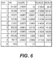
- a similar table may be generated for the second embodiment, as shown in FIG. 6 .
- the difference between successive steps for the logarithmic value is no longer constant (unlike for the first embodiment), but regardless it is still preferable to use the non-constant logarithmic values than the linear LWS values.
- the use of a logarithmic light sensor (such as, but not limited to, the OSRAM SFH 5711) is preferable to a linear light sensor.
- the final step is to acknowledge that the Silverstein equation only takes into consideration the reflected background luminance. However, it is also necessary to consider the forward looking luminance, particularly in the automotive situation (as well as other situations).
- the visibility performance of the display may be further improved by including a forward looking light sensor 24 which may be remotely located (as shown in FIG. 5 ) to compensate for conditions of transient adaption or eye adaption mismatch as a result of the user 28 looking back and forth from the exterior of the automobile to the electronic display.
- the forward looking light sensor 24 faces forwards in the same direction as the forwards oriented view of the user 28.
- the senor 24 is configured to detect light external light relative to the passenger compartment and therefore provides a measure of light from an external light source 22 (in this example, the sun) entering the vehicle compartment and directed towards the eyes of the user 28.
- an external light source 22 in this example, the sun
- the forward looking light sensor 24 is within the vehicle compartment, behind a windscreen.
- FIG. 7 An implementation of the system (see e.g., FIGS. 5 and 7 ), but using logarithmic light sensors (i.e., forward looking and ambient), (such as the OSRAM SFH 5711) in place of linear light sensors is shown in FIG. 7 .
- logarithmic light sensors i.e., forward looking and ambient
- FIG. 7 accomplishes automatic luminance control where the display luminance is changed as a function of the lighting conditions rather than holding the display luminance constant and changing the transmission of the dimmable lens 12.
- the implementation of the system shown in FIG. 8A may be modified to adjust the transmission rather than the display luminance and is illustrated in FIG. 8B .
- the user/driver 28 may select a bias by a selected number of luminance ratios (see FIG. 8A ) or transmission ratios (see FIG. 8B ).
- the operational curve of the LC cell forming the dimmable lens 12 shifts substantially over automotive operational temperature ranges (e.g., winter and summer climates).
- the LC cell must be driven AC (alternating current) in order to prevent charge migration to one of the LC cell's internal surfaces.
- One embodiment to drive the LC cell may use two microprocessor counter outputs to generate the drive voltages to the final differential driving transistors.
- the peak-to-peak voltage may be controlled by the voltage source via a potentiometer circuit, however a PWM (pulse width modulator) output from a microprocessor with an interface circuit(s).
- transmissive feedback dimming are only exemplary and not limiting.
- the transmissive active dimming disclosed herein may be applied to any optical structure capable of the dimming function.
- While one or more embodiments may utilize a guest-host LC cell, other configurations capable of the dimming function may also be utilized.
- the transfer function of the LC cell is known to be fairly steep and varies with temperature. Since the transmission rate varies significantly with temperature and LC cell-to-cell variation, a feedback control mechanism is required to maintain precise control of the transmission rate of the LC cell (i.e., dimmable lens 12).
- a transmission rate light source 36 such as, but not limited to, a light emitting diode (LED) is disposed on the exterior surface of the dimmable lens 12.
- the transmission rate light source 36 is provided on the separate segment 30, being mounted on an external surface of a layer of the dimmable lens which is common to both a main segment through which the viewer views an image provided by the display element, and the separate segment 30.
- the transmission rate light source 36 is configured to emit light L through the dimmable lens 12 toward a transmission rate light sensor 38.
- the transmission rate light sensor 38 is provided on the separate segment 30, being mounted on an external surface of a layer of the dimmable lens which is common to both a main segment through which the viewer views an image provided by the display element, and the separate segment 30.
- the transmission rate light source 36 can include visible and/or invisible spectral radiation LEDs, for example.
- a separate segment 30 of dimmable lens 12 is disposed adjacent to the transmission rate light source 36 and the transmission rate light sensor 38. The separate segment 30 is used as part of an automatic dimming lens control system 50 of the dimmable display lens system 10 with the maximum and operational transmission rates of the dimmable lens 12 using the transmission rate light source 36 and/or the transmission rate light sensor 38.
- FIG. 9B illustrates a reflection based control system.
- the transmission rate light source 36 is disposed on the interior surface of the dimmable lens 12, on the same side that is facing the electronic display 16.
- the air gap 32 is disposed between the dimmable lens 12 and the display 16.
- the transmission rate light source 36 is configured to emit light L through the dimmable lens 12 to a reflector 34 disposed on the opposite (i.e., exterior), side of the dimmable lens 12.
- the light L emitted by the transmission rate light source 36 reflects off of the reflector 34 and back through the dimmable lens 12 to the transmission rate light sensor 38, which is disposed adjacent to the transmission rate light source 36.
- the separate segment 30 may be omitted, with the maximum and operational transmission rates being determined and/or estimated by the control system of the dimmable display lens system 10.
- FIGS. 9C - 9D illustrate using the luminance from the dimmable lens 12 to determine the transmission rate.
- FIGS. 9C - 9D generally illustrate the dimmable lens 12 with the air gap 32 disposed between the dimmable lens 12 and the electronic display 16.
- the control system of the dimmable lens display system 10 utilizes the luminance from the display 16 to determine the transmission rate of the dimmable lens 12.
- the separate segment 30 is disposed to overlap a portion of the output (i.e., luminance) area of the electronic display 16.
- the portion of the output area of the display 16 may or may not be visible to the driver/user/operator 28 of the vehicle.
- a unique output from the display element may be used (i.e., a test pattern), that the control system of the dimmable lens display system 10 uses to determine the transmission rate of the dimmable lens 12.
- the portion of the output area of the display 16 includes the viewable area.
- the light L from the display 16 (rather than from an independent transmission rate light source 36 as in FIGS.
- the transmission rate light sensor 38 can be disposed within the air gap 32 between the dimmable lens 12 and the display 16.
- the separate segment 30 is disposed to overlap a portion of the output area of the display 16.
- the separate segment 30 may include a unique output (i.e. a test pattern) from the display 16 and/or a portion of the viewable output from the display 16.
- a bezel or surround may at least partially conceal the separate segment 30 and/or the transmission rate light sensor 38 from the viewer.
- the light L from the display 16 passes through the separate segment 30 of the dimmable lens 12 to the transmission rate light sensor 38 disposed on the opposite side of the dimmable lens 12.
- the control system of the dimmable display lens system 10 utilizes the luminance output of the display 16 to determine the transmission rate of the dimmable lens 12.
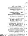
- FIG. 10 generally illustrates a block diagram of the automatic dimming lens control system 50 for the dimmable display lens system 10.
- the automatic dimming lens control system 50 is configured in block 52 such that the luminance of the display 16 is constant and the transmission rate of the dimmable lens 12 is automatically adjusted to a predetermined visibility level in block 54.
- the darkest setting i.e., lowest transmission rate
- dimmable lens 12 can be used for low ambient light conditions (i.e., night time).
- the constant display luminance may be reduced further to obtain reductions in the display luminance for night time conditions.
- the automatic dimming lens control system 50 is configured to adjust the transmission rate of the dimmable lens 12 in steps that appear equal to the human eye.
- a constant transmission step table can be used that will be perceived by the human eye as linear.
- other step configurations can be used, such as non-linear, arbitrary, random, or based on a predetermined function.
- the automatic dimming lens control system 50 generates, for example, a stepped constant ratio transmission rate lookup table where the transmission rate is selected based on the ambient and forward looking logarithmic light sensors.
- the number of steps can vary, but for example, ten steps can be used to move from a transmission rate of 0.2 to 0.7, with 0.2 indicating the lowest amount of light transmission from the display 16 through dimmable lens 12. Due the constant step ratio nature of the lookup table, adjustments to the transmission rate of the dimmable lens 12 by the automatic dimming lens control system 50 appear to a human viewer to be of equal value (i.e., linear), even though mathematically the values of each step are constant ratios and not linear. By changing the transmission rate of the dimmable lens 12 according to constant ratio transmission steps, the viewer will not perceive a sudden or shocking change to the luminance of the display 16 when viewed through the dimmable lens 12.
- an additional factor is added to the determination of the transmission rate by the automatic dimming lens control system 50.
- the luminance of ambient light reflections is measured using the ambient light sensor 26 that may be logarithmic.
- the luminance is a factor in determining the transmission rate of the dimmable lens 12 by the automatic dimming lens control system 50 due the light reflected back from the dimmable lens 12 from an exemplary lightly colored surface, such as lightly-colored leather seats in the vehicle. This reflected luminance impacts the visibility of the display 16 through the dimmable lens 12 by a viewer. For example, the viewer, such as a driver 28, in bright sunlight can reflect a high level of light toward the dimmable lens 12.
- the transmission rate of the dimmable lens 12 is then adjusted to compensate for the ambient light reflected onto the dimmable lens 12.
- the resulting higher transmission step for the dimmable lens 12 allows more light to pass through from the display 16 to the viewer to overcome the "glare" reflected to the eyes of the driver/viewer 28.
- the forward looking light sensor 24 (see FIG. 6 ), which may be logarithmic, is configured to compensate the transmission rate of the dimmable lens 12 for the viewer temporary eye adaptation or discrepancies in human eye adaptation.
- the viewer may be looking at a high luminance/reflectivity object (e.g., the sun, oncoming headlights), due to the limitations of the human eye, adjustments by the viewer to perceive a lower luminance display 16 with the dimmable lens 12 can be problematic.
- the automatic dimming lens control system 50 compensates for this situation and adjusts the transmission rate of the dimmable lens 12 accordingly.
- the automatic dimming lens control system 50 adjusts the transmission rate of the dimmable lens 12 to a higher value, resulting in less of a dimming effect, so that the viewer can perceive the display 16 despite the high luminance/reflectively object impacting the vision of the viewer.
- the automatic dimming lens control system 50 determines the transmission rate of the dimmable lens 12 by processing the predetermined transmission rate of the dimmable lens 12 (e.g., on vehicle startup), and factoring in the ambient reflection and forward look values. For example, if the original transmission rate for the dimmable lens is 0.2 (the display 16 is relatively dim to the viewer), but the ambient reflection and/or forward look values impact (i.e., revise), the transmission rate lookup table values, then the new transmission rate for the dimmable lens 12 is a value corresponding to a higher transmission rate such as 0.3 (the display 16 is brighter relative to the viewer).
- the automatic dimming lens control system 50 adjusts the transmission rate of the dimmable lens 12 according to the determination in block 64.
- the automatic dimming lens control system 50 adjusts the dimmable lens 12 transmission rate according to the updated lookup table, including the initial transmission rate value and any changes due to measurements of the ambient reflection sensor 26 and forward looking light sensor 24, if any. If there are no changes required (i.e., the initial (or present) value is confirmed by the lookup table), then the automatic dimming lens control system 50 maintains the present value of the dimmable lens 12 transmission rate. If there are changes required (i.e., the initial/present value is different than the revised lookup table indicates), then the automatic dimming lens control system 50 adjusts the dimmable lens 12 transmission rate accordingly.
- the automatic dimming lens control system 50 also includes a feedback control system 100.
- the feedback control system 100 is required due to the operational temperature ranges of the display 16 located in a vehicle. In order to maintain precise control of the transmission rate of the dimmable lens 12, the feedback control system 100 compensates for changes in transmission versus voltage applied to the dimmable lens 12 over the transmission rate range and the aforementioned temperature impact on the dimmable lens 12.
- the voltage applied to the dimmable lens 12 is adjusted to control the effective transmission rate using the feedback control system 100.
- the feedback control system 100 includes a digital proportional-integral-derivative (PID) loop, an analog loop, or a combination of both.
- PID digital proportional-integral-derivative
- the feedback control loop to accurately control the transmission rate value of the dimmable lens 12 begins at block 112.
- the block 112 is configured to either apply the voltage V LCD of the display 16 or the maximum voltage V MAX of the display 16 to the separate segment 30 (see FIGS. 9A - 9D ) in an alternating fashion.
- the block 116 generates the transmission rate of a transfer function of the dimmable lens 12 in the separate segment 30.
- the voltage i.e., V LCD or V MAX
- the luminance transmission from the transmission rate light source 36 is measured by the transmission rate light sensor 38 in front of the separate segment 30.
- the luminance transmission from the transmission rate light source 36 is also measured by the transmission rate light sensor 38 in front of the separate segment 30.
- the block 124 receives input of the luminance value 122 of the transmission rate light source 36 and outputs the maximum luminance L MAX at maximum voltage V MAX and the luminance measured at the predetermined voltage L VLCD .
- the actual dimmable lens 12 transmission value is calculated by multiplying the maximum transmission rate T MAX by the ratio between the measured luminance L VLCD of the dimmable lens 12 and the maximum luminance L MAX of the dimmable lens 12.
- a transmission rate error T Error is determined by block 104 by subtracting the desired transmission rate TCommand from the feedback transmission rate T VLCD . For example, if a higher transmission rate is requested by the automatic dimming lens control system 50, the transmission rate error increases and the luminance of the dimmable lens 12 increases. In other words, a proportion of the T Error is added back to the T Command value. As a result, the transmission rate calculation increases in block 120.
- the same display 16 voltage V LCD is also used by block 108 to drive segments of the display 16 that are visible to the viewer and implement the desired transmission rate on those areas of the display 16.
- the use of the separate segments 30 for determining the transmission rate can provide a more accurate feedback control loop, omitting the separate segments 30 can still provide a functional and less complex feedback control loop configuration.
Landscapes
- Physics & Mathematics (AREA)
- Nonlinear Science (AREA)
- General Physics & Mathematics (AREA)
- Optics & Photonics (AREA)
- Crystallography & Structural Chemistry (AREA)
- Chemical & Material Sciences (AREA)
- Mathematical Physics (AREA)
- Engineering & Computer Science (AREA)
- Computer Hardware Design (AREA)
- Theoretical Computer Science (AREA)
- Control Of Indicators Other Than Cathode Ray Tubes (AREA)
- Liquid Crystal (AREA)
- Devices For Indicating Variable Information By Combining Individual Elements (AREA)
Abstract
Description
- Automotive displays can be used to provide visual information throughout a vehicle. These displays can be located in an instrument panel to provide information about the vehicle that a driver or operator may want to be aware of, such as speed, fuel/energy remaining, etc. Additionally, displays can be located in other parts of the vehicle, such as the center console, seat backs for entertainment, and interior and exterior surfaces of the vehicle doors. However, these displays may not always include viewable information, particularly when the vehicle is in an off state (i.e., low or no power in the vehicle).
- A dimmable display lens system is provided which includes a display element configured to emit light. A dimmable lens is disposed in the direction of light emission of the display element. The dimmable lens is configured to reduce the transmission of light emitted by the display through the dimmable lens. The dimmable lens includes a control system configured to reduce the transmission of light emitted by the display according to a plurality of light transmission reduction steps. The control system includes a control system configured to adjust the transmission of light through the dimmable lens based on at least a light sensor and a light source measuring light transmission through the dimmable lens.
- In one embodiment, there is provided a dimmable display lens system, the system comprising:
- a display element, the display element being configured to emit light; and
- a dimmable lens, the dimmable lens being disposed in the direction of light emission of the display element and being configured to transmit light emitted by the display element through the dimmable lens towards a viewer,
- wherein the dimmable lens display system further comprises an automatic dimming lens control system configured to change the transmission of light emitted by the display according to a plurality of light transmission incremental steps,
- wherein the automatic dimming lens control system includes a feedback control system configured to adjust the transmission of light through the dimmable lens based at least on the measured values of a first light sensor and a second light sensor, the first light sensor being an ambient light sensor and the second light sensor being a forward looking light sensor relative to said viewer.
- Preferably, the first light sensor is oriented towards the viewer. The ambient light then includes ambient light reflected or scattered from the viewer. The measure of ambient light provided by the first light sensor is then a measure of reflections from one or more surfaces of the dimmable lens (e.g. the external surface and/or internal surfaces) which the viewer may see superimposed on images provided by the display element.
- In a preferred embodiment, the dimmable display lens system is provided within a motor vehicle passenger compartment. The viewer may be a driver of the vehicle, in which case the display element may be part of a dashboard display. Alternatively, the viewer may be a passenger, in which case the display element may be part of an entertainment or information display system.
- In a preferred embodiment, the automatic dimming lens control system comprises a segment of the dimmable lens which overlaps an output area of the dimmable lens through which light from the display element is transmitted. A viewer views output from the display element through a main segment of the output area. The separate segment is preferably provided to one side of the main segment of the dimmable lens. The main segment and the separate segment may share a common layer which extends laterally across the extent of the dimmable lens.
- When the dimmable display lens system is provided within a motor vehicle passenger compartment, the ambient light will be ambient light within the motor vehicle passenger compartment, and the light detected by the forward looking light sensor will be predominantly or entirely external light directed into the passenger compartment. Particularly in the daytime, the intensity of such external light will be the main factor in the degree of dilation of the viewer's pupils.
- A method is provided of controlling a dimmable display lens disposed in the direction of light emission of a display element, the method comprising: setting the light emission of the display element to a constant value; generating a lookup table containing a plurality of light transmission incremental steps using a minimum transmission level of the dimmable display lens, a maximum transmission level of the dimmable display lens, and a predetermined number of light transmission incremental steps; selecting a light transmission incremental step from the lookup table; and adjusting the transmission of light emitted by the display element through the dimmable display lens according to the selected incremental step. The method may also include measuring ambient light to generate a transmission ratio lookup table and forward looking light to generate a luminance ratio table for transmission ratio table adaption control. The method may also include using a light source to project light through a segment of the dimmable display lens to a light sensor to measure the maximum transmission level via feedback control. The method may also include estimating the maximum transmission level or determining the maximum transmission level during startup of the dimmable display lens and the display element.
- Also described herein is a non-transient computer readable medium containing program instructions for causing a computer to perform the method of: setting the light emission of the display element to a constant value; generating a lookup table containing a plurality of light transmission incremental steps using a minimum transmission level of the dimmable display lens, a maximum transmission level of the dimmable display lens, a predetermined number of light transmission incremental steps and a selected light transmission incremental step; and adjusting the transmission of light emitted by the display element through the dimmable display lens according to the selected incremental step.
- The non-transient computer readable medium containing program instructions may also include the method of measuring ambient light to generate a transmission ratio lookup table and forward looking light to generate a luminance ratio table for transmission ratio table adaption control.
- The non-transient computer readable medium containing program instructions may also include the method of: using a light source to project light through a segment of the dimmable display lens to a light sensor to measure the maximum transmission level.
- The non-transient computer readable medium containing program instructions may also include the method of: estimating the maximum transmission level or determining the maximum transmission level during startup of the dimmable display lens and the display element.
- Further details, features and advantages of designs of the invention result from the following description of embodiment examples in reference to the associated drawings.
-
FIGS. 1A - 1B are schematic views of an embodiment of the dimmable lens display system including an optically bonded dimmable lens and an embodiment of the dimmable lens display system including an air gap dimmable lens, respectively, in accordance with the present disclosure; -
FIG. 2 is a chart plotting the level of lens transmission versus the display luminance of the embodiments ofFIGS. 1A and 1B in accordance with the present disclosure; -
FIG. 3 is an exemplary constant ratio transmission step table in accordance with the present disclosure; -
FIG. 4 is an exemplary automatic transmission control look-up table for the embodiment ofFIG. 1A in accordance with the present disclosure; -
FIG. 5 is a schematic view of an embodiment of a dimmable lens display system disposed in an automobile in accordance with the present disclosure; -
FIG. 6 is an exemplary automatic transmission control look-up table for the embodiment ofFIG. 1B in accordance with the present disclosure; -
FIG. 7 is a block diagram of an automatic display luminance system; -
FIG. 8A is an exemplary block diagram of an automatic luminance control system using logarithmic light sensors in accordance with the present disclosure; -
FIG. 8B is an exemplary block diagram of an automatic dimming control system using logarithmic light sensors in accordance with the present disclosure; -
FIG. 9A is a perspective view of an embodiment of a dimmable lens display system in accordance with the present disclosure; -
FIG. 9B is a perspective view of an alternative embodiment of a dimmable lens display system in accordance with the present disclosure; -
FIG. 9C is a perspective view of an alternative embodiment of a dimmable lens display system in accordance with the present disclosure; -
FIG. 9D is a perspective view of an alternative embodiment of a dimmable lens display system in accordance with the present disclosure; -
FIG. 10 is a block diagram of a luminance control system of a dimmable lens display system in accordance with the present disclosure; and -
FIG. 11 is a block diagram of a dimming feedback control system of the dimmable lens display system in accordance with the present disclosure. - Recurring features are marked with identical reference numerals in the figures. A dimmable
lens display system 10 is disclosed. - The term "lens" as used herein is conventionally used in the technical field of displays to mean a substantially transparent layer or sheet, which may be clear or colored and either planar or curved, and which may be provided separately or in conjunction with other layers, and positioned between the viewer and display elements for providing information to the viewer.
- The dimmable lens display system comprises a
dimmable lens 12 which controllably attenuates light transmitted through the lens towards a viewer. The transmission of thedimmable lens 12 is preferably controllable between a substantially transparent state and a substantially opaque state. - Automotive electronic displays (i.e., video screens), are increasingly common for use in the instrument cluster and/or for center stack displays. Additionally, automotive electronic displays are being employed in other areas of the automobile, such as doors, outside entry (e.g., keypads), rear seat entertainment and/or passenger entertainment applications. Often for styling (i.e., appearance), reasons it is desirable to have an electronic display hidden in a key-off (e.g., vehicle off), condition. This appearance is typically accomplished using a neutral density filter with a very low transmission value. However, the very low transmission value leads to very high display luminance values for a user to be able to see the electronic display images under high ambient light conditions. One approach to lower the display luminance is to use an anti-reflection coating. However, anti-reflection coatings are prone to highlight user fingerprints and therefore are typically not desirable from an appearance standpoint. Another approach is to use a dimmable lens in front of the electronic display. In this approach, in the key-off condition, the dimmable lens may be configured to be in a low transmission (dark) state in which the dimmable lens absorbs substantially all of the light which enters the dimmable lens. When in a key-on condition, the dimmable lens may be automatically adjusted for desired electronic display visibility with an objective to keep the dimmable lens as dark as possible.
- One or more embodiments may be directed toward an electro-optical system and method to control the transmission of light through a dimmable lens element located in front of an electronic display. There are several types of dimmable lens elements (i.e., displays), such as, but not limited to, suspended particle devices (SPDs), electrochromic (EC) and dye-doped guest-host liquid crystal (LC) systems. These systems typically require accurate control system (i.e., drivers), to control the amount of absorption of light by the dimmable lens and hence the transmission rate of the dimmable lens. One or more embodiments may use as an example the dye-doped LC system, though any of the other described systems and other display systems may be used.
- Among other things, one or more embodiments may describe the use of a dimmable lens located in front of an electronic display to reduce the luminance of the electronic display, an automatic transmission control methodology, and an accurate dimmable lens transmission rate control using feedback control systems and methods.
- Two exemplary embodiments are disclosed to address the situation that less electronic display luminance is required as the lens transmission is increased. The first embodiment is an optically bonded lens. The second embodiment is an air gap bonded lens. Each will be discussed in turn.
- For the first embodiment, the optically bonded lens, a number of assumptions are made, including an optically bonded
dimmable lens 12, a shiny (i.e. optically flat or optically smooth)front surface 18 at 4% reflectance, white shirt reflectance, and white shirt luminance at 10,000 nits. (A "nit" is a unit of visible light intensity, commonly used to specify the brightness of an electronic display. One nit is equivalent to one candela per square meter.) -
FIG. 1A illustrates the first embodiment of a dimmablelens display system 10. Thedimmable lens 12 is joined via anoptical bond 14 to a display element, which in this example is anelectronic display 16. Light L is shown striking thedimmable lens 12, with 4% reflecting off of the shinyfront surface 18 of thedimmable lens 12. - The Silverstein visibility function (developed by Dr. Louis D. Silverstein) relates the amount of required display luminance to the background luminance by the following equation:

- Where ESL represents the emitted symbol luminance in cd (candela)/m2, Bo represents the luminance offset constant, DBL represents the display background luminance in cd/m2, and C represents the power constant (the slope of the power function in logarithmic coordinates).
- The electronic display background luminance (BGL) that a viewer or user 28 (see e.g.,
FIG. 5 ) would see for the white shirt reflection from the shiny front surface of the dimmable lens 12 (seeFIG. 1A ) may be calculated using the following equation where 10K nits is an exemplary luminance of a white shirt when sunlight is shining on the white shirt:
- Assuming no reflection due the
optical bond 14, the required emitted display luminance (ESL) may be calculated using the following equation:
- Due to the
optical bond 14 and the elimination of reflections behind the front of thedimmable lens 12, it is preferable to use a less opaque lens. For example, an electronic "normally-black" tinting system can be configured for different doping levels. Normally,-black refers to a condition when no power is applied to thedimmable lens 12; thedimmable lens 12 then defaults to its most opaque condition. - For example, a doping level may be selected for the most dynamic range of about Tint On = 70% and Tint Off = 20%. Operating the
dimmable lens 12 at a 70% transmission results in reducing the thin film transistor (TFT) electronic display luminance compared to a 20% static transmission lens. The required emitted symbol luminance (ESL) values for Tint On and Tint Off are determined by dividing by the two transmission rates:

- The calculated values above establish that the display luminance can be reduced by 1286 nits from 1800 nits to 515.26 nits if the
dimmable lens 12 is utilized. If the lens transmission value T is used with the Silverstein visibility function (ESL = BO (DBL)C), a new equation is developed to calculate for the first embodiment where LD represents the display luminance alone, without the dimmable lens 12:
- For the second embodiment, the
dimmable lens 12 with anair gap 32, a number of assumptions are made, including adimmable lens 12 with anair gap 32 with two 4% internal reflectance interfaces 20, a shiny front surface at 4% reflectance, white shirt reflectance, and white shirt luminance at 10,000 nits. -
FIG. 1B illustrates the second embodiment of a dimmablelens display system 10. Thedimmable lens 12 is situated with anair gap 32 separating theelectronic display 16. Light L is shown striking thedimmable lens 12, with 4% reflecting off of the shinyfront surface 18 and the two 4% internal reflectance interfaces 20. - The display background luminance (BGL) that the user 28 (see e.g.,
FIG. 5 ) would see for the white shirt reflection from the shinyfront surface 18 of thedimmable lens 12 is calculated using the following equation:
- The required emitted display luminance (ESL) is calculated using the following equation:

- A new equation is developed to calculate the system performance for the second embodiment in terms of transmission T and display luminance LD:

- The graph of
FIG. 2 plots the required display luminance as a function of lens transmission for the first and second embodiments (as shown inFIGS. 1A and 1B ). As the graph ofFIG. 2 illustrates, the second embodiment requires more display luminance due to the air gap internal reflections. However, in both embodiments a lower ambient lighting level results in a lower required display luminance. Therefore, thedimmable lens 12 may be used to change (i.e. to increase and to decrease) the lens transmission as a function of ambient lighting levels. - In order to operate either embodiment automatically, it is preferable that the display luminance is constant and the lens transmission level is adjusted for user visibility, depending on the ambient lighting level, with the exception of night time ambient lighting levels, when the display luminance may need to be reduced below a constant set illuminance appropriate for day time ambient lighting levels, owing to the minimum luminance (maximum absorption) provided by the dimmable lens being insufficient to reduce the display brightness to a comfortable viewing level when the viewer's pupils are dilated. As a result, the
dimmable lens 12 at its darkest setting may be used across a range of relatively low ambient lighting conditions. Additionally, ratio changes in transmission level will appear to the user 28 (see e.g.,FIG. 5 ) as equal steps due to the logarithmic nature of the eyes of theuser 28. To develop automatic transmission control look-up tables, the following equation may be used to determine the transmissions as a function of the number of desired steps:
- Where TSEL represents the transmission of step number N, TMAX represents the maximum transmission level, TMIN represents the minimum transmission level, Nt represents the total number of steps, and N represents the selected step number.
- For example, if a 10-step look-up table is constructed, the above equation may be used to calculate the transmission levels of the dimmable lens for the various step numbers as shown in the table of
FIG. 3 . Note that the transmission ratio of successive steps (e.g., the ratio betweenstep 2 and 3), is a constant value. - The next step in generation of the automatic transmission control table is to calculate the ambient lumination value (e.g., white shirt luminance (LWS) value), that is proportional to a light sensor (see
FIG. 4 ) output of an ambient light sensor 26 (seeFIG. 5 ). For the first embodiment, this is accomplished by substituting LWS for 400 and 515.26 for LD in the earlier equation:

- The previous equation is used to calculate the white shirt luminance values for each of the 10 steps, as shown in
FIG. 4 . - As the ambient
light sensor 26 output is directly proportional to the white shirt luminance (LWS), it is instructive to examine the difference in the LWS value between successive steps (e.g., betweensteps 2 and 3), as shown in the table ofFIG. 4 . The LWS difference is small for the lower steps (i.e., steps 1-4) and large for the upper steps (i.e., steps 7-10). For the lower steps, the small differences cause small analog/digital (A/D) converter differences which is not ideal from a resolution and/or noise perspective. In order to avoid these issues, it is preferable to use a logarithmic light sensor such as the OSRAM SFH 5711 by OSRAM Licht AG. If the logarithmic values of the LWS are calculated, the difference between successive logarithmic values becomes a constant as shown in the chart ofFIG. 4 . Using the logarithmic values results in equal A/D converter differences and avoids the earlier issues described above with a linear light sensor. - For the second embodiment, a similar process used for the first embodiment can be used, including the calculation of the white shirt luminance (LWS) using a modified equation for the second embodiment:

- A similar table may be generated for the second embodiment, as shown in
FIG. 6 . In this second embodiment, the difference between successive steps for the logarithmic value is no longer constant (unlike for the first embodiment), but regardless it is still preferable to use the non-constant logarithmic values than the linear LWS values. As a result, the use of a logarithmic light sensor (such as, but not limited to, the OSRAM SFH 5711) is preferable to a linear light sensor. - The final step is to acknowledge that the Silverstein equation only takes into consideration the reflected background luminance. However, it is also necessary to consider the forward looking luminance, particularly in the automotive situation (as well as other situations). In addition to increasing the display luminance as a function of the reflected display background luminance measured by the ambient
light sensor 26, which is configured to detect ambient light within the passenger compartment, the visibility performance of the display may be further improved by including a forward lookinglight sensor 24 which may be remotely located (as shown inFIG. 5 ) to compensate for conditions of transient adaption or eye adaption mismatch as a result of theuser 28 looking back and forth from the exterior of the automobile to the electronic display. The forward lookinglight sensor 24 faces forwards in the same direction as the forwards oriented view of theuser 28. In this manner, thesensor 24 is configured to detect light external light relative to the passenger compartment and therefore provides a measure of light from an external light source 22 (in this example, the sun) entering the vehicle compartment and directed towards the eyes of theuser 28. In this example, the forward lookinglight sensor 24 is within the vehicle compartment, behind a windscreen. - An implementation of the system (see e.g.,
FIGS. 5 and7 ), but using logarithmic light sensors (i.e., forward looking and ambient), (such as the OSRAM SFH 5711) in place of linear light sensors is shown inFIG. 7 . However, the implementation shown inFIG. 7 accomplishes automatic luminance control where the display luminance is changed as a function of the lighting conditions rather than holding the display luminance constant and changing the transmission of thedimmable lens 12. The implementation of the system shown inFIG. 8A may be modified to adjust the transmission rather than the display luminance and is illustrated inFIG. 8B . For both implementations, the user/driver 28 may select a bias by a selected number of luminance ratios (seeFIG. 8A ) or transmission ratios (seeFIG. 8B ). - In order to accurately control the transmission level of the
dimmable lens 12, a feedback method is required. The operational curve of the LC cell forming thedimmable lens 12 shifts substantially over automotive operational temperature ranges (e.g., winter and summer climates). The LC cell must be driven AC (alternating current) in order to prevent charge migration to one of the LC cell's internal surfaces. One embodiment to drive the LC cell may use two microprocessor counter outputs to generate the drive voltages to the final differential driving transistors. For example, the peak-to-peak voltage may be controlled by the voltage source via a potentiometer circuit, however a PWM (pulse width modulator) output from a microprocessor with an interface circuit(s). - The embodiments provided herein for transmissive feedback dimming are only exemplary and not limiting. The transmissive active dimming disclosed herein may be applied to any optical structure capable of the dimming function.
- While one or more embodiments may utilize a guest-host LC cell, other configurations capable of the dimming function may also be utilized. The transfer function of the LC cell is known to be fairly steep and varies with temperature. Since the transmission rate varies significantly with temperature and LC cell-to-cell variation, a feedback control mechanism is required to maintain precise control of the transmission rate of the LC cell (i.e., dimmable lens 12).
- Referring now to
FIG. 9A , a transmission based system is shown. A transmission ratelight source 36, such as, but not limited to, a light emitting diode (LED) is disposed on the exterior surface of thedimmable lens 12. The transmission ratelight source 36 is provided on theseparate segment 30, being mounted on an external surface of a layer of the dimmable lens which is common to both a main segment through which the viewer views an image provided by the display element, and theseparate segment 30. - The transmission rate
light source 36 is configured to emit light L through thedimmable lens 12 toward a transmissionrate light sensor 38. The transmissionrate light sensor 38 is provided on theseparate segment 30, being mounted on an external surface of a layer of the dimmable lens which is common to both a main segment through which the viewer views an image provided by the display element, and theseparate segment 30. - The transmission rate
light source 36 can include visible and/or invisible spectral radiation LEDs, for example. Aseparate segment 30 ofdimmable lens 12 is disposed adjacent to the transmission ratelight source 36 and the transmissionrate light sensor 38. Theseparate segment 30 is used as part of an automatic dimminglens control system 50 of the dimmabledisplay lens system 10 with the maximum and operational transmission rates of thedimmable lens 12 using the transmission ratelight source 36 and/or the transmissionrate light sensor 38. -
FIG. 9B illustrates a reflection based control system. The transmission ratelight source 36 is disposed on the interior surface of thedimmable lens 12, on the same side that is facing theelectronic display 16. Theair gap 32 is disposed between thedimmable lens 12 and thedisplay 16. The transmission ratelight source 36 is configured to emit light L through thedimmable lens 12 to areflector 34 disposed on the opposite (i.e., exterior), side of thedimmable lens 12. The light L emitted by the transmission ratelight source 36 reflects off of thereflector 34 and back through thedimmable lens 12 to the transmissionrate light sensor 38, which is disposed adjacent to the transmission ratelight source 36. According to one or more embodiments, the separate segment 30 (seeFIGS. 9A - 9D ) may be omitted, with the maximum and operational transmission rates being determined and/or estimated by the control system of the dimmabledisplay lens system 10. -
FIGS. 9C - 9D illustrate using the luminance from thedimmable lens 12 to determine the transmission rate.FIGS. 9C - 9D generally illustrate thedimmable lens 12 with theair gap 32 disposed between thedimmable lens 12 and theelectronic display 16. In the embodiments shown inFIGS. 9C - 9D , the control system of the dimmablelens display system 10 utilizes the luminance from thedisplay 16 to determine the transmission rate of thedimmable lens 12. - In
FIG. 9C , theseparate segment 30 is disposed to overlap a portion of the output (i.e., luminance) area of theelectronic display 16. It should be understood that the portion of the output area of thedisplay 16 may or may not be visible to the driver/user/operator 28 of the vehicle. A unique output from the display element may be used (i.e., a test pattern), that the control system of the dimmablelens display system 10 uses to determine the transmission rate of thedimmable lens 12. In other embodiments, the portion of the output area of thedisplay 16 includes the viewable area. The light L from the display 16 (rather than from an independent transmission ratelight source 36 as inFIGS. 9A - 9B passes through thedimmable lens 12 and is reflected by thereflector 34 to the transmissionrate light sensor 38 disposed on thedimmable lens 12 on the opposite side of thereflector 34. The transmissionrate light sensor 38 can be disposed within theair gap 32 between thedimmable lens 12 and thedisplay 16. - In
FIG. 9D , theseparate segment 30 is disposed to overlap a portion of the output area of thedisplay 16. As discussed above, theseparate segment 30 may include a unique output (i.e. a test pattern) from thedisplay 16 and/or a portion of the viewable output from thedisplay 16. For example, a bezel or surround (not shown) may at least partially conceal theseparate segment 30 and/or the transmissionrate light sensor 38 from the viewer. The light L from thedisplay 16 passes through theseparate segment 30 of thedimmable lens 12 to the transmissionrate light sensor 38 disposed on the opposite side of thedimmable lens 12. In bothFIGS. 9C - 9D , the control system of the dimmabledisplay lens system 10 utilizes the luminance output of thedisplay 16 to determine the transmission rate of thedimmable lens 12. -
FIG. 10 generally illustrates a block diagram of the automatic dimminglens control system 50 for the dimmabledisplay lens system 10. The automatic dimminglens control system 50 is configured inblock 52 such that the luminance of thedisplay 16 is constant and the transmission rate of thedimmable lens 12 is automatically adjusted to a predetermined visibility level inblock 54. For example, the darkest setting (i.e., lowest transmission rate), fordimmable lens 12 can be used for low ambient light conditions (i.e., night time). Once the minimum output luminance is obtained at the lowest dimmable lens transmission rate, the constant display luminance may be reduced further to obtain reductions in the display luminance for night time conditions. - In
block 56, the automatic dimminglens control system 50 is configured to adjust the transmission rate of thedimmable lens 12 in steps that appear equal to the human eye. However, as the human eye is not capable of perceiving linear steps as equal, a constant transmission step table can be used that will be perceived by the human eye as linear. Additionally, or alternatively, other step configurations can be used, such as non-linear, arbitrary, random, or based on a predetermined function. - In
block 58, the automatic dimminglens control system 50 generates, for example, a stepped constant ratio transmission rate lookup table where the transmission rate is selected based on the ambient and forward looking logarithmic light sensors. The number of steps can vary, but for example, ten steps can be used to move from a transmission rate of 0.2 to 0.7, with 0.2 indicating the lowest amount of light transmission from thedisplay 16 throughdimmable lens 12. Due the constant step ratio nature of the lookup table, adjustments to the transmission rate of thedimmable lens 12 by the automatic dimminglens control system 50 appear to a human viewer to be of equal value (i.e., linear), even though mathematically the values of each step are constant ratios and not linear. By changing the transmission rate of thedimmable lens 12 according to constant ratio transmission steps, the viewer will not perceive a sudden or shocking change to the luminance of thedisplay 16 when viewed through thedimmable lens 12. - In
block 60, an additional factor is added to the determination of the transmission rate by the automatic dimminglens control system 50. The luminance of ambient light reflections is measured using the ambientlight sensor 26 that may be logarithmic. The luminance is a factor in determining the transmission rate of thedimmable lens 12 by the automatic dimminglens control system 50 due the light reflected back from thedimmable lens 12 from an exemplary lightly colored surface, such as lightly-colored leather seats in the vehicle. This reflected luminance impacts the visibility of thedisplay 16 through thedimmable lens 12 by a viewer. For example, the viewer, such as adriver 28, in bright sunlight can reflect a high level of light toward thedimmable lens 12. The transmission rate of thedimmable lens 12 is then adjusted to compensate for the ambient light reflected onto thedimmable lens 12. The resulting higher transmission step for thedimmable lens 12 allows more light to pass through from thedisplay 16 to the viewer to overcome the "glare" reflected to the eyes of the driver/viewer 28. - In
block 62, an additional factor is added to the determination of the transmission rate by the automatic dimminglens control system 50. The forward looking light sensor 24 (seeFIG. 6 ), which may be logarithmic, is configured to compensate the transmission rate of thedimmable lens 12 for the viewer temporary eye adaptation or discrepancies in human eye adaptation. For example, the viewer may be looking at a high luminance/reflectivity object (e.g., the sun, oncoming headlights), due to the limitations of the human eye, adjustments by the viewer to perceive alower luminance display 16 with thedimmable lens 12 can be problematic. However, by using the forward lookinglight sensor 24, the automatic dimminglens control system 50 compensates for this situation and adjusts the transmission rate of thedimmable lens 12 accordingly. Using the previous example, the automatic dimminglens control system 50 adjusts the transmission rate of thedimmable lens 12 to a higher value, resulting in less of a dimming effect, so that the viewer can perceive thedisplay 16 despite the high luminance/reflectively object impacting the vision of the viewer. - In
block 64, the automatic dimminglens control system 50 determines the transmission rate of thedimmable lens 12 by processing the predetermined transmission rate of the dimmable lens 12 (e.g., on vehicle startup), and factoring in the ambient reflection and forward look values. For example, if the original transmission rate for the dimmable lens is 0.2 (thedisplay 16 is relatively dim to the viewer), but the ambient reflection and/or forward look values impact (i.e., revise), the transmission rate lookup table values, then the new transmission rate for thedimmable lens 12 is a value corresponding to a higher transmission rate such as 0.3 (thedisplay 16 is brighter relative to the viewer). - In
block 66, the automatic dimminglens control system 50 adjusts the transmission rate of thedimmable lens 12 according to the determination inblock 64. - In
block 68, the automatic dimminglens control system 50 adjusts thedimmable lens 12 transmission rate according to the updated lookup table, including the initial transmission rate value and any changes due to measurements of theambient reflection sensor 26 and forward lookinglight sensor 24, if any. If there are no changes required (i.e., the initial (or present) value is confirmed by the lookup table), then the automatic dimminglens control system 50 maintains the present value of thedimmable lens 12 transmission rate. If there are changes required (i.e., the initial/present value is different than the revised lookup table indicates), then the automatic dimminglens control system 50 adjusts thedimmable lens 12 transmission rate accordingly. - The automatic dimming
lens control system 50 also includes afeedback control system 100. Thefeedback control system 100 is required due to the operational temperature ranges of thedisplay 16 located in a vehicle. In order to maintain precise control of the transmission rate of thedimmable lens 12, thefeedback control system 100 compensates for changes in transmission versus voltage applied to thedimmable lens 12 over the transmission rate range and the aforementioned temperature impact on thedimmable lens 12. - The voltage applied to the
dimmable lens 12 is adjusted to control the effective transmission rate using thefeedback control system 100. According to one or more embodiments, thefeedback control system 100 includes a digital proportional-integral-derivative (PID) loop, an analog loop, or a combination of both. - As generally illustrated in
FIG. 11 , the feedback control loop to accurately control the transmission rate value of thedimmable lens 12 begins atblock 112. Theblock 112 is configured to either apply the voltage VLCD of thedisplay 16 or the maximum voltage VMAX of thedisplay 16 to the separate segment 30 (seeFIGS. 9A - 9D ) in an alternating fashion. Theblock 116 generates the transmission rate of a transfer function of thedimmable lens 12 in theseparate segment 30. As the voltage (i.e., VLCD or VMAX), of thedimmable lens 12 is applied to theseparate segment 30, the luminance transmission from the transmission ratelight source 36 is measured by the transmissionrate light sensor 38 in front of theseparate segment 30. When the maximum voltage is applied to theseparate segment 30 of thedimmable lens 12, the luminance transmission from the transmission ratelight source 36 is also measured by the transmissionrate light sensor 38 in front of theseparate segment 30. Theblock 124 receives input of theluminance value 122 of the transmission ratelight source 36 and outputs the maximum luminance LMAX at maximum voltage VMAX and the luminance measured at the predetermined voltage LVLCD. Inblock 120, the actualdimmable lens 12 transmission value is calculated by multiplying the maximum transmission rate TMAX by the ratio between the measured luminance LVLCD of thedimmable lens 12 and the maximum luminance LMAX of thedimmable lens 12. By comparing the feedback transmission rate to the desired transmission rate, a transmission rate error TError is determined byblock 104 by subtracting the desired transmission rate TCommand from the feedback transmission rate TVLCD. For example, if a higher transmission rate is requested by the automatic dimminglens control system 50, the transmission rate error increases and the luminance of thedimmable lens 12 increases. In other words, a proportion of the TError is added back to the TCommand value. As a result, the transmission rate calculation increases inblock 120. Thesame display 16 voltage VLCD is also used byblock 108 to drive segments of thedisplay 16 that are visible to the viewer and implement the desired transmission rate on those areas of thedisplay 16. - According to one or more embodiments, the use of the
separate segments 30 for determining the transmission rate can provide a more accurate feedback control loop, omitting theseparate segments 30 can still provide a functional and less complex feedback control loop configuration. Sampling the maximum luminance of the transmission ratelight source 36 during power up (i.e., activation), and using the maximum luminance value as a default value for the remainder of the activation cycle. If during the activation cycle the maximum luminance of the transmission ratelight source 36 is commanded by theuser 28 or by the automatic dimminglens control system 50, the most recent maximum luminance sample can be used by the feedback control loop for the remainder of the activation cycle. - Many modifications and variations of the present invention are possible in light of the above teachings and may be practiced otherwise than as specifically described while within the scope of the appended claims.
Claims (15)
- A dimmable display lens system (10), the system comprising:a display element (16), the display element being configured to emit light; anda dimmable lens (12), the dimmable lens being disposed in the direction of light emission of the display element (16) and being configured to transmit light emitted by the display element through the dimmable lens towards a viewer (28),wherein the dimmable display lens system (10) further comprises an automatic dimming lens control system (50) configured to change the transmission of light emitted by the display according to a plurality of light transmission incremental steps,wherein the automatic dimming lens control system (50) includes a feedback control system (100) configured to adjust the transmission of light through the dimmable lens based at least on the measured values of a first light sensor (26) and a second light sensor (24), the first light sensor being an ambient light sensor and the second light sensor being a forward looking light sensor relative to said viewer (28).
- The dimmable display lens system (10) of Claim 1, wherein the dimmable lens (12) is further disposed to the display element (16) by either optical bond (14) or an air gap (32) between the dimmable lens and the display element.
- The dimmable display lens system (10) of Claim 1, wherein the plurality of light transmission incremental steps are spaced according to a predetermined ratio, wherein the predetermined ratio is determined using at least a minimum transmission level of the dimmable display lens and a maximum transmission level of the dimmable lens (12).
- The dimmable display lens system (10) of Claim 1, wherein the dimmable lens (12) is at least one of an active polarizer device, a suspended particle device, an electrochromic device, or a dye-doped guest-host liquid crystal device.
- The dimmable display lens system (10) of Claim 1, wherein the control system includes a light source (36) disposed on the dimmable lens (12), opposite of the display element (16), and a third light sensor (38), disposed on a same side of the dimmable lens as the display element, the third light sensor being configured to receive light emitted by the light source through the dimmable lens (12) to determine the transmissivity of the dimmable lens.
- The dimmable display lens system (10) of Claim 1, wherein the automatic dimming lens control system (50) includes a light source (36) and a third light sensor (38) disposed on a same side of the dimmable lens (12) as the display element (16), and a reflector (34) disposed on an opposite side of the dimmable lens, the reflector being configured to reflect light emitted by the light source through the dimmable lens to the third light sensor to determine the transmissivity of the dimmable lens.
- The dimmable display lens system (10) of Claim 1, wherein the automatic dimming lens control system (50) includes a third light sensor (38) disposed on a same side of the dimmable lens (12) as the display element (16), and a reflector (34) disposed on an opposite side of the dimmable lens, the reflector being configured to reflect light emitted by the display element to the third light sensor to determine the transmissivity of the dimmable lens.
- The dimmable display lens system (10) of Claim 1, wherein the automatic dimming lens control system (50) includes a third light sensor (38) disposed on an opposite side of the dimmable lens (12) as the display element (16), the third light sensor being configured to receive light emitted by the display element through the dimmable lens to determine the transmissivity of the dimmable lens.
- The dimmable display lens system (10) of Claim 1, wherein the automatic dimming lens control system (50) includes a proportional integral derivative (PID) controller, the PID controller configured to adjust the voltage of the dimmable display to change a light transmission rate of the dimmable lens (12).
- The dimmable display lens system (10) of Claim 10, wherein the PID controller compares a measured feedback transmittance of the dimmable lens (12) to a requested transmittance of the dimmable lens (12), and determines a transmittance error that is used to adjust a luminance of the display element (16) such that the emission of light from the display element is dimmed according to the requested transmittance.
- The dimmable display lens system (10) of Claim 1, wherein the automatic dimming lens control system (50) is configured to receive a user offset control or a user bias based on the plurality of light transmission incremental steps.
- A method (50) of controlling a dimmable display lens (12) disposed in the direction of light emission of a display element (16), the method comprising:setting the light emission of the display element (16) to a constant value;generating a lookup table containing a plurality of light transmission incremental steps using a minimum transmission level of the dimmable display lens (12), a maximum transmission level of the dimmable display lens, and a predetermined number of light transmission incremental steps;selecting a light transmission incremental step from the lookup table; andadjusting the transmission of light emitted by the display element (16) through the dimmable display lens according to the selected incremental step.
- The method (50) of Claim 12, wherein the adjusting includes measuring ambient light to generate a transmission ratio lookup table and forward looking light to generate a luminance ratio table for transmission ratio table adaption control.
- The method (50) of Claim 12, further comprising using a light source to project light through a segment (30) of the dimmable display lens (12) to a light sensor to measure the maximum transmission level.
- The method (50) of Claim 12, further comprising estimating the maximum transmission level or determining the maximum transmission level during startup of the dimmable display lens and the display element (16).
Applications Claiming Priority (1)
| Application Number | Priority Date | Filing Date | Title |
|---|---|---|---|
| US16/057,903 US10901249B2 (en) | 2018-08-08 | 2018-08-08 | Dimmable display lens system |
Publications (2)
| Publication Number | Publication Date |
|---|---|
| EP3608707A1 true EP3608707A1 (en) | 2020-02-12 |
| EP3608707B1 EP3608707B1 (en) | 2022-12-14 |
Family
ID=67587472
Family Applications (1)
| Application Number | Title | Priority Date | Filing Date |
|---|---|---|---|
| EP19190705.4A Active EP3608707B1 (en) | 2018-08-08 | 2019-08-08 | Dimmable display system |
Country Status (4)
| Country | Link |
|---|---|
| US (1) | US10901249B2 (en) |
| EP (1) | EP3608707B1 (en) |
| JP (1) | JP2020024415A (en) |
| CN (1) | CN110824707A (en) |
Families Citing this family (1)
| Publication number | Priority date | Publication date | Assignee | Title |
|---|---|---|---|---|
| EP4071545B1 (en) * | 2021-04-07 | 2025-09-24 | Essilor International | Eyewear device with photosensitive sensors arranged on temples |
Citations (4)
| Publication number | Priority date | Publication date | Assignee | Title |
|---|---|---|---|---|
| US20160157324A1 (en) * | 2014-12-01 | 2016-06-02 | Paul Fredrick Luther Weindorf | Adjusting an electronic display based on light sensing |
| US20180024409A1 (en) * | 2016-07-25 | 2018-01-25 | Alpine Electronics, Inc. | Reflective display apparatus |
| US20180074356A1 (en) * | 2016-09-12 | 2018-03-15 | Japan Display Inc. | Display device |
| DE202018001210U1 (en) * | 2018-03-07 | 2018-03-23 | ANNAX GmbH | Display device with dynamic adaptation |
Family Cites Families (12)
| Publication number | Priority date | Publication date | Assignee | Title |
|---|---|---|---|---|
| JPH0617159Y2 (en) * | 1988-07-21 | 1994-05-02 | 日産自動車株式会社 | Vehicle display |
| JP4348409B2 (en) * | 2001-02-27 | 2009-10-21 | ドルビー ラボラトリーズ ライセンシング コーポレイション | High dynamic range display |
| US7706046B2 (en) * | 2004-06-08 | 2010-04-27 | Gentex Corporation | Rearview mirror element having a circuit mounted to the rear surface of the element |
| EP1991905B1 (en) | 2006-03-09 | 2011-05-11 | Gentex Corporation | Vehicle rearview assembly including a high intensity display |
| WO2008063633A2 (en) | 2006-11-20 | 2008-05-29 | Johnson Controls Technology Company | Instrument cluster |
| US7893890B2 (en) * | 2007-03-05 | 2011-02-22 | The Boeing Company | Electrically dimmable combiner optics for head-up display |
| CA3225168A1 (en) | 2014-05-28 | 2015-12-03 | Inoptec Limited Zweigniederlassung Deutschland | Electronic spectacles |
| JP6892213B2 (en) * | 2015-04-30 | 2021-06-23 | ソニーグループ株式会社 | Display device and initial setting method of display device |
| CN105137599B (en) * | 2015-08-10 | 2018-03-13 | 北京国承万通信息科技有限公司 | Head mounted display and its image and transmittance/reflectance determine method and apparatus |
| JP2017047804A (en) * | 2015-09-03 | 2017-03-09 | 株式会社Jvcケンウッド | Mirror device and control method thereof |
| CN105469771A (en) * | 2016-02-02 | 2016-04-06 | 京东方科技集团股份有限公司 | Vehicle-mounted rear view display system and display method |
| KR102568924B1 (en) * | 2016-06-14 | 2023-08-22 | 삼성디스플레이 주식회사 | Display device and rear-view mirror module including the same |
-
2018
- 2018-08-08 US US16/057,903 patent/US10901249B2/en active Active
-
2019
- 2019-08-08 CN CN201910729752.4A patent/CN110824707A/en active Pending
- 2019-08-08 JP JP2019146014A patent/JP2020024415A/en active Pending
- 2019-08-08 EP EP19190705.4A patent/EP3608707B1/en active Active
Patent Citations (4)
| Publication number | Priority date | Publication date | Assignee | Title |
|---|---|---|---|---|
| US20160157324A1 (en) * | 2014-12-01 | 2016-06-02 | Paul Fredrick Luther Weindorf | Adjusting an electronic display based on light sensing |
| US20180024409A1 (en) * | 2016-07-25 | 2018-01-25 | Alpine Electronics, Inc. | Reflective display apparatus |
| US20180074356A1 (en) * | 2016-09-12 | 2018-03-15 | Japan Display Inc. | Display device |
| DE202018001210U1 (en) * | 2018-03-07 | 2018-03-23 | ANNAX GmbH | Display device with dynamic adaptation |
Also Published As
| Publication number | Publication date |
|---|---|
| CN110824707A (en) | 2020-02-21 |
| EP3608707B1 (en) | 2022-12-14 |
| US20200050038A1 (en) | 2020-02-13 |
| US10901249B2 (en) | 2021-01-26 |
| JP2020024415A (en) | 2020-02-13 |
Similar Documents
| Publication | Publication Date | Title |
|---|---|---|
| US4690508A (en) | Liquid crystal closed-loop controlled mirror systems | |
| US9093041B2 (en) | Backlight variation compensated display | |
| CA2644710C (en) | Vehicle rearview assembly including a high intensity display | |
| CA2513063A1 (en) | Vehicle information displays | |
| US20200057317A1 (en) | Head up display combiner with dimmable control | |
| EP3549806B1 (en) | Vehicle interior display system | |
| WO2011130461A2 (en) | System and method for calibrating backlight devices | |
| US20090231720A1 (en) | Heads up display | |
| CN116133888B (en) | Motor vehicle shielding devices | |
| JP2001201712A (en) | Vehicle head-up display | |
| JP3514946B2 (en) | Liquid crystal display | |
| CN115113403A (en) | Image forming apparatus and control method thereof | |
| US10942379B2 (en) | System and method for a mirror with active feedback dimming | |
| EP3608707B1 (en) | Dimmable display system | |
| US20250164783A1 (en) | Driver Gaze Driven Head-Up Display Local Dimming | |
| US20200264489A1 (en) | Electronic mirror with automatic luminance and automatic dimming control system | |
| US20240331648A1 (en) | Circuit Apparatus And Display System | |
| CN220752409U (en) | Head-up display device and vehicle | |
| US20250372052A1 (en) | Dynamic halo mitigation in a full area local dimming display | |
| US12345992B1 (en) | System having an optical transmission layer for dimming enhancement of display comprising an ambient light sensor and method therefor | |
| JP2002040560A (en) | Hologram display device | |
| JP2009042681A (en) | Liquid crystal display | |
| CN114967205A (en) | Display device | |
| WO2022130865A1 (en) | Display dimming control apparatus, display dimming control method, recording medium, and display dimming system | |
| CN221528991U (en) | A head-up display with adjustable transparency of reflective layer |
Legal Events
| Date | Code | Title | Description |
|---|---|---|---|
| PUAI | Public reference made under article 153(3) epc to a published international application that has entered the european phase |
Free format text: ORIGINAL CODE: 0009012 |
|
| STAA | Information on the status of an ep patent application or granted ep patent |
Free format text: STATUS: THE APPLICATION HAS BEEN PUBLISHED |
|
| AK | Designated contracting states |
Kind code of ref document: A1 Designated state(s): AL AT BE BG CH CY CZ DE DK EE ES FI FR GB GR HR HU IE IS IT LI LT LU LV MC MK MT NL NO PL PT RO RS SE SI SK SM TR |
|
| AX | Request for extension of the european patent |
Extension state: BA ME |
|
| STAA | Information on the status of an ep patent application or granted ep patent |
Free format text: STATUS: REQUEST FOR EXAMINATION WAS MADE |
|
| 17P | Request for examination filed |
Effective date: 20200812 |
|
| RBV | Designated contracting states (corrected) |
Designated state(s): AL AT BE BG CH CY CZ DE DK EE ES FI FR GB GR HR HU IE IS IT LI LT LU LV MC MK MT NL NO PL PT RO RS SE SI SK SM TR |
|
| STAA | Information on the status of an ep patent application or granted ep patent |
Free format text: STATUS: EXAMINATION IS IN PROGRESS |
|
| 17Q | First examination report despatched |
Effective date: 20210329 |
|
| GRAP | Despatch of communication of intention to grant a patent |
Free format text: ORIGINAL CODE: EPIDOSNIGR1 |
|
| STAA | Information on the status of an ep patent application or granted ep patent |
Free format text: STATUS: GRANT OF PATENT IS INTENDED |
|
| INTG | Intention to grant announced |
Effective date: 20220930 |
|
| GRAS | Grant fee paid |
Free format text: ORIGINAL CODE: EPIDOSNIGR3 |
|
| GRAA | (expected) grant |
Free format text: ORIGINAL CODE: 0009210 |
|
| STAA | Information on the status of an ep patent application or granted ep patent |
Free format text: STATUS: THE PATENT HAS BEEN GRANTED |
|
| AK | Designated contracting states |
Kind code of ref document: B1 Designated state(s): AL AT BE BG CH CY CZ DE DK EE ES FI FR GB GR HR HU IE IS IT LI LT LU LV MC MK MT NL NO PL PT RO RS SE SI SK SM TR |
|
| REG | Reference to a national code |
Ref country code: GB Ref legal event code: FG4D |
|
| REG | Reference to a national code |
Ref country code: CH Ref legal event code: EP |
|
| REG | Reference to a national code |
Ref country code: DE Ref legal event code: R096 Ref document number: 602019023092 Country of ref document: DE |
|
| REG | Reference to a national code |
Ref country code: IE Ref legal event code: FG4D |
|
| REG | Reference to a national code |
Ref country code: AT Ref legal event code: REF Ref document number: 1538044 Country of ref document: AT Kind code of ref document: T Effective date: 20230115 |
|
| REG | Reference to a national code |
Ref country code: LT Ref legal event code: MG9D |
|
| REG | Reference to a national code |
Ref country code: NL Ref legal event code: MP Effective date: 20221214 |
|
| PG25 | Lapsed in a contracting state [announced via postgrant information from national office to epo] |
Ref country code: SE Free format text: LAPSE BECAUSE OF FAILURE TO SUBMIT A TRANSLATION OF THE DESCRIPTION OR TO PAY THE FEE WITHIN THE PRESCRIBED TIME-LIMIT Effective date: 20221214 Ref country code: NO Free format text: LAPSE BECAUSE OF FAILURE TO SUBMIT A TRANSLATION OF THE DESCRIPTION OR TO PAY THE FEE WITHIN THE PRESCRIBED TIME-LIMIT Effective date: 20230314 Ref country code: LT Free format text: LAPSE BECAUSE OF FAILURE TO SUBMIT A TRANSLATION OF THE DESCRIPTION OR TO PAY THE FEE WITHIN THE PRESCRIBED TIME-LIMIT Effective date: 20221214 Ref country code: FI Free format text: LAPSE BECAUSE OF FAILURE TO SUBMIT A TRANSLATION OF THE DESCRIPTION OR TO PAY THE FEE WITHIN THE PRESCRIBED TIME-LIMIT Effective date: 20221214 |
|
| REG | Reference to a national code |
Ref country code: AT Ref legal event code: MK05 Ref document number: 1538044 Country of ref document: AT Kind code of ref document: T Effective date: 20221214 |
|
| PG25 | Lapsed in a contracting state [announced via postgrant information from national office to epo] |
Ref country code: RS Free format text: LAPSE BECAUSE OF FAILURE TO SUBMIT A TRANSLATION OF THE DESCRIPTION OR TO PAY THE FEE WITHIN THE PRESCRIBED TIME-LIMIT Effective date: 20221214 Ref country code: LV Free format text: LAPSE BECAUSE OF FAILURE TO SUBMIT A TRANSLATION OF THE DESCRIPTION OR TO PAY THE FEE WITHIN THE PRESCRIBED TIME-LIMIT Effective date: 20221214 Ref country code: HR Free format text: LAPSE BECAUSE OF FAILURE TO SUBMIT A TRANSLATION OF THE DESCRIPTION OR TO PAY THE FEE WITHIN THE PRESCRIBED TIME-LIMIT Effective date: 20221214 Ref country code: GR Free format text: LAPSE BECAUSE OF FAILURE TO SUBMIT A TRANSLATION OF THE DESCRIPTION OR TO PAY THE FEE WITHIN THE PRESCRIBED TIME-LIMIT Effective date: 20230315 |
|
| PG25 | Lapsed in a contracting state [announced via postgrant information from national office to epo] |
Ref country code: NL Free format text: LAPSE BECAUSE OF FAILURE TO SUBMIT A TRANSLATION OF THE DESCRIPTION OR TO PAY THE FEE WITHIN THE PRESCRIBED TIME-LIMIT Effective date: 20221214 |
|
| P01 | Opt-out of the competence of the unified patent court (upc) registered |
Effective date: 20230527 |
|
| PG25 | Lapsed in a contracting state [announced via postgrant information from national office to epo] |
Ref country code: SM Free format text: LAPSE BECAUSE OF FAILURE TO SUBMIT A TRANSLATION OF THE DESCRIPTION OR TO PAY THE FEE WITHIN THE PRESCRIBED TIME-LIMIT Effective date: 20221214 Ref country code: RO Free format text: LAPSE BECAUSE OF FAILURE TO SUBMIT A TRANSLATION OF THE DESCRIPTION OR TO PAY THE FEE WITHIN THE PRESCRIBED TIME-LIMIT Effective date: 20221214 Ref country code: PT Free format text: LAPSE BECAUSE OF FAILURE TO SUBMIT A TRANSLATION OF THE DESCRIPTION OR TO PAY THE FEE WITHIN THE PRESCRIBED TIME-LIMIT Effective date: 20230414 Ref country code: ES Free format text: LAPSE BECAUSE OF FAILURE TO SUBMIT A TRANSLATION OF THE DESCRIPTION OR TO PAY THE FEE WITHIN THE PRESCRIBED TIME-LIMIT Effective date: 20221214 Ref country code: EE Free format text: LAPSE BECAUSE OF FAILURE TO SUBMIT A TRANSLATION OF THE DESCRIPTION OR TO PAY THE FEE WITHIN THE PRESCRIBED TIME-LIMIT Effective date: 20221214 Ref country code: CZ Free format text: LAPSE BECAUSE OF FAILURE TO SUBMIT A TRANSLATION OF THE DESCRIPTION OR TO PAY THE FEE WITHIN THE PRESCRIBED TIME-LIMIT Effective date: 20221214 Ref country code: AT Free format text: LAPSE BECAUSE OF FAILURE TO SUBMIT A TRANSLATION OF THE DESCRIPTION OR TO PAY THE FEE WITHIN THE PRESCRIBED TIME-LIMIT Effective date: 20221214 |
|
| PG25 | Lapsed in a contracting state [announced via postgrant information from national office to epo] |
Ref country code: SK Free format text: LAPSE BECAUSE OF FAILURE TO SUBMIT A TRANSLATION OF THE DESCRIPTION OR TO PAY THE FEE WITHIN THE PRESCRIBED TIME-LIMIT Effective date: 20221214 Ref country code: PL Free format text: LAPSE BECAUSE OF FAILURE TO SUBMIT A TRANSLATION OF THE DESCRIPTION OR TO PAY THE FEE WITHIN THE PRESCRIBED TIME-LIMIT Effective date: 20221214 Ref country code: IS Free format text: LAPSE BECAUSE OF FAILURE TO SUBMIT A TRANSLATION OF THE DESCRIPTION OR TO PAY THE FEE WITHIN THE PRESCRIBED TIME-LIMIT Effective date: 20230414 Ref country code: AL Free format text: LAPSE BECAUSE OF FAILURE TO SUBMIT A TRANSLATION OF THE DESCRIPTION OR TO PAY THE FEE WITHIN THE PRESCRIBED TIME-LIMIT Effective date: 20221214 |
|
| REG | Reference to a national code |
Ref country code: DE Ref legal event code: R097 Ref document number: 602019023092 Country of ref document: DE |
|
| PLBE | No opposition filed within time limit |
Free format text: ORIGINAL CODE: 0009261 |
|
| STAA | Information on the status of an ep patent application or granted ep patent |
Free format text: STATUS: NO OPPOSITION FILED WITHIN TIME LIMIT |
|
| PG25 | Lapsed in a contracting state [announced via postgrant information from national office to epo] |
Ref country code: DK Free format text: LAPSE BECAUSE OF FAILURE TO SUBMIT A TRANSLATION OF THE DESCRIPTION OR TO PAY THE FEE WITHIN THE PRESCRIBED TIME-LIMIT Effective date: 20221214 |
|
| 26N | No opposition filed |
Effective date: 20230915 |
|
| PG25 | Lapsed in a contracting state [announced via postgrant information from national office to epo] |
Ref country code: SI Free format text: LAPSE BECAUSE OF FAILURE TO SUBMIT A TRANSLATION OF THE DESCRIPTION OR TO PAY THE FEE WITHIN THE PRESCRIBED TIME-LIMIT Effective date: 20221214 |
|
| REG | Reference to a national code |
Ref country code: DE Ref legal event code: R119 Ref document number: 602019023092 Country of ref document: DE |
|
| PG25 | Lapsed in a contracting state [announced via postgrant information from national office to epo] |
Ref country code: MC Free format text: LAPSE BECAUSE OF FAILURE TO SUBMIT A TRANSLATION OF THE DESCRIPTION OR TO PAY THE FEE WITHIN THE PRESCRIBED TIME-LIMIT Effective date: 20221214 |
|
| REG | Reference to a national code |
Ref country code: CH Ref legal event code: PL |
|
| PG25 | Lapsed in a contracting state [announced via postgrant information from national office to epo] |
Ref country code: MC Free format text: LAPSE BECAUSE OF FAILURE TO SUBMIT A TRANSLATION OF THE DESCRIPTION OR TO PAY THE FEE WITHIN THE PRESCRIBED TIME-LIMIT Effective date: 20221214 |
|
| PG25 | Lapsed in a contracting state [announced via postgrant information from national office to epo] |
Ref country code: LU Free format text: LAPSE BECAUSE OF NON-PAYMENT OF DUE FEES Effective date: 20230808 |
|
| GBPC | Gb: european patent ceased through non-payment of renewal fee |
Effective date: 20230808 |
|
| PG25 | Lapsed in a contracting state [announced via postgrant information from national office to epo] |
Ref country code: LU Free format text: LAPSE BECAUSE OF NON-PAYMENT OF DUE FEES Effective date: 20230808 Ref country code: CH Free format text: LAPSE BECAUSE OF NON-PAYMENT OF DUE FEES Effective date: 20230831 |
|
| REG | Reference to a national code |
Ref country code: BE Ref legal event code: MM Effective date: 20230831 |
|
| REG | Reference to a national code |
Ref country code: IE Ref legal event code: MM4A |
|
| PG25 | Lapsed in a contracting state [announced via postgrant information from national office to epo] |
Ref country code: IT Free format text: LAPSE BECAUSE OF FAILURE TO SUBMIT A TRANSLATION OF THE DESCRIPTION OR TO PAY THE FEE WITHIN THE PRESCRIBED TIME-LIMIT Effective date: 20221214 |
|
| PG25 | Lapsed in a contracting state [announced via postgrant information from national office to epo] |
Ref country code: IE Free format text: LAPSE BECAUSE OF NON-PAYMENT OF DUE FEES Effective date: 20230808 |
|
| PG25 | Lapsed in a contracting state [announced via postgrant information from national office to epo] |
Ref country code: GB Free format text: LAPSE BECAUSE OF NON-PAYMENT OF DUE FEES Effective date: 20230808 |
|
| PG25 | Lapsed in a contracting state [announced via postgrant information from national office to epo] |
Ref country code: IE Free format text: LAPSE BECAUSE OF NON-PAYMENT OF DUE FEES Effective date: 20230808 Ref country code: GB Free format text: LAPSE BECAUSE OF NON-PAYMENT OF DUE FEES Effective date: 20230808 Ref country code: FR Free format text: LAPSE BECAUSE OF NON-PAYMENT OF DUE FEES Effective date: 20230831 Ref country code: DE Free format text: LAPSE BECAUSE OF NON-PAYMENT OF DUE FEES Effective date: 20240301 |
|
| PG25 | Lapsed in a contracting state [announced via postgrant information from national office to epo] |
Ref country code: BE Free format text: LAPSE BECAUSE OF NON-PAYMENT OF DUE FEES Effective date: 20230831 |
|
| PG25 | Lapsed in a contracting state [announced via postgrant information from national office to epo] |
Ref country code: BG Free format text: LAPSE BECAUSE OF FAILURE TO SUBMIT A TRANSLATION OF THE DESCRIPTION OR TO PAY THE FEE WITHIN THE PRESCRIBED TIME-LIMIT Effective date: 20221214 |
|
| PG25 | Lapsed in a contracting state [announced via postgrant information from national office to epo] |
Ref country code: BG Free format text: LAPSE BECAUSE OF FAILURE TO SUBMIT A TRANSLATION OF THE DESCRIPTION OR TO PAY THE FEE WITHIN THE PRESCRIBED TIME-LIMIT Effective date: 20221214 |
|
| PG25 | Lapsed in a contracting state [announced via postgrant information from national office to epo] |
Ref country code: CY Free format text: LAPSE BECAUSE OF FAILURE TO SUBMIT A TRANSLATION OF THE DESCRIPTION OR TO PAY THE FEE WITHIN THE PRESCRIBED TIME-LIMIT; INVALID AB INITIO Effective date: 20190808 |
|
| PG25 | Lapsed in a contracting state [announced via postgrant information from national office to epo] |
Ref country code: HU Free format text: LAPSE BECAUSE OF FAILURE TO SUBMIT A TRANSLATION OF THE DESCRIPTION OR TO PAY THE FEE WITHIN THE PRESCRIBED TIME-LIMIT; INVALID AB INITIO Effective date: 20190808 |
|
| PG25 | Lapsed in a contracting state [announced via postgrant information from national office to epo] |
Ref country code: TR Free format text: LAPSE BECAUSE OF FAILURE TO SUBMIT A TRANSLATION OF THE DESCRIPTION OR TO PAY THE FEE WITHIN THE PRESCRIBED TIME-LIMIT Effective date: 20221214 |