EP3608584A1 - Lighting device and lighting panel - Google Patents
Lighting device and lighting panel Download PDFInfo
- Publication number
- EP3608584A1 EP3608584A1 EP17910002.9A EP17910002A EP3608584A1 EP 3608584 A1 EP3608584 A1 EP 3608584A1 EP 17910002 A EP17910002 A EP 17910002A EP 3608584 A1 EP3608584 A1 EP 3608584A1
- Authority
- EP
- European Patent Office
- Prior art keywords
- side engagement
- panel
- engagement part
- planar light
- lighting
- Prior art date
- Legal status (The legal status is an assumption and is not a legal conclusion. Google has not performed a legal analysis and makes no representation as to the accuracy of the status listed.)
- Withdrawn
Links
Images












Classifications
-
- F—MECHANICAL ENGINEERING; LIGHTING; HEATING; WEAPONS; BLASTING
- F21—LIGHTING
- F21S—NON-PORTABLE LIGHTING DEVICES; SYSTEMS THEREOF; VEHICLE LIGHTING DEVICES SPECIALLY ADAPTED FOR VEHICLE EXTERIORS
- F21S8/00—Lighting devices intended for fixed installation
- F21S8/04—Lighting devices intended for fixed installation intended only for mounting on a ceiling or the like overhead structures
-
- F—MECHANICAL ENGINEERING; LIGHTING; HEATING; WEAPONS; BLASTING
- F21—LIGHTING
- F21V—FUNCTIONAL FEATURES OR DETAILS OF LIGHTING DEVICES OR SYSTEMS THEREOF; STRUCTURAL COMBINATIONS OF LIGHTING DEVICES WITH OTHER ARTICLES, NOT OTHERWISE PROVIDED FOR
- F21V21/00—Supporting, suspending, or attaching arrangements for lighting devices; Hand grips
- F21V21/14—Adjustable mountings
-
- F—MECHANICAL ENGINEERING; LIGHTING; HEATING; WEAPONS; BLASTING
- F21—LIGHTING
- F21S—NON-PORTABLE LIGHTING DEVICES; SYSTEMS THEREOF; VEHICLE LIGHTING DEVICES SPECIALLY ADAPTED FOR VEHICLE EXTERIORS
- F21S8/00—Lighting devices intended for fixed installation
- F21S8/04—Lighting devices intended for fixed installation intended only for mounting on a ceiling or the like overhead structures
- F21S8/06—Lighting devices intended for fixed installation intended only for mounting on a ceiling or the like overhead structures by suspension
- F21S8/061—Lighting devices intended for fixed installation intended only for mounting on a ceiling or the like overhead structures by suspension with a non-rigid pendant, i.e. a cable, wire or chain
-
- F—MECHANICAL ENGINEERING; LIGHTING; HEATING; WEAPONS; BLASTING
- F21—LIGHTING
- F21S—NON-PORTABLE LIGHTING DEVICES; SYSTEMS THEREOF; VEHICLE LIGHTING DEVICES SPECIALLY ADAPTED FOR VEHICLE EXTERIORS
- F21S8/00—Lighting devices intended for fixed installation
- F21S8/04—Lighting devices intended for fixed installation intended only for mounting on a ceiling or the like overhead structures
- F21S8/06—Lighting devices intended for fixed installation intended only for mounting on a ceiling or the like overhead structures by suspension
- F21S8/063—Lighting devices intended for fixed installation intended only for mounting on a ceiling or the like overhead structures by suspension with a rigid pendant, i.e. a pipe or rod
-
- F—MECHANICAL ENGINEERING; LIGHTING; HEATING; WEAPONS; BLASTING
- F21—LIGHTING
- F21V—FUNCTIONAL FEATURES OR DETAILS OF LIGHTING DEVICES OR SYSTEMS THEREOF; STRUCTURAL COMBINATIONS OF LIGHTING DEVICES WITH OTHER ARTICLES, NOT OTHERWISE PROVIDED FOR
- F21V21/00—Supporting, suspending, or attaching arrangements for lighting devices; Hand grips
- F21V21/10—Pendants, arms, or standards; Fixing lighting devices to pendants, arms, or standards
- F21V21/112—Fixing lighting devices to pendants
-
- F—MECHANICAL ENGINEERING; LIGHTING; HEATING; WEAPONS; BLASTING
- F21—LIGHTING
- F21V—FUNCTIONAL FEATURES OR DETAILS OF LIGHTING DEVICES OR SYSTEMS THEREOF; STRUCTURAL COMBINATIONS OF LIGHTING DEVICES WITH OTHER ARTICLES, NOT OTHERWISE PROVIDED FOR
- F21V21/00—Supporting, suspending, or attaching arrangements for lighting devices; Hand grips
- F21V21/34—Supporting elements displaceable along a guiding element
- F21V21/35—Supporting elements displaceable along a guiding element with direct electrical contact between the supporting element and electric conductors running along the guiding element
-
- F—MECHANICAL ENGINEERING; LIGHTING; HEATING; WEAPONS; BLASTING
- F21—LIGHTING
- F21V—FUNCTIONAL FEATURES OR DETAILS OF LIGHTING DEVICES OR SYSTEMS THEREOF; STRUCTURAL COMBINATIONS OF LIGHTING DEVICES WITH OTHER ARTICLES, NOT OTHERWISE PROVIDED FOR
- F21V23/00—Arrangement of electric circuit elements in or on lighting devices
- F21V23/001—Arrangement of electric circuit elements in or on lighting devices the elements being electrical wires or cables
-
- F—MECHANICAL ENGINEERING; LIGHTING; HEATING; WEAPONS; BLASTING
- F21—LIGHTING
- F21V—FUNCTIONAL FEATURES OR DETAILS OF LIGHTING DEVICES OR SYSTEMS THEREOF; STRUCTURAL COMBINATIONS OF LIGHTING DEVICES WITH OTHER ARTICLES, NOT OTHERWISE PROVIDED FOR
- F21V23/00—Arrangement of electric circuit elements in or on lighting devices
- F21V23/06—Arrangement of electric circuit elements in or on lighting devices the elements being coupling devices, e.g. connectors
-
- F—MECHANICAL ENGINEERING; LIGHTING; HEATING; WEAPONS; BLASTING
- F21—LIGHTING
- F21Y—INDEXING SCHEME ASSOCIATED WITH SUBCLASSES F21K, F21L, F21S and F21V, RELATING TO THE FORM OR THE KIND OF THE LIGHT SOURCES OR OF THE COLOUR OF THE LIGHT EMITTED
- F21Y2105/00—Planar light sources
-
- F—MECHANICAL ENGINEERING; LIGHTING; HEATING; WEAPONS; BLASTING
- F21—LIGHTING
- F21Y—INDEXING SCHEME ASSOCIATED WITH SUBCLASSES F21K, F21L, F21S and F21V, RELATING TO THE FORM OR THE KIND OF THE LIGHT SOURCES OR OF THE COLOUR OF THE LIGHT EMITTED
- F21Y2105/00—Planar light sources
- F21Y2105/10—Planar light sources comprising a two-dimensional [2D] array of point-like light-generating elements
- F21Y2105/14—Planar light sources comprising a two-dimensional [2D] array of point-like light-generating elements characterised by the overall shape of the two-dimensional [2D] array
- F21Y2105/16—Planar light sources comprising a two-dimensional [2D] array of point-like light-generating elements characterised by the overall shape of the two-dimensional [2D] array square or rectangular, e.g. for light panels
-
- F—MECHANICAL ENGINEERING; LIGHTING; HEATING; WEAPONS; BLASTING
- F21—LIGHTING
- F21Y—INDEXING SCHEME ASSOCIATED WITH SUBCLASSES F21K, F21L, F21S and F21V, RELATING TO THE FORM OR THE KIND OF THE LIGHT SOURCES OR OF THE COLOUR OF THE LIGHT EMITTED
- F21Y2115/00—Light-generating elements of semiconductor light sources
- F21Y2115/10—Light-emitting diodes [LED]
-
- F—MECHANICAL ENGINEERING; LIGHTING; HEATING; WEAPONS; BLASTING
- F21—LIGHTING
- F21Y—INDEXING SCHEME ASSOCIATED WITH SUBCLASSES F21K, F21L, F21S and F21V, RELATING TO THE FORM OR THE KIND OF THE LIGHT SOURCES OR OF THE COLOUR OF THE LIGHT EMITTED
- F21Y2115/00—Light-generating elements of semiconductor light sources
- F21Y2115/20—Electroluminescent [EL] light sources
Definitions
- the present invention relates to a lighting device and a lighting panel provided with a planar light-emitting panel, such as an organic EL panel, an inorganic EL panel, and an LED panel in which LEDs are spread in a planar shape.
- a planar light-emitting panel such as an organic EL panel, an inorganic EL panel, and an LED panel in which LEDs are spread in a planar shape.
- An organic EL panel is a planar light-emitting panel that emits light in a plane shape, and has a wide lighting range, and, therefore, is used as a lighting device (for example, Patent Document 1).
- this organic EL panel has a structure in which an organic EL element is stacked on a substrate such as a glass substrate and sealed, and in which power is supplied to the organic EL element.
- Patent Document 1 JP 2007-250302
- an organic EL panel When an organic EL panel is used as illumination in a somewhat large space, such as a conference room, a plurality of organic EL panels are often used in parallel. In such a case, the organic EL panels are disposed at arbitrary positions. If the organic EL panels are attached in a line without gaps, there is a problem that an adjacent organic EL panel becomes an obstacle at the time of maintenance or replacement of the organic EL panel, and it is difficult to remove the organic EL panel to be replaced.
- an object of the present invention is to provide a lighting device and a lighting panel in which a planar light-emitting panel is supported by a support member, and the planar light-emitting panel can be easily attached to and detached from the support member.
- a lighting device including: a first lighting panel; a support member extending in a predetermined direction; and a feeding wiring line configured to feed power to the first lighting panel, the support member having a support side engagement part, the feeding wiring line being mostly covered with the support member, the first lighting panel including: a planar light-emitting panel having an emission surface; and a mounting member that attaches the planar light-emitting panel to the support member, wherein the planar light-emitting panel is attachable to and detachable from the mounting member, the planar light-emitting panel having a panel side engagement part on a rear surface thereof, wherein the mounting member is fixable to the support member at a plurality of positions in an extending direction of the support member, the mounting member having a first attaching side engagement part and a second attaching side engagement part, wherein the first attaching side engagement part is engageable with the support side engagement part at a position overlapping with the planar light-emitting panel when
- the "mostly” used here refers to a portion that occupies 90% or more of the whole.
- the "direction substantially orthogonal to an extending direction" as used here is a direction orthogonal to the extending direction to an extent that it can be almost regarded as a direction orthogonal to the extending direction, and, specifically, a direction that forms an angle with the extending direction at 88 degrees or more and 92 degrees or less.
- the part of the feeding wiring line is covered by the support member, it is possible to prevent the occurrence of an electric shock or the like caused by the user touching the feeding wiring line, and the safety is high.
- the mounting member can be attached to a desired position of the support member, and the planar light-emitting panel can also be installed according to the mounting member.
- the fixing direction of the planar light-emitting panel and the fixing direction of the mounting member are both in a relationship of being substantially orthogonal to the extending direction of the support member, adjustment of the fixing position to the support member, and fixation to the support member can be prevented from being buffered.
- the mounting member is hidden by the planar light-emitting panel because it is engaged at a position overlapping with the planar light-emitting panel when viewed from the front, and the design is better than that of the prior art.
- the support side engagement part is electrically connected to the feeding wiring line, the support side engagement part being fittable to the first attaching side engagement part, and the first lighting panel and the feeding wiring line are electrically connected when the support side engagement part is fitted to the first attaching side engagement part.
- the first attaching side engagement part functions as a power supply portion from the support member, attachment of the lighting panel to the support member and power supply from the support member to the lighting panel are facilitated.
- the support member includes two of the support side engagement parts, the two of the support side engagement parts are each electrically connected to the feeding wiring line and are each fittable to the first attaching side engagement part, and the first lighting panel and the feeding wiring line are electrically connected when the first attaching side engagement part is fitted to one of the support side engagement parts.
- position adjustment is possible by the position of the support side engagement part to which the first attaching side engagement part is fitted.
- the first attaching side engagement part includes an engagement unit including an engaging piece and an urging member, and when the mounting member is attached to the support member, the engaging piece is urged toward the support member by the urging member, so that the engaging piece is engaged with the support side engagement part.
- the mounting member is less likely to be detached from the support member.
- the support member includes two of the support side engagement parts, the two of the support side engagement parts including a first and a second support side engagement parts
- the mounting member includes two of the engagement units, the two of the engagement units including a first and a second engagement units, the first engagement unit including a first engaging piece and a first urging member, the second engagement unit including a second engaging piece and a second urging member, the first and the second engaging pieces face each other with a space in-between so as to be urged to approach each other by the first and the second urged members respectively, and when the mounting member is attached to the support member, the support member is partially located between the first and the second engagement units while the first and the second support side engagement parts are engaged with the first and the second engaging pieces respectively.
- the lighting device further includes a second lighting panel provided in parallel with and adjacent to the first lighting panel in the extending direction of the support member, wherein the second lighting panel includes a second planar light-emitting panel having an emission surface, and a second mounting member having a first connecting unit and a second connecting unit, wherein the second connecting unit connected to the second planar light-emitting panel is configured to change a posture with respect to the first connecting unit, and wherein the second lighting panel is capable of changing its posture to a first posture and to a second posture by changing a posture of the second connecting unit with respect to the first connecting unit, the first posture being a posture in which the emission surface of the second planar light-emitting panel faces an identical direction to the emission surface of the planar light-emitting panel of the first lighting panel, the second posture being a posture in which the emission surface of the second planar light-emitting panel faces a direction substantially orthogonal to the extending direction.
- the first posture being a posture in which the emission surface of the second planar light-e
- the second lighting panel by setting the second lighting panel to the first posture, light can be emitted in the identical direction together with the lighting panel, and by setting the second lighting panel to the second posture, operation space and movement space of the lighting panel at the time of maintenance and the like can be secured.
- a more preferable aspect is that the mounting member of the first lighting panel is movable in the extending direction when the second lighting panel takes the second posture.
- a movable range of the lighting panel can be secured, and attaching and detaching of the lighting panel to and from the support member are facilitated.
- the lighting device further includes a second lighting panel provided in parallel with and adjacent to the first lighting panel in the extending direction of the support member, wherein the second lighting panel includes a second planar light-emitting panel having an emission surface, wherein the lighting device further includes a connecting member that performs connection so that the emission surface of the first lighting panel and the emission surface of the second lighting panel are positioned on an identical plane.
- the connecting member is formed of a flexible transparent resin, wherein the emission surface of the planar light-emitting panel is at least partially visible through the connecting member, and wherein the planar light-emitting panel is removable from the mounting member by elastically deforming the connecting member.
- the connecting member is transparent and flexible, the connecting member can be hardly seen by the user, and by elastically deforming the connecting member, removal of the planar light-emitting panel of the lighting panel is facilitated.
- the support member has a plurality of the support side engagement parts provided at an interval in the predetermined direction
- the mounting member has a first attaching side engagement part engageable with each of the plurality of the support side engagement parts
- a position of the first lighting panel with respect to the support member is adjustable by changing the support side engagement part engaged with the first attaching side engagement part.
- the position adjustment of the lighting panel with respect to the support member can be performed by selecting the support side engagement part with which the first attaching side engagement part is engaged among a plurality of the support side engagement parts. Accordingly, it is easy to dispose the lighting panel at a desired position.
- One aspect of the present invention is a lighting device including: a lighting panel; and a support member extending in a predetermined direction, the support member having a plurality of support side engagement parts provided at an interval in the predetermined direction, the lighting panel including: a planar light-emitting panel having an emission surface; and a mounting member that attaches the planar light-emitting panel to the support member, wherein the planar light-emitting panel is attachable to and detachable from the mounting member, the planar light-emitting having a panel side engagement part on a rear surface thereof, wherein the mounting member includes: a first attaching side engagement part engageable with each of the plurality of support side engagement parts; and a second attaching side engagement part engageable with the panel side engagement part, and wherein a position of the lighting panel with respect to the support member is adjustable by changing the support side engagement part engaged with the first attaching side engagement part.
- the position adjustment of the lighting panel with respect to the support member can be performed by selecting the support side engagement part with which the first attaching side engagement part is engaged among a plurality of the support side engagement parts. Accordingly, it is easy to dispose the lighting panel at a desired position.
- One aspect of the present invention is a lighting panel supported by a support member that extends in a predetermined direction and that has a support side engagement part, the lighting panel being connectable to a feeding wiring line, the feeding wiring line being mostly covered with the support member, the lighting panel including: a planar light-emitting panel having an emission surface; and a mounting member that attaches the planar light-emitting panel to the support member, wherein the planar light-emitting panel is attachable to and detachable from the mounting member, the planar light-emitting panel having a panel side engagement part on a rear surface thereof, wherein the mounting member is fixable to the support member at a plurality of locations in an extending direction of the support member, the mounting member having a first attaching side engagement part and a second attaching side engagement part, wherein the first attaching side engagement part is engageable with the support side engagement part at a position overlapping with the planar light-emitting panel when the emission surface is viewed from front, the first attaching side engagement part
- a planar light-emitting panel is supported by a support member, and attachment and detachment of the planar light-emitting panel to and from the support member is easy.
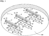
- the support member 2 is attached to a mounting surface 100, such as a ceiling surface, a wall surface, or a floor surface, and the support member 2 supports one or a plurality of types of lighting panels 3 (3a, 3b, and 3c).
- the mounting surface 100 is a ceiling surface, that is, a case where the lighting device 1 is installed in a ceiling. Further, the description below is made for a case where the lighting device 1 includes three of the lighting panels 3a to 3c. The same members among the lighting panels 3a to 3c will be attached with same reference numerals, and omitted from the description. Further, the reference numerals of parts of the lighting panels 3a to 3c are represented by attaching "a", "b” and "c" to the end when components of the lighting panels 3a to 3c are indicated as necessary.
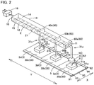
- the lighting device 1 includes the support member 2, a feeding wiring line 25, the lighting panel 3, and a connecting member 5 as shown in Figs. 2 , 3 , 5A, and 5B , and an attaching position of the lighting panel 3 to the support member 2 can be changed.
- the support member 2 is an elongated body extending in a predetermined direction (hereinafter, also referred to as a length direction Y), and as an outline of the support member 2, includes a first end face forming portion 10 constituting one end face in an extending direction Y of the support member 2, a second end face forming portion 11 constituting the other end face, and side face forming portions 12 to 15 connecting sides of the first end face forming portion 10 and the second end face forming portion 11.
- the first end face forming portion 10 is provided with a power source side connecting unit 18 connectable to an external power source or another one of the support member 2.
- the second end face forming portion 11 includes an end face side engagement part 20 (support side engagement part) capable of engaging with a first attaching side engagement part 60a of the lighting panel 3a.
- the end face side engagement part 20 is a fitting hole having a depth in the length direction Y and capable of being fitted to the first attaching side engagement part 60a of the lighting panel 3a, and is also a feed hole capable of feeding power to the lighting panel 3a by being fitted to the first attaching side engagement part 60a.
- a side face forming portion 14 is a top face forming wall portion that constitutes a top face, and can be attached to the mounting surface 100 by an attaching means (not shown).
- the side face forming portion 12 is a bottom surface forming wall portion constituting a bottom surface as shown in Fig. 3 , and includes a plurality of side face side engagement parts 21 (21A to 21L) (support side engagement parts) engageable with first attaching side engagement parts 60b and 60c of the lighting panels 3b and 3c.
- the side face side engagement part 21 is a fitting hole having a depth in a direction orthogonal to the length direction Y and capable of being fitted to the first attaching side engagement parts 60b and 60c of the lighting panels 3b and 3c, and is also a feed hole capable of feeding power to the lighting panels 3b and 3c by being fitted to the first attaching side engagement parts 60b and 60c.
- the engagement parts 20 and 21 both function as a connector with the lighting panel 3 and are not particularly limited as long as they can be engaged with part of the lighting panel 3.
- the engagement parts 20 and 21 are recessed female terminals, and, for example, a USB port and the like can be employed.
- a feeding wiring line 25 connectable to an external power source is incorporated.
- the feeding wiring line 25 is mostly covered by the forming portions 10 to 15 forming an outline of the support member 2.
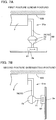
- the feeding wiring line 25 is connected to the engagement parts 20 and 21 at the middle or end, and the engagement parts 20 and 21 are electrically connected in parallel to the power source side connecting unit 18 via the feeding wiring line 25 as shown in Fig. 5B .
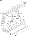
- the lighting panels 3 (3a to 3c) are provided with planar light-emitting panels 30 (30a to 30c) and mounting members 31 (31a to 31c) as main component members as shown in Fig. 3 .
- the planar light-emitting panel 30 is a plate-like panel which spreads in a planar shape and emits light in a plane shape, and is specifically an organic EL panel. That is, the planar light-emitting panel 30 incorporates an organic EL element provided with a light-emitting functional layer including two electrodes facing each other and an organic light-emitting layer sandwiched between two electrodes, and can emit diffused light.
- the planar light-emitting panel 30 is mainly configured with a panel main body 50 incorporating an organic EL element and a panel side engagement part 51, and has the emission surface 55 on one main surface side.
- the panel side engagement part 51 is a panel side power supply portion electrically connected to the organic EL element incorporated in the panel main body 50.
- the panel side engagement part 51 is an engaging piece having an "L" shape in the side view positioned on the other main surface side (the opposite side to the emission surface 55) of the panel main body 50, and includes a vertical wall portion 52 provided to stand from the rear of the panel main body 50, and an insertion part 53 folded from a tip in a standing direction of the vertical wall portion 52.
- the mounting member 31a (second mounting member) is a member for attaching the planar light-emitting panel 30a to the end face side engagement part 20. As shown in Figs. 3 and 4 , the mounting member 31a includes a first attaching side engagement part 60, a second attaching side engagement part 61, and a connecting unit 62 for connecting the first attaching side engagement part 60 and the second attaching side engagement part 61.
- the first attaching side engagement part 60 is a power supply portion that makes a pair with the end face side engagement part 20 or each of the side face side engagement parts 21 (21A to 21L) of the support member 2, and is a fitting piece that can be fitted to any of the engagement parts 20 and 21. That is, by being fitted to the optional engagement parts 20 and 21 arranged in parallel in the extending direction Y, the mounting member 31a can be supplied with power, and can be fixed to the support member 2 at a plurality of places in the extending direction Y.
- the first attaching side engagement part 60 is not particularly limited, as long as it functions as a connector with the support member 2 and can be engaged with part of the support member 2.
- the first attaching side engagement part 60 is a projecting male terminal, and, for example, a USB plug or the like can be employed.
- the second attaching side engagement part 61 includes an insertion port 65 into which the insertion part 53 of the panel side engagement part 51 can be inserted.
- the second attaching side engagement part 61 and the panel side engagement part 51 constitute a push-in/push-out structure, and the panel side engagement part 51 is attachable and detachable. That is, in the lighting device 1, when the insertion part 53 of the panel side engagement part 51 is inserted into the insertion port 65 of the second attaching side engagement part 61 and pushed, the insertion part 53 and the insertion port 65 are engaged and attached, and the panel side engagement part 51 and the second attaching side engagement part 61 are integrated.
- the lighting device 1 when the insertion part 53 is pushed again in an insertion direction to the insertion port 65 in a state where the panel side engagement part 51 is attached to the second attaching side engagement part 61, the engagement of the insertion part 53 and the insertion port 65 is released, and the panel side engagement part 51 can be removed from the second attaching side engagement part 61.
- the connecting unit 62 is provided with a first connecting unit 70, a second connecting unit 71, and a joint part 73 as shown in Fig. 3 .
- the connecting units 70 and 71 are rod-like shaft portions having certain rigidity, and, in principle, are not elastically deformed. As shown in Fig. 5A , the first connecting unit 70 is bent in a middle portion and extends in an "L" shape, and is configured with a support side connecting unit 74 and a joint side connecting unit 75. The second connecting unit 71 extends in a straight line.
- the joint part 73 is a connecting part which rotatably connects the first connecting unit 70 and the second connecting unit 71, and, specifically, is a universal joint. That is, the joint part 73 can freely change an angle at which the joint side connecting unit 75 of the first connecting unit 70 that is rotatable and has two shafts and the second connecting unit 71 intersect.
- the lighting panels 3b and 3c are different from the lighting panel 3a (second lighting panel) in the structure of the mounting members 31b and 31c, and, as shown in Fig. 3 , include the first attaching side engagement part 60, the second attaching side engagement part 61, and a connecting unit 80.
- the connecting unit 80 is a linear portion connecting the first attaching side engagement part 60 and the second attaching side engagement part 61, and has flexibility and bendable.
- a length in a vertical direction (length in a longitudinal direction) of the connecting unit 80 is longer than a length in the vertical direction of the connecting unit 62 (the total length of the joint side connecting unit 75 of the first connecting unit 70 and the second connecting unit 71).
- the connecting member 5 is a flexible sheet-like body made from transparent resin, and, as shown in Figs. 3 and 4 , includes a light-emitting side cover 90, side face side covers 91 and 92, and rear face side covers 93 and 94.
- the light-emitting side cover 90 is a portion covering the emission surface 55 side of a plurality of the planar light-emitting panels 30, has a width similar to that of the planar light-emitting panel 30, and extends in a band shape in the same direction as the support member 2.
- the light-emitting side cover 90 is transparent and can transmit light emitted from the emission surface 55.
- the side face side covers 91 and 92 are portions bent from an end in a width direction X (direction orthogonal to the parallel arrangement direction Y of the lighting panels 3) of the light-emitting side cover 90.
- the rear face side covers 93 and 94 are portions that are folded back from an end in a bending direction of the side face side covers 91 and 92, and are falling prevention pieces that prevent the planar light-emitting panel 30 from falling off.
- the connecting member 5 covers both ends in the width direction X of the lighting panels 3a to 3c and does not cover both ends in the parallel arrangement direction Y. That is, the lighting panels 3a to 3c are movable in the parallel arrangement direction Y (the extending direction of the support member 2).
- planar light-emitting panel 30a (second planar light-emitting panels) and the planar light-emitting panels 30b and 30c are arranged in a straight line, and the connecting member 5 is attached to the planar light-emitting panels 30a to 30c.
- a distance between the planar light-emitting panels 30a to 30c is optional, and may be arranged so that end faces are in contact with each other as shown in Fig. 2 or may be arranged so as to make space between the end faces as shown in Fig. 8 . Further, the planar light-emitting panels 30a to 30c may be arranged at equal intervals, or may be arranged randomly.
- the connecting member 5 extends across the planar light-emitting panels 30a, 30b, and 30c adjacent in the extending direction Y of the support member 2, and the planar light-emitting panels 30a, 30b, and 30c are aligned in a straight line at equal intervals.
- the insertion part 53 of the panel side engagement part 51 of each of the planar light-emitting panels 30a to 30c is inserted into the insertion port 65 of the second attaching side engagement part 61 of each of the mounting members 31a to 31c. That is, the insertion part 53 is inserted into the insertion port 65 in a spreading direction of the emission surface 55 of the planar light-emitting panels 30a to 30c.
- the insertion directions of the insertion parts 53 of the planar light-emitting panels 30a to 30c into the insertion ports 65 are all the same, and are all in the width directions X of the planar light-emitting panels 30a to 30c (direction orthogonal to the parallel arrangement direction Y when viewed from the front).
- the mounting members 31a to 31c are hidden by the planar light-emitting panels 30a to 30c when viewed from the front.
- the first attaching side engagement part 60a is inserted into the end face side engagement part 20 of the support member 2, and the lighting panels 3a to 3c are fixed to the support member 2.
- the mounting member 31a takes an intersecting posture in which the second connecting unit 71 intersects the joint side connecting unit 75 of the first connecting unit 70 by the joint part 73, and the planar light-emitting panel 30a takes a second posture in which the emission surface 55 is oriented in the same direction as the extending direction Y.
- the lighting panel 3a is supported in a cantilever manner by the support member 2, and the lighting panels 3b and 3c are supported by the lighting panel 3a via the connecting member 5.
- a positional relationship such as the distance between the lighting panels 3a to 3c and the like, is adjusted according to necessity, and, as shown in Fig. 7A , the posture is changed to a linear posture in which the second connecting unit 71 is arranged in the same direction as the joint side connecting unit 75 of the first connecting unit 70 by the joint part 73, and the lighting panel 3a is changed from the second posture to the first posture in which the emission surface 55 of the planar light-emitting panel 30a faces a downward direction, which is orthogonal to the extending direction Y.
- the lighting panels 3b and 3c are rotated in a state of being supported by the lighting panel 3a via the connecting member 5, and the first attaching side engagement parts 60b and 60c are inserted into the side face side engagement parts 21 at optional positions of the support member 2.
- the first attaching side engagement parts 60b and 60c are inserted into the corresponding side face side engagement parts 21 in an upward direction, which is a direction orthogonal to the extending direction of the support member 2, and connecting units 80b and 80c are in a state of being suspended by the support member 2.
- engagement parts between the first attaching side engagement parts 60a to 60b of the mounting members 31 and the engagement parts 20, 21, and 21 of the support member 2 overlap the planar light-emitting panels 30a to 30c when the emission surfaces 55 of the planar light-emitting panels 30a to 30c are viewed from the front.
- the insertion part 53 of the planar light-emitting panel 30b is pulled out from the insertion port 65 of the second attaching side engagement part 61b. That is, the insertion part 53 is pushed into the insertion port 65, the second attaching side engagement part 61b is slid in the width direction X which is an orthogonal direction to the support member 2, engagement between the insertion part 53 and the insertion port 65 is released, and the insertion part 53 is pulled out. Then, as shown in Fig. 9 , in a state where the adjacent planar light-emitting panels 30a and 30c are supported by the support member 2, the connecting member 5 is spread in the width direction X, and the planar light-emitting panel 30b is removed from the connecting member 5.
- the first attaching side engagement part 60b of the lighting panel 3b is moved downward so as to be pulled out from the side face side engagement part 21 of the support member 2, so that engagement between the first attaching side engagement part 60b and the side face side engagement part 21 is released. Then, the connecting member 5 is spread in the width direction X, and the lighting panel 3b is removed from the connecting member 5.
- the planar light-emitting panel 30 can be moved in the extending direction Y of the connecting member 5 in a state of being attached to the connecting member 5, and the planar light-emitting panel 30 can be disposed at a desired position in the extending direction of the support member 2.
- the lighting panel 3 can be installed at a desired position by inserting the first attaching side engagement part 60 into the side face side engagement part 21 that matches with a desired arrangement position.
- an insertion direction of the first attaching side engagement part 60 into the side face side engagement part 21 is orthogonal to the extending direction of the support member 2, and, furthermore, an insertion direction of the insertion part 53 into the insertion port 65 on a projection plane in a thickness direction of the planar light-emitting panel 30 is also orthogonal to the extending direction of the support member 2.
- the first attaching side engagement part 60 is inserted into the side face side engagement part 21, and the insertion part 53 is inserted into the insertion port 65, it is not buffered by the other lighting panel 3 arranged in parallel in the extending direction, and attaching and detaching work is facilitated.
- the mounting member 31 since the mounting member 31 is hidden by the planar light-emitting panel 30 when viewed from the front, the mounting member 31 is difficult to visually recognize from the user side, and the appearance is better than that in the prior art.
- the connecting member 5 has flexibility. Accordingly, as shown in Fig. 9 , by spreading the connecting member 5 outward to form space between the connecting member 5 and the planar light-emitting panel 30, the planar light-emitting panel 30 can be removed from the space while being supported by the support member 2.
- the lighting device 1 of the present embodiment since a large part of the feeding wiring line 25 is covered by the forming portions 10 to 15 of the support member 2, the user can be prevented from directly touching the feeding wiring line 25.
- the emission surface 55 of each of the lighting panels 3a to 3c has height adjusted by the connecting member 5, and can be visually recognized through the light-emitting side cover 90 of the connecting member 5. For this reason, the lighting device 1 can be recognized by the user as a series of one illumination.
- the planar light-emitting panels 30a to 30c used for the lighting panels 3a to 3c are the same type. For this reason, the yield is improved as compared with a case where different types of the planar light-emitting panels 30 are used individually, and the lighting device 1 can be manufactured at a lower cost as compared with the prior art. Note that, the lighting device 1 may use different types of the planar light-emitting panels 30 individually when needed.
- the support member 2 is provided with a plurality of the side face side engagement parts 21, and, by changing the side face side engagement part 21 to be engaged with the first attaching side engagement part 60, the position of the lighting panel 3 relative to the support member 2 can be adjusted. For this reason, position adjustment of the lighting panel 3 is easy.
- the lighting device 200 includes a lighting panel 201, a rail member 202 (support member), a first wiring member 203 (feeding wiring line), and a second wiring member 204 (feeding wiring line).
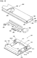
- the lighting panel 201 is equipped with a planar light-emitting panel 210 and a mounting member 211 as shown in Fig. 13 .
- the planar light-emitting panel 210 is an organic EL panel having the emission surface 55 on the front, and has a raised portion 215 on the rear.
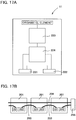
- the raised portion 215 is a projecting portion raised in a thickness direction of the planar light-emitting panel 210 with respect to the other rear surface portion, and is a protection portion for storing and protecting a constant current element 223 and a control switching portion 224 shown in Fig. 17A .
- the raised portion 215 has a rectangular shape in a rear view, and has panel side engagement parts 216A and 216B and panel side engagement parts 216C and 216D provided on two opposing sides.
- the panel side engagement parts 216A to 216D are overhanging pieces projecting outward from an end of the raised portion 215 in a spreading direction of the emission surface 55 (hereinafter, also simply referred to as a plane direction), and, as shown in Fig. 13 , configured with a first engagement part 217 which constitutes the same flat and flush surface with the raised portion 215, and a second engagement part 218 which extends from part of the first engagement part 217 in a direction orthogonal to the first engagement part 217.
- the first engagement parts 217 of the panel side engagement parts 216A to 216D are restricting parts that restrict movement of the planar light-emitting panel 210 in a direction orthogonal to the emission surface 55 (overlapping direction with the mounting member 211) by being engaged with holder side engagement parts 240A to 240D of the mounting member 211.
- the second engagement parts 218 of the panel side engagement parts 216A to 216D are restricting parts that restrict movement of the mounting member 211 in the spreading direction (slide movement direction) of the emission surfaces 55 by being engaged with the holder side engagement parts 240A to 240D of the mounting member 211.
- the panel side engagement parts 216A and 216B are provided on one of two sides facing in the extending direction Y of the rail member 202, and are arranged at predetermined intervals along the one side.
- the panel side engagement parts 216C and 216D are provided on the other side, and are arranged along the other side at predetermined intervals.
- the raised portion 215 has a notch 220 that is partially notched when viewed from the rear, and a first connector portion 221 and a second connector portion 222 are provided in the notch 220.
- the connector portions 221 and 222 are power supply connectors that can be connected to wiring side connector portions 280, 281, and 284 of the wiring members 203 and 204.
- the connector portions 221 and 222 are specifically female connectors, and their insertion directions substantially coincide with the plane direction.
- the connector portions 221 and 222 are electrically connected to an organic EL element via the constant current element 223 and the control switching portion 224 which are disposed in the raised portion 215 as shown in Fig. 17A , and are further electrically connected by a conductive path separately without passing through the organic EL element.
- the constant current element 223 is an element capable of supplying a constant current to the organic EL element
- the control switching portion 224 is a portion that switches a plurality of types of control, such as dimming control and toning control, by PWM control or the like.
- the mounting member 211 includes a holder member 230 and engagement units 231A to 231D as shown in Figs. 13 and 15 .
- the holder member 230 includes a holder main body 235 and a holder accommodating portion 236 as shown in Figs. 13 and 14 .
- the holder main body 235 has a holder side opening 239, and includes the holder side engagement parts 240A to 240D and first restriction grooves 244A to 244D along an opening edge of the holder side opening 239.
- the holder side engagement parts 240A to 240D are engaging pieces engageable with the panel side engagement part 216, and, as shown in Fig. 13 , include an extending portion 241 that extends from the holder side opening 239, a vertical wall portion 242 bent from an end of the extending portion 241, and a locking portion 243 further bent from an end of the vertical wall portion 242.
- the first restriction grooves 244A to 244D are grooves for restricting a moving direction of the engagement unit 231, and are substantially "T"-shaped grooves when viewed from the front as shown in Fig. 14 .
- the first restriction grooves 244A to 244D are grooves for locking disengagement of an engaging member 250 from a restricting piece 254, and there exist a portion where the restricting piece 254 can be inserted and removed and a portion where the restricting piece 254 cannot be inserted or removed in an extending direction, and the first restriction grooves 244A to 244D extend in the width direction X as a whole.
- the holder accommodating portion 236 is a casing opened toward the center as shown in Fig. 13 and can accommodate part or all of the engagement unit 231.
- second restriction grooves 245A to 245D are formed on a wall surface on the rear side of the holder accommodating portion.
- the second restriction grooves 245A to 245D are grooves that extend in the width direction X and restrict the moving direction of the engagement unit 231 in the width direction X. As shown in Fig. 16 , the second restriction grooves 245A to 245D are grooves into which a shaft portion 257 of a fixing member 253 can be inserted, and to which a head part 256 of the fixing member 253 is fitted.
- the engagement unit 231 includes the engaging member 250, an urging member 251, and the fixing member 253 as shown in Fig. 16 .
- the engaging member 250 is a fall preventing member which is engaged with the rail member 202 to prevent the lighting panel 201 from falling, and, as shown in Figs. 14 and 16 , includes the restricting piece 254, a locking portion 255, and a fixed portion 258.
- the restricting piece 254 is a locking piece that restricts the moving direction of the engaging member 250 in one direction by moving along the first restriction grooves 244A to 244D.
- the locking portion 255 is an inclined portion which is inclined in a direction intersecting with the insertion direction of the rail member 202.
- the fixed portion 258 is a portion that can be engaged with the fixing member 253, and, specifically, is a fastening hole that can be fastened with the shaft portion 257 of the fixing member 253.
- the urging member 251 is a member that has elasticity and is elastically deformed, so as to urge the engaging member 250 in a predetermined direction, and is specifically a coil spring.
- the urging member 251 is located between the holder accommodating portion 236 and the engaging member 250, and urges the engaging member 250 in a direction away from the holder accommodating portion 236.
- the fixing member 253 has the head part 256 and the shaft portion 257.
- the fixing member 253 is a member that becomes flush with the engaging member 250 when the head part 256 is fitted in the second restriction groove 245, and fixes the engaging member 250 in the holder accommodating portion 236 when the shaft portion 257 passes through the second restriction groove 245 and is engaged with the fixed portion 258 of the engagement unit 231.
- the rail member 202 is fixed to the mounting surface 100 by a fastening element 290 having a head part 291 and a shaft portion 292 as shown in Fig. 18 .
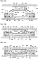
- the rail member 202 is an elongated body having a substantially "H"-shaped cross section as shown in Fig. 12 , and has an outline shape which is preferably a flat shape having a ratio of width to height of 2 or more and 8 or less.
- the rail member 202 includes a first wall portion 260 and a second wall portion 261 facing each other with space between them, and a connecting wall portion 262 that connects middle portions of the wall portions 260 and 261.
- Fixing holes 263 and 264 having different sizes are formed on the first wall portion 260 and the second wall portion 261, and the fixing hole 263 of the first wall portion 260 has an opening that is smaller than the fixing hole 264 of the second wall portion 261.
- the fixing hole 263 of the first wall portion 260 has an opening diameter smaller than an outer diameter of the head part 291 of the fastening element 290 and has an opening diameter larger than an outer diameter of the shaft portion 292.
- the fixing hole 264 of the second wall portion 261 has an opening diameter larger than the outer diameters of the head part 291 and the shaft portion 292 of the fastening element 290.
- the connecting wall portion 262 is a wall portion that is provided in the vicinity of one end of the wall portions 260 and 261, and divides space between the wall portions 260 and 261 into two. That is, the space between the first wall portion 260 and the second wall portion 261 is divided into wiring space 265 in which the wiring members 203 and 204 can be accommodated, and other space 266. Both ends in the width direction X of the second wall portion 261 which is an overhanging portion from the connecting wall portion 262 can be engaged with the engagement unit 231 of the mounting member 211, and constitute rail side engagement parts 270 and 271.
- the first wiring member 203 is provided with the wiring side connector portions 280 and 281, and a wiring portion 282 that connects the wiring side connector portions 280 and 281.
- the second wiring member 204 includes the wiring side connector portion 284 connectable to the connector portions 221 and 222 of the lighting panel 201, an inter-device connection connector portion 285 connectable to the wiring member 204 of another lighting device or an external power source, and a wiring portion 286 that connects the connector portions 284 and 285.
- the wiring side connector portions 280, 281, and 284 are power supply connectors for supplying power to the connector portions 221 and 222 (see Fig. 13 ) of the lighting panel 201, and are, specifically, male connectors.
- the wiring portions 282 and 286 are flexible cord-like portions and bendable.
- the fastening element 290 is inserted from an outer side of the fixing hole 264 of the second wall portion 261 and inserted into the fixing hole 263 of the first wall portion 260 to attach the rail member 202 to the mounting surface 100.
- the shaft portion 292 is inserted into the fixing hole 263, and the head part 291 is positioned in the wiring space 265 between the first wall portion 260 and the second wall portion 261.
- the planar light-emitting panel 210 is inserted into the holder side opening 239 of the mounting member 211, and, in this state, is slid in the width direction X orthogonal to the rail member 202 so as to be attached to the mounting member 211.
- the holder side engagement part 240 of the mounting member 211 is engaged with the panel side engagement part 216 of the planar light-emitting panel 210, and movement of the planar light-emitting panel 210 relative to the mounting member 211 in the sliding direction and overlapping direction is restricted.
- the wiring side connector portion 280 of the first wiring member 203 is inserted into the first connector portion 221.
- the other connector portion 281 of the first wiring member 203 is a free end, and is supported by the first connector portion 221 in a cantilevered manner.
- the wiring members 203 and 204 are pushed into the wiring space 265 of the rail member 202, and the engagement unit 231 of the lighting panel 201 is engaged with the rail side engagement parts 270 and 271 of the rail member 202.
- the rail side engagement parts 270 and 271 abut on the inclined locking portion 255 of the engaging member 250 of the engagement unit 231 and are engaged while expanding the engaging member 250. That is, the rail side engagement parts 270 and 271 move the engaging members 250 away from each other against an urging force of the urging member 251, and, when the rail side engagement parts 270 and 271 move beyond the locking portion 255, an urging force of the urging member 251 moves the engaging members 250 of the engagement unit 231 in the direction of approaching each other.
- the rail side engagement parts 270 and 271 and the engaging member 250 engage in the overlapping direction (the direction orthogonal to the extending direction Y).
- the insertion direction of the wiring side connector portions 280, 281 and 284 of the wiring members 203 and 204 into the first connector portion 221 or the second connector portion 222 is orthogonal to the extending direction Y of the rail member 202.
- the connector portion 221 is electrically connected in series to the connector portion 222 of another lighting panel 201 adjacent in the extending direction Y of the rail member 202 via the first wiring member 203.
- planar light-emitting panel 210 When the planar light-emitting panel 210 is removed from the rail member 202, the planar light-emitting panel 210 is slid in the width direction X orthogonal to the rail member 202, and the planar light-emitting panel 210 is moved to one side in the width direction X. By doing this, the engagement between the panel side engagement parts 216A to 216D of the planar light-emitting panel 210 and the holder side engagement parts 240A to 240D of the mounting member 211 is released, and the planar light-emitting panel 210 is removed from the mounting member 211.
- the mounting member 211 of the lighting panel 201 is moved to one side in the width direction X, and the head part 256 of the fixing member 253 is operated in this state to remove the lighting panel 201 from the rail member 202.
- the mounting member 211 of the lighting panel 201 is slid along the longitudinal direction Y of the rail member 202, and the lighting panel 201 is removed from the end of the rail member 202.
- the respective lighting panels 201 are electrically connected in series, the emission surfaces 55 of the planar light-emitting panels 210 can be evenly lit.
- the lighting device 200 of the present embodiment since the wiring members 203 and 204 are hidden by the rail member 202, the appearance is better than that in the prior art, and disconnection due to external factors, such as contact, does not easily occur.
- the lighting device 300 of the third embodiment is provided with a rail member 301, the support member 2, and lighting panels 3a, 303b, and 303c as shown in Figs. 20 and 21 .
- the rail member 301 includes wall portions 310 and 311 facing each other across accommodating space 316, a connecting wall portion 312 connecting ends of the wall portions 310 and 311, and engagement wall portions 313 and 315 projecting toward an outer side from ends of the wall portions 310 and 311.
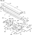
- the lighting panels 303b and 303c are configured with a mounting member 320 and planar light-emitting panels 30b and 30c as shown in Figs. 22 and 23 .
- the mounting member 320 includes engagement units 325A and 325B, a connecting part 326, the first attaching side engagement part 60, the second attaching side engagement part 61, and the connecting unit 80.
- the engagement units 325A and 325B include a skeleton portion 330, engaging members 331A and 331B, urging members 251A and 251B, and fixing members 253A and 253B.
- the skeleton portion 330 includes two accommodating portions 335A and 335B and a connecting unit 336.
- the accommodating portions 335A and 335B are casing-like portions capable of accommodating the engaging members 331A and 331B and the urging members 251A and 251B, and include the second restriction grooves 245A and 245B penetrating in a thickness direction.
- the connecting unit 336 is a portion which connects the accommodating portions 335A and 335B, and is provided with the first restriction grooves 244A and 244B.
- the engaging members 331A and 331B are fall preventing members that are engaged with the rail member 301 to prevent the lighting panels 303b and 303c from falling, and are provided with the restricting piece 254 and the locking portion 255.
- the connecting part 326 is a part which connects the engagement unit 325 and the second attaching side engagement part 61, and is a rod-like body having rigidity.
- the insertion part 53 of the panel side engagement part 51 of each of the planar light-emitting panels 30a to 30c is inserted into the insertion port 65 of the second attaching side engagement part 61 of each of the mounting members 320, and the planar light-emitting panels 30a to 30c are attached to the mounting members 31a, 320b, and 320c.
- the support member 2 is accommodated and fixed in the accommodating space 316 of the rail member 301, and the rail member 301 is fixed to the mounting surface 100 by a fastening element or the like (not shown).
- the insertion part 53 is pushed into the insertion port 65, and the planar light-emitting panel 30b is slid in a direction orthogonal to the support member 2 and pulled out.
- the first attaching side engagement part 60b of the lighting panel 303b is pulled out from the side face side engagement part 21 of the support member 2, and the lighting panel 3a is set to have the second posture.
- the lighting panel 303b is slid in the extending direction of the rail member 301, and the engagement unit 325 is removed from the end of the rail member 301.
- the first attaching side engagement part 60b mainly used for power feeding and the engagement unit 325 used for fixation are separately formed, and the connecting portion of the mounting member 320 and the rail member 301 and the connecting portion of the mounting member 320 and the support member 2 are separate portions. For this reason, even if the mounting member 320 is detached from the rail member 301, the state in which the mounting member 320 and the support member 2 are connected can be maintained, and the fall can be prevented.
- the urging member 251 is provided for each of a plurality of the engagement units 231 (in the case of the second embodiment) facing in the width direction X.
- the present invention is not limited to this configuration.
- the configuration may be such that the urging member 251 is provided only in one of the engagement units 231 facing in the width direction X, and the other engagement units are used simply as locking pieces 360 and 360 (fourth embodiment). That is, the locking pieces 360 and 360 are engaged with the engagement wall portion 313 or the engagement wall portion 315 of the rail member 301, and the engagement unit 231 is pressed against the engagement wall portion 315 or the engagement wall portion 313 of the rail member 301. In this manner, the engagement unit 231 provided with the urging member 251 moves relative to the locking pieces 360 and 360 and is engaged with the engagement wall portion 315 or the engagement wall portion 313.
- the lighting panel 303 is removable from the end of the rail member 301.
- the present invention is not limited to this configuration.
- the configuration may be such that notches 370 and 370 are provided in the engagement wall portions 313 and 315 of the rail member 301, so that the lighting panel 303 can be removed from the notches 370 and 370 (fifth embodiment). That is, by setting the planar light-emitting panel 30a of the lighting panel 3a to be in the second posture and moving the lighting panels 303b and 303c in a longitudinal direction of the rail member 301, the notches 370 and 370 and the engagement units 325A and 325B coincide with each other, and the engagement units 325A and 325B can be removed from the notches 370 and 370.
- the insertion direction of the insertion part 53 into the insertion port 65 and the insertion direction of the wiring side connector portions 280, 281, and 284 into the connector portions 221 and 222 are orthogonal to the extending direction of the support member 2 or the rail member 202.
- the present invention is not limited to this configuration, and the insertion directions may be slightly inclined from the orthogonal direction as long as the directions are substantially orthogonal.
- the insertion direction of the first attaching side engagement parts 60b and 60c into the side face side engagement part 21 and the engaging direction of the rail side engagement parts 270 and 271 and the engaging member 250 are orthogonal to the extending direction of the support member 2 or the rail member 202.
- the present invention is not limited to this configuration, and the directions may be slightly inclined from the orthogonal direction as long as the directions are substantially orthogonal.
- the present invention is not limited to this configuration. Two of the lighting panels 3 may be connected by the connecting member 5, or four or more of the lighting panels 3 may be connected.
- first connecting unit 70 is bent as the connecting unit 62 .
- present invention is not limited to this configuration.
- the first connecting unit 70 may extend linearly as shown in Fig. 28A , or the second connecting unit 71 may be bent in an "L" shape as shown in Fig. 28B . Further, the first connecting unit 70 and the second connecting unit 71 may be curved.
- the connecting unit 62 has a power feeding structure, and power can be fed to the planar light-emitting panel 30a through the joint part 73.
- the present invention is not limited to this configuration. As shown in Fig. 29 , the configuration may be such that a wiring line 350 is provided separately from the connecting unit 62, so that power can be fed to the planar light-emitting panel 30a without the joint part 73.
- the engagement parts 20 and 21 are female terminals, and the first attaching side engagement part 60 is a male terminal.
- the present invention is not limited to this configuration.
- the engagement parts 20 and 21 may be male terminals, and the first attaching side engagement part 60 may be a female terminal.
- the support member 2 and the rail member 202 extend in a straight line.
- the present invention is not limited to this configuration, and the members only need to extend in a predetermined direction as a whole. That is, a portion may be curved, wavy, or zigzag.
- planar light-emitting panels 30 and 210 Although the above-mentioned embodiment describes the case where an organic EL panel is used as the planar light-emitting panels 30 and 210, the present invention is not limited to this configuration.
- the planar light-emitting panels 30 and 210 only need to be one that emits light spread in a plane, and may be, for example, an LED panel in which a plurality of LEDs are scattered in a plane, or an inorganic EL panel.
- the present invention is not limited to this configuration.
- One surface of another structure, such as a desk, may be used as the mounting surface 100.
- the side face forming portion 14 is attached to face or contact the mounting surface 100 which is a ceiling surface.
- the present invention is not limited to this configuration.
- Other side face forming portion 13 or side face forming portion 15 may be attached so as to face or contact the mounting surface 100.
- the engagement parts 20 and 21 are preferably attached so as to face substantially in a horizontal direction.
- the first embodiment above describes the case where the side face side engagement part 21 is provided in the side face forming portion 12 that forms a bottom surface when the mounting surface 100 is attached.
- the side face side engagement part 21 may be provided in the other side face forming portions 13 to 15.
- each component member can be freely replaced or added between the embodiments as long as they are included in the technical scope of the present invention.
Landscapes
- Engineering & Computer Science (AREA)
- General Engineering & Computer Science (AREA)
- Fastening Of Light Sources Or Lamp Holders (AREA)
- Planar Illumination Modules (AREA)
- Arrangement Of Elements, Cooling, Sealing, Or The Like Of Lighting Devices (AREA)
- Non-Portable Lighting Devices Or Systems Thereof (AREA)
Abstract
Description
- The present invention relates to a lighting device and a lighting panel provided with a planar light-emitting panel, such as an organic EL panel, an inorganic EL panel, and an LED panel in which LEDs are spread in a planar shape.
- An organic EL panel is a planar light-emitting panel that emits light in a plane shape, and has a wide lighting range, and, therefore, is used as a lighting device (for example, Patent Document 1). Generally, this organic EL panel has a structure in which an organic EL element is stacked on a substrate such as a glass substrate and sealed, and in which power is supplied to the organic EL element.
- Patent Document 1:
JP 2007-250302 - When an organic EL panel is used as illumination in a somewhat large space, such as a conference room, a plurality of organic EL panels are often used in parallel. In such a case, the organic EL panels are disposed at arbitrary positions. If the organic EL panels are attached in a line without gaps, there is a problem that an adjacent organic EL panel becomes an obstacle at the time of maintenance or replacement of the organic EL panel, and it is difficult to remove the organic EL panel to be replaced.
- In view of the above, an object of the present invention is to provide a lighting device and a lighting panel in which a planar light-emitting panel is supported by a support member, and the planar light-emitting panel can be easily attached to and detached from the support member.
- One aspect of the present invention for solving the above problem is a lighting device, including: a first lighting panel; a support member extending in a predetermined direction; and a feeding wiring line configured to feed power to the first lighting panel, the support member having a support side engagement part, the feeding wiring line being mostly covered with the support member, the first lighting panel including: a planar light-emitting panel having an emission surface; and a mounting member that attaches the planar light-emitting panel to the support member, wherein the planar light-emitting panel is attachable to and detachable from the mounting member, the planar light-emitting panel having a panel side engagement part on a rear surface thereof, wherein the mounting member is fixable to the support member at a plurality of positions in an extending direction of the support member, the mounting member having a first attaching side engagement part and a second attaching side engagement part, wherein the first attaching side engagement part is engageable with the support side engagement part at a position overlapping with the planar light-emitting panel when the emission surface is viewed from front, the first attaching side engagement part being engageable with the support side engagement part in a direction substantially orthogonal to the extending direction of the support member, and wherein the second attaching side engagement part is engageable with or disengageable from the panel side engagement part in the direction substantially orthogonal to the extending direction of the support member.
- The "mostly" used here refers to a portion that occupies 90% or more of the whole.
- The "direction substantially orthogonal to an extending direction" as used here is a direction orthogonal to the extending direction to an extent that it can be almost regarded as a direction orthogonal to the extending direction, and, specifically, a direction that forms an angle with the extending direction at 88 degrees or more and 92 degrees or less.
- According to this aspect, since the part of the feeding wiring line is covered by the support member, it is possible to prevent the occurrence of an electric shock or the like caused by the user touching the feeding wiring line, and the safety is high.
- According to this aspect, the mounting member can be attached to a desired position of the support member, and the planar light-emitting panel can also be installed according to the mounting member.
- According to this aspect, since the fixing direction of the planar light-emitting panel and the fixing direction of the mounting member are both in a relationship of being substantially orthogonal to the extending direction of the support member, adjustment of the fixing position to the support member, and fixation to the support member can be prevented from being buffered.
- According to this aspect, the mounting member is hidden by the planar light-emitting panel because it is engaged at a position overlapping with the planar light-emitting panel when viewed from the front, and the design is better than that of the prior art.
- In a preferable aspect, the support side engagement part is electrically connected to the feeding wiring line, the support side engagement part being fittable to the first attaching side engagement part, and the first lighting panel and the feeding wiring line are electrically connected when the support side engagement part is fitted to the first attaching side engagement part.
- According to this aspect, since the first attaching side engagement part functions as a power supply portion from the support member, attachment of the lighting panel to the support member and power supply from the support member to the lighting panel are facilitated.
- In a preferable aspect, the support member includes two of the support side engagement parts, the two of the support side engagement parts are each electrically connected to the feeding wiring line and are each fittable to the first attaching side engagement part, and the first lighting panel and the feeding wiring line are electrically connected when the first attaching side engagement part is fitted to one of the support side engagement parts.
- According to this aspect, position adjustment is possible by the position of the support side engagement part to which the first attaching side engagement part is fitted.
- In a preferable aspect,
the first attaching side engagement part includes an engagement unit including an engaging piece and an urging member, and when the mounting member is attached to the support member, the engaging piece is urged toward the support member by the urging member, so that the engaging piece is engaged with the support side engagement part. - According to this aspect, since the support side engagement part is engaged by the engaging piece urged by the urging member, the mounting member is less likely to be detached from the support member.
- In a more preferable aspect, the support member includes two of the support side engagement parts, the two of the support side engagement parts including a first and a second support side engagement parts, the mounting member includes two of the engagement units, the two of the engagement units including a first and a second engagement units, the first engagement unit including a first engaging piece and a first urging member, the second engagement unit including a second engaging piece and a second urging member, the first and the second engaging pieces face each other with a space in-between so as to be urged to approach each other by the first and the second urged members respectively, and when the mounting member is attached to the support member, the support member is partially located between the first and the second engagement units while the first and the second support side engagement parts are engaged with the first and the second engaging pieces respectively.
- According to this aspect, since two of the support side engagement parts are engaged with two of the engaging pieces, they are less likely to be detached.
- In a preferable aspect, the lighting device further includes a second lighting panel provided in parallel with and adjacent to the first lighting panel in the extending direction of the support member, wherein the second lighting panel includes a second planar light-emitting panel having an emission surface, and a second mounting member having a first connecting unit and a second connecting unit, wherein the second connecting unit connected to the second planar light-emitting panel is configured to change a posture with respect to the first connecting unit, and wherein the second lighting panel is capable of changing its posture to a first posture and to a second posture by changing a posture of the second connecting unit with respect to the first connecting unit, the first posture being a posture in which the emission surface of the second planar light-emitting panel faces an identical direction to the emission surface of the planar light-emitting panel of the first lighting panel, the second posture being a posture in which the emission surface of the second planar light-emitting panel faces a direction substantially orthogonal to the extending direction.
- According to this aspect, by setting the second lighting panel to the first posture, light can be emitted in the identical direction together with the lighting panel, and by setting the second lighting panel to the second posture, operation space and movement space of the lighting panel at the time of maintenance and the like can be secured.
- A more preferable aspect is that the mounting member of the first lighting panel is movable in the extending direction when the second lighting panel takes the second posture.
- According to this aspect, by setting the second lighting panel to the second posture, a movable range of the lighting panel can be secured, and attaching and detaching of the lighting panel to and from the support member are facilitated.
- In a preferable aspect, the lighting device further includes a second lighting panel provided in parallel with and adjacent to the first lighting panel in the extending direction of the support member, wherein the second lighting panel includes a second planar light-emitting panel having an emission surface, wherein the lighting device further includes a connecting member that performs connection so that the emission surface of the first lighting panel and the emission surface of the second lighting panel are positioned on an identical plane.
- According to this aspect, similar light can be emitted from each lighting panel.
- A more preferable aspect is that the connecting member is formed of a flexible transparent resin, wherein the emission surface of the planar light-emitting panel is at least partially visible through the connecting member, and wherein the planar light-emitting panel is removable from the mounting member by elastically deforming the connecting member.
- According to this aspect, since the connecting member is transparent and flexible, the connecting member can be hardly seen by the user, and by elastically deforming the connecting member, removal of the planar light-emitting panel of the lighting panel is facilitated.
- In a preferable aspect, the support member has a plurality of the support side engagement parts provided at an interval in the predetermined direction, the mounting member has a first attaching side engagement part engageable with each of the plurality of the support side engagement parts, and a position of the first lighting panel with respect to the support member is adjustable by changing the support side engagement part engaged with the first attaching side engagement part.
- According to this aspect, the position adjustment of the lighting panel with respect to the support member can be performed by selecting the support side engagement part with which the first attaching side engagement part is engaged among a plurality of the support side engagement parts. Accordingly, it is easy to dispose the lighting panel at a desired position.
- One aspect of the present invention is a lighting device including: a lighting panel; and a support member extending in a predetermined direction, the support member having a plurality of support side engagement parts provided at an interval in the predetermined direction, the lighting panel including: a planar light-emitting panel having an emission surface; and a mounting member that attaches the planar light-emitting panel to the support member, wherein the planar light-emitting panel is attachable to and detachable from the mounting member, the planar light-emitting having a panel side engagement part on a rear surface thereof, wherein the mounting member includes: a first attaching side engagement part engageable with each of the plurality of support side engagement parts; and a second attaching side engagement part engageable with the panel side engagement part, and wherein a position of the lighting panel with respect to the support member is adjustable by changing the support side engagement part engaged with the first attaching side engagement part.
- According to this aspect, the position adjustment of the lighting panel with respect to the support member can be performed by selecting the support side engagement part with which the first attaching side engagement part is engaged among a plurality of the support side engagement parts. Accordingly, it is easy to dispose the lighting panel at a desired position.
- One aspect of the present invention is a lighting panel supported by a support member that extends in a predetermined direction and that has a support side engagement part, the lighting panel being connectable to a feeding wiring line, the feeding wiring line being mostly covered with the support member, the lighting panel including: a planar light-emitting panel having an emission surface; and a mounting member that attaches the planar light-emitting panel to the support member, wherein the planar light-emitting panel is attachable to and detachable from the mounting member, the planar light-emitting panel having a panel side engagement part on a rear surface thereof, wherein the mounting member is fixable to the support member at a plurality of locations in an extending direction of the support member, the mounting member having a first attaching side engagement part and a second attaching side engagement part, wherein the first attaching side engagement part is engageable with the support side engagement part at a position overlapping with the planar light-emitting panel when the emission surface is viewed from front, the first attaching side engagement part being engageable with the support side engagement part in a direction substantially orthogonal to the extending direction of the support member, and wherein the second attaching side engagement part is engageable with or disengageable from the panel side engagement part in the direction substantially orthogonal to the extending direction of the support member.
- According to this aspect, it is possible to prevent the occurrence of an electric shock or the like due to the user touching the feeding wiring line, and the safety is high. Further, the adjustment of the fixing position to the support member and the fixation to the support member can be prevented from being buffered. Furthermore, since the mounting member is hidden by the planar light-emitting panel, the design is better than in the prior art.
- According to a lighting device and a lighting panel of the present invention, a planar light-emitting panel is supported by a support member, and attachment and detachment of the planar light-emitting panel to and from the support member is easy.
-
-
Fig. 1 is a perspective view schematically showing an installation situation of a lighting device according to a first embodiment of the present invention. -
Fig. 2 is a perspective view of the lighting device ofFig. 1 as viewed from a rear surface side. -
Fig. 3 is an exploded perspective view of the lighting device ofFig. 2 . -
Fig. 4 is an exploded perspective view of the lighting device ofFig. 2 as viewed from a direction different from that ofFig. 3 . -
Figs. 5A and 5B are explanatory views schematically showing a connection relationship between a support member ofFig. 3 and each lighting panel, whereinFig. 5A is a cross-sectional view showing a structural connection relationship between the support member and each lighting panel, andFig. 5B is an electrical circuit diagram showing an electrical connection relationship between the support member and each lighting panel. -
Fig. 6 is an explanatory view showing an example of an assembly process of the lighting device ofFig. 2 , and a perspective view when each planar light-emitting panel in a state of being connected by a connecting member is attached to the support member. -
Figs. 7A and 7B are explanatory views of each posture of the lighting panel ofFig. 2 , whereinFig. 7A is a side view showing a state of a first posture, andFig. 7B is a side view showing a second posture. -
Fig. 8 is a perspective view of the lighting panel in a case where a distance between the planar light-emitting panels of the lighting device ofFig. 2 is increased. -
Fig. 9 is a perspective view showing a situation when the planar light-emitting panel is removed from the connecting member for replacing the lighting device ofFig. 2 . -
Fig. 10 is a perspective view schematically showing an installation situation of a lighting device of a second embodiment of the present invention. -
Fig. 11 is a perspective view of the lighting device ofFig. 10 as viewed from a rear surface side. -
Fig. 12 is an exploded perspective view of the lighting device ofFig. 11 . -
Fig. 13 is an exploded perspective view of a lighting panel ofFig. 12 . -
Fig. 14 is a perspective view of a mounting member ofFig. 13 as viewed from another direction. -
Fig. 15 is a rear view of the lighting panel ofFig. 12 . -
Fig. 16 is an exploded perspective view of a main part of the lighting panel ofFig. 12 . -
Figs. 17A and 17B are explanatory views schematically showing a connection relationship between potions of the lighting device ofFig. 11 , whereinFig. 17A is an electrical circuit diagram showing an electrical connection relationship of a panel main body, andFig. 17B is an electrical circuit diagram showing an electrical connection relationship between the lighting panels. -
Fig. 18 is a perspective view showing a situation when a rail member is attached to a mounting surface. -
Figs. 19A, 19B, and 19C are explanatory views showing a situation when the lighting panel is attached to the rail member, whereinFig. 19A is a cross-sectional view of a main part immediately before the lighting panel is attached to the rail member,Fig. 19B is a cross-sectional view of the main part in the middle of attaching the lighting panel to the rail member, andFig. 19C is a cross-sectional view of the main part in a state where the lighting panel is attached to the rail member. -
Fig. 20 is a perspective view schematically showing an installation situation of the lighting device of a third embodiment of the present invention. -
Fig. 21 is a perspective view of the lighting device ofFig. 20 as viewed from a rear surface side. -
Fig. 22 is an exploded perspective view of the lighting device ofFig. 21 . -
Fig. 23 is an exploded perspective view of the lighting panel ofFig. 22 . -
Figs. 24A, 24B, and 24C are explanatory views showing a situation when the lighting panel is attached to the rail member and the support member, whereinFig. 24A is a cross-sectional view of a main part immediately before the lighting panel is attached to the rail member and the support member,Fig. 24B is a cross-sectional view of the main part in the middle of attaching the lighting panel to the rail member and the support member, andFig. 24C is a cross-sectional view of the main part in a state where the lighting panel is attached to the rail member and the support member. Note that a structure of a wiring line and the like inside the support member is omitted. -
Fig. 25 is a perspective view showing a state in which the lighting panel ofFig. 21 takes a second posture. -
Fig. 26 is a perspective view of the lighting device of a fourth embodiment of the present invention. -
Figs. 27A and 27B are explanatory views of the lighting device of a fifth embodiment of the present invention, whereinFig. 27A is a perspective view when the lighting device functions as a normal illumination in a first posture, andFig. 27B is a perspective view when the mounting member is removed from the rail member in a second posture. -
Figs. 28A and 28B are explanatory views of a main part of a lighting device according to another embodiment of the present invention, whereinFig. 28A is a side view in a case where a first connecting unit is straight, andFig. 28B is a side view in a case where a second connecting unit is bent. -
Fig. 29 is a perspective view of a main part of the lighting device of another embodiment of the present invention. - Hereinafter, embodiments of the present invention will be described in detail. Note that, in the description below, the posture shown in
Fig. 2 is used as a reference unless otherwise noted. Further, anemission surface 55 side is the front, and asupport member 2 side is the rear. - As shown in
Fig. 1 , in alighting device 1 according to the first embodiment of the present invention, thesupport member 2 is attached to a mountingsurface 100, such as a ceiling surface, a wall surface, or a floor surface, and thesupport member 2 supports one or a plurality of types of lighting panels 3 (3a, 3b, and 3c). - The description below is made for a case where the mounting
surface 100 is a ceiling surface, that is, a case where thelighting device 1 is installed in a ceiling. Further, the description below is made for a case where thelighting device 1 includes three of thelighting panels 3a to 3c. The same members among thelighting panels 3a to 3c will be attached with same reference numerals, and omitted from the description. Further, the reference numerals of parts of thelighting panels 3a to 3c are represented by attaching "a", "b" and "c" to the end when components of thelighting panels 3a to 3c are indicated as necessary. - The
lighting device 1 according to the present embodiment includes thesupport member 2, a feedingwiring line 25, thelighting panel 3, and a connectingmember 5 as shown inFigs. 2 ,3 ,5A, and 5B , and an attaching position of thelighting panel 3 to thesupport member 2 can be changed. - As shown in
Figs. 2 and4 , thesupport member 2 is an elongated body extending in a predetermined direction (hereinafter, also referred to as a length direction Y), and as an outline of thesupport member 2, includes a first endface forming portion 10 constituting one end face in an extending direction Y of thesupport member 2, a second endface forming portion 11 constituting the other end face, and side face formingportions 12 to 15 connecting sides of the first endface forming portion 10 and the second endface forming portion 11. - The first end
face forming portion 10 is provided with a power sourceside connecting unit 18 connectable to an external power source or another one of thesupport member 2. - As shown in
Fig. 3 , the second endface forming portion 11 includes an end face side engagement part 20 (support side engagement part) capable of engaging with a first attachingside engagement part 60a of thelighting panel 3a. - The end face
side engagement part 20 is a fitting hole having a depth in the length direction Y and capable of being fitted to the first attachingside engagement part 60a of thelighting panel 3a, and is also a feed hole capable of feeding power to thelighting panel 3a by being fitted to the first attachingside engagement part 60a. - A side
face forming portion 14 is a top face forming wall portion that constitutes a top face, and can be attached to the mountingsurface 100 by an attaching means (not shown). - The side face forming
portion 12 is a bottom surface forming wall portion constituting a bottom surface as shown inFig. 3 , and includes a plurality of side face side engagement parts 21 (21A to 21L) (support side engagement parts) engageable with first attachingside engagement parts lighting panels - The side face
side engagement part 21 is a fitting hole having a depth in a direction orthogonal to the length direction Y and capable of being fitted to the first attachingside engagement parts lighting panels lighting panels side engagement parts - The
engagement parts lighting panel 3 and are not particularly limited as long as they can be engaged with part of thelighting panel 3. In the present embodiment, theengagement parts - In
wiring space 22 surrounded by the formingportions 10 to 15, as shown inFig. 5A , a feedingwiring line 25 connectable to an external power source is incorporated. - The feeding
wiring line 25 is mostly covered by the formingportions 10 to 15 forming an outline of thesupport member 2. The feedingwiring line 25 is connected to theengagement parts engagement parts side connecting unit 18 via thefeeding wiring line 25 as shown inFig. 5B . - The lighting panels 3 (3a to 3c) are provided with planar light-emitting panels 30 (30a to 30c) and mounting members 31 (31a to 31c) as main component members as shown in
Fig. 3 . - The planar light-emitting
panel 30 is a plate-like panel which spreads in a planar shape and emits light in a plane shape, and is specifically an organic EL panel. That is, the planar light-emittingpanel 30 incorporates an organic EL element provided with a light-emitting functional layer including two electrodes facing each other and an organic light-emitting layer sandwiched between two electrodes, and can emit diffused light. - As shown in
Figs. 1 and3 , the planar light-emittingpanel 30 is mainly configured with a panelmain body 50 incorporating an organic EL element and a panelside engagement part 51, and has theemission surface 55 on one main surface side. - The panel
side engagement part 51 is a panel side power supply portion electrically connected to the organic EL element incorporated in the panelmain body 50. As shown inFig. 3 , the panelside engagement part 51 is an engaging piece having an "L" shape in the side view positioned on the other main surface side (the opposite side to the emission surface 55) of the panelmain body 50, and includes avertical wall portion 52 provided to stand from the rear of the panelmain body 50, and aninsertion part 53 folded from a tip in a standing direction of thevertical wall portion 52. - The mounting
member 31a (second mounting member) is a member for attaching the planar light-emittingpanel 30a to the end faceside engagement part 20. As shown inFigs. 3 and4 , the mountingmember 31a includes a first attachingside engagement part 60, a second attachingside engagement part 61, and a connectingunit 62 for connecting the first attachingside engagement part 60 and the second attachingside engagement part 61. - The first attaching
side engagement part 60 is a power supply portion that makes a pair with the end faceside engagement part 20 or each of the side face side engagement parts 21 (21A to 21L) of thesupport member 2, and is a fitting piece that can be fitted to any of theengagement parts optional engagement parts member 31a can be supplied with power, and can be fixed to thesupport member 2 at a plurality of places in the extending direction Y. - The first attaching
side engagement part 60 is not particularly limited, as long as it functions as a connector with thesupport member 2 and can be engaged with part of thesupport member 2. In the present embodiment, the first attachingside engagement part 60 is a projecting male terminal, and, for example, a USB plug or the like can be employed. - As shown in
Fig. 4 , the second attachingside engagement part 61 includes aninsertion port 65 into which theinsertion part 53 of the panelside engagement part 51 can be inserted. - The second attaching
side engagement part 61 and the panelside engagement part 51 constitute a push-in/push-out structure, and the panelside engagement part 51 is attachable and detachable. That is, in thelighting device 1, when theinsertion part 53 of the panelside engagement part 51 is inserted into theinsertion port 65 of the second attachingside engagement part 61 and pushed, theinsertion part 53 and theinsertion port 65 are engaged and attached, and the panelside engagement part 51 and the second attachingside engagement part 61 are integrated. On the other hand, in thelighting device 1, when theinsertion part 53 is pushed again in an insertion direction to theinsertion port 65 in a state where the panelside engagement part 51 is attached to the second attachingside engagement part 61, the engagement of theinsertion part 53 and theinsertion port 65 is released, and the panelside engagement part 51 can be removed from the second attachingside engagement part 61. - The connecting
unit 62 is provided with a first connectingunit 70, a second connectingunit 71, and ajoint part 73 as shown inFig. 3 . - The connecting
units Fig. 5A , the first connectingunit 70 is bent in a middle portion and extends in an "L" shape, and is configured with a supportside connecting unit 74 and a jointside connecting unit 75. The second connectingunit 71 extends in a straight line. - The
joint part 73 is a connecting part which rotatably connects the first connectingunit 70 and the second connectingunit 71, and, specifically, is a universal joint. That is, thejoint part 73 can freely change an angle at which the jointside connecting unit 75 of the first connectingunit 70 that is rotatable and has two shafts and the second connectingunit 71 intersect. - The
lighting panels lighting panel 3a (second lighting panel) in the structure of the mountingmembers Fig. 3 , include the first attachingside engagement part 60, the second attachingside engagement part 61, and a connectingunit 80. - The connecting
unit 80 is a linear portion connecting the first attachingside engagement part 60 and the second attachingside engagement part 61, and has flexibility and bendable. A length in a vertical direction (length in a longitudinal direction) of the connectingunit 80 is longer than a length in the vertical direction of the connecting unit 62 (the total length of the jointside connecting unit 75 of the first connectingunit 70 and the second connecting unit 71). - The connecting
member 5 is a flexible sheet-like body made from transparent resin, and, as shown inFigs. 3 and4 , includes a light-emittingside cover 90, side face side covers 91 and 92, and rear face side covers 93 and 94. - The light-emitting side cover 90 is a portion covering the
emission surface 55 side of a plurality of the planar light-emittingpanels 30, has a width similar to that of the planar light-emittingpanel 30, and extends in a band shape in the same direction as thesupport member 2. The light-emitting side cover 90 is transparent and can transmit light emitted from theemission surface 55. - The side face side covers 91 and 92 are portions bent from an end in a width direction X (direction orthogonal to the parallel arrangement direction Y of the lighting panels 3) of the light-emitting
side cover 90. - The rear face side covers 93 and 94 are portions that are folded back from an end in a bending direction of the side face side covers 91 and 92, and are falling prevention pieces that prevent the planar light-emitting
panel 30 from falling off. - As shown in
Fig. 2 , the connectingmember 5 covers both ends in the width direction X of thelighting panels 3a to 3c and does not cover both ends in the parallel arrangement direction Y. That is, thelighting panels 3a to 3c are movable in the parallel arrangement direction Y (the extending direction of the support member 2). - Then, an assembly procedure of the
lighting device 1 will be described with a positional relationship of each member of thelighting device 1. - First, the planar light-emitting
panel 30a (second planar light-emitting panels) and the planar light-emittingpanels member 5 is attached to the planar light-emittingpanels 30a to 30c. - At this time, a distance between the planar light-emitting
panels 30a to 30c is optional, and may be arranged so that end faces are in contact with each other as shown inFig. 2 or may be arranged so as to make space between the end faces as shown inFig. 8 . Further, the planar light-emittingpanels 30a to 30c may be arranged at equal intervals, or may be arranged randomly. In the present embodiment, the connectingmember 5 extends across the planar light-emittingpanels support member 2, and the planar light-emittingpanels - Further, in a separate process, the
insertion part 53 of the panelside engagement part 51 of each of the planar light-emittingpanels 30a to 30c is inserted into theinsertion port 65 of the second attachingside engagement part 61 of each of the mountingmembers 31a to 31c. That is, theinsertion part 53 is inserted into theinsertion port 65 in a spreading direction of theemission surface 55 of the planar light-emittingpanels 30a to 30c. - At this time, the insertion directions of the
insertion parts 53 of the planar light-emittingpanels 30a to 30c into theinsertion ports 65 are all the same, and are all in the width directions X of the planar light-emittingpanels 30a to 30c (direction orthogonal to the parallel arrangement direction Y when viewed from the front). - Further, engagement parts between the panel
side engagement parts 51 of the planar light-emittingpanels 30a to 30c and the second attachingside engagement parts 61 of the mountingmembers 31a to 31c overlap the planar light-emittingpanels 30a to 30c when the emission surfaces 55 of the planar light-emittingpanels 30a to 30c are viewed from the front. In the present embodiment, the mountingmembers 31a to 31c are hidden by the planar light-emittingpanels 30a to 30c when viewed from the front. - Next, as shown in
Fig. 6 , the first attachingside engagement part 60a is inserted into the end faceside engagement part 20 of thesupport member 2, and thelighting panels 3a to 3c are fixed to thesupport member 2. - At this time, as shown in
Figs. 6 and7B , the mountingmember 31a takes an intersecting posture in which the second connectingunit 71 intersects the jointside connecting unit 75 of the first connectingunit 70 by thejoint part 73, and the planar light-emittingpanel 30a takes a second posture in which theemission surface 55 is oriented in the same direction as the extending direction Y. Thelighting panel 3a is supported in a cantilever manner by thesupport member 2, and thelighting panels lighting panel 3a via the connectingmember 5. - Next, a positional relationship, such as the distance between the
lighting panels 3a to 3c and the like, is adjusted according to necessity, and, as shown inFig. 7A , the posture is changed to a linear posture in which the second connectingunit 71 is arranged in the same direction as the jointside connecting unit 75 of the first connectingunit 70 by thejoint part 73, and thelighting panel 3a is changed from the second posture to the first posture in which theemission surface 55 of the planar light-emittingpanel 30a faces a downward direction, which is orthogonal to the extending direction Y. Then, thelighting panels lighting panel 3a via the connectingmember 5, and the first attachingside engagement parts side engagement parts 21 at optional positions of thesupport member 2. - At this time, the first attaching
side engagement parts side engagement parts 21 in an upward direction, which is a direction orthogonal to the extending direction of thesupport member 2, and connectingunits support member 2. - Further, engagement parts between the first attaching
side engagement parts 60a to 60b of the mounting members 31 and theengagement parts support member 2 overlap the planar light-emittingpanels 30a to 30c when the emission surfaces 55 of the planar light-emittingpanels 30a to 30c are viewed from the front. - Next, in the
lighting device 1 of this embodiment, operation when the planar light-emittingpanel 30b that has been used is replaced will be described. - When the planar light-emitting
panel 30b is removed, theinsertion part 53 of the planar light-emittingpanel 30b is pulled out from theinsertion port 65 of the second attachingside engagement part 61b. That is, theinsertion part 53 is pushed into theinsertion port 65, the second attachingside engagement part 61b is slid in the width direction X which is an orthogonal direction to thesupport member 2, engagement between theinsertion part 53 and theinsertion port 65 is released, and theinsertion part 53 is pulled out. Then, as shown inFig. 9 , in a state where the adjacent planar light-emittingpanels support member 2, the connectingmember 5 is spread in the width direction X, and the planar light-emittingpanel 30b is removed from the connectingmember 5. - Further, in a case of replacing the
entire lighting panel 3b, the first attachingside engagement part 60b of thelighting panel 3b is moved downward so as to be pulled out from the side faceside engagement part 21 of thesupport member 2, so that engagement between the first attachingside engagement part 60b and the side faceside engagement part 21 is released. Then, the connectingmember 5 is spread in the width direction X, and thelighting panel 3b is removed from the connectingmember 5. - According to the
lighting device 1 of the present embodiment, since an end of the connectingmember 5 is open, the planar light-emittingpanel 30 can be moved in the extending direction Y of the connectingmember 5 in a state of being attached to the connectingmember 5, and the planar light-emittingpanel 30 can be disposed at a desired position in the extending direction of thesupport member 2. - According to the
lighting device 1 of the present embodiment, since the first attachingside engagement part 60 can be inserted into and fixed to any of the side faceside engagement parts 21A to 21L, thelighting panel 3 can be installed at a desired position by inserting the first attachingside engagement part 60 into the side faceside engagement part 21 that matches with a desired arrangement position. - According to the
lighting device 1 of the present embodiment, an insertion direction of the first attachingside engagement part 60 into the side faceside engagement part 21 is orthogonal to the extending direction of thesupport member 2, and, furthermore, an insertion direction of theinsertion part 53 into theinsertion port 65 on a projection plane in a thickness direction of the planar light-emittingpanel 30 is also orthogonal to the extending direction of thesupport member 2. For this reason, when the first attachingside engagement part 60 is inserted into the side faceside engagement part 21, and theinsertion part 53 is inserted into theinsertion port 65, it is not buffered by theother lighting panel 3 arranged in parallel in the extending direction, and attaching and detaching work is facilitated. Further, since the mounting member 31 is hidden by the planar light-emittingpanel 30 when viewed from the front, the mounting member 31 is difficult to visually recognize from the user side, and the appearance is better than that in the prior art. - According to the
lighting device 1 of the present embodiment, the connectingmember 5 has flexibility. Accordingly, as shown inFig. 9 , by spreading the connectingmember 5 outward to form space between the connectingmember 5 and the planar light-emittingpanel 30, the planar light-emittingpanel 30 can be removed from the space while being supported by thesupport member 2. - According to the
lighting device 1 of the present embodiment, since a large part of the feedingwiring line 25 is covered by the formingportions 10 to 15 of thesupport member 2, the user can be prevented from directly touching the feedingwiring line 25. - According to the
lighting device 1 of the present embodiment, theemission surface 55 of each of thelighting panels 3a to 3c has height adjusted by the connectingmember 5, and can be visually recognized through the light-emitting side cover 90 of the connectingmember 5. For this reason, thelighting device 1 can be recognized by the user as a series of one illumination. - According to the
lighting device 1 of the present embodiment, the planar light-emittingpanels 30a to 30c used for thelighting panels 3a to 3c are the same type. For this reason, the yield is improved as compared with a case where different types of the planar light-emittingpanels 30 are used individually, and thelighting device 1 can be manufactured at a lower cost as compared with the prior art. Note that, thelighting device 1 may use different types of the planar light-emittingpanels 30 individually when needed. - According to the
lighting device 1 of the present embodiment, thesupport member 2 is provided with a plurality of the side faceside engagement parts 21, and, by changing the side faceside engagement part 21 to be engaged with the first attachingside engagement part 60, the position of thelighting panel 3 relative to thesupport member 2 can be adjusted. For this reason, position adjustment of thelighting panel 3 is easy. - Next, a
lighting device 200 of a second embodiment of the present invention will be described. - As shown in
Figs. 10 to 12 , thelighting device 200 according to the second embodiment of the present invention includes alighting panel 201, a rail member 202 (support member), a first wiring member 203 (feeding wiring line), and a second wiring member 204 (feeding wiring line). - The
lighting panel 201 is equipped with a planar light-emittingpanel 210 and a mountingmember 211 as shown inFig. 13 . - The planar light-emitting
panel 210 is an organic EL panel having theemission surface 55 on the front, and has a raisedportion 215 on the rear. The raisedportion 215 is a projecting portion raised in a thickness direction of the planar light-emittingpanel 210 with respect to the other rear surface portion, and is a protection portion for storing and protecting a constantcurrent element 223 and acontrol switching portion 224 shown inFig. 17A . As shown inFig. 13 , the raisedportion 215 has a rectangular shape in a rear view, and has panelside engagement parts side engagement parts - The panel
side engagement parts 216A to 216D are overhanging pieces projecting outward from an end of the raisedportion 215 in a spreading direction of the emission surface 55 (hereinafter, also simply referred to as a plane direction), and, as shown inFig. 13 , configured with afirst engagement part 217 which constitutes the same flat and flush surface with the raisedportion 215, and asecond engagement part 218 which extends from part of thefirst engagement part 217 in a direction orthogonal to thefirst engagement part 217. - The
first engagement parts 217 of the panelside engagement parts 216A to 216D are restricting parts that restrict movement of the planar light-emittingpanel 210 in a direction orthogonal to the emission surface 55 (overlapping direction with the mounting member 211) by being engaged with holderside engagement parts 240A to 240D of the mountingmember 211. On the other hand, thesecond engagement parts 218 of the panelside engagement parts 216A to 216D are restricting parts that restrict movement of the mountingmember 211 in the spreading direction (slide movement direction) of the emission surfaces 55 by being engaged with the holderside engagement parts 240A to 240D of the mountingmember 211. - The panel
side engagement parts rail member 202, and are arranged at predetermined intervals along the one side. The panelside engagement parts - As shown in
Fig. 13 , the raisedportion 215 has anotch 220 that is partially notched when viewed from the rear, and afirst connector portion 221 and asecond connector portion 222 are provided in thenotch 220. - The
connector portions side connector portions wiring members connector portions - The
connector portions current element 223 and thecontrol switching portion 224 which are disposed in the raisedportion 215 as shown inFig. 17A , and are further electrically connected by a conductive path separately without passing through the organic EL element. - The constant
current element 223 is an element capable of supplying a constant current to the organic EL element, and thecontrol switching portion 224 is a portion that switches a plurality of types of control, such as dimming control and toning control, by PWM control or the like. - The mounting
member 211 includes aholder member 230 andengagement units 231A to 231D as shown inFigs. 13 and15 . - The
holder member 230 includes a holdermain body 235 and aholder accommodating portion 236 as shown inFigs. 13 and14 . The holdermain body 235 has aholder side opening 239, and includes the holderside engagement parts 240A to 240D andfirst restriction grooves 244A to 244D along an opening edge of theholder side opening 239. - The holder
side engagement parts 240A to 240D are engaging pieces engageable with the panel side engagement part 216, and, as shown inFig. 13 , include an extendingportion 241 that extends from theholder side opening 239, a vertical wall portion 242 bent from an end of the extendingportion 241, and a locking portion 243 further bent from an end of the vertical wall portion 242. - The
first restriction grooves 244A to 244D are grooves for restricting a moving direction of theengagement unit 231, and are substantially "T"-shaped grooves when viewed from the front as shown inFig. 14 . Thefirst restriction grooves 244A to 244D are grooves for locking disengagement of an engagingmember 250 from a restrictingpiece 254, and there exist a portion where the restrictingpiece 254 can be inserted and removed and a portion where the restrictingpiece 254 cannot be inserted or removed in an extending direction, and thefirst restriction grooves 244A to 244D extend in the width direction X as a whole. - The holder
accommodating portion 236 is a casing opened toward the center as shown inFig. 13 and can accommodate part or all of theengagement unit 231. In theholder accommodating portion 236,second restriction grooves 245A to 245D are formed on a wall surface on the rear side of the holder accommodating portion. - The
second restriction grooves 245A to 245D are grooves that extend in the width direction X and restrict the moving direction of theengagement unit 231 in the width direction X. As shown inFig. 16 , thesecond restriction grooves 245A to 245D are grooves into which ashaft portion 257 of a fixingmember 253 can be inserted, and to which ahead part 256 of the fixingmember 253 is fitted. - The
engagement unit 231 includes the engagingmember 250, an urgingmember 251, and the fixingmember 253 as shown inFig. 16 . - The engaging
member 250 is a fall preventing member which is engaged with therail member 202 to prevent thelighting panel 201 from falling, and, as shown inFigs. 14 and16 , includes the restrictingpiece 254, a lockingportion 255, and a fixedportion 258. The restrictingpiece 254 is a locking piece that restricts the moving direction of the engagingmember 250 in one direction by moving along thefirst restriction grooves 244A to 244D. The lockingportion 255 is an inclined portion which is inclined in a direction intersecting with the insertion direction of therail member 202. The fixedportion 258 is a portion that can be engaged with the fixingmember 253, and, specifically, is a fastening hole that can be fastened with theshaft portion 257 of the fixingmember 253. - The urging
member 251 is a member that has elasticity and is elastically deformed, so as to urge the engagingmember 250 in a predetermined direction, and is specifically a coil spring. The urgingmember 251 is located between theholder accommodating portion 236 and the engagingmember 250, and urges the engagingmember 250 in a direction away from theholder accommodating portion 236. - The fixing
member 253 has thehead part 256 and theshaft portion 257. - The fixing
member 253 is a member that becomes flush with the engagingmember 250 when thehead part 256 is fitted in thesecond restriction groove 245, and fixes the engagingmember 250 in theholder accommodating portion 236 when theshaft portion 257 passes through thesecond restriction groove 245 and is engaged with the fixedportion 258 of theengagement unit 231. - The
rail member 202 is fixed to the mountingsurface 100 by afastening element 290 having ahead part 291 and ashaft portion 292 as shown inFig. 18 . Therail member 202 is an elongated body having a substantially "H"-shaped cross section as shown inFig. 12 , and has an outline shape which is preferably a flat shape having a ratio of width to height of 2 or more and 8 or less. - The
rail member 202 includes afirst wall portion 260 and asecond wall portion 261 facing each other with space between them, and a connectingwall portion 262 that connects middle portions of thewall portions - Fixing
holes first wall portion 260 and thesecond wall portion 261, and the fixinghole 263 of thefirst wall portion 260 has an opening that is smaller than the fixinghole 264 of thesecond wall portion 261. The fixinghole 263 of thefirst wall portion 260 has an opening diameter smaller than an outer diameter of thehead part 291 of thefastening element 290 and has an opening diameter larger than an outer diameter of theshaft portion 292. The fixinghole 264 of thesecond wall portion 261 has an opening diameter larger than the outer diameters of thehead part 291 and theshaft portion 292 of thefastening element 290. - The connecting
wall portion 262 is a wall portion that is provided in the vicinity of one end of thewall portions wall portions first wall portion 260 and thesecond wall portion 261 is divided intowiring space 265 in which thewiring members other space 266. Both ends in the width direction X of thesecond wall portion 261 which is an overhanging portion from the connectingwall portion 262 can be engaged with theengagement unit 231 of the mountingmember 211, and constitute railside engagement parts - As shown in
Fig. 12 , thefirst wiring member 203 is provided with the wiringside connector portions wiring portion 282 that connects the wiringside connector portions - On the other hand, the
second wiring member 204 includes the wiringside connector portion 284 connectable to theconnector portions lighting panel 201, an inter-deviceconnection connector portion 285 connectable to thewiring member 204 of another lighting device or an external power source, and awiring portion 286 that connects theconnector portions - The wiring
side connector portions connector portions 221 and 222 (seeFig. 13 ) of thelighting panel 201, and are, specifically, male connectors. Thewiring portions - Next, a positional relationship of each member will be described together with an assembly procedure of the
lighting device 200. - First, as shown in
Fig. 18 , thefastening element 290 is inserted from an outer side of the fixinghole 264 of thesecond wall portion 261 and inserted into the fixinghole 263 of thefirst wall portion 260 to attach therail member 202 to the mountingsurface 100.. - At this time, in the
fastening element 290, theshaft portion 292 is inserted into the fixinghole 263, and thehead part 291 is positioned in thewiring space 265 between thefirst wall portion 260 and thesecond wall portion 261. - The planar light-emitting
panel 210 is inserted into theholder side opening 239 of the mountingmember 211, and, in this state, is slid in the width direction X orthogonal to therail member 202 so as to be attached to the mountingmember 211. - At this time, the holder
side engagement part 240 of the mountingmember 211 is engaged with the panel side engagement part 216 of the planar light-emittingpanel 210, and movement of the planar light-emittingpanel 210 relative to the mountingmember 211 in the sliding direction and overlapping direction is restricted. - Next, the wiring
side connector portion 280 of thefirst wiring member 203 is inserted into thefirst connector portion 221. - At this time, the
other connector portion 281 of thefirst wiring member 203 is a free end, and is supported by thefirst connector portion 221 in a cantilevered manner. - Next, the
wiring members wiring space 265 of therail member 202, and theengagement unit 231 of thelighting panel 201 is engaged with the railside engagement parts rail member 202. - At this time, as shown in
Figs. 19A, 19B, and 19C , the railside engagement parts inclined locking portion 255 of the engagingmember 250 of theengagement unit 231 and are engaged while expanding the engagingmember 250. That is, the railside engagement parts members 250 away from each other against an urging force of the urgingmember 251, and, when the railside engagement parts portion 255, an urging force of the urgingmember 251 moves the engagingmembers 250 of theengagement unit 231 in the direction of approaching each other. The railside engagement parts member 250 engage in the overlapping direction (the direction orthogonal to the extending direction Y). - Further, in a state where the
engagement unit 231 is engaged with the railside engagement parts side connector portions wiring members first connector portion 221 or thesecond connector portion 222 is orthogonal to the extending direction Y of therail member 202. - Furthermore, as shown in
Figs. 17A and 17B , in thelighting panel 201, theconnector portion 221 is electrically connected in series to theconnector portion 222 of anotherlighting panel 201 adjacent in the extending direction Y of therail member 202 via thefirst wiring member 203. - When the planar light-emitting
panel 210 is removed from therail member 202, the planar light-emittingpanel 210 is slid in the width direction X orthogonal to therail member 202, and the planar light-emittingpanel 210 is moved to one side in the width direction X. By doing this, the engagement between the panelside engagement parts 216A to 216D of the planar light-emittingpanel 210 and the holderside engagement parts 240A to 240D of the mountingmember 211 is released, and the planar light-emittingpanel 210 is removed from the mountingmember 211. - Further, in a case of replacing the
entire lighting panel 201, the mountingmember 211 of thelighting panel 201 is moved to one side in the width direction X, and thehead part 256 of the fixingmember 253 is operated in this state to remove thelighting panel 201 from therail member 202. Alternatively, the mountingmember 211 of thelighting panel 201 is slid along the longitudinal direction Y of therail member 202, and thelighting panel 201 is removed from the end of therail member 202. - According to the
lighting device 200 of the present embodiment, therespective lighting panels 201 are electrically connected in series, the emission surfaces 55 of the planar light-emittingpanels 210 can be evenly lit. - According to the
lighting device 200 of the present embodiment, since thewiring members rail member 202, the appearance is better than that in the prior art, and disconnection due to external factors, such as contact, does not easily occur. - Next, a
lighting device 300 of a third embodiment will be described. - The
lighting device 300 of the third embodiment is provided with arail member 301, thesupport member 2, andlighting panels Figs. 20 and 21 . - As shown in
Fig. 22 , therail member 301 includeswall portions accommodating space 316, a connectingwall portion 312 connecting ends of thewall portions engagement wall portions wall portions - The
lighting panels member 320 and planar light-emittingpanels Figs. 22 and23 . - The mounting
member 320 includesengagement units part 326, the first attachingside engagement part 60, the second attachingside engagement part 61, and the connectingunit 80. - The
engagement units skeleton portion 330, engagingmembers members members - The
skeleton portion 330 includes twoaccommodating portions unit 336. - The
accommodating portions engaging members members second restriction grooves - The connecting
unit 336 is a portion which connects theaccommodating portions first restriction grooves - The engaging
members rail member 301 to prevent thelighting panels piece 254 and the lockingportion 255. - The connecting
part 326 is a part which connects the engagement unit 325 and the second attachingside engagement part 61, and is a rod-like body having rigidity. - Next, a positional relationship of each member will be described together with an assembly procedure of the
lighting device 300. - First, the
insertion part 53 of the panelside engagement part 51 of each of the planar light-emittingpanels 30a to 30c is inserted into theinsertion port 65 of the second attachingside engagement part 61 of each of the mountingmembers 320, and the planar light-emittingpanels 30a to 30c are attached to the mountingmembers - In a separate process, the
support member 2 is accommodated and fixed in theaccommodating space 316 of therail member 301, and therail member 301 is fixed to the mountingsurface 100 by a fastening element or the like (not shown). - Next, as shown in
Figs. 24A, 24B, and 24C , while the engagingmembers lighting panel 303b (303c) are pressed against theengagement wall portions rail member 301, thelighting panel 303b (303c) is caused to approach therail member 301, so that theengagement wall portions members - At this time, locking
portions members engagement wall portions members engagement wall portions portions members members members members engagement wall portions - When the used planar light-emitting
panel 30b is removed from thelighting device 300, similar to thelighting device 1 of the first embodiment, theinsertion part 53 is pushed into theinsertion port 65, and the planar light-emittingpanel 30b is slid in a direction orthogonal to thesupport member 2 and pulled out. - In a case of replacing the
entire lighting panel 303b, as shown inFig. 25 , the first attachingside engagement part 60b of thelighting panel 303b is pulled out from the side faceside engagement part 21 of thesupport member 2, and thelighting panel 3a is set to have the second posture. In this state, thelighting panel 303b is slid in the extending direction of therail member 301, and the engagement unit 325 is removed from the end of therail member 301. - According to the
lighting device 300 of the third embodiment of the present invention, the first attachingside engagement part 60b mainly used for power feeding and the engagement unit 325 used for fixation are separately formed, and the connecting portion of the mountingmember 320 and therail member 301 and the connecting portion of the mountingmember 320 and thesupport member 2 are separate portions. For this reason, even if the mountingmember 320 is detached from therail member 301, the state in which the mountingmember 320 and thesupport member 2 are connected can be maintained, and the fall can be prevented. - In the second and third embodiments described above, the urging
member 251 is provided for each of a plurality of the engagement units 231 (in the case of the second embodiment) facing in the width direction X. However, the present invention is not limited to this configuration. As shown inFig. 26 , the configuration may be such that the urgingmember 251 is provided only in one of theengagement units 231 facing in the width direction X, and the other engagement units are used simply as lockingpieces 360 and 360 (fourth embodiment). That is, the lockingpieces engagement wall portion 313 or theengagement wall portion 315 of therail member 301, and theengagement unit 231 is pressed against theengagement wall portion 315 or theengagement wall portion 313 of therail member 301. In this manner, theengagement unit 231 provided with the urgingmember 251 moves relative to the lockingpieces engagement wall portion 315 or theengagement wall portion 313. - In the above-described third embodiment, the lighting panel 303 is removable from the end of the
rail member 301. However, the present invention is not limited to this configuration. - As shown in
Figs. 27A and 27B , the configuration may be such thatnotches engagement wall portions rail member 301, so that the lighting panel 303 can be removed from thenotches 370 and 370 (fifth embodiment). That is, by setting the planar light-emittingpanel 30a of thelighting panel 3a to be in the second posture and moving thelighting panels rail member 301, thenotches engagement units engagement units notches - In the embodiment described above, the insertion direction of the
insertion part 53 into theinsertion port 65 and the insertion direction of the wiringside connector portions connector portions support member 2 or therail member 202. However, the present invention is not limited to this configuration, and the insertion directions may be slightly inclined from the orthogonal direction as long as the directions are substantially orthogonal. Similarly, in the embodiment described above, the insertion direction of the first attachingside engagement parts side engagement part 21 and the engaging direction of the railside engagement parts member 250 are orthogonal to the extending direction of thesupport member 2 or therail member 202. However, the present invention is not limited to this configuration, and the directions may be slightly inclined from the orthogonal direction as long as the directions are substantially orthogonal. - In the first embodiment described above, three of the
lighting panels 3a to 3c are connected by the connectingmember 5. However, the present invention is not limited to this configuration. Two of thelighting panels 3 may be connected by the connectingmember 5, or four or more of thelighting panels 3 may be connected. - In the first and third embodiments described above, the case where the first connecting
unit 70 is bent as the connectingunit 62 is described. However, the present invention is not limited to this configuration. The first connectingunit 70 may extend linearly as shown inFig. 28A , or the second connectingunit 71 may be bent in an "L" shape as shown inFig. 28B . Further, the first connectingunit 70 and the second connectingunit 71 may be curved. - In the first and third embodiments described above, the connecting
unit 62 has a power feeding structure, and power can be fed to the planar light-emittingpanel 30a through thejoint part 73. However, the present invention is not limited to this configuration. As shown inFig. 29 , the configuration may be such that awiring line 350 is provided separately from the connectingunit 62, so that power can be fed to the planar light-emittingpanel 30a without thejoint part 73. - In the first and third embodiments described above, the
engagement parts side engagement part 60 is a male terminal. However, the present invention is not limited to this configuration. Theengagement parts side engagement part 60 may be a female terminal. - In the embodiment described above, the
support member 2 and therail member 202 extend in a straight line. However, the present invention is not limited to this configuration, and the members only need to extend in a predetermined direction as a whole. That is, a portion may be curved, wavy, or zigzag. - Although the above-mentioned embodiment describes the case where an organic EL panel is used as the planar light-emitting
panels panels - Although the case where a ceiling surface is used as the mounting
surface 100 is described in the above embodiment, the present invention is not limited to this configuration. One surface of another structure, such as a desk, may be used as the mountingsurface 100. - In the first embodiment described above, the side
face forming portion 14 is attached to face or contact the mountingsurface 100 which is a ceiling surface. However, the present invention is not limited to this configuration. Other side face formingportion 13 or sideface forming portion 15 may be attached so as to face or contact the mountingsurface 100. In these cases, theengagement parts - The first embodiment above describes the case where the side face
side engagement part 21 is provided in the sideface forming portion 12 that forms a bottom surface when the mountingsurface 100 is attached. However, the present invention is not limited to this configuration. The side faceside engagement part 21 may be provided in the other side face formingportions 13 to 15. - In the above-described embodiments, each component member can be freely replaced or added between the embodiments as long as they are included in the technical scope of the present invention.
-
- 1, 200, 300:
- Lighting device
- 2:
- Support member
- 3a, 201, 303a:
- Lighting panel (second lighting panel)
- 3b, 3c, 303b, 303c:
- Lighting panel
- 20:
- End face side engagement part (support side engagement part)
- 21, 21A-21L:
- Side face side engagement part (support side engagement part)
- 22, 265:
- Wiring space
- 25:
- Feeding wiring line
- 30a:
- Planar light-emitting panel (second planar light-emitting panel)
- 30b, 30c, 210:
- Planar light-emitting panel
- 31a:
- Mounting member (second mounting member)
- 31b, 31c:
- Mounting member
- 51:
- Panel side engagement part
- 55:
- Emission surface
- 60:
- First attaching side engagement part
- 61:
- Second attaching side engagement part
- 70:
- First connecting unit
- 71:
- Second connecting unit
- 202:
- Rail member (support member)
- 203:
- First wiring member (feeding wiring line)
- 204:
- Second wiring member (feeding wiring line)
- 211:
- Mounting member
- 217:
- First connecting unit
- 218:
- Second connecting unit
- 231, 231A to 231D, 325, 325A, 325B:
- Engagement unit
- 250, 331, 331A, 331B:
- Engaging member (engaging piece)
- 251, 251A, 251B:
- Urging member
- 270, 271:
- Rail side engagement part (support side engagement part)
- 313, 315:
- Engagement wall portion (support side engagement part)
Claims (12)
- A lighting device, comprising:a first lighting panel;a support member extending in a predetermined direction; anda feeding wiring line configured to feed power to the first lighting panel,the support member having a support side engagement part,the feeding wiring line being mostly covered with the support member,the first lighting panel including:a planar light-emitting panel having an emission surface; anda mounting member that attaches the planar light-emitting panel to the support member,wherein the planar light-emitting panel is attachable to and detachable from the mounting member, the planar light-emitting panel having a panel side engagement part on a rear surface thereof,wherein the mounting member is fixable to the support member at a plurality of positions in an extending direction of the support member, the mounting member having a first attaching side engagement part and a second attaching side engagement part,wherein the first attaching side engagement part is engageable with the support side engagement part at a position overlapping with the planar light-emitting panel when the emission surface is viewed from front, the first attaching side engagement part being engageable with the support side engagement part in a direction substantially orthogonal to the extending direction of the support member, andwherein the second attaching side engagement part is engageable with or disengageable from the panel side engagement part in the direction substantially orthogonal to the extending direction of the support member.
- The lighting device according to claim 1,
wherein the support side engagement part is electrically connected to the feeding wiring line, the support side engagement part being fittable to the first attaching side engagement part, and
wherein the first lighting panel and the feeding wiring line are electrically connected when the support side engagement part is fitted to the first attaching side engagement part. - The lighting device according to claim 1 or 2,
wherein the support member includes two of the support side engagement parts,
wherein the two of the support side engagement parts are each electrically connected to the feeding wiring line and are each fittable to the first attaching side engagement part, and
wherein the first lighting panel and the feeding wiring line are electrically connected when the first attaching side engagement part is fitted to one of the support side engagement parts. - The lighting device according to any one of claims 1 to 3,
wherein the first attaching side engagement part includes an engagement unit including an engaging piece and an urging member, and
wherein when the mounting member is attached to the support member, the engaging piece is urged toward the support member by the urging member, so that the engaging piece is engaged with the support side engagement part. - The lighting device according to claim 4,
wherein the support member includes two of the support side engagement parts,
the two of the support side engagement parts including a first and a second support side engagement parts,
wherein the mounting member includes two of the engagement units,
the two of the engagement units including a first and a second engagement units,
the first engagement unit including a first engaging piece and a first urging member,
the second engagement unit including a second engaging piece and a second urging member,
wherein the first and the second engaging pieces face each other with a space in-between so as to be urged to approach each other by the first and the second urged members respectively, and
wherein when the mounting member is attached to the support member, the support member is partially located between the first and the second engagement units while the first and the second support side engagement parts are engaged with the first and the second engaging pieces respectively. - The lighting device according to any one of claims 1 to 5, further comprising a second lighting panel provided in parallel with and adjacent to the first lighting panel in the extending direction of the support member,
wherein the second lighting panel includes a second planar light-emitting panel having an emission surface, and a second mounting member having a first connecting unit and a second connecting unit,
wherein the second connecting unit connected to the second planar light-emitting panel is configured to change a posture with respect to the first connecting unit, and
wherein the second lighting panel is capable of changing its posture to a first posture and to a second posture by changing a posture of the second connecting unit with respect to the first connecting unit,
the first posture being a posture in which the emission surface of the second planar light-emitting panel faces an identical direction to the emission surface of the planar light-emitting panel of the first lighting panel,
the second posture being a posture in which the emission surface of the second planar light-emitting panel faces a direction substantially orthogonal to the extending direction. - The lighting device according to claim 6, wherein the mounting member of the first lighting panel is movable in the extending direction when the second lighting panel takes the second posture.
- The lighting device according to any one of claims 1 to 7, further comprising a second lighting panel provided in parallel with and adjacent to the first lighting panel in the extending direction of the support member,
wherein the second lighting panel includes a second planar light-emitting panel having an emission surface,
wherein the lighting device further comprises a connecting member that performs connection so that the emission surface of the first lighting panel and the emission surface of the second lighting panel are positioned on an identical plane. - The lighting device according to claim 8,
wherein the connecting member is formed of a flexible transparent resin,
wherein the emission surface of the planar light-emitting panel is at least partially visible through the connecting member, and
wherein the planar light-emitting panel is removable from the mounting member by elastically deforming the connecting member. - The lighting device according to any one of claims 1 to 9,
wherein the support member has a plurality of the support side engagement parts provided at an interval in the predetermined direction,
wherein the mounting member has a first attaching side engagement part engageable with each of the plurality of the support side engagement parts, and
wherein a position of the first lighting panel with respect to the support member is adjustable by changing the support side engagement part engaged with the first attaching side engagement part. - A lighting device comprising:a lighting panel; anda support member extending in a predetermined direction,the support member having a plurality of support side engagement parts provided at an interval in the predetermined direction,the lighting panel including:a planar light-emitting panel having an emission surface; anda mounting member that attaches the planar light-emitting panel to the support member,wherein the planar light-emitting panel is attachable to and detachable from the mounting member, the planar light-emitting having a panel side engagement part on a rear surface thereof,wherein the mounting member includes:a first attaching side engagement part engageable with each of the plurality of support side engagement parts; anda second attaching side engagement part engageable with the panel side engagement part, andwherein a position of the lighting panel with respect to the support member is adjustable by changing the support side engagement part engaged with the first attaching side engagement part.
- A lighting panel supported by a support member that extends in a predetermined direction and that has a support side engagement part, the lighting panel being connectable to a feeding wiring line, the feeding wiring line being mostly covered with the support member,
the lighting panel comprising:a planar light-emitting panel having an emission surface; anda mounting member that attaches the planar light-emitting panel to the support member,wherein the planar light-emitting panel is attachable to and detachable from the mounting member, the planar light-emitting panel having a panel side engagement part on a rear surface thereof,wherein the mounting member is fixable to the support member at a plurality of locations in an extending direction of the support member, the mounting member having a first attaching side engagement part and a second attaching side engagement part,wherein the first attaching side engagement part is engageable with the support side engagement part at a position overlapping with the planar light-emitting panel when the emission surface is viewed from front, the first attaching side engagement part being engageable with the support side engagement part in a direction substantially orthogonal to the extending direction of the support member, andwherein the second attaching side engagement part is engageable with or disengageable from the panel side engagement part in the direction substantially orthogonal to the extending direction of the support member.
Applications Claiming Priority (2)
| Application Number | Priority Date | Filing Date | Title |
|---|---|---|---|
| JP2017097465 | 2017-05-16 | ||
| PCT/JP2017/044790 WO2018211729A1 (en) | 2017-05-16 | 2017-12-13 | Lighting device and lighting panel |
Publications (2)
| Publication Number | Publication Date |
|---|---|
| EP3608584A1 true EP3608584A1 (en) | 2020-02-12 |
| EP3608584A4 EP3608584A4 (en) | 2020-09-16 |
Family
ID=64274208
Family Applications (1)
| Application Number | Title | Priority Date | Filing Date |
|---|---|---|---|
| EP17910002.9A Withdrawn EP3608584A4 (en) | 2017-05-16 | 2017-12-13 | Lighting device and lighting panel |
Country Status (4)
| Country | Link |
|---|---|
| US (1) | US10895371B2 (en) |
| EP (1) | EP3608584A4 (en) |
| JP (1) | JP6995115B2 (en) |
| WO (1) | WO2018211729A1 (en) |
Families Citing this family (1)
| Publication number | Priority date | Publication date | Assignee | Title |
|---|---|---|---|---|
| US11274823B1 (en) | 2016-03-02 | 2022-03-15 | Cooledge Lighting, Inc. | Lighting systems incorporating connections for signal and power transmission |
Family Cites Families (14)
| Publication number | Priority date | Publication date | Assignee | Title |
|---|---|---|---|---|
| US4688869A (en) * | 1985-12-12 | 1987-08-25 | Kelly Steven M | Modular electrical wiring track arrangement |
| US4825540A (en) * | 1985-12-12 | 1989-05-02 | Kelly Steven M | Fabrication of modular electrical wiring tracks |
| US6585529B2 (en) * | 2000-07-28 | 2003-07-01 | Cooper Technologies Company | Connector for track network |
| GB0427835D0 (en) * | 2004-12-20 | 2005-01-19 | Artform Internat Ltd | Product display |
| JP2007250302A (en) | 2006-03-15 | 2007-09-27 | Matsushita Electric Works Ltd | Light emitting panel type lighting apparatus |
| JP2012015075A (en) | 2010-07-05 | 2012-01-19 | Panasonic Electric Works Co Ltd | Electric appliance and appliance mounting member |
| DE202010010444U1 (en) * | 2010-07-21 | 2010-10-14 | Visplay International Ag | Suspension device for displaying goods with a profile rail and a primary carrier which can be suspended therein |
| CN201983038U (en) | 2011-01-24 | 2011-09-21 | 林万炯 | Slide rail lamp |
| US9140436B2 (en) | 2011-05-16 | 2015-09-22 | Abl Ip Holding, Llc | Configurable ceiling lighting system |
| US9062841B2 (en) * | 2012-05-04 | 2015-06-23 | Abl Ip Holding, Llc | Two-dimension configurable lighting system with enhanced light source placement capabilities |
| US8963734B2 (en) * | 2013-02-15 | 2015-02-24 | Mohammad Karaki | Remote controlled pricing information |
| JP6278311B2 (en) | 2014-02-13 | 2018-02-14 | パナソニックIpマネジメント株式会社 | Light emitting module and lighting apparatus using the same |
| WO2016140143A1 (en) | 2015-03-02 | 2016-09-09 | 株式会社キルトプランニングオフィス | Mounting structure of organic el module and organic el module |
| WO2016140144A1 (en) | 2015-03-02 | 2016-09-09 | 株式会社キルトプランニングオフィス | Mounting structure of organic el module and organic el module |
-
2017
- 2017-12-13 WO PCT/JP2017/044790 patent/WO2018211729A1/en not_active Ceased
- 2017-12-13 JP JP2019519045A patent/JP6995115B2/en active Active
- 2017-12-13 EP EP17910002.9A patent/EP3608584A4/en not_active Withdrawn
- 2017-12-13 US US16/606,106 patent/US10895371B2/en active Active
Also Published As
| Publication number | Publication date |
|---|---|
| WO2018211729A1 (en) | 2018-11-22 |
| US10895371B2 (en) | 2021-01-19 |
| US20200149719A1 (en) | 2020-05-14 |
| JPWO2018211729A1 (en) | 2020-03-26 |
| EP3608584A4 (en) | 2020-09-16 |
| JP6995115B2 (en) | 2022-02-04 |
Similar Documents
| Publication | Publication Date | Title |
|---|---|---|
| US11118742B2 (en) | Detachable electrical connection for flat lighting module | |
| US9826579B2 (en) | Illumination system | |
| US9157611B2 (en) | Lighting apparatus having a structure for mounting the lighting arraratus | |
| KR101713054B1 (en) | Line type lighting device | |
| CN103906971B (en) | The holding element of face light lamp for keeping at least one plane, the complete set of equipments and photophore being made of the keeping body of multiple lamp holders and multiple length | |
| CN101641548B (en) | Panel Mount Lighting Components | |
| EP2722584A2 (en) | Lighting apparatus | |
| US9400095B2 (en) | Lighting apparatus | |
| US9200791B2 (en) | Lighting apparatus having rail unit | |
| EP3434971B1 (en) | Illumination device and attachment member | |
| US9423111B2 (en) | Illumination device | |
| US10895371B2 (en) | Lighting device and lighting panel with mounting member, connecting member, and engagement parts | |
| JP6615177B2 (en) | Organic EL module mounting structure and organic EL module | |
| JP2021057268A (en) | Guide light | |
| JP6612843B2 (en) | Organic EL module mounting structure and organic EL module | |
| JP2020087512A (en) | Lighting equipment | |
| JP2020167119A (en) | Lighting equipment | |
| JP2019129094A (en) | Light source unit and lighting device including the same | |
| JP7108950B2 (en) | lighting equipment | |
| JP2020087511A (en) | Lighting equipment | |
| JP2019061831A (en) | Connector and lighting system | |
| KR20150069955A (en) | An led board assembly |
Legal Events
| Date | Code | Title | Description |
|---|---|---|---|
| STAA | Information on the status of an ep patent application or granted ep patent |
Free format text: STATUS: THE INTERNATIONAL PUBLICATION HAS BEEN MADE |
|
| PUAI | Public reference made under article 153(3) epc to a published international application that has entered the european phase |
Free format text: ORIGINAL CODE: 0009012 |
|
| STAA | Information on the status of an ep patent application or granted ep patent |
Free format text: STATUS: REQUEST FOR EXAMINATION WAS MADE |
|
| 17P | Request for examination filed |
Effective date: 20191105 |
|
| AK | Designated contracting states |
Kind code of ref document: A1 Designated state(s): AL AT BE BG CH CY CZ DE DK EE ES FI FR GB GR HR HU IE IS IT LI LT LU LV MC MK MT NL NO PL PT RO RS SE SI SK SM TR |
|
| AX | Request for extension of the european patent |
Extension state: BA ME |
|
| DAV | Request for validation of the european patent (deleted) | ||
| DAX | Request for extension of the european patent (deleted) | ||
| A4 | Supplementary search report drawn up and despatched |
Effective date: 20200813 |
|
| RIC1 | Information provided on ipc code assigned before grant |
Ipc: F21S 8/06 20060101ALI20200807BHEP Ipc: F21S 8/04 20060101AFI20200807BHEP Ipc: F21V 21/35 20060101ALI20200807BHEP Ipc: F21V 21/112 20060101ALI20200807BHEP Ipc: F21V 23/00 20150101ALI20200807BHEP Ipc: F21V 19/00 20060101ALI20200807BHEP Ipc: F21V 21/29 20060101ALI20200807BHEP Ipc: F21V 21/34 20060101ALI20200807BHEP Ipc: H01R 25/16 20060101ALI20200807BHEP Ipc: F21V 23/06 20060101ALI20200807BHEP Ipc: F21Y 105/16 20160101ALN20200807BHEP Ipc: F21Y 115/15 20160101ALI20200807BHEP |
|
| STAA | Information on the status of an ep patent application or granted ep patent |
Free format text: STATUS: THE APPLICATION IS DEEMED TO BE WITHDRAWN |
|
| 18D | Application deemed to be withdrawn |
Effective date: 20210312 |