EP3608583A1 - Lighting device - Google Patents
Lighting device Download PDFInfo
- Publication number
- EP3608583A1 EP3608583A1 EP18781564.2A EP18781564A EP3608583A1 EP 3608583 A1 EP3608583 A1 EP 3608583A1 EP 18781564 A EP18781564 A EP 18781564A EP 3608583 A1 EP3608583 A1 EP 3608583A1
- Authority
- EP
- European Patent Office
- Prior art keywords
- region
- reflector
- light emitting
- optical axis
- focal point
- Prior art date
- Legal status (The legal status is an assumption and is not a legal conclusion. Google has not performed a legal analysis and makes no representation as to the accuracy of the status listed.)
- Withdrawn
Links
Images








Classifications
-
- F—MECHANICAL ENGINEERING; LIGHTING; HEATING; WEAPONS; BLASTING
- F21—LIGHTING
- F21V—FUNCTIONAL FEATURES OR DETAILS OF LIGHTING DEVICES OR SYSTEMS THEREOF; STRUCTURAL COMBINATIONS OF LIGHTING DEVICES WITH OTHER ARTICLES, NOT OTHERWISE PROVIDED FOR
- F21V7/00—Reflectors for light sources
- F21V7/0008—Reflectors for light sources providing for indirect lighting
-
- F—MECHANICAL ENGINEERING; LIGHTING; HEATING; WEAPONS; BLASTING
- F21—LIGHTING
- F21V—FUNCTIONAL FEATURES OR DETAILS OF LIGHTING DEVICES OR SYSTEMS THEREOF; STRUCTURAL COMBINATIONS OF LIGHTING DEVICES WITH OTHER ARTICLES, NOT OTHERWISE PROVIDED FOR
- F21V7/00—Reflectors for light sources
- F21V7/0066—Reflectors for light sources specially adapted to cooperate with point like light sources; specially adapted to cooperate with light sources the shape of which is unspecified
-
- F—MECHANICAL ENGINEERING; LIGHTING; HEATING; WEAPONS; BLASTING
- F21—LIGHTING
- F21V—FUNCTIONAL FEATURES OR DETAILS OF LIGHTING DEVICES OR SYSTEMS THEREOF; STRUCTURAL COMBINATIONS OF LIGHTING DEVICES WITH OTHER ARTICLES, NOT OTHERWISE PROVIDED FOR
- F21V7/00—Reflectors for light sources
- F21V7/0083—Array of reflectors for a cluster of light sources, e.g. arrangement of multiple light sources in one plane
-
- F—MECHANICAL ENGINEERING; LIGHTING; HEATING; WEAPONS; BLASTING
- F21—LIGHTING
- F21V—FUNCTIONAL FEATURES OR DETAILS OF LIGHTING DEVICES OR SYSTEMS THEREOF; STRUCTURAL COMBINATIONS OF LIGHTING DEVICES WITH OTHER ARTICLES, NOT OTHERWISE PROVIDED FOR
- F21V7/00—Reflectors for light sources
- F21V7/04—Optical design
- F21V7/06—Optical design with parabolic curvature
-
- F—MECHANICAL ENGINEERING; LIGHTING; HEATING; WEAPONS; BLASTING
- F21—LIGHTING
- F21W—INDEXING SCHEME ASSOCIATED WITH SUBCLASSES F21K, F21L, F21S and F21V, RELATING TO USES OR APPLICATIONS OF LIGHTING DEVICES OR SYSTEMS
- F21W2131/00—Use or application of lighting devices or systems not provided for in codes F21W2102/00-F21W2121/00
- F21W2131/20—Lighting for medical use
- F21W2131/202—Lighting for medical use for dentistry
-
- F—MECHANICAL ENGINEERING; LIGHTING; HEATING; WEAPONS; BLASTING
- F21—LIGHTING
- F21Y—INDEXING SCHEME ASSOCIATED WITH SUBCLASSES F21K, F21L, F21S and F21V, RELATING TO THE FORM OR THE KIND OF THE LIGHT SOURCES OR OF THE COLOUR OF THE LIGHT EMITTED
- F21Y2103/00—Elongate light sources, e.g. fluorescent tubes
- F21Y2103/10—Elongate light sources, e.g. fluorescent tubes comprising a linear array of point-like light-generating elements
-
- F—MECHANICAL ENGINEERING; LIGHTING; HEATING; WEAPONS; BLASTING
- F21—LIGHTING
- F21Y—INDEXING SCHEME ASSOCIATED WITH SUBCLASSES F21K, F21L, F21S and F21V, RELATING TO THE FORM OR THE KIND OF THE LIGHT SOURCES OR OF THE COLOUR OF THE LIGHT EMITTED
- F21Y2115/00—Light-generating elements of semiconductor light sources
- F21Y2115/10—Light-emitting diodes [LED]
Definitions
- the present embodiment relates to an illumination device capable of illuminating an object with light.
- LED illumination devices that can be used for dental treatment.
- Such an LED illumination device is often configured to secure necessary illuminance by using a plurality of light emitting elements.
- An illumination device of an embodiment includes: a plurality of light emitting elements provided on a surface intersecting with an optical axis; and a plurality of reflectors provided so as to correspond to the plurality of light emitting elements, each of the plurality of reflectors having a curved cross section with at least one focal point, wherein the plurality of reflectors includes: at least one first reflector provided corresponding to a central first region corresponding to the optical axis on the surface intersecting with the optical axis, the at least one first reflector being provided so that one of the plurality of corresponding light emitting elements are positioned within a focal region in the vicinity of the focal point; and at least one second reflector provided corresponding to a second region positioned on the surface intersecting with the optical axis that is deviated from the first region in a direction intersecting with the optical axis, the at least one second reflector having an angular eccentricity so as to collect light on one region on the optical axis and being provided so as to be positioned within a margin
- the illumination device 11 is mainly used for dental treatment, it can naturally be applied to other medical applications or desk lamps.
- the illumination device 11 includes a pair of illumination units 12 (light emitting element array).
- the illumination device 11 includes a support body 13, a lamp shade portion 14 provided in a frame shape so as to be continuous with the support body 13, a transmissive cover 15 provided so as to cover a distal end portion of the lamp shade portion 14 (end portion on the opposite side to an end portion on the support body 13 side), and a pair of illumination units 12 (array of light emitting elements 16) fixed to the support body 13 through leg portions 17 or the like.
- the support body 13 is supported by an arm or the like.
- the support body 13 can be supported at a predetermined position and angle through the arm so as to face a patient.
- the leg portion 17 has, for example, a triangular cross-sectional shape.
- An optical axis 18 (illumination optical axis) of the illumination device 11 as a whole is defined by a set of light irradiated from a plurality of light emitting elements 16 described later.
- the optical axis 18 (illumination optical axis) passes through the center of the support body 13 and coincides with the central axis intersecting with (orthogonal to) the support body 13.
- a surface 21 (light emitting surface) intersecting with the optical axis can be defined in the illumination device 11.
- An example of the surface 21 intersecting with the optical axis can be a surface orthogonal to the optical axis 18, but the present invention is not limited thereto.
- Another example of the surface 21 intersecting with the optical axis may be a surface substantially orthogonal to the optical axis 18.
- the surface 21 intersecting with the optical axis has a first region 21A at the center corresponding to the optical axis 18 and a second region 21B deviating from the first region 21A in a direction intersecting with the optical axis 18.
- an example of the direction intersecting with the optical axis 18 is a horizontal direction (transverse direction), but the present invention is not limited thereto. It is obvious that the direction intersecting with the optical axis 18 may be, for example, a vertical direction (longitudinal direction).
- the illumination unit 12 includes a mirror block 22 having a plurality of reflectors 23 formed thereon, a substrate 24 provided so as to face the mirror block 22 and the plurality of reflectors 23, and a plurality of light emitting elements 16 (light source) provided on a plurality of support portions 25 of the substrate 24 described later.
- the plurality of light emitting elements 16 are linearly provided at substantially constant intervals on the surface 21 (light emitting surface) intersecting with the optical axis, for example, in the direction intersecting with the optical axis 18 (for example, the horizontal direction).
- Each of the plurality of light emitting elements 16 includes, for example, a white LED, but may include LEDs of other colors.
- the colors of some light emitting elements 16 included in the plurality of light emitting elements 16 may be different from the colors of the other light emitting elements 16 included in the plurality of light emitting elements 16.
- the light emitting elements 16 may appropriately use commercially available light emitting elements.
- the substrate 24 includes a printed wiring board made of a glass epoxy resin or the like.
- the substrate 24 is a so-called multilayer substrate formed by laminating a plurality of wiring layers.
- the substrate 24 has an elongated plate shape.
- the substrate 24 may be provided so as to cover the mirror block 22.
- the substrate 24 includes a substrate body 26, a plurality of opening portions 27 provided in the substrate body 26, and a plurality of support portions 25 provided in the substrate body 26.
- the plurality of opening portions 27 is linearly disposed along the extending direction of the substrate 24.
- Each of the plurality of support portions 25 is positioned inside each of the plurality of opening portions 27.
- Each of the plurality of support portions 25 is provided so as to correspond to each of the plurality of reflectors 23.
- the opening portion 27 has a pair of through-hole portions 27A passing through a front surface and a back surface of the substrate 24.
- the pair of through-hole portions 27A is provided on both sides with the support portion 25 interposed therebetween.
- the opening portion 27 has, for example, an approximately octagonal shape, and may have other polygonal shapes.
- the opening portion 27 is provided so as to expose the plurality of reflectors 23 of the mirror block 22 to the outside, which will be described later. Therefore, each of the plurality of opening portions 27 is provided so as to correspond to each of the plurality of reflectors 23.
- each of the plurality of support portions 25 is formed in a bridge shape passing through the opening portion 27.
- the support portion 25 includes a bridge portion 28 and a placement portion 31 provided at the middle of the bridge portion 28.
- One light emitting element 16 is mounted on the placement portion 31.
- the placement portion 31 has, for example, a circular shape and is provided in the middle of the bridge portion 28.
- the light emitting element 16 receives supply of power from a power supply 32 through wirings provided in the bridge portion 28.
- the support portion 25 at the position corresponding to the first region 21A is provided so as to be positioned at the center of the first reflector 23A corresponding thereto, which will be described later.
- the support portion 25 at the position corresponding to the second region 21B is provided so as to be position-deviated in the direction away from the first region 21A with respect to the center of the second reflector 23B corresponding thereto.
- the magnitude of the positional deviation changes according to the position from the first region 21A. More specifically, the magnitude of the positional deviation of the support portion 25 in the direction away from the first region 21A increases as the position of the support portion 25 moves away from the first region 21A (the center of the illumination device 11).
- the magnitude of the positional deviation of the support portion 25 positioned in the vicinity of the first region 21A among the support portions 25 at positions corresponding to the second region 21B is relatively small as compared with that of the center of the second reflector 23B corresponding thereto (positional deviation in the direction away from the first region 21A).
- the magnitude of the positional deviation of the support portion 25 positioned at the position away from the first region 21A among the support portions 25 positioned in the second region 21B is relatively large as compared with that of the center of the second reflector 23B corresponding thereto (positional deviation in the direction away from the first region 21A).
- the mirror block 22 is formed in, for example, an elongated plate shape by a resin material or the like.
- the mirror block 22 includes the plurality of reflectors 23.
- the plurality of reflectors 23 are provided so as to correspond to the plurality of light emitting elements 16.
- the plurality of reflectors 23 are linearly provided at one side of the mirror block 22, for example, at substantially constant intervals.
- Each of the plurality of reflectors 23 is provided in a substantially semispherical shape recessed from one surface.
- the mirror block 22 can be formed by, for example, the following method. Machining (for example, cutting work) is performed from one surface side of a plate material on an elongated plate material made of a resin material to form a semispherical surface on the one surface.
- the plurality of reflectors 23 can be formed on the mirror block 22 by forming a mirror layer on the spherical surface by various thin film forming methods such as vapor deposition or electroless plating.
- the plurality of reflectors 23 includes at least one first reflector 23A and at least one second reflector 23B.
- the at least one first reflector 23A is provided corresponding to the central first region 21A corresponding to the optical axis 18.
- the first reflector 23A is constituted by one piece, but it is obvious that the first reflector 23A may be constituted by a plurality of pieces.
- the first reflector 23A faces the light emitting element 16 positioned in the first region 21A.
- a cross section of the first reflector 23A forms, for example, a curve, and more specifically, forms a quadratic curve.
- a cross section of the curve of the first reflector 23A is, for example, parabolic, but the shape of the cross section of the curve of the first reflector 23A is not limited thereto.
- the cross-sectional shape of the curve of the first reflector 23A may be a shape of a quadratic curve other than a parabola, for example, a hyperbolic shape or an elliptical shape.
- the cross section of the curve of the first reflector 23A is formed by a parabola or a hyperbola, it has one focal point 33.
- the cross section of the curve of the first reflector 23A is formed in an elliptical shape, it has two focal points 33.
- a distance from the apex 34 of the curve to the focal point 33 can be determined mathematically by a known mathematical formula.
- the at least one second reflector 23B is provided corresponding to the second region 21B positioned away from the first region 21A in a direction intersecting with (orthogonal to) the optical axis 18.
- the second reflector 23B is constituted by a plurality of pieces.
- Each of the plurality of second reflectors 23B faces each of the plurality of light emitting elements 16 positioned in the second region 21B.
- Each of the second reflectors 23B has a curved cross section, and the curve has, for example, a quadratic curve shape.
- a cross section of the curve of the second reflector 23B is formed, for example, in a parabolic shape.
- the axis of the curve (parabola) of the second reflector 23B is inclined with respect to the optical axis 18 so as to collect light toward one region 35 (see FIG. 15 ) on the optical axis 18 (illumination optical axis). More specifically, the axis of the curve of the second reflector 23B, that is, the optical axis (individual optical axis 36) of each light emitting element is inclined so as to approach the optical axis 18 (illumination optical axis) as the distance from the illumination device 11 increases.
- the inclination of the axis of the curve of the second reflector 23B is different from the inclination of the axis of the curve of another adjacent second reflector 23B. That is, the inclination of the axis of the curve of the second reflector 23B is larger as the distance from the central first region 21A corresponding to the optical axis 18 increases.
- the shape of the cross section of the curve of the second reflector 23B is not limited to the parabolic shape.
- the shape of the cross section of the curve of the second reflector 23B may be a shape of a quadratic curve other than a parabola, for example, a hyperbolic shape or an elliptical shape.
- a parabola or a hyperbola it has one focal point 33.
- the cross section of the curve of the first reflector 23A is formed in an elliptical shape, it has two focal points 33.
- a distance from the apex 34 of the curve to the focal point 33 can be determined mathematically by a known mathematical formula.
- the inventors attempted to study the arrangement of the plurality of reflectors 23 and the light emitting elements 16, such that an irradiation pattern which remarkably suppressed illuminance could be obtained at a position deviated from the illumination target region 37, while collecting light from the plurality of light emitting elements 16 to obtain sufficient illuminance with respect to the illumination target region 37 around the oral cavity of the patient. It is also required by Japanese Industrial Standards (JIS) (JIS T5753: 2012 dental illuminator) to extremely lower illuminance at a position deviated from the illumination target region 37, especially at the eye position of the patient. In order to reduce the burden on the patient's eyes, the inventors of the present invention conducted intensive studies to realize the illumination device 11 having excellent irradiation pattern cutoff characteristics such that light does not reach the patient's eyes.
- JIS Japanese Industrial Standards
- the inventors first examined at which position of the illumination unit 12 (light emitting element array) the light emitting element 16 most affects the convergence of light of the illumination device 11 as a whole.
- the convergence of light (degree of convergence) is an important parameter to consider so as not to illuminate the position of the patient's eyes. The result is omitted, but in the light emitting element array, the light emitted from the light emitting element 16 and the first reflector 23A positioned at the center did not particularly adversely affect the convergence of light of the entire illumination device 11.
- the reflector 23 was formed with a parabolic surface such that the cross-sectional shape of the reflector 23 became a parabola.
- z 0.025 ⁇ (x 2 + y 2 ) + C was used as the mathematical formula of the parabolic surface of the reflector 23.
- the light emitting element 16 was disposed in the vicinity of the focal point 33 of the parabola of the reflector 23.
- a screen 38 on which light was irradiated was installed at a position 300 mm away from the light emitting element 16 (reflector 23).
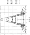
- the examination results are shown in FIG. 8 .
- the horizontal axis Y represents the distance (mm) from the center of light (optical axis 18).
- the vertical axis represents the normalized illuminance.
- the case where the light emitting element 16 is placed at the position of the focal point 33 is set as ⁇ 0.00.
- the case where the light emitting element 16 was moved in the direction away from the reflector 23 in the direction of the optical axis 18 with the focal point 33 set at the reference ( ⁇ 0.00) was set as plus, and the case where the light emitting element 16 was moved in the direction approaching the reflector 23 in the direction of the optical axis 18 was set as minus.
- the position of the light emitting element 16 was moved in the range of 0.10 mm to 1.00 mm. In the direction approaching the reflector 23, the light emitting element 16 was moved in the range of 0.25 mm to 1.0 mm. In this simulation result, the illuminance on the screen 38 when the light emitting element 16 was placed at the focal point 33 was normalized to 1 with respect to the vertical axis.
- the center illuminance when the light emitting element 16 was moved by 1.00 mm from the focal point 33 in the direction away from the reflector 23 in the direction of the optical axis 18 was lower than the center illuminance when the light emitting element 16 was moved by 0.75 mm from the focal point 33 in the direction away from the reflector 23 in the direction of the optical axis 18.
- FIG. 9 illustrates a simulation result when the light emitting element 16 was moved by a distance larger than 1.00 mm from the focal point 33. For example, it was found that when the light emitting element 16 was moved so as to be away from the focal point 33 by 1.50 mm, the center illuminance of the light decreased. Further, it was found that when the light emitting element 16 was moved away from the focal point 33 by 2.00 mm, the center illuminance of the light further decreased and the convergence of light also deteriorated.
- the inventors found that the idea that the blurring (light diffusion) in which the irradiation pattern protruded from the illumination target region 37 could be efficiently reduced was obtained in the light emitting element 16 and the second reflector 23B when the structure for deviating the position of the light emitting element 16 from the focal point 33 as described above was applied with respect to the light emitting element 16 and the second reflector 23B positioned at the position (in the vicinity of the end portion) far from the first region 21A of the array of the light emitting elements 16 (illumination unit 12).
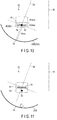
- the margin region 41 means a region having a margin with respect to the convergence of light and is a region in which the convergence and illuminance distribution of the light irradiated from the light emitting element 16 are excellent. Therefore, by deviating the position of the light emitting element 16 from the state illustrated in FIG. 10 to the state illustrated in FIG. 11 and disposing the light emitting element 16 in the margin region 41, it is possible to effectively prevent blurring (light diffusion) in which the irradiation pattern protrudes from the illumination target region 37 irradiated from the light emitting element 16 and the second reflector 23B positioned in the vicinity of the end portion of the light emitting element array.
- the distance from the apex 34 of the curve of the reflector 23 to the focal point 33 of the curve is 10 mm. Therefore, according to the definition of the margin region 41, the inventors set a region between a point moved by a distance of 0.10 mm in the direction away from the second reflector 23B in the direction of the optical axis 18 from the focal point 33 and a point moved by a distance of 1.00 mm in the direction away from the second reflector 23B in the direction of the optical axis 18 from the focal point 33, as the margin region 41 on the actual product.
- a region positioned closer to the focal point 33 than the margin region 41 was set as a second focal region 42.
- the second focal region 42 is slightly deviated from the focal point 33, but is defined as a region having substantially no difference as compared with the case where the light emitting element 16 is disposed at the focal point 33.
- the margin region 41 is provided at a position farther away from the second reflector 23B than the second focal region 42.
- the second focal region 42 is set as a region between a point where a distance equivalent to 0% or more and less than 1% of the distance from the apex 34 of the curve of the second reflector 23B to the focal point 33 is moved in the direction approaching the apex 34 in the direction of the optical axis 18 from the focal point 33 and a point where a distance equivalent to 0% or more and less than 1% of the distance from the apex 34 of the curve of the second reflector 23B to the focal point 33 is moved in the direction away from the apex 34 in the direction of the optical axis 18 from the focal point 33.
- the distance from the apex 34 of the curve of the second reflector 23B to the focal point 33 is 10 mm. Therefore, according to the definition of the second focal region 42, the inventors set a region between a point moved by a distance of less than 0.10 mm in the direction approaching the second reflector 23B in the direction along the optical axis 18 from the focal point 33 and a point moved by a distance of less than 0.10 mm in the direction away from the second reflector 23B in the direction along the optical axis 18 from the focal point 33, as the second focal region 42 on the actual product. In the second reflector 23B and the light emitting element 16 corresponding to the second region 21B, the light emitting element 16 is not actually disposed in the second focal region 42.
- the inventors set a region in the vicinity of the focal point 33 of the curved surface of the first reflector 23A as a focal region 43 even in the light emitting element 16 and the first reflector 23A corresponding to the first region 21A.
- the focal region 43 is slightly deviated from the focal point 33, but is defined as a region having substantially no difference as compared with the case where the light emitting element 16 is disposed at the focal point 33. Since the light emitting element 16 and the first reflector 23A corresponding to the first region 21A are positioned at the center of the array of the light emitting elements 16 (the illumination unit 12), there will be no blurring in which the irradiation pattern protrudes from the illumination target region 37 to the light irradiated therefrom. Therefore, at the position corresponding to the first region 21A, the light emitting element 16 may be disposed at the focal point of the first reflector 23A, or the light emitting element 16 may be disposed in the focal region 43 in the vicinity of the focal point 33.
- the focal region 43 is a region between a point where a distance equivalent to 0% or more and less than 1% of the distance from the apex 34 of the curve of the first reflector 23A to the focal point 33 is moved in the direction approaching the apex 34 in the direction of the optical axis 18 from the focal point 33 and a point where a distance equivalent to 0% or more and less than 1% of the distance from the apex 34 of the curve of the first reflector 23A to the focal point 33 is moved in the direction away from the apex 34 in the direction of the optical axis 18 from the focal point 33.
- the distance from the apex 34 of the curve of the first reflector 23A to the focal point 33 of the curve is 10 mm. Therefore, the inventors set a region between a point moved by a distance of less than 0.10 mm in the direction approaching the first reflector 23A in the direction of the optical axis 18 from the focal point 33 and a point moved by a distance of less than 0.10 mm in the direction away from the first reflector 23A in the direction of the optical axis 18 from the focal point 33, as the focal region 43 on the actual product.
- a region deviated by a predetermined distance from the focal point 33 is set as the margin region 41 and the second focal region 42 in the direction of the optical axis 18 of the entire illumination device 11, but a method of setting the margin region 41 and the second focal region 42 is not limited thereto.
- the margin region 41 and the second focal region 42 may be set in the direction of the optical axis (individual optical axis 36) of the individual light emitting element 16.
- the margin region 41 was set as a region between a point where a distance equivalent to 1% of the distance from the apex 34 of the curve of the second reflector 23B to the focal point 33 was moved in the direction away from the apex 34 in the direction of the individual optical axis 36 from the focal point 33 and a point where a distance equivalent to 10% of the distance from the apex 34 of the curve of the second reflector 23B to the focal point 33 was moved in the direction away from the apex 34 in the direction of the individual optical axis 36 from the focal point 33.
- a distance equivalent to 1% of the distance from the apex 34 of the curve of the second reflector 23B to the focal point 33 was moved in the direction away from the apex 34 in the direction of the individual optical axis 36 from the focal point 33
- a distance equivalent to 10% of the distance from the apex 34 of the curve of the second reflector 23B to the focal point 33 was moved in the direction away from the apex 34 in the direction
- the distance from the apex 34 of the curve of the second reflector 23B to the focal point 33 of the curve is 10 mm. Therefore, the inventors set, as the margin region 41, a region between a point moved by a distance of 0.10 mm in the direction away from the second reflector 23B in the direction of the individual optical axis 36 from the focal point 33 and a point moved by a distance of 1.00 mm in the direction away from the reflector 23 in the direction of the individual optical axis 36 from the focal point 33.
- the second focal region 42 is a region between a point where a distance equivalent to 0% or more and less than 1% of the distance from the apex 34 of the curve of the second reflector 23B to the focal point 33 is moved in the direction approaching the apex 34 in the direction of the individual optical axis 36 from the focal point 33 and a point where a distance equivalent to 0% or more and less than 1% of the distance from the apex 34 of the curve of the second reflector 23B to the focal point 33 is moved in the direction away from the apex 34 in the direction of the individual optical axis 36 from the focal point.
- the distance from the apex 34 of the curve of the second reflector 23B to the focal point 33 of the curve is 10 mm. Therefore, in the present modification, the second focal region 42 is set as region between a point moved by a distance of less than 0.10 mm in the direction approaching the second reflector 23B in the direction of the individual optical axis 36 from the focal point 33 and a point moved by a distance of less than 0.10 mm in the direction away from the second reflector 23B in the direction of the individual optical axis 36 from the focal point 33.
- the position of the light emitting element 16 may be deviated in the direction of the optical axis 18 of the illumination device 11, or the position of the light emitting element 16 may be deviated in the direction of the individual optical axis 36 of the individual light emitting element 16.
- the "direction along the optical axis" in the present specification includes both the direction of the optical axis 18 of the illumination device 11 as a whole and the direction of the optical axis of each of the light emitting elements 16 (the direction of the individual optical axis 36) which is deviated by a predetermined angle from the direction of the optical axis 18, according to the first modification.
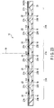
- FIG. 14 illustrates a substrate 24, a light emitting element 16, and a mirror block 22 of an illumination unit 12 of the present embodiment.
- a first reflector 23A and a second reflector 23B formed in the mirror block 22 were formed in a positional relationship as illustrated in FIG. 14 .
- the distance from the apex 34 of the curve of the second reflector 23B to the light emitting element 16 at the position corresponding to the second region 21B is set to be larger as going away from the central first region 21A of the illumination device 11 and approaching the end portion of the illumination unit 12 (array of light emitting elements 16).
- the distance from the apex 34 of the curve of the second reflector 23B in the vicinity of the end portion of the illumination unit 12 to the corresponding light emitting element 16 is larger than the distance from the apex 34 of the curve of the second reflector 23B in the vicinity of the first region 21A to the corresponding light emitting element 16.
- the first reflector 23A corresponding to the center (the first region 21A) of the illumination device 11 was formed so that the light emitting element 16 was positioned within the focal region 43 and the light emitting element 16 had a positional deviation amount of ⁇ 0.0 mm with respect to the focal point 33.
- the first reflector 23A corresponding to the first region 21A may be at any position as long as the position is within the range of the focal region 43 (within a range between a point moved by a distance of less than 0.10 mm in the direction approaching the first reflector 23A in the direction of the optical axis 18 from the focal point 33 and a point moved by a distance of less than 0.10 mm in the direction away from the first reflector 23A in the direction of the optical axis 18 from the focal point 33).
- the second reflector 23B corresponding to the first region 21A side (in the vicinity of the first region 21A) of the second region 21B was formed so that the light emitting element 16 was positioned within the margin region 41 and the light emitting element 16 had a positional deviation amount of +0.2 mm with respect to the focal point 33.
- the apex 34 of the curve of the second reflector 23B is formed at a position that is lower by -0.2 mm than the apex 34 of the curve of the first reflector 23A. Therefore, the light emitting element 16 is disposed at a position deviated by +0.2 mm in the direction away from the second reflector 23B in the direction of the optical axis 18 from the focal point 33.
- the positional deviation amount of the light emitting element 16 with respect to the focal point 33 is an example, and any positional deviation amount may be used as long as the light emitting element 16 is within the margin region 41.
- the positional deviation amount of the light emitting element 16 with respect to the focal point 33 may be, for example, +0.1 mm to +0.2 mm in the direction of the optical axis 18 from the focal point 33 or the direction away from the second reflector 23B in the direction of the individual optical axis 36.
- the second reflector 23B corresponding to the center of the second region 21B was formed so that the light emitting element 16 was positioned within the margin region 41 and the light emitting element 16 had a positional deviation amount of +0.4 mm with respect to the focal point 33.
- the apex 34 of the curve of the second reflector 23B is formed at a position that is lower by -0.4 mm than the apex 34 of the curve of the first reflector 23A. Therefore, the light emitting element 16 is disposed at a position deviated by +0.4 mm in the direction away from the second reflector 23B in the direction of the optical axis 18 from the focal point 33.
- the positional deviation amount of the light emitting element 16 with respect to the focal point 33 is an example, and any positional deviation amount may be used as long as the light emitting element 16 is within the margin region 41.
- the positional deviation amount of the light emitting element 16 with respect to the focal point 33 may be, for example, +0.3 mm to +0.4 mm in the direction of the optical axis 18 from the focal point 33 or the direction away from the second reflector 23B in the direction of the individual optical axis 36.
- the second reflector 23B corresponding to the end portion side (side away from the first region 21A) of the second region 21B was formed so that the light emitting element 16 was positioned within the margin region 41 and the light emitting element 16 had a positional deviation amount of +0.5 mm with respect to the focal point 33.
- the apex 34 of the curve of the second reflector 23B is formed at a position that is lower by -0.5 mm than the apex 34 of the curve of the first reflector 23A. Therefore, the light emitting element 16 is disposed at a position deviated by +0.5 mm in the direction away from the second reflector in the direction of the optical axis 18 from the focal point 33.
- the positional deviation amount of the light emitting element 16 with respect to the focal point 33 is an example, and any positional deviation amount may be used as long as the light emitting element 16 is within the margin region 41.
- the positional deviation amount of the light emitting element 16 with respect to the focal point 33 may be, for example, +0.5 mm to +1.0 mm in the direction of the optical axis 18 from the focal point 33 or the direction away from the second reflector 23B in the direction of the individual optical axis 36.
- FIG. 15 illustrates an aspect in which the second reflector 23B corresponding to the second region 21B is inclined (angular eccentricity) to the axis of the curve toward the end portion side (outer side), and the light irradiated from the light emitting element 16 and the second reflector 23B on the end portion side (outer side) is collected in the direction approaching the optical axis 18 of the entire illumination device 11.
- the light irradiated from the light emitting element 16 and the second reflector 23B corresponding to the second region 21B as described above is collected toward one region 35 on the optical axis 18, and spreads to a predetermined region around one region 35.
- FIGS. 16 and 17 illustrate the results of irradiating the screen 38 with light by using the illumination device of the reference example.
- the light emitting element 16 corresponding thereto is disposed at the position of the focal point 33 of the curve of the first reflector 23A, and the light emitting element 16 corresponding thereto is disposed at the position of the focal point 33 of the curve of the second reflector 23B. Therefore, in the reference example, the position of the light emitting element 16 is not deviated in the direction along the optical axis 18 from the focal point 33 of the curve of the second reflector 23B (the light emitting element 16 is disposed within the margin region 41).
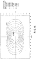
- FIG. 16 illustrates the result when the illuminance distribution (contour) of the light irradiated from the illumination device of the reference example on the screen 38 was set to the maximum value of 60,000 lux (lx).
- the maximum illuminance is determined to be 15,000 lux or more, but in practice, the maximum illuminance needs to be about 60,000 lux.
- the horizontal axis X represents the horizontal direction on the screen 38, and the vertical axis Y represents the vertical direction on the screen 38. From this drawing, it seems that there is no particular problem in the cutoff characteristics at first glance.
- FIG. 16 illustrates the result when the illuminance distribution (contour) of the light irradiated from the illumination device of the reference example on the screen 38 was set to the maximum value of 60,000 lux (lx).
- the maximum illuminance is determined to be 15,000 lux or more, but in practice, the maximum illuminance needs to be about 60,000 lux.
- the horizontal axis X represents the horizontal
- FIG. 17 further illustrates the result when the illuminance distribution (contour) of the light irradiated from the illumination device of the present reference example on the screen 38 was displayed with only the low illuminance range with the maximum value being 1,200 lux. As a result, it was found that the illuminance distribution was disturbed at four corners of the illuminance distribution (position of B-B' line, position of C-C' line).
- FIG. 18 illustrates an A-A' cross section, a B-B' cross section, and a C-C' cross section of the contour in FIG. 17 . It was found from FIG. 18 that any of the A-A' cross section, the B-B' cross section, and the C-C' cross section satisfied the requirement of 1,200 lux or less, which was the reference value specified by the JIS standard (JIS T5753: 2012 dental illuminator), at a position 60 mm or more away from the center of light of the illumination device in the Y axis direction.
- JIS T5753 2012 dental illuminator
- the illumination device of the reference example has room for improvement in cutoff characteristics.
- FIGS. 19 and 20 illustrate the result of irradiating the screen 38 with light by using the illumination device 11 of the present embodiment, that is, the illumination device 11 including the substrate 24, the light emitting element 16, and the mirror block 22 of the illumination unit 12 illustrated in FIG. 14 .
- FIG. 19 illustrates the result when the illuminance distribution (contour) of the light irradiated from the illumination device 11 of the present embodiment on the screen 38 was set to the maximum value of 60,000 lux (lx).
- the horizontal axis X represents the horizontal direction on the screen 38
- the vertical axis Y represents the vertical direction on the screen 38. Also in this drawing, as in the case of the above-described reference example, it seemed that there was no particular problem in the cutoff characteristics.
- FIG. 20 further illustrates the result when the illuminance distribution (contour) of the light irradiated from the illumination device 11 of the present embodiment on the screen 38 was displayed with only the low illuminance range with the maximum value being 1,200 lux.
- the illuminance distribution (contour) of the light irradiated from the illumination device 11 of the present embodiment on the screen 38 was displayed with only the low illuminance range with the maximum value being 1,200 lux.
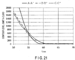
- FIG. 21 illustrates an A-A' cross section, a B-B' cross section, and a C-C' cross section of the contour in FIG. 20 .
- any of the A-A' cross section, the B-B' cross section, and the C-C' cross section satisfied the requirement of 1,200 lux or less, which was the reference value specified by the JIS standard (JIS T5753: 2012 dental illuminator), at a position 60 mm or more away from the center of light of the illumination device 11 in the Y axis direction.
- JIS T5753 2012 dental illuminator
- the illumination device 11 includes a plurality of light emitting elements 16 provided on a surface 21 intersecting with an optical axis, and a plurality of reflectors 23 provided so as to correspond to the plurality of light emitting elements 16, and each of the plurality of reflectors 23 includes a plurality of reflectors 23 having a curved cross section having at least one focal point 33.
- the plurality of reflectors 23 include: at least one first reflector 23A provided corresponding to a central first region 21A corresponding to the optical axis 18 on the surface 21 intersecting with the optical axis, each of the at least one first reflector 23A being providing so as to position one of the plurality of corresponding light emitting elements 16 within a focal region 43 in the vicinity of the focal point 33; and at least one second reflector 23B provided corresponding to a second region 21B positioned on the surface 21 intersecting with an optical axis deviated from the first region 21A in the direction intersecting with the optical axis 18, each of the at least one second reflector 23B having an angular eccentricity so as to collect light on one region 35 on the optical axis 18 and being provided so as to position within a margin region 41 in which one of the plurality of corresponding light emitting elements 16 is provided at a position away from each of the at least one second reflector 23B rather than the second focal region 42 in the vicinity of the focal point 33.
- the at least one second reflector 23B includes one second reflector 23B positioned on the first region 21A side, and the other second reflector 23B provided at a position farther away from the first region 21A than the second reflector 23B.
- a distance from the apex 34 of the curve of the other second reflector 23B to one of the plurality of light emitting elements 16 corresponding to the other second reflector 23B is larger than a distance from the apex 34 of the curve of the one second reflector 23B to one of the plurality of light emitting elements 16 corresponding to the one second reflector 23B.
- the convergence (degree of convergence) of the light irradiated from the light emitting element 16 can be increased at a position away from the first region 21A where the irradiation pattern protrudes from the illumination target region 37, which is likely to cause blurring. Therefore, it is possible to more effectively prevent disturbance of the illuminance distribution caused by the light irradiated from the second reflector 23B and the light emitting element 16 positioned away from the first region 21A.
- the margin region 41 is defined as a region between a point where a distance equivalent to 1% of the distance from the apex 34 of the curve to the focal point 33 is moved in the direction away from the apex 34 in the direction along the optical axis 18 from the focal point 33 and a point where a distance equivalent to 10% of the distance from the apex 34 of the curve to the focal point 33 is moved in the direction away from the apex 34 in the direction along the optical axis 18 from the focal point 33.
- the range where the convergence of the light irradiated from the light emitting element 16 is the most excellent can be set as the margin region 41.
- the focal region 43 and the second focal region 42 are defined as a region between a point where a distance equivalent to 0% or more and less than 1% of the distance from the apex 34 of the curve to the focal point 33 is moved in the direction approaching the apex 34 in the direction along the optical axis 18 from the focal point 33 and a point where a distance equivalent to 0% or more and less than 1% of the distance from the apex 34 of the curve to the focal point 33 is moved in the direction away from the apex 34 in the direction along the optical axis 18 from the focal point 33.
- the position in the vicinity of the focal point 33 can be set as the focal region 43 and the second focal region 42.
- the plurality of light emitting elements 16 are linearly disposed in the direction intersecting with the optical axis 18. In this way, when the light emitting elements 16 are linearly aligned, the distance from the central first region 21A becomes farther toward the end portion of the array of the light emitting elements 16. According to the above configuration, it is possible to efficiently prevent the blurring in which the irradiation pattern protrudes from the illumination target region 37 by the light irradiated from the second reflector 23B and the light emitting element 16 on the end portion side, thereby preventing disturbance of the illuminance distribution when the patient's mouth is irradiated with light.
- Each of the plurality of light emitting elements 16 is an LED. According to this configuration, it is possible to provide the illumination device 11 with energy saving as the whole illumination by adopting an energy-saving LED as the light emitting element 16.
- the illumination device 11 includes a substrate 24 provided so as to face a plurality of reflectors 23, a plurality of opening portions 27 provided in the substrate 24 so as to expose the plurality of reflectors 23, and a plurality of support portions 25 provided on the substrate 24, wherein each of the plurality of support portions 25 includes a plurality of support portions 25 positioned inside each of the plurality of opening portions 27 and supports each of the plurality of light emitting elements 16.
- a structure that supports the light emitting element 16 and also supplies power to the light emitting element 16 can be realized by the substrate 24. Therefore, it is possible to realize the illumination device 11 that can reduce the number of parts and can make the entire structure compact.
- the plurality of light emitting elements 16 are provided on the surface sides of the plurality of support portions 25 that face the plurality of reflectors 23. According to this configuration, it is possible to realize the illumination device 11 that further reduces the burden on the patient, without the situation in which the light from the LED with higher brightness than the other light sources directly enter the patients' eyes.
- Each of the plurality of support portions 25 provided at positions corresponding to the second region 21B is deviated in the direction away from the first region 21A with respect to each center of at least one second reflector 23B corresponding thereto.
- the configuration in which the optical axis (individual optical axis 36) of the individual light emitting element 16 is inclined in the direction approaching the optical axis 18 of the entire illumination device 11 can be realized by a simple structure.
- the magnitude of the positional deviation becomes larger as the distance from the first region 21A increases.
- the configuration in which the inclination of the optical axis (individual optical axis 36) of the individual light emitting element 16 is increased as the distance from the first region 21A increases can be realized by a simple structure.
- the illumination device 11 of the second modification is different from the illumination device 11 of the first embodiment in that a mirror block 22 is divided into each unit for each reflector 23.
- the mirror block 22 is divided into individual blocks 44 corresponding to each reflector 23. Therefore, the distance between an apex 34 of a curve of a second reflector 23B and a focal point 33 can be freely changed. Therefore, for example, the position (height) of the individual block 44 can be finely adjusted by providing a position adjustment knob (screw) on a support body 13 of the illumination device 11. Therefore, the illumination device 11 of the present modification is particularly useful when it is desired to change the convergence (degree of convergence) of light according to the usage situation, and the like.
- the illumination device 11 of the third modification differs from the illumination device 11 of the first embodiment in that the distance between the apex 34 of the curve of the second reflector 23B and the corresponding light emitting element 16 is adjusted by changing the height of the surface of the substrate 24.
- the substrate 24 is constituted by a multilayer substrate and may be configured so that the number of layers constituting the substrate 24 gradually decreases as the distance from the first region 21A increases, and the thickness thereof gradually decreases.
- the substrate 24 may be formed as one stepped substrate by bonding a plurality of substrates in a stepwise fashion while electrically connecting the plurality of substrates, and the height of the surface of the substrate 24 may be gradually lowered.
- the first reflector 23A corresponding to the center (the first region 21A) of the illumination device 11 was formed so that the light emitting element 16 was positioned within the focal region 43 and the light emitting element 16 was formed so as to have a positional deviation amount of ⁇ 0.0 mm with respect to the focal point 33.
- the first reflector 23A corresponding to the first region 21A may be at any position as long as the position is within the range of the focal region 43 (within a range between a point moved by a distance of less than 0.10 mm in the direction approaching the first reflector 23A in the direction of the optical axis 18 from the focal point 33 and a point moved by a distance of less than 0.10 mm in the direction away from the first reflector 23A in the direction of the optical axis 18 from the focal point 33 or in the direction of the individual optical axis 36).
- the second reflector 23B corresponding to the first region 21A side (in the vicinity of the first region 21A) of the second region 21B was formed so that the light emitting element 16 was positioned within the margin region 41 and the light emitting element 16 had a positional deviation amount of +0.2 mm with respect to the focal point 33.
- the light emitting element 16 corresponding to the second reflector 23B was disposed at a position 0.2 mm lower than the height of the light emitting element 16 corresponding to the first reflector 23A (in FIG. 23 , the position 0.2 mm above the light emitting element 16 corresponding to the first reflector 23A).
- the light emitting element 16 is disposed at a position deviated by +0.2 mm in the direction away from the second reflector 23B in the direction of the optical axis 18 from the focal point 33.
- the positional deviation amount of the second reflector 23B corresponding to the first region 21A side of the second region 21B is an example, and the same positional deviation amount as in the first embodiment can be obtained.
- the second reflector 23B corresponding to the center of the second region 21B was formed so that the light emitting element 16 was positioned within the margin region 41 and the light emitting element 16 had a positional deviation amount of +0.4 mm with respect to the focal point 33.
- the light emitting element 16 corresponding to the second reflector 23B was disposed at a position 0.4 mm lower than the height of the light emitting element 16 corresponding to the first reflector 23A (in FIG. 23 , the position 0.4 mm above the light emitting element 16 corresponding to the first reflector 23A). Therefore, the light emitting element 16 is disposed at a position deviated by +0.4 mm in the direction away from the second reflector 23B in the direction of the optical axis 18 from the focal point 33.
- the positional deviation amount of the second reflector 23B corresponding to the center of the second region 21B is an example, and the same positional deviation amount as in the first embodiment can be obtained.
- the second reflector 23B corresponding to the end portion side (side away from the first region 21A) of the second region 21B was formed so that the light emitting element 16 was positioned within the margin region 41 and the light emitting element 16 had a positional deviation amount of +0.5 mm with respect to the focal point 33.
- the light emitting element 16 corresponding to the second reflector 23B was disposed at a position 0.5 mm lower than the height of the light emitting element 16 corresponding to the first reflector 23A (in FIG. 23 , the position 0.5 mm above the light emitting element 16 corresponding to the first reflector 23A).
- the light emitting element 16 is disposed at a position deviated by +0.5 mm in the direction away from the second reflector 23B in the direction of the optical axis 18 from the focal point 33.
- the positional deviation amount of the second reflector 23B corresponding to the end portion side of the second region 21B is an example, and the same positional deviation amount as in the first embodiment can be obtained.
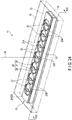
- the second embodiment differs from the first embodiment in that the illumination unit 12 is constituted by one illumination unit.
- the illumination unit 12 is constituted by one illumination unit.
- parts different from those of the first embodiment will be mainly described, and the illustration and explanation of parts common to those of the first embodiment will be omitted.
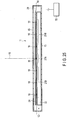
- the illumination device 11 includes a support body 13, a lamp shade portion 14 provided in a frame shape so as to be continuous with the support body 13, a transmissive cover 15 provided so as to cover a distal end portion of the lamp shade portion 14 (end portion on the opposite side to an end portion on the support body 13 side), and one illumination unit 12 (array of light emitting elements 16) fixed to the support body 13.
- the support body 13 is supported by an arm or the like.
- the support body 13 can be supported at a predetermined position and angle through the arm so as to face a patient.
- An optical axis 18 (illumination optical axis) of the illumination device 11 as a whole is defined by a set of light irradiated from a plurality of light emitting elements 16 described later.
- the optical axis 18 passes through the central portion of the support body 13 and coincides with the central axis that intersects (orthogonally) with the support body 13.
- a surface 21 intersecting with the optical axis can be defined in the illumination device 11.
- a surface orthogonal to the optical axis 18 can be mentioned, but is not limited thereto.
- Another example of the surface 21 intersecting with the optical axis may be a surface substantially orthogonal to the optical axis 18.
- the surface 21 intersecting with the optical axis has a first region 21A at the center corresponding to the optical axis 18 and a second region 21B deviating from the first region 21A in a direction intersecting with the optical axis 18.
- an example of the direction intersecting with the optical axis 18 is a horizontal direction (lateral direction), but the present invention is not limited thereto.
- the direction intersecting with the optical axis 18 may be a vertical direction (longitudinal direction).
- the configuration of the illumination unit 12 is the same as that in the first embodiment.
- the plurality of light emitting elements 16 are linearly provided at substantially constant intervals on the surface 21 intersecting with the optical axis in the direction intersecting with the optical axis 18.
- the illuminance of the illumination device 11 is reduced by the small number of the light emitting elements 16, but for example, in addition to the illumination device 11 of the first embodiment, it is particularly useful in the case where it is desired to provide a low-cost low-price illumination device 11 as another product lineup.
Landscapes
- Engineering & Computer Science (AREA)
- General Engineering & Computer Science (AREA)
- Non-Portable Lighting Devices Or Systems Thereof (AREA)
Abstract
Description
- The present embodiment relates to an illumination device capable of illuminating an object with light.
- There are LED illumination devices that can be used for dental treatment. Such an LED illumination device is often configured to secure necessary illuminance by using a plurality of light emitting elements.
-
- PATENT LITERATURE 1: Jpn. Pat. Appln. KOKAI Publication No.
2017-16900 - PATENT LITERATURE 2: Jpn. Pat. Appln. KOKAI Publication No.
2013-211098 - In the case of an illumination device for medical use, improvement is desired not only from user (doctor, dentist) convenience but also from the viewpoint of reducing the burden on patients. There has been a need for an illumination device reducing the burden on patients.
- An illumination device of an embodiment includes: a plurality of light emitting elements provided on a surface intersecting with an optical axis; and a plurality of reflectors provided so as to correspond to the plurality of light emitting elements, each of the plurality of reflectors having a curved cross section with at least one focal point, wherein the plurality of reflectors includes: at least one first reflector provided corresponding to a central first region corresponding to the optical axis on the surface intersecting with the optical axis, the at least one first reflector being provided so that one of the plurality of corresponding light emitting elements are positioned within a focal region in the vicinity of the focal point; and at least one second reflector provided corresponding to a second region positioned on the surface intersecting with the optical axis that is deviated from the first region in a direction intersecting with the optical axis, the at least one second reflector having an angular eccentricity so as to collect light on one region on the optical axis and being provided so as to be positioned within a margin region in which one of the plurality of corresponding light emitting elements are provided at positions farther away than a second focal region in the vicinity of the focal point.
-
-
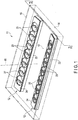
FIG. 1 is a perspective view of an illumination device according to a first embodiment. -
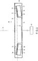
FIG. 2 is a cross-sectional view illustrating the interior of the illumination device by cutting a support body, a lamp shade portion, and a cover along line F2-F2 illustrated inFIG. 1 . -
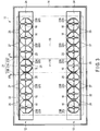
FIG. 3 is a front view of the illumination device illustrated inFIG. 1 . -
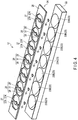
FIG. 4 is an exploded perspective view of one of illumination units of the illumination device illustrated inFIG. 1 . -
FIG. 5 is a cross-sectional view taken along line F5-F5 illustrated inFIG. 3 . -
FIG. 6 is a schematic view schematically illustrating a state of illuminating an oral cavity of a patient with light by using the illumination device of the embodiment. -
FIG. 7 is a schematic diagram illustrating a simulation model using a light emitting element and a parabolic reflector. -
FIG. 8 is a graph illustrating the convergence of light reflected by the parabolic reflector when the position of the light emitting element is deviated in a direction approaching the apex of the paraboloid and a direction away from the apex of the paraboloid with reference to the focal point of the paraboloid by using the model illustrated inFIG. 7 . -
FIG. 9 is a graph illustrating the convergence of light reflected by the parabolic reflector when the position of the light emitting element is deviated in a direction away from the apex of the paraboloid with reference to the focal point of the paraboloid by using the model illustrated inFIG. 7 . -
FIG. 10 is a schematic view illustrating a model of a light emitting element and a second reflector in the vicinity of an end portion of a light emitting element array, in which a margin region is set around a focal point from the results illustrated inFIGS. 8 and9 . -
FIG. 11 is a schematic view illustrating a model of a light emitting element and a second reflector in the vicinity of an end portion of a light emitting element array, in which the position of the light emitting element is deviated in the optical axis direction of the illumination device so as to arrange the light emitting element in the margin region of the schematic view illustrated inFIG. 10 . -
FIG. 12 is a schematic view illustrating a model of a light emitting element and a second reflector in the vicinity of an end portion of a light emitting element array according to a first modification, in which a margin region is set around a focal point from the results illustrated inFIGS. 8 and9 . -
FIG. 13 is a schematic view illustrating a model of a light emitting element and a second reflector in the vicinity of an end portion of a light emitting element array according to the first modification, in which the position of the light emitting element is deviated in the individual optical axis direction of the light emitting element so as to arrange the light emitting element in the margin region of the schematic view illustrated inFIG. 12 . -
FIG. 14 is a cross-sectional view illustrating an illumination unit (a substrate, a light emitting element, and a mirror block) according to the first embodiment. -
FIG. 15 is a schematic view illustrating a model for evaluating the convergence of light by using the illumination unit illustrated inFIG. 14 and schematically illustrating a positional relationship between a screen, a light emitting element, and the like. -
FIG. 16 is a view illustrating an illuminance distribution as a contour line by analyzing the illuminance distribution with a maximum value of 60,000 lux by using an illumination device of a reference example with the same positional relationship as the model illustrated inFIG. 15 . -
FIG. 17 is a view illustrating an illuminance distribution as a contour line by analyzing the illuminance distribution with a maximum value of 1,200 lux by using an illumination device of a reference example with the same positional relationship as the model illustrated inFIG. 15 . -
FIG. 18 is a view illustrating an A-A' cross section, a B-B' cross section, and a C-C' cross section illustrated inFIG. 17 . -
FIG. 19 is a view illustrating an illuminance distribution as a contour line by analyzing the illuminance distribution with a maximum value of 60,000 lux by using the model illustrated inFIG. 15 and using the illumination device of the embodiment arranged as illustrated inFIGS. 1 to 3 by adopting two illumination units illustrated inFIG. 14 . -
FIG. 20 is a view illustrating an illuminance distribution as a contour line by analyzing the illuminance distribution with a maximum value of 1,200 lux by using the model illustrated inFIG. 15 and using the illumination device of the embodiment arranged as illustrated inFIGS. 1 to 3 by adopting two illumination units illustrated inFIG. 14 . -
FIG. 21 is a view illustrating an A-A' cross section, a B-B' cross section, and a C-C' cross section illustrated inFIG. 20 . -
FIG. 22 is a cross-sectional view illustrating an illumination unit (a substrate, a light emitting element, and a mirror block) of an illumination device according to a second modification of the first embodiment. -
FIG. 23 is a cross-sectional view illustrating an illumination unit (a substrate, a light emitting element, and a mirror block) of an illumination device according to a third modification of the first embodiment. -
FIG. 24 is a perspective view illustrating an illumination device according to a second embodiment. -
FIG. 25 is a cross-sectional view illustrating the interior of the illumination device by cutting a support body, a lamp shade portion, and a cover along line F25-F25 illustrated inFIG. 24 . - Hereinafter, a first embodiment of an illumination device will be described with reference to
FIGS. 1 to 21 . Although theillumination device 11 is mainly used for dental treatment, it can naturally be applied to other medical applications or desk lamps. Theillumination device 11 includes a pair of illumination units 12 (light emitting element array). - As illustrated in
FIGS. 1 to 3 , theillumination device 11 includes asupport body 13, alamp shade portion 14 provided in a frame shape so as to be continuous with thesupport body 13, atransmissive cover 15 provided so as to cover a distal end portion of the lamp shade portion 14 (end portion on the opposite side to an end portion on thesupport body 13 side), and a pair of illumination units 12 (array of light emitting elements 16) fixed to thesupport body 13 throughleg portions 17 or the like. Thesupport body 13 is supported by an arm or the like. For example, thesupport body 13 can be supported at a predetermined position and angle through the arm so as to face a patient. Theleg portion 17 has, for example, a triangular cross-sectional shape. An optical axis 18 (illumination optical axis) of theillumination device 11 as a whole is defined by a set of light irradiated from a plurality oflight emitting elements 16 described later. The optical axis 18 (illumination optical axis) passes through the center of thesupport body 13 and coincides with the central axis intersecting with (orthogonal to) thesupport body 13. - Further, as illustrated in
FIGS. 2 and3 , a surface 21 (light emitting surface) intersecting with the optical axis can be defined in theillumination device 11. An example of thesurface 21 intersecting with the optical axis can be a surface orthogonal to theoptical axis 18, but the present invention is not limited thereto. Another example of thesurface 21 intersecting with the optical axis may be a surface substantially orthogonal to theoptical axis 18. - The
surface 21 intersecting with the optical axis has afirst region 21A at the center corresponding to theoptical axis 18 and asecond region 21B deviating from thefirst region 21A in a direction intersecting with theoptical axis 18. In the present embodiment, an example of the direction intersecting with theoptical axis 18 is a horizontal direction (transverse direction), but the present invention is not limited thereto. It is obvious that the direction intersecting with theoptical axis 18 may be, for example, a vertical direction (longitudinal direction). - As illustrated in
FIGS. 1 to 3 , theillumination unit 12 includes amirror block 22 having a plurality ofreflectors 23 formed thereon, asubstrate 24 provided so as to face themirror block 22 and the plurality ofreflectors 23, and a plurality of light emitting elements 16 (light source) provided on a plurality ofsupport portions 25 of thesubstrate 24 described later. - The plurality of
light emitting elements 16 are linearly provided at substantially constant intervals on the surface 21 (light emitting surface) intersecting with the optical axis, for example, in the direction intersecting with the optical axis 18 (for example, the horizontal direction). Each of the plurality oflight emitting elements 16 includes, for example, a white LED, but may include LEDs of other colors. In addition, the colors of somelight emitting elements 16 included in the plurality oflight emitting elements 16 may be different from the colors of the otherlight emitting elements 16 included in the plurality oflight emitting elements 16. Thelight emitting elements 16 may appropriately use commercially available light emitting elements. - The
substrate 24 includes a printed wiring board made of a glass epoxy resin or the like. Thesubstrate 24 is a so-called multilayer substrate formed by laminating a plurality of wiring layers. Thesubstrate 24 has an elongated plate shape. Thesubstrate 24 may be provided so as to cover themirror block 22. Thesubstrate 24 includes asubstrate body 26, a plurality of openingportions 27 provided in thesubstrate body 26, and a plurality ofsupport portions 25 provided in thesubstrate body 26. The plurality of openingportions 27 is linearly disposed along the extending direction of thesubstrate 24. Each of the plurality ofsupport portions 25 is positioned inside each of the plurality of openingportions 27. Each of the plurality ofsupport portions 25 is provided so as to correspond to each of the plurality ofreflectors 23. - As illustrated in
FIGS. 4 and5 , the openingportion 27 has a pair of through-hole portions 27A passing through a front surface and a back surface of thesubstrate 24. The pair of through-hole portions 27A is provided on both sides with thesupport portion 25 interposed therebetween. The openingportion 27 has, for example, an approximately octagonal shape, and may have other polygonal shapes. The openingportion 27 is provided so as to expose the plurality ofreflectors 23 of themirror block 22 to the outside, which will be described later. Therefore, each of the plurality of openingportions 27 is provided so as to correspond to each of the plurality ofreflectors 23. - As illustrated in
FIGS. 3 and4 , each of the plurality ofsupport portions 25 is formed in a bridge shape passing through the openingportion 27. Thesupport portion 25 includes abridge portion 28 and aplacement portion 31 provided at the middle of thebridge portion 28. Onelight emitting element 16 is mounted on theplacement portion 31. Theplacement portion 31 has, for example, a circular shape and is provided in the middle of thebridge portion 28. Thelight emitting element 16 receives supply of power from apower supply 32 through wirings provided in thebridge portion 28. - The
support portion 25 at the position corresponding to thefirst region 21A is provided so as to be positioned at the center of thefirst reflector 23A corresponding thereto, which will be described later. Thesupport portion 25 at the position corresponding to thesecond region 21B is provided so as to be position-deviated in the direction away from thefirst region 21A with respect to the center of thesecond reflector 23B corresponding thereto. The magnitude of the positional deviation changes according to the position from thefirst region 21A. More specifically, the magnitude of the positional deviation of thesupport portion 25 in the direction away from thefirst region 21A increases as the position of thesupport portion 25 moves away from thefirst region 21A (the center of the illumination device 11). That is, the magnitude of the positional deviation of thesupport portion 25 positioned in the vicinity of thefirst region 21A among thesupport portions 25 at positions corresponding to thesecond region 21B is relatively small as compared with that of the center of thesecond reflector 23B corresponding thereto (positional deviation in the direction away from thefirst region 21A). In addition, the magnitude of the positional deviation of thesupport portion 25 positioned at the position away from thefirst region 21A among thesupport portions 25 positioned in thesecond region 21B is relatively large as compared with that of the center of thesecond reflector 23B corresponding thereto (positional deviation in the direction away from thefirst region 21A). - The
mirror block 22 is formed in, for example, an elongated plate shape by a resin material or the like. Themirror block 22 includes the plurality ofreflectors 23. The plurality ofreflectors 23 are provided so as to correspond to the plurality oflight emitting elements 16. The plurality ofreflectors 23 are linearly provided at one side of themirror block 22, for example, at substantially constant intervals. Each of the plurality ofreflectors 23 is provided in a substantially semispherical shape recessed from one surface. - The
mirror block 22 can be formed by, for example, the following method. Machining (for example, cutting work) is performed from one surface side of a plate material on an elongated plate material made of a resin material to form a semispherical surface on the one surface. The plurality ofreflectors 23 can be formed on themirror block 22 by forming a mirror layer on the spherical surface by various thin film forming methods such as vapor deposition or electroless plating. - The plurality of
reflectors 23 includes at least onefirst reflector 23A and at least onesecond reflector 23B. The at least onefirst reflector 23A is provided corresponding to the centralfirst region 21A corresponding to theoptical axis 18. In the present embodiment, for example, thefirst reflector 23A is constituted by one piece, but it is obvious that thefirst reflector 23A may be constituted by a plurality of pieces. Thefirst reflector 23A faces thelight emitting element 16 positioned in thefirst region 21A. A cross section of thefirst reflector 23A forms, for example, a curve, and more specifically, forms a quadratic curve. A cross section of the curve of thefirst reflector 23A is, for example, parabolic, but the shape of the cross section of the curve of thefirst reflector 23A is not limited thereto. The cross-sectional shape of the curve of thefirst reflector 23A may be a shape of a quadratic curve other than a parabola, for example, a hyperbolic shape or an elliptical shape. In the case where the cross section of the curve of thefirst reflector 23A is formed by a parabola or a hyperbola, it has onefocal point 33. In the case where the cross section of the curve of thefirst reflector 23A is formed in an elliptical shape, it has twofocal points 33. A distance from the apex 34 of the curve to thefocal point 33 can be determined mathematically by a known mathematical formula. - As illustrated in
FIGS. 3 and4 , the at least onesecond reflector 23B is provided corresponding to thesecond region 21B positioned away from thefirst region 21A in a direction intersecting with (orthogonal to) theoptical axis 18. In the present embodiment, for example, thesecond reflector 23B is constituted by a plurality of pieces. Each of the plurality ofsecond reflectors 23B faces each of the plurality oflight emitting elements 16 positioned in thesecond region 21B. Each of thesecond reflectors 23B has a curved cross section, and the curve has, for example, a quadratic curve shape. A cross section of the curve of thesecond reflector 23B is formed, for example, in a parabolic shape. However, the axis of the curve (parabola) of thesecond reflector 23B is inclined with respect to theoptical axis 18 so as to collect light toward one region 35 (seeFIG. 15 ) on the optical axis 18 (illumination optical axis). More specifically, the axis of the curve of thesecond reflector 23B, that is, the optical axis (individual optical axis 36) of each light emitting element is inclined so as to approach the optical axis 18 (illumination optical axis) as the distance from theillumination device 11 increases. The inclination of the axis of the curve of thesecond reflector 23B is different from the inclination of the axis of the curve of another adjacentsecond reflector 23B. That is, the inclination of the axis of the curve of thesecond reflector 23B is larger as the distance from the centralfirst region 21A corresponding to theoptical axis 18 increases. - The shape of the cross section of the curve of the
second reflector 23B is not limited to the parabolic shape. The shape of the cross section of the curve of thesecond reflector 23B may be a shape of a quadratic curve other than a parabola, for example, a hyperbolic shape or an elliptical shape. In the case where the cross section of the curve of thefirst reflector 23A is formed by a parabola or a hyperbola, it has onefocal point 33. In the case where the cross section of the curve of thefirst reflector 23A is formed in an elliptical shape, it has twofocal points 33. A distance from the apex 34 of the curve to thefocal point 33 can be determined mathematically by a known mathematical formula. - Here, as illustrated in
FIG. 6 , the inventors attempted to study the arrangement of the plurality ofreflectors 23 and thelight emitting elements 16, such that an irradiation pattern which remarkably suppressed illuminance could be obtained at a position deviated from theillumination target region 37, while collecting light from the plurality oflight emitting elements 16 to obtain sufficient illuminance with respect to theillumination target region 37 around the oral cavity of the patient. It is also required by Japanese Industrial Standards (JIS) (JIS T5753: 2012 dental illuminator) to extremely lower illuminance at a position deviated from theillumination target region 37, especially at the eye position of the patient. In order to reduce the burden on the patient's eyes, the inventors of the present invention conducted intensive studies to realize theillumination device 11 having excellent irradiation pattern cutoff characteristics such that light does not reach the patient's eyes. - The inventors first examined at which position of the illumination unit 12 (light emitting element array) the
light emitting element 16 most affects the convergence of light of theillumination device 11 as a whole. The convergence of light (degree of convergence) is an important parameter to consider so as not to illuminate the position of the patient's eyes. The result is omitted, but in the light emitting element array, the light emitted from thelight emitting element 16 and thefirst reflector 23A positioned at the center did not particularly adversely affect the convergence of light of theentire illumination device 11. On the other hand, in the light emitting element array, blurring (blurring like defocusing, coma aberration) over which the irradiation pattern protrudes from theillumination target region 37 is remarkable in the light emitted from thelight emitting element 16 and thesecond reflector 23B at a position away from the centralfirst region 21A (position close to the end portion). Therefore, it was found that the improvement of the convergence of the light emitted from thelight emitting element 16 and thesecond reflector 23B positioned in the vicinity of the end portion as described above was important for improving the convergence of light of theillumination device 11 as a whole. - Subsequently, the inventors conducted a theoretical analysis on the convergence of the light emitted from the
light emitting element 16 by using the simplified model illustrated inFIG. 7 . Thereflector 23 was formed with a parabolic surface such that the cross-sectional shape of thereflector 23 became a parabola. For example, z = 0.025 × (x2 + y2) + C was used as the mathematical formula of the parabolic surface of thereflector 23. Thelight emitting element 16 was disposed in the vicinity of thefocal point 33 of the parabola of thereflector 23. In addition, a screen 38 on which light was irradiated was installed at a position 300 mm away from the light emitting element 16 (reflector 23). In this model, the light emitted from thelight emitting element 16 is reflected by thereflector 23 and irradiated in the direction of theoptical axis 18. Using this model, the influence of the distance between thereflector 23 and thelight emitting element 16 on the convergence of light (illuminance distribution) was studied. - The examination results are shown in
FIG. 8 . The horizontal axis Y represents the distance (mm) from the center of light (optical axis 18). The vertical axis represents the normalized illuminance. The case where thelight emitting element 16 is placed at the position of thefocal point 33 is set as ± 0.00. The case where thelight emitting element 16 was moved in the direction away from thereflector 23 in the direction of theoptical axis 18 with thefocal point 33 set at the reference (± 0.00) was set as plus, and the case where thelight emitting element 16 was moved in the direction approaching thereflector 23 in the direction of theoptical axis 18 was set as minus. In the direction away from thereflector 23, the position of thelight emitting element 16 was moved in the range of 0.10 mm to 1.00 mm. In the direction approaching thereflector 23, thelight emitting element 16 was moved in the range of 0.25 mm to 1.0 mm. In this simulation result, the illuminance on the screen 38 when thelight emitting element 16 was placed at thefocal point 33 was normalized to 1 with respect to the vertical axis. - According to this result, as the
light emitting element 16 was moved in the direction away from thereflector 23, the width of the illuminance distribution in the Y axis direction became small, the convergence of the light irradiated from thelight emitting element 16 became excellent, and the center illuminance was also high. When the convergence of light becomes excellent as described above, the patient does not feel dazzling, and theideal illumination device 11 intended by the inventors can be obtained. The center illuminance when thelight emitting element 16 was moved by 1.00 mm from thefocal point 33 in the direction away from thereflector 23 in the direction of theoptical axis 18 was lower than the center illuminance when thelight emitting element 16 was moved by 0.75 mm from thefocal point 33 in the direction away from thereflector 23 in the direction of theoptical axis 18. On the other hand, it was found that when thelight emitting element 16 was moved in the direction approaching thereflector 23 in the direction of theoptical axis 18, the convergence of the light irradiated from thelight emitting element 16 deteriorated. -
FIG. 9 illustrates a simulation result when thelight emitting element 16 was moved by a distance larger than 1.00 mm from thefocal point 33. For example, it was found that when thelight emitting element 16 was moved so as to be away from thefocal point 33 by 1.50 mm, the center illuminance of the light decreased. Further, it was found that when thelight emitting element 16 was moved away from thefocal point 33 by 2.00 mm, the center illuminance of the light further decreased and the convergence of light also deteriorated. - Therefore, from the above simulation result, when the position of the
light emitting element 16 was deviated from thefocal point 33 in the direction away from thereflector 23 in the direction of the optical axis (individual optical axis 36) of thelight emitting element 16 within the range of 0.10 mm to 1.00 mm, it was possible to obtain a suggestion that it was remarkably superior to the result outside this range in the convergence and luminance of light. Therefore, the inventors found that the idea that the blurring (light diffusion) in which the irradiation pattern protruded from theillumination target region 37 could be efficiently reduced was obtained in thelight emitting element 16 and thesecond reflector 23B when the structure for deviating the position of thelight emitting element 16 from thefocal point 33 as described above was applied with respect to thelight emitting element 16 and thesecond reflector 23B positioned at the position (in the vicinity of the end portion) far from thefirst region 21A of the array of the light emitting elements 16 (illumination unit 12). - Despite the above suggestion and idea, industrially, deviating the position of the
light emitting element 16 in the direction of the optical axis 18 (illumination optical axis) as theentire illumination device 11 as illustrated inFIGS. 10 and 11 is realistic in view of the manufacturing cost and the like rather than deviating the position of thelight emitting element 16 in the direction of the optical axis (individual optical axis 36) of each light emittingelement 16. Therefore, in the present embodiment, in consideration of the suggestion of the range in which the convergence and illuminance of light were remarkably excellent as described above, the region between a point where a distance equivalent to 1% of the distance from the apex 34 of the curve of thesecond reflector 23B to thefocal point 33 was moved in the direction away from the apex 34 in the direction of theoptical axis 18 from thefocal point 33 and a point where a distance equivalent to 10% of the distance from the apex 34 of the curve of thesecond reflector 23B to thefocal point 33 was moved in the direction away from the apex 34 in the direction of theoptical axis 18 from thefocal point 33 was set as themargin region 41, as illustrated inFIG. 10 . Themargin region 41 means a region having a margin with respect to the convergence of light and is a region in which the convergence and illuminance distribution of the light irradiated from thelight emitting element 16 are excellent. Therefore, by deviating the position of thelight emitting element 16 from the state illustrated inFIG. 10 to the state illustrated inFIG. 11 and disposing thelight emitting element 16 in themargin region 41, it is possible to effectively prevent blurring (light diffusion) in which the irradiation pattern protrudes from theillumination target region 37 irradiated from thelight emitting element 16 and thesecond reflector 23B positioned in the vicinity of the end portion of the light emitting element array. - As illustrated in
FIG. 10 , in the present embodiment, the distance from the apex 34 of the curve of thereflector 23 to thefocal point 33 of the curve is 10 mm. Therefore, according to the definition of themargin region 41, the inventors set a region between a point moved by a distance of 0.10 mm in the direction away from thesecond reflector 23B in the direction of theoptical axis 18 from thefocal point 33 and a point moved by a distance of 1.00 mm in the direction away from thesecond reflector 23B in the direction of theoptical axis 18 from thefocal point 33, as themargin region 41 on the actual product. - On the other hand, a region positioned closer to the
focal point 33 than themargin region 41 was set as a secondfocal region 42. The secondfocal region 42 is slightly deviated from thefocal point 33, but is defined as a region having substantially no difference as compared with the case where thelight emitting element 16 is disposed at thefocal point 33. In addition, themargin region 41 is provided at a position farther away from thesecond reflector 23B than the secondfocal region 42. - The second
focal region 42 is set as a region between a point where a distance equivalent to 0% or more and less than 1% of the distance from the apex 34 of the curve of thesecond reflector 23B to thefocal point 33 is moved in the direction approaching the apex 34 in the direction of theoptical axis 18 from thefocal point 33 and a point where a distance equivalent to 0% or more and less than 1% of the distance from the apex 34 of the curve of thesecond reflector 23B to thefocal point 33 is moved in the direction away from the apex 34 in the direction of theoptical axis 18 from thefocal point 33. - In the present embodiment, the distance from the apex 34 of the curve of the
second reflector 23B to thefocal point 33 is 10 mm. Therefore, according to the definition of the secondfocal region 42, the inventors set a region between a point moved by a distance of less than 0.10 mm in the direction approaching thesecond reflector 23B in the direction along theoptical axis 18 from thefocal point 33 and a point moved by a distance of less than 0.10 mm in the direction away from thesecond reflector 23B in the direction along theoptical axis 18 from thefocal point 33, as the secondfocal region 42 on the actual product. In thesecond reflector 23B and thelight emitting element 16 corresponding to thesecond region 21B, thelight emitting element 16 is not actually disposed in the secondfocal region 42. - The inventors set a region in the vicinity of the
focal point 33 of the curved surface of thefirst reflector 23A as afocal region 43 even in thelight emitting element 16 and thefirst reflector 23A corresponding to thefirst region 21A. Thefocal region 43 is slightly deviated from thefocal point 33, but is defined as a region having substantially no difference as compared with the case where thelight emitting element 16 is disposed at thefocal point 33. Since thelight emitting element 16 and thefirst reflector 23A corresponding to thefirst region 21A are positioned at the center of the array of the light emitting elements 16 (the illumination unit 12), there will be no blurring in which the irradiation pattern protrudes from theillumination target region 37 to the light irradiated therefrom. Therefore, at the position corresponding to thefirst region 21A, thelight emitting element 16 may be disposed at the focal point of thefirst reflector 23A, or thelight emitting element 16 may be disposed in thefocal region 43 in the vicinity of thefocal point 33. - Since the
focal region 43 is set almost similarly to the secondfocal region 42 illustrated inFIG. 10 , thefocal region 43 will be described as a representative inFIG. 10 (in this case, the actual individualoptical axis 36 is parallel to the optical axis 18). Thefocal region 43 is a region between a point where a distance equivalent to 0% or more and less than 1% of the distance from the apex 34 of the curve of thefirst reflector 23A to thefocal point 33 is moved in the direction approaching the apex 34 in the direction of theoptical axis 18 from thefocal point 33 and a point where a distance equivalent to 0% or more and less than 1% of the distance from the apex 34 of the curve of thefirst reflector 23A to thefocal point 33 is moved in the direction away from the apex 34 in the direction of theoptical axis 18 from thefocal point 33. - In the present embodiment, the distance from the apex 34 of the curve of the
first reflector 23A to thefocal point 33 of the curve is 10 mm. Therefore, the inventors set a region between a point moved by a distance of less than 0.10 mm in the direction approaching thefirst reflector 23A in the direction of theoptical axis 18 from thefocal point 33 and a point moved by a distance of less than 0.10 mm in the direction away from thefirst reflector 23A in the direction of theoptical axis 18 from thefocal point 33, as thefocal region 43 on the actual product. - In the present embodiment, in view of the manufacturing cost and the like as described above, a region deviated by a predetermined distance from the
focal point 33 is set as themargin region 41 and the secondfocal region 42 in the direction of theoptical axis 18 of theentire illumination device 11, but a method of setting themargin region 41 and the secondfocal region 42 is not limited thereto. As illustrated inFIG. 12 , it is obvious that themargin region 41 and the secondfocal region 42 may be set in the direction of the optical axis (individual optical axis 36) of the individuallight emitting element 16. In the case of the modification (first modification), themargin region 41 was set as a region between a point where a distance equivalent to 1% of the distance from the apex 34 of the curve of thesecond reflector 23B to thefocal point 33 was moved in the direction away from the apex 34 in the direction of the individualoptical axis 36 from thefocal point 33 and a point where a distance equivalent to 10% of the distance from the apex 34 of the curve of thesecond reflector 23B to thefocal point 33 was moved in the direction away from the apex 34 in the direction of the individualoptical axis 36 from thefocal point 33. As illustrated inFIG. 13 , by disposing thelight emitting element 16 in themargin region 41, it is possible to effectively prevent blurring in which the irradiation pattern protrudes from theillumination target region 37 of the light irradiated from thelight emitting element 16 and thesecond reflector 23B positioned in the vicinity of the end portion of the array of thelight emitting element 16, as in the embodiment. - As illustrated in
FIG. 12 , in the first modification, the distance from the apex 34 of the curve of thesecond reflector 23B to thefocal point 33 of the curve is 10 mm. Therefore, the inventors set, as themargin region 41, a region between a point moved by a distance of 0.10 mm in the direction away from thesecond reflector 23B in the direction of the individualoptical axis 36 from thefocal point 33 and a point moved by a distance of 1.00 mm in the direction away from thereflector 23 in the direction of the individualoptical axis 36 from thefocal point 33. - Similarly, in the first modification, the second
focal region 42 is a region between a point where a distance equivalent to 0% or more and less than 1% of the distance from the apex 34 of the curve of thesecond reflector 23B to thefocal point 33 is moved in the direction approaching the apex 34 in the direction of the individualoptical axis 36 from thefocal point 33 and a point where a distance equivalent to 0% or more and less than 1% of the distance from the apex 34 of the curve of thesecond reflector 23B to thefocal point 33 is moved in the direction away from the apex 34 in the direction of the individualoptical axis 36 from the focal point. In the first modification, the distance from the apex 34 of the curve of thesecond reflector 23B to thefocal point 33 of the curve is 10 mm. Therefore, in the present modification, the secondfocal region 42 is set as region between a point moved by a distance of less than 0.10 mm in the direction approaching thesecond reflector 23B in the direction of the individualoptical axis 36 from thefocal point 33 and a point moved by a distance of less than 0.10 mm in the direction away from thesecond reflector 23B in the direction of the individualoptical axis 36 from thefocal point 33. - From the above, according to the present embodiment and the first modification, in order to improve the convergence of the light irradiated from the
light emitting element 16 and thesecond reflector 23B positioned in the vicinity of the end portion of the array of thelight emitting elements 16, the position of thelight emitting element 16 may be deviated in the direction of theoptical axis 18 of theillumination device 11, or the position of thelight emitting element 16 may be deviated in the direction of the individualoptical axis 36 of the individuallight emitting element 16. Therefore, the "direction along the optical axis" in the present specification includes both the direction of theoptical axis 18 of theillumination device 11 as a whole and the direction of the optical axis of each of the light emitting elements 16 (the direction of the individual optical axis 36) which is deviated by a predetermined angle from the direction of theoptical axis 18, according to the first modification. - Subsequently, the inventors manufactured the product of the
actual illumination device 11 according to the theoretical examination result described above.FIG. 14 illustrates asubstrate 24, alight emitting element 16, and amirror block 22 of anillumination unit 12 of the present embodiment. Afirst reflector 23A and asecond reflector 23B formed in themirror block 22 were formed in a positional relationship as illustrated inFIG. 14 . InFIG. 14 , the distance from the apex 34 of the curve of thesecond reflector 23B to thelight emitting element 16 at the position corresponding to thesecond region 21B is set to be larger as going away from the centralfirst region 21A of theillumination device 11 and approaching the end portion of the illumination unit 12 (array of light emitting elements 16). Therefore, the distance from the apex 34 of the curve of thesecond reflector 23B in the vicinity of the end portion of theillumination unit 12 to the correspondinglight emitting element 16 is larger than the distance from the apex 34 of the curve of thesecond reflector 23B in the vicinity of thefirst region 21A to the correspondinglight emitting element 16. - The
first reflector 23A corresponding to the center (thefirst region 21A) of theillumination device 11 was formed so that thelight emitting element 16 was positioned within thefocal region 43 and thelight emitting element 16 had a positional deviation amount of ±0.0 mm with respect to thefocal point 33. This arrangement is an example, and thefirst reflector 23A corresponding to thefirst region 21A may be at any position as long as the position is within the range of the focal region 43 (within a range between a point moved by a distance of less than 0.10 mm in the direction approaching thefirst reflector 23A in the direction of theoptical axis 18 from thefocal point 33 and a point moved by a distance of less than 0.10 mm in the direction away from thefirst reflector 23A in the direction of theoptical axis 18 from the focal point 33). - The
second reflector 23B corresponding to thefirst region 21A side (in the vicinity of thefirst region 21A) of thesecond region 21B was formed so that thelight emitting element 16 was positioned within themargin region 41 and thelight emitting element 16 had a positional deviation amount of +0.2 mm with respect to thefocal point 33. At this time, the apex 34 of the curve of thesecond reflector 23B is formed at a position that is lower by -0.2 mm than the apex 34 of the curve of thefirst reflector 23A. Therefore, thelight emitting element 16 is disposed at a position deviated by +0.2 mm in the direction away from thesecond reflector 23B in the direction of theoptical axis 18 from thefocal point 33. The positional deviation amount of thelight emitting element 16 with respect to thefocal point 33 is an example, and any positional deviation amount may be used as long as thelight emitting element 16 is within themargin region 41. In thesecond reflector 23B of thesecond region 21B on thefirst region 21A side, the positional deviation amount of thelight emitting element 16 with respect to thefocal point 33 may be, for example, +0.1 mm to +0.2 mm in the direction of theoptical axis 18 from thefocal point 33 or the direction away from thesecond reflector 23B in the direction of the individualoptical axis 36. - The
second reflector 23B corresponding to the center of thesecond region 21B was formed so that thelight emitting element 16 was positioned within themargin region 41 and thelight emitting element 16 had a positional deviation amount of +0.4 mm with respect to thefocal point 33. At this time, the apex 34 of the curve of thesecond reflector 23B is formed at a position that is lower by -0.4 mm than the apex 34 of the curve of thefirst reflector 23A. Therefore, thelight emitting element 16 is disposed at a position deviated by +0.4 mm in the direction away from thesecond reflector 23B in the direction of theoptical axis 18 from thefocal point 33. The positional deviation amount of thelight emitting element 16 with respect to thefocal point 33 is an example, and any positional deviation amount may be used as long as thelight emitting element 16 is within themargin region 41. In thesecond reflector 23B corresponding to the center of thesecond region 21B, the positional deviation amount of thelight emitting element 16 with respect to thefocal point 33 may be, for example, +0.3 mm to +0.4 mm in the direction of theoptical axis 18 from thefocal point 33 or the direction away from thesecond reflector 23B in the direction of the individualoptical axis 36. - The
second reflector 23B corresponding to the end portion side (side away from thefirst region 21A) of thesecond region 21B was formed so that thelight emitting element 16 was positioned within themargin region 41 and thelight emitting element 16 had a positional deviation amount of +0.5 mm with respect to thefocal point 33. At this time, the apex 34 of the curve of thesecond reflector 23B is formed at a position that is lower by -0.5 mm than the apex 34 of the curve of thefirst reflector 23A. Therefore, thelight emitting element 16 is disposed at a position deviated by +0.5 mm in the direction away from the second reflector in the direction of theoptical axis 18 from thefocal point 33. The positional deviation amount of thelight emitting element 16 with respect to thefocal point 33 is an example, and any positional deviation amount may be used as long as thelight emitting element 16 is within themargin region 41. In thesecond reflector 23B corresponding to the center of thesecond region 21B, the positional deviation amount of thelight emitting element 16 with respect to thefocal point 33 may be, for example, +0.5 mm to +1.0 mm in the direction of theoptical axis 18 from thefocal point 33 or the direction away from thesecond reflector 23B in the direction of the individualoptical axis 36. - Subsequently, the evaluation result related to the cutoff characteristics of the
illumination device 11 including thesubstrate 24, thelight emitting element 16, and themirror block 22 of theillumination unit 12 of the present embodiment, which is formed as illustrated inFIG. 14 , will be described with reference toFIGS. 15 to 21 . - As illustrated in
FIG. 15 , a screen 38 (target) was set at a position (standard measurement position) separated by 700 mm from the light emitting element. The cutoff characteristics (difficulty in entering light to the patient's eyes) of theillumination device 11 was evaluated by examining the illuminance distribution of the light irradiated on the screen 38.FIG. 15 illustrates an aspect in which thesecond reflector 23B corresponding to thesecond region 21B is inclined (angular eccentricity) to the axis of the curve toward the end portion side (outer side), and the light irradiated from thelight emitting element 16 and thesecond reflector 23B on the end portion side (outer side) is collected in the direction approaching theoptical axis 18 of theentire illumination device 11. The light irradiated from thelight emitting element 16 and thesecond reflector 23B corresponding to thesecond region 21B as described above is collected toward oneregion 35 on theoptical axis 18, and spreads to a predetermined region around oneregion 35. -
FIGS. 16 and17 illustrate the results of irradiating the screen 38 with light by using the illumination device of the reference example. In the illumination device of the reference example, thelight emitting element 16 corresponding thereto is disposed at the position of thefocal point 33 of the curve of thefirst reflector 23A, and thelight emitting element 16 corresponding thereto is disposed at the position of thefocal point 33 of the curve of thesecond reflector 23B. Therefore, in the reference example, the position of thelight emitting element 16 is not deviated in the direction along theoptical axis 18 from thefocal point 33 of the curve of thesecond reflector 23B (thelight emitting element 16 is disposed within the margin region 41). -
FIG. 16 illustrates the result when the illuminance distribution (contour) of the light irradiated from the illumination device of the reference example on the screen 38 was set to the maximum value of 60,000 lux (lx). According to the JIS standard, the maximum illuminance is determined to be 15,000 lux or more, but in practice, the maximum illuminance needs to be about 60,000 lux. The horizontal axis X represents the horizontal direction on the screen 38, and the vertical axis Y represents the vertical direction on the screen 38. From this drawing, it seems that there is no particular problem in the cutoff characteristics at first glance.FIG. 17 further illustrates the result when the illuminance distribution (contour) of the light irradiated from the illumination device of the present reference example on the screen 38 was displayed with only the low illuminance range with the maximum value being 1,200 lux. As a result, it was found that the illuminance distribution was disturbed at four corners of the illuminance distribution (position of B-B' line, position of C-C' line). -
FIG. 18 illustrates an A-A' cross section, a B-B' cross section, and a C-C' cross section of the contour inFIG. 17 . It was found fromFIG. 18 that any of the A-A' cross section, the B-B' cross section, and the C-C' cross section satisfied the requirement of 1,200 lux or less, which was the reference value specified by the JIS standard (JIS T5753: 2012 dental illuminator), at aposition 60 mm or more away from the center of light of the illumination device in the Y axis direction. However, as illustrated in the B-B' cross section and the C-C' cross section, the illuminance was maintained at around 500 lux at the position of 60 mm in the Y-axis direction from the center of the light emitted from the illumination device of the reference example. Therefore, the illumination device of the reference example has room for improvement in cutoff characteristics. -
FIGS. 19 and20 illustrate the result of irradiating the screen 38 with light by using theillumination device 11 of the present embodiment, that is, theillumination device 11 including thesubstrate 24, thelight emitting element 16, and themirror block 22 of theillumination unit 12 illustrated inFIG. 14 . -
FIG. 19 illustrates the result when the illuminance distribution (contour) of the light irradiated from theillumination device 11 of the present embodiment on the screen 38 was set to the maximum value of 60,000 lux (lx). The horizontal axis X represents the horizontal direction on the screen 38, and the vertical axis Y represents the vertical direction on the screen 38. Also in this drawing, as in the case of the above-described reference example, it seemed that there was no particular problem in the cutoff characteristics. -
FIG. 20 further illustrates the result when the illuminance distribution (contour) of the light irradiated from theillumination device 11 of the present embodiment on the screen 38 was displayed with only the low illuminance range with the maximum value being 1,200 lux. As a result, it was found that there was no disturbance in the illuminance distribution even at the four corners of the illuminance distribution (position of B-B' line, position of C-C' line). -
FIG. 21 illustrates an A-A' cross section, a B-B' cross section, and a C-C' cross section of the contour inFIG. 20 . FromFIG. 21 , any of the A-A' cross section, the B-B' cross section, and the C-C' cross section satisfied the requirement of 1,200 lux or less, which was the reference value specified by the JIS standard (JIS T5753: 2012 dental illuminator), at aposition 60 mm or more away from the center of light of theillumination device 11 in the Y axis direction. Further, as illustrated in the B-B' cross section and the C-C' cross section, the result ofFIG. 21 showed that the illuminance was reduced to around 50 lux at the position of 60 mm in the Y axis direction from the center of the light, and the remarkable improvement in the cutoff characteristics was seen. Therefore, it was confirmed that the burden on the patient's eyes could be remarkably reduced by performing examination and treatment by using theillumination device 11 of the present embodiment. - According to the present embodiment, the following can be said. The
illumination device 11 includes a plurality oflight emitting elements 16 provided on asurface 21 intersecting with an optical axis, and a plurality ofreflectors 23 provided so as to correspond to the plurality oflight emitting elements 16, and each of the plurality ofreflectors 23 includes a plurality ofreflectors 23 having a curved cross section having at least onefocal point 33. The plurality ofreflectors 23 include: at least onefirst reflector 23A provided corresponding to a centralfirst region 21A corresponding to theoptical axis 18 on thesurface 21 intersecting with the optical axis, each of the at least onefirst reflector 23A being providing so as to position one of the plurality of correspondinglight emitting elements 16 within afocal region 43 in the vicinity of thefocal point 33; and at least onesecond reflector 23B provided corresponding to asecond region 21B positioned on thesurface 21 intersecting with an optical axis deviated from thefirst region 21A in the direction intersecting with theoptical axis 18, each of the at least onesecond reflector 23B having an angular eccentricity so as to collect light on oneregion 35 on theoptical axis 18 and being provided so as to position within amargin region 41 in which one of the plurality of correspondinglight emitting elements 16 is provided at a position away from each of the at least onesecond reflector 23B rather than the secondfocal region 42 in the vicinity of thefocal point 33. - According to this configuration, by positioning the corresponding
light emitting element 16 in themargin region 41 in thesecond reflector 23B corresponding to thesecond region 21B where blurring (light diffusion) in which the irradiation pattern protrudes from theillumination target region 37 easily occurs, it is possible to efficiently prevent disturbance of the illuminance distribution in which light enters the patient's eyes when the patient's mouth is irradiated with light. Due to this, it is possible to realize theideal illumination device 11 in which the burden on the patient's eyes is reduced while securing sufficient illuminance so that the inside of the mouth can be illuminated brightly. - The at least one
second reflector 23B includes onesecond reflector 23B positioned on thefirst region 21A side, and the othersecond reflector 23B provided at a position farther away from thefirst region 21A than thesecond reflector 23B. A distance from the apex 34 of the curve of the othersecond reflector 23B to one of the plurality oflight emitting elements 16 corresponding to the othersecond reflector 23B is larger than a distance from the apex 34 of the curve of the onesecond reflector 23B to one of the plurality oflight emitting elements 16 corresponding to the onesecond reflector 23B. - According to this configuration, it is possible to ensure a long distance between the apex 34 of the curved surface of the
second reflector 23B and thelight emitting element 16 as much as thesecond reflector 23B and thelight emitting element 16 positioned farther from the so-calledfirst region 21A. Due to this, the convergence (degree of convergence) of the light irradiated from thelight emitting element 16 can be increased at a position away from thefirst region 21A where the irradiation pattern protrudes from theillumination target region 37, which is likely to cause blurring. Therefore, it is possible to more effectively prevent disturbance of the illuminance distribution caused by the light irradiated from thesecond reflector 23B and thelight emitting element 16 positioned away from thefirst region 21A. - The
margin region 41 is defined as a region between a point where a distance equivalent to 1% of the distance from the apex 34 of the curve to thefocal point 33 is moved in the direction away from the apex 34 in the direction along theoptical axis 18 from thefocal point 33 and a point where a distance equivalent to 10% of the distance from the apex 34 of the curve to thefocal point 33 is moved in the direction away from the apex 34 in the direction along theoptical axis 18 from thefocal point 33. According to this configuration, the range where the convergence of the light irradiated from thelight emitting element 16 is the most excellent can be set as themargin region 41. - The
focal region 43 and the secondfocal region 42 are defined as a region between a point where a distance equivalent to 0% or more and less than 1% of the distance from the apex 34 of the curve to thefocal point 33 is moved in the direction approaching the apex 34 in the direction along theoptical axis 18 from thefocal point 33 and a point where a distance equivalent to 0% or more and less than 1% of the distance from the apex 34 of the curve to thefocal point 33 is moved in the direction away from the apex 34 in the direction along theoptical axis 18 from thefocal point 33. According to this configuration, the position in the vicinity of thefocal point 33 can be set as thefocal region 43 and the secondfocal region 42. - The plurality of
light emitting elements 16 are linearly disposed in the direction intersecting with theoptical axis 18. In this way, when thelight emitting elements 16 are linearly aligned, the distance from the centralfirst region 21A becomes farther toward the end portion of the array of thelight emitting elements 16. According to the above configuration, it is possible to efficiently prevent the blurring in which the irradiation pattern protrudes from theillumination target region 37 by the light irradiated from thesecond reflector 23B and thelight emitting element 16 on the end portion side, thereby preventing disturbance of the illuminance distribution when the patient's mouth is irradiated with light. - Each of the plurality of
light emitting elements 16 is an LED. According to this configuration, it is possible to provide theillumination device 11 with energy saving as the whole illumination by adopting an energy-saving LED as thelight emitting element 16. - The
illumination device 11 includes asubstrate 24 provided so as to face a plurality ofreflectors 23, a plurality of openingportions 27 provided in thesubstrate 24 so as to expose the plurality ofreflectors 23, and a plurality ofsupport portions 25 provided on thesubstrate 24, wherein each of the plurality ofsupport portions 25 includes a plurality ofsupport portions 25 positioned inside each of the plurality of openingportions 27 and supports each of the plurality oflight emitting elements 16. - According to this configuration, a structure that supports the
light emitting element 16 and also supplies power to thelight emitting element 16 can be realized by thesubstrate 24. Therefore, it is possible to realize theillumination device 11 that can reduce the number of parts and can make the entire structure compact. - The plurality of
light emitting elements 16 are provided on the surface sides of the plurality ofsupport portions 25 that face the plurality ofreflectors 23. According to this configuration, it is possible to realize theillumination device 11 that further reduces the burden on the patient, without the situation in which the light from the LED with higher brightness than the other light sources directly enter the patients' eyes. - Each of the plurality of
support portions 25 provided at positions corresponding to thesecond region 21B is deviated in the direction away from thefirst region 21A with respect to each center of at least onesecond reflector 23B corresponding thereto. According to this configuration, the configuration in which the optical axis (individual optical axis 36) of the individuallight emitting element 16 is inclined in the direction approaching theoptical axis 18 of theentire illumination device 11 can be realized by a simple structure. - The magnitude of the positional deviation becomes larger as the distance from the
first region 21A increases. According to this configuration, the configuration in which the inclination of the optical axis (individual optical axis 36) of the individuallight emitting element 16 is increased as the distance from thefirst region 21A increases can be realized by a simple structure. - Hereinafter, a modification of the
illumination device 11 of the first embodiment will be described with reference toFIGS. 22 and23 . In the following modification, parts different from the first embodiment will be mainly described, and illustration and explanation of parts common to the first embodiment will be omitted. - Subsequently, a second modification of the
illumination device 11 of the first embodiment will be described with reference toFIG. 22 . Theillumination device 11 of the second modification is different from theillumination device 11 of the first embodiment in that amirror block 22 is divided into each unit for eachreflector 23. - In the present modification, the
mirror block 22 is divided intoindividual blocks 44 corresponding to eachreflector 23. Therefore, the distance between an apex 34 of a curve of asecond reflector 23B and afocal point 33 can be freely changed. Therefore, for example, the position (height) of theindividual block 44 can be finely adjusted by providing a position adjustment knob (screw) on asupport body 13 of theillumination device 11. Therefore, theillumination device 11 of the present modification is particularly useful when it is desired to change the convergence (degree of convergence) of light according to the usage situation, and the like. - Subsequently, a third modification of the
illumination device 11 of the first embodiment will be described with reference toFIG. 23 . Theillumination device 11 of the third modification differs from theillumination device 11 of the first embodiment in that the distance between the apex 34 of the curve of thesecond reflector 23B and the correspondinglight emitting element 16 is adjusted by changing the height of the surface of thesubstrate 24. - In the present modification, as the distance from the
first region 21A increases, the height of the surface of thesubstrate 24 on the side facing thereflector 23, that is, the position of the surface of thesubstrate 24 with respect to the direction of theoptical axis 18 gradually decreases (inFIG. 23 , the position of the surface of thesubstrate 24 is gradually shifted upward). Such a structure can be realized by, for example, the following method. Thesubstrate 24 is constituted by a multilayer substrate and may be configured so that the number of layers constituting thesubstrate 24 gradually decreases as the distance from thefirst region 21A increases, and the thickness thereof gradually decreases. Alternatively, thesubstrate 24 may be formed as one stepped substrate by bonding a plurality of substrates in a stepwise fashion while electrically connecting the plurality of substrates, and the height of the surface of thesubstrate 24 may be gradually lowered. - In the present modification, the
first reflector 23A corresponding to the center (thefirst region 21A) of theillumination device 11 was formed so that thelight emitting element 16 was positioned within thefocal region 43 and thelight emitting element 16 was formed so as to have a positional deviation amount of ±0.0 mm with respect to thefocal point 33. This arrangement is an example, and thefirst reflector 23A corresponding to thefirst region 21A may be at any position as long as the position is within the range of the focal region 43 (within a range between a point moved by a distance of less than 0.10 mm in the direction approaching thefirst reflector 23A in the direction of theoptical axis 18 from thefocal point 33 and a point moved by a distance of less than 0.10 mm in the direction away from thefirst reflector 23A in the direction of theoptical axis 18 from thefocal point 33 or in the direction of the individual optical axis 36). - The
second reflector 23B corresponding to thefirst region 21A side (in the vicinity of thefirst region 21A) of thesecond region 21B was formed so that thelight emitting element 16 was positioned within themargin region 41 and thelight emitting element 16 had a positional deviation amount of +0.2 mm with respect to thefocal point 33. At this time, thelight emitting element 16 corresponding to thesecond reflector 23B was disposed at a position 0.2 mm lower than the height of thelight emitting element 16 corresponding to thefirst reflector 23A (inFIG. 23 , the position 0.2 mm above thelight emitting element 16 corresponding to thefirst reflector 23A). Therefore, thelight emitting element 16 is disposed at a position deviated by +0.2 mm in the direction away from thesecond reflector 23B in the direction of theoptical axis 18 from thefocal point 33. The positional deviation amount of thesecond reflector 23B corresponding to thefirst region 21A side of thesecond region 21B is an example, and the same positional deviation amount as in the first embodiment can be obtained. - The
second reflector 23B corresponding to the center of thesecond region 21B was formed so that thelight emitting element 16 was positioned within themargin region 41 and thelight emitting element 16 had a positional deviation amount of +0.4 mm with respect to thefocal point 33. At this time, thelight emitting element 16 corresponding to thesecond reflector 23B was disposed at a position 0.4 mm lower than the height of thelight emitting element 16 corresponding to thefirst reflector 23A (inFIG. 23 , the position 0.4 mm above thelight emitting element 16 corresponding to thefirst reflector 23A). Therefore, thelight emitting element 16 is disposed at a position deviated by +0.4 mm in the direction away from thesecond reflector 23B in the direction of theoptical axis 18 from thefocal point 33. The positional deviation amount of thesecond reflector 23B corresponding to the center of thesecond region 21B is an example, and the same positional deviation amount as in the first embodiment can be obtained. - The
second reflector 23B corresponding to the end portion side (side away from thefirst region 21A) of thesecond region 21B was formed so that thelight emitting element 16 was positioned within themargin region 41 and thelight emitting element 16 had a positional deviation amount of +0.5 mm with respect to thefocal point 33. At this time, thelight emitting element 16 corresponding to thesecond reflector 23B was disposed at a position 0.5 mm lower than the height of thelight emitting element 16 corresponding to thefirst reflector 23A (inFIG. 23 , the position 0.5 mm above thelight emitting element 16 corresponding to thefirst reflector 23A). Therefore, thelight emitting element 16 is disposed at a position deviated by +0.5 mm in the direction away from thesecond reflector 23B in the direction of theoptical axis 18 from thefocal point 33. The positional deviation amount of thesecond reflector 23B corresponding to the end portion side of thesecond region 21B is an example, and the same positional deviation amount as in the first embodiment can be obtained. - The same operations and effects as those of the first embodiment can also be exerted by the
illumination device 11 of the present modification. - Hereinafter, an
illumination device 11 of a second embodiment will be described with reference toFIGS. 24 and25 . The second embodiment differs from the first embodiment in that theillumination unit 12 is constituted by one illumination unit. Hereinafter, parts different from those of the first embodiment will be mainly described, and the illustration and explanation of parts common to those of the first embodiment will be omitted. - The
illumination device 11 includes asupport body 13, alamp shade portion 14 provided in a frame shape so as to be continuous with thesupport body 13, atransmissive cover 15 provided so as to cover a distal end portion of the lamp shade portion 14 (end portion on the opposite side to an end portion on thesupport body 13 side), and one illumination unit 12 (array of light emitting elements 16) fixed to thesupport body 13. Thesupport body 13 is supported by an arm or the like. For example, thesupport body 13 can be supported at a predetermined position and angle through the arm so as to face a patient. An optical axis 18 (illumination optical axis) of theillumination device 11 as a whole is defined by a set of light irradiated from a plurality oflight emitting elements 16 described later. The optical axis 18 (illumination optical axis) passes through the central portion of thesupport body 13 and coincides with the central axis that intersects (orthogonally) with thesupport body 13. - Further, a
surface 21 intersecting with the optical axis can be defined in theillumination device 11. As an example of thesurface 21 intersecting with the optical axis, a surface orthogonal to theoptical axis 18 can be mentioned, but is not limited thereto. Another example of thesurface 21 intersecting with the optical axis may be a surface substantially orthogonal to theoptical axis 18. - The
surface 21 intersecting with the optical axis has afirst region 21A at the center corresponding to theoptical axis 18 and asecond region 21B deviating from thefirst region 21A in a direction intersecting with theoptical axis 18. In the present embodiment, an example of the direction intersecting with theoptical axis 18 is a horizontal direction (lateral direction), but the present invention is not limited thereto. For example, the direction intersecting with theoptical axis 18 may be a vertical direction (longitudinal direction). - The configuration of the
illumination unit 12 is the same as that in the first embodiment. The plurality oflight emitting elements 16 are linearly provided at substantially constant intervals on thesurface 21 intersecting with the optical axis in the direction intersecting with theoptical axis 18. - According to the present embodiment, it is possible to exert substantially the same operations and effects as those of the first embodiment. In the present embodiment, the illuminance of the
illumination device 11 is reduced by the small number of thelight emitting elements 16, but for example, in addition to theillumination device 11 of the first embodiment, it is particularly useful in the case where it is desired to provide a low-cost low-price illumination device 11 as another product lineup. - While certain embodiments of the present invention have been described, these embodiments have been presented by way of example only and are not intended to limit the scope of the invention. Indeed, the embodiments described herein may be embodied in a variety of other forms; furthermore, various omissions, substitutions and changes in the form of the embodiments described herein may be made without departing from the spirit of the invention. These embodiments and modifications thereof are included in the scope and gist of the invention and are included in the invention described in the claims and the equivalents thereof.
- 11 ··· Illumination device, 12 ··· Illumination unit, 16 ··· Light emitting element, 18 ··· Optical axis, 21 ··· Surface intersecting with the optical axis, 21A ··· First region, 21B ··· Second region, 23···Reflector, 23A···First reflector, 23B···Second reflector, 24···substrate, 25···Support portion, 27···Opening portion, 33···Focal point, 34···Apex, 41···Margin region, 42···Second focal region, 43···Focal region.
Claims (11)
- An illumination device comprising:a plurality of light emitting elements provided on a surface intersecting with an optical axis; anda plurality of reflectors provided so as to correspond to the plurality of light emitting elements, each of the plurality of reflection surfaces having a curved cross section with at least one focal point,wherein the plurality of reflectors comprises:at least one first reflector provided corresponding to a central first region corresponding to the optical axis on the surface intersecting with the optical axis, the at least one first reflector being provided so that the plurality of corresponding light emitting elements are positioned within a focal region in the vicinity of the focal point; andat least one second reflector provided corresponding to a second region positioned on the surface intersecting with the optical axis that is deviated from the first region in a direction intersecting with the optical axis, the at least one second reflector having an angular eccentricity so as to collect light on one region on the optical axis and being provided so as to be positioned within a margin region in which the plurality of corresponding light emitting elements are provided at positions farther away than a second focal region in the vicinity of the focal point.
- The illumination device according to claim 1, wherein the at least one second reflector comprises:one second reflector positioned on the first region side; andthe other second reflector provided at a position farther away from the first region than the one second reflector,wherein a distance from an apex of the curve of the other second reflector to one of the plurality of light emitting elements corresponding to the other second reflector is larger than a distance from an apex of the curve of the one second reflector to one of the plurality of light emitting elements corresponding to the one second reflector.
- The illumination device according to claim 2, wherein the margin region is defined as a region between a point where a distance equivalent to 1% of the distance from the apex of the curve to the focal point is moved in a direction away from the apex in a direction along the optical axis from the focal point and a point where a distance equivalent to 10% of the distance from the apex of the curve to the focal point is moved in a direction away from the apex in a direction along the optical axis from the focal point.
- The illumination device according to claim 1, wherein the focal region and the second focal region are defined as a region between a point where a distance equivalent to 0% or more and less than 1% of the distance from the apex of the curve to the focal point is moved in a direction approaching the apex in a direction along the optical axis from the focal point and a point where a distance equivalent to 0% or more and less 1% of the distance from the apex of the curve to the focal point is moved in a direction away from the apex in a direction along the optical axis from the focal point.
- The illumination device according to claim 1, wherein the plurality of light emitting elements are linearly disposed in a direction intersecting with the optical axis.
- The illumination device according to claim 1, wherein the curve is a quadratic curve.
- The illumination device according to claim 1, wherein each of the plurality of light emitting elements is an LED.
- The illumination device according to claim 7, comprising:a substrate provided so as to face the plurality of reflectors;a plurality of opening portions provided in the substrate so as to expose the plurality of reflectors; anda plurality of support portions provided on the substrate, each of the plurality of support portions being positioned inside each of the plurality of opening portions and supporting each of the plurality of light emitting element.
- The illumination device according to claim 8, wherein the plurality of light emitting elements are provided on a surface side of the plurality of support portions that faces the plurality of reflectors.
- The illumination device according to claim 8, wherein each of the plurality of support portions provided at positions corresponding to the second region is deviated in a direction away from the first region with respect to each center of the at least one second reflector corresponding thereto.
- The illumination device according to claim 10, wherein the magnitude of the positional deviation becomes larger as a distance from the first region increases.
Applications Claiming Priority (2)
| Application Number | Priority Date | Filing Date | Title |
|---|---|---|---|
| JP2017076949A JP6889006B2 (en) | 2017-04-07 | 2017-04-07 | Lighting device |
| PCT/JP2018/014806 WO2018186498A1 (en) | 2017-04-07 | 2018-04-06 | Lighting device |
Publications (2)
| Publication Number | Publication Date |
|---|---|
| EP3608583A1 true EP3608583A1 (en) | 2020-02-12 |
| EP3608583A4 EP3608583A4 (en) | 2021-01-13 |
Family
ID=63713532
Family Applications (1)
| Application Number | Title | Priority Date | Filing Date |
|---|---|---|---|
| EP18781564.2A Withdrawn EP3608583A4 (en) | 2017-04-07 | 2018-04-06 | LIGHTING DEVICE |
Country Status (4)
| Country | Link |
|---|---|
| US (1) | US10935213B2 (en) |
| EP (1) | EP3608583A4 (en) |
| JP (1) | JP6889006B2 (en) |
| WO (1) | WO2018186498A1 (en) |
Family Cites Families (17)
| Publication number | Priority date | Publication date | Assignee | Title |
|---|---|---|---|---|
| US5580156A (en) * | 1994-09-27 | 1996-12-03 | Koito Manufacturing Co., Ltd. | Marker apparatus |
| US6443594B1 (en) * | 2000-03-31 | 2002-09-03 | Koninklijke Philips Electronics N.V. | One-piece lens arrays for collimating and focusing light and led light generators using same |
| US6578998B2 (en) * | 2001-03-21 | 2003-06-17 | A L Lightech, Inc. | Light source arrangement |
| US7246921B2 (en) * | 2004-02-03 | 2007-07-24 | Illumitech, Inc. | Back-reflecting LED light source |
| TWI294023B (en) * | 2006-03-17 | 2008-03-01 | Ind Tech Res Inst | Reflective illumination device |
| US8079737B2 (en) * | 2009-04-20 | 2011-12-20 | Harvatek Corporation | Reflection-type light-emitting module with high heat-dissipating and high light-generating efficiency |
| JP5483252B2 (en) | 2009-09-29 | 2014-05-07 | 株式会社モリタ東京製作所 | Dental lighting device |
| JP2012081057A (en) * | 2010-10-12 | 2012-04-26 | Yamada Shadowless Lamp Co Ltd | Medical lighting system |
| JP5843360B2 (en) | 2012-03-30 | 2016-01-13 | 吉田精工株式会社 | Dental lighting fixture |
| EP2986896B1 (en) * | 2013-03-26 | 2016-11-09 | Philips Lighting Holding B.V. | Lighting device |
| KR102036098B1 (en) * | 2013-07-03 | 2019-10-24 | 현대모비스 주식회사 | Lamp for vehicle and Vehicle having the same |
| JP2015173053A (en) * | 2014-03-12 | 2015-10-01 | 株式会社モリタ東京製作所 | Luminaire, light-emitting module, and medical treatment device |
| JP6331814B2 (en) * | 2014-07-22 | 2018-05-30 | 岩崎電気株式会社 | Lighting device |
| KR102309831B1 (en) * | 2015-03-23 | 2021-10-13 | 현대모비스 주식회사 | Lamp unit |
| JP6676891B2 (en) | 2015-07-01 | 2020-04-08 | 岩崎電気株式会社 | LED lighting unit and LED lighting device using the same |
| US10514150B2 (en) * | 2017-02-22 | 2019-12-24 | Osram Sylvania Inc. | Solid-state luminaire reflector assembly |
| KR102631105B1 (en) * | 2017-08-31 | 2024-01-30 | 니치아 카가쿠 고교 가부시키가이샤 | Light emitting device |
-
2017
- 2017-04-07 JP JP2017076949A patent/JP6889006B2/en not_active Expired - Fee Related
-
2018
- 2018-04-06 WO PCT/JP2018/014806 patent/WO2018186498A1/en not_active Ceased
- 2018-04-06 EP EP18781564.2A patent/EP3608583A4/en not_active Withdrawn
-
2019
- 2019-07-18 US US16/515,280 patent/US10935213B2/en not_active Expired - Fee Related
Also Published As
| Publication number | Publication date |
|---|---|
| JP2018181520A (en) | 2018-11-15 |
| JP6889006B2 (en) | 2021-06-18 |
| US20190338916A1 (en) | 2019-11-07 |
| US10935213B2 (en) | 2021-03-02 |
| EP3608583A4 (en) | 2021-01-13 |
| WO2018186498A1 (en) | 2018-10-11 |
Similar Documents
| Publication | Publication Date | Title |
|---|---|---|
| JP5418103B2 (en) | lighting equipment | |
| TWI533023B (en) | Beam control member, luminous device and lighting device | |
| US6505953B1 (en) | Luminaire optical system | |
| CN103649812B (en) | Optical element | |
| CN105805701B (en) | For the independent device, method and system aimed at and interdict step in illuminating target area | |
| JP2008253744A (en) | Surgical lamp with adjustable light source capable of generating a Gaussian light field | |
| US9239141B1 (en) | Optical element providing oblique illumination and apparatuses using same | |
| JP5747924B2 (en) | Slit lamp microscope | |
| US10390906B2 (en) | Medical luminaire | |
| JP5895187B2 (en) | LED lighting fixtures | |
| JP7554381B1 (en) | Medical Lighting Equipment | |
| US10935213B2 (en) | Illumination device | |
| WO2008092660A1 (en) | Cascadable lighting module | |
| US6733154B1 (en) | Indirect luminaire | |
| JP5241018B2 (en) | lighting equipment | |
| US20240142089A1 (en) | Lamp | |
| JP5265393B2 (en) | LED lighting equipment | |
| JP5440116B2 (en) | LED unit and dental LED surgical light | |
| JP7129519B2 (en) | Lighting fixtures and light source units | |
| CN220228858U (en) | Auxiliary lighting device for suspension bridge | |
| CN102606967B (en) | Irradiate utensil | |
| JP2012081057A (en) | Medical lighting system | |
| JP6226183B2 (en) | lighting equipment | |
| US20130329451A1 (en) | Surgical light with led light guiding and focusing structure and method | |
| CN116831810B (en) | LED collimation optical lens of vision training and ophthalmology treatment device |
Legal Events
| Date | Code | Title | Description |
|---|---|---|---|
| STAA | Information on the status of an ep patent application or granted ep patent |
Free format text: STATUS: THE INTERNATIONAL PUBLICATION HAS BEEN MADE |
|
| PUAI | Public reference made under article 153(3) epc to a published international application that has entered the european phase |
Free format text: ORIGINAL CODE: 0009012 |
|
| STAA | Information on the status of an ep patent application or granted ep patent |
Free format text: STATUS: REQUEST FOR EXAMINATION WAS MADE |
|
| 17P | Request for examination filed |
Effective date: 20190606 |
|
| AK | Designated contracting states |
Kind code of ref document: A1 Designated state(s): AL AT BE BG CH CY CZ DE DK EE ES FI FR GB GR HR HU IE IS IT LI LT LU LV MC MK MT NL NO PL PT RO RS SE SI SK SM TR |
|
| AX | Request for extension of the european patent |
Extension state: BA ME |
|
| DAV | Request for validation of the european patent (deleted) | ||
| DAX | Request for extension of the european patent (deleted) | ||
| A4 | Supplementary search report drawn up and despatched |
Effective date: 20201215 |
|
| RIC1 | Information provided on ipc code assigned before grant |
Ipc: F21V 7/06 20060101AFI20201209BHEP Ipc: F21W 131/202 20060101ALN20201209BHEP Ipc: F21V 7/00 20060101ALI20201209BHEP Ipc: F21Y 115/10 20160101ALN20201209BHEP |
|
| STAA | Information on the status of an ep patent application or granted ep patent |
Free format text: STATUS: THE APPLICATION IS DEEMED TO BE WITHDRAWN |
|
| 18D | Application deemed to be withdrawn |
Effective date: 20210730 |