EP3608510B1 - Gas turbine engine with ceramic matrix composite turbine components - Google Patents
Gas turbine engine with ceramic matrix composite turbine components Download PDFInfo
- Publication number
- EP3608510B1 EP3608510B1 EP19189308.0A EP19189308A EP3608510B1 EP 3608510 B1 EP3608510 B1 EP 3608510B1 EP 19189308 A EP19189308 A EP 19189308A EP 3608510 B1 EP3608510 B1 EP 3608510B1
- Authority
- EP
- European Patent Office
- Prior art keywords
- turbine
- gas turbine
- range
- spa
- turbine engine
- Prior art date
- Legal status (The legal status is an assumption and is not a legal conclusion. Google has not performed a legal analysis and makes no representation as to the accuracy of the status listed.)
- Active
Links
Images


Classifications
-
- F—MECHANICAL ENGINEERING; LIGHTING; HEATING; WEAPONS; BLASTING
- F01—MACHINES OR ENGINES IN GENERAL; ENGINE PLANTS IN GENERAL; STEAM ENGINES
- F01D—NON-POSITIVE DISPLACEMENT MACHINES OR ENGINES, e.g. STEAM TURBINES
- F01D9/00—Stators
- F01D9/02—Nozzles; Nozzle boxes; Stator blades; Guide conduits, e.g. individual nozzles
- F01D9/04—Nozzles; Nozzle boxes; Stator blades; Guide conduits, e.g. individual nozzles forming ring or sector
- F01D9/041—Nozzles; Nozzle boxes; Stator blades; Guide conduits, e.g. individual nozzles forming ring or sector using blades
-
- F—MECHANICAL ENGINEERING; LIGHTING; HEATING; WEAPONS; BLASTING
- F01—MACHINES OR ENGINES IN GENERAL; ENGINE PLANTS IN GENERAL; STEAM ENGINES
- F01D—NON-POSITIVE DISPLACEMENT MACHINES OR ENGINES, e.g. STEAM TURBINES
- F01D15/00—Adaptations of machines or engines for special use; Combinations of engines with devices driven thereby
- F01D15/12—Combinations with mechanical gearing
-
- F—MECHANICAL ENGINEERING; LIGHTING; HEATING; WEAPONS; BLASTING
- F02—COMBUSTION ENGINES; HOT-GAS OR COMBUSTION-PRODUCT ENGINE PLANTS
- F02C—GAS-TURBINE PLANTS; AIR INTAKES FOR JET-PROPULSION PLANTS; CONTROLLING FUEL SUPPLY IN AIR-BREATHING JET-PROPULSION PLANTS
- F02C3/00—Gas-turbine plants characterised by the use of combustion products as the working fluid
- F02C3/04—Gas-turbine plants characterised by the use of combustion products as the working fluid having a turbine driving a compressor
-
- B—PERFORMING OPERATIONS; TRANSPORTING
- B64—AIRCRAFT; AVIATION; COSMONAUTICS
- B64D—EQUIPMENT FOR FITTING IN OR TO AIRCRAFT; FLIGHT SUITS; PARACHUTES; ARRANGEMENT OR MOUNTING OF POWER PLANTS OR PROPULSION TRANSMISSIONS IN AIRCRAFT
- B64D27/00—Arrangement or mounting of power plants in aircraft; Aircraft characterised by the type or position of power plants
- B64D27/02—Aircraft characterised by the type or position of power plants
- B64D27/10—Aircraft characterised by the type or position of power plants of gas-turbine type
-
- F—MECHANICAL ENGINEERING; LIGHTING; HEATING; WEAPONS; BLASTING
- F01—MACHINES OR ENGINES IN GENERAL; ENGINE PLANTS IN GENERAL; STEAM ENGINES
- F01D—NON-POSITIVE DISPLACEMENT MACHINES OR ENGINES, e.g. STEAM TURBINES
- F01D11/00—Preventing or minimising internal leakage of working-fluid, e.g. between stages
- F01D11/08—Preventing or minimising internal leakage of working-fluid, e.g. between stages for sealing space between rotor blade tips and stator
- F01D11/12—Preventing or minimising internal leakage of working-fluid, e.g. between stages for sealing space between rotor blade tips and stator using a rubstrip, e.g. erodible. deformable or resiliently-biased part
-
- F—MECHANICAL ENGINEERING; LIGHTING; HEATING; WEAPONS; BLASTING
- F01—MACHINES OR ENGINES IN GENERAL; ENGINE PLANTS IN GENERAL; STEAM ENGINES
- F01D—NON-POSITIVE DISPLACEMENT MACHINES OR ENGINES, e.g. STEAM TURBINES
- F01D5/00—Blades; Blade-carrying members; Heating, heat-insulating, cooling or antivibration means on the blades or the members
- F01D5/02—Blade-carrying members, e.g. rotors
- F01D5/08—Heating, heat-insulating or cooling means
-
- F—MECHANICAL ENGINEERING; LIGHTING; HEATING; WEAPONS; BLASTING
- F01—MACHINES OR ENGINES IN GENERAL; ENGINE PLANTS IN GENERAL; STEAM ENGINES
- F01D—NON-POSITIVE DISPLACEMENT MACHINES OR ENGINES, e.g. STEAM TURBINES
- F01D5/00—Blades; Blade-carrying members; Heating, heat-insulating, cooling or antivibration means on the blades or the members
- F01D5/12—Blades
- F01D5/14—Form or construction
- F01D5/147—Construction, i.e. structural features, e.g. of weight-saving hollow blades
-
- F—MECHANICAL ENGINEERING; LIGHTING; HEATING; WEAPONS; BLASTING
- F01—MACHINES OR ENGINES IN GENERAL; ENGINE PLANTS IN GENERAL; STEAM ENGINES
- F01D—NON-POSITIVE DISPLACEMENT MACHINES OR ENGINES, e.g. STEAM TURBINES
- F01D5/00—Blades; Blade-carrying members; Heating, heat-insulating, cooling or antivibration means on the blades or the members
- F01D5/12—Blades
- F01D5/28—Selecting particular materials; Particular measures relating thereto; Measures against erosion or corrosion
- F01D5/282—Selecting composite materials, e.g. blades with reinforcing filaments
-
- F—MECHANICAL ENGINEERING; LIGHTING; HEATING; WEAPONS; BLASTING
- F02—COMBUSTION ENGINES; HOT-GAS OR COMBUSTION-PRODUCT ENGINE PLANTS
- F02C—GAS-TURBINE PLANTS; AIR INTAKES FOR JET-PROPULSION PLANTS; CONTROLLING FUEL SUPPLY IN AIR-BREATHING JET-PROPULSION PLANTS
- F02C3/00—Gas-turbine plants characterised by the use of combustion products as the working fluid
- F02C3/04—Gas-turbine plants characterised by the use of combustion products as the working fluid having a turbine driving a compressor
- F02C3/06—Gas-turbine plants characterised by the use of combustion products as the working fluid having a turbine driving a compressor the compressor comprising only axial stages
- F02C3/073—Gas-turbine plants characterised by the use of combustion products as the working fluid having a turbine driving a compressor the compressor comprising only axial stages the compressor and turbine stages being concentric
-
- F—MECHANICAL ENGINEERING; LIGHTING; HEATING; WEAPONS; BLASTING
- F02—COMBUSTION ENGINES; HOT-GAS OR COMBUSTION-PRODUCT ENGINE PLANTS
- F02C—GAS-TURBINE PLANTS; AIR INTAKES FOR JET-PROPULSION PLANTS; CONTROLLING FUEL SUPPLY IN AIR-BREATHING JET-PROPULSION PLANTS
- F02C3/00—Gas-turbine plants characterised by the use of combustion products as the working fluid
- F02C3/04—Gas-turbine plants characterised by the use of combustion products as the working fluid having a turbine driving a compressor
- F02C3/107—Gas-turbine plants characterised by the use of combustion products as the working fluid having a turbine driving a compressor with two or more rotors connected by power transmission
-
- F—MECHANICAL ENGINEERING; LIGHTING; HEATING; WEAPONS; BLASTING
- F02—COMBUSTION ENGINES; HOT-GAS OR COMBUSTION-PRODUCT ENGINE PLANTS
- F02C—GAS-TURBINE PLANTS; AIR INTAKES FOR JET-PROPULSION PLANTS; CONTROLLING FUEL SUPPLY IN AIR-BREATHING JET-PROPULSION PLANTS
- F02C7/00—Features, components parts, details or accessories, not provided for in, or of interest apart form groups F02C1/00 - F02C6/00; Air intakes for jet-propulsion plants
- F02C7/36—Power transmission arrangements between the different shafts of the gas turbine plant, or between the gas-turbine plant and the power user
-
- F—MECHANICAL ENGINEERING; LIGHTING; HEATING; WEAPONS; BLASTING
- F02—COMBUSTION ENGINES; HOT-GAS OR COMBUSTION-PRODUCT ENGINE PLANTS
- F02K—JET-PROPULSION PLANTS
- F02K3/00—Plants including a gas turbine driving a compressor or a ducted fan
- F02K3/02—Plants including a gas turbine driving a compressor or a ducted fan in which part of the working fluid by-passes the turbine and combustion chamber
- F02K3/04—Plants including a gas turbine driving a compressor or a ducted fan in which part of the working fluid by-passes the turbine and combustion chamber the plant including ducted fans, i.e. fans with high volume, low pressure outputs, for augmenting the jet thrust, e.g. of double-flow type
- F02K3/06—Plants including a gas turbine driving a compressor or a ducted fan in which part of the working fluid by-passes the turbine and combustion chamber the plant including ducted fans, i.e. fans with high volume, low pressure outputs, for augmenting the jet thrust, e.g. of double-flow type with front fan
-
- F—MECHANICAL ENGINEERING; LIGHTING; HEATING; WEAPONS; BLASTING
- F05—INDEXING SCHEMES RELATING TO ENGINES OR PUMPS IN VARIOUS SUBCLASSES OF CLASSES F01-F04
- F05D—INDEXING SCHEME FOR ASPECTS RELATING TO NON-POSITIVE-DISPLACEMENT MACHINES OR ENGINES, GAS-TURBINES OR JET-PROPULSION PLANTS
- F05D2220/00—Application
- F05D2220/30—Application in turbines
- F05D2220/32—Application in turbines in gas turbines
- F05D2220/321—Application in turbines in gas turbines for a special turbine stage
- F05D2220/3212—Application in turbines in gas turbines for a special turbine stage the first stage of a turbine
-
- F—MECHANICAL ENGINEERING; LIGHTING; HEATING; WEAPONS; BLASTING
- F05—INDEXING SCHEMES RELATING TO ENGINES OR PUMPS IN VARIOUS SUBCLASSES OF CLASSES F01-F04
- F05D—INDEXING SCHEME FOR ASPECTS RELATING TO NON-POSITIVE-DISPLACEMENT MACHINES OR ENGINES, GAS-TURBINES OR JET-PROPULSION PLANTS
- F05D2220/00—Application
- F05D2220/30—Application in turbines
- F05D2220/32—Application in turbines in gas turbines
- F05D2220/321—Application in turbines in gas turbines for a special turbine stage
- F05D2220/3213—Application in turbines in gas turbines for a special turbine stage an intermediate stage of the turbine
-
- F—MECHANICAL ENGINEERING; LIGHTING; HEATING; WEAPONS; BLASTING
- F05—INDEXING SCHEMES RELATING TO ENGINES OR PUMPS IN VARIOUS SUBCLASSES OF CLASSES F01-F04
- F05D—INDEXING SCHEME FOR ASPECTS RELATING TO NON-POSITIVE-DISPLACEMENT MACHINES OR ENGINES, GAS-TURBINES OR JET-PROPULSION PLANTS
- F05D2220/00—Application
- F05D2220/30—Application in turbines
- F05D2220/32—Application in turbines in gas turbines
- F05D2220/323—Application in turbines in gas turbines for aircraft propulsion, e.g. jet engines
-
- F—MECHANICAL ENGINEERING; LIGHTING; HEATING; WEAPONS; BLASTING
- F05—INDEXING SCHEMES RELATING TO ENGINES OR PUMPS IN VARIOUS SUBCLASSES OF CLASSES F01-F04
- F05D—INDEXING SCHEME FOR ASPECTS RELATING TO NON-POSITIVE-DISPLACEMENT MACHINES OR ENGINES, GAS-TURBINES OR JET-PROPULSION PLANTS
- F05D2240/00—Components
- F05D2240/10—Stators
- F05D2240/12—Fluid guiding means, e.g. vanes
- F05D2240/128—Nozzles
-
- F—MECHANICAL ENGINEERING; LIGHTING; HEATING; WEAPONS; BLASTING
- F05—INDEXING SCHEMES RELATING TO ENGINES OR PUMPS IN VARIOUS SUBCLASSES OF CLASSES F01-F04
- F05D—INDEXING SCHEME FOR ASPECTS RELATING TO NON-POSITIVE-DISPLACEMENT MACHINES OR ENGINES, GAS-TURBINES OR JET-PROPULSION PLANTS
- F05D2240/00—Components
- F05D2240/20—Rotors
- F05D2240/30—Characteristics of rotor blades, i.e. of any element transforming dynamic fluid energy to or from rotational energy and being attached to a rotor
-
- F—MECHANICAL ENGINEERING; LIGHTING; HEATING; WEAPONS; BLASTING
- F05—INDEXING SCHEMES RELATING TO ENGINES OR PUMPS IN VARIOUS SUBCLASSES OF CLASSES F01-F04
- F05D—INDEXING SCHEME FOR ASPECTS RELATING TO NON-POSITIVE-DISPLACEMENT MACHINES OR ENGINES, GAS-TURBINES OR JET-PROPULSION PLANTS
- F05D2260/00—Function
- F05D2260/40—Transmission of power
- F05D2260/403—Transmission of power through the shape of the drive components
- F05D2260/4031—Transmission of power through the shape of the drive components as in toothed gearing
- F05D2260/40311—Transmission of power through the shape of the drive components as in toothed gearing of the epicyclical, planetary or differential type
-
- F—MECHANICAL ENGINEERING; LIGHTING; HEATING; WEAPONS; BLASTING
- F05—INDEXING SCHEMES RELATING TO ENGINES OR PUMPS IN VARIOUS SUBCLASSES OF CLASSES F01-F04
- F05D—INDEXING SCHEME FOR ASPECTS RELATING TO NON-POSITIVE-DISPLACEMENT MACHINES OR ENGINES, GAS-TURBINES OR JET-PROPULSION PLANTS
- F05D2300/00—Materials; Properties thereof
- F05D2300/20—Oxide or non-oxide ceramics
-
- F—MECHANICAL ENGINEERING; LIGHTING; HEATING; WEAPONS; BLASTING
- F05—INDEXING SCHEMES RELATING TO ENGINES OR PUMPS IN VARIOUS SUBCLASSES OF CLASSES F01-F04
- F05D—INDEXING SCHEME FOR ASPECTS RELATING TO NON-POSITIVE-DISPLACEMENT MACHINES OR ENGINES, GAS-TURBINES OR JET-PROPULSION PLANTS
- F05D2300/00—Materials; Properties thereof
- F05D2300/60—Properties or characteristics given to material by treatment or manufacturing
- F05D2300/603—Composites; e.g. fibre-reinforced
- F05D2300/6033—Ceramic matrix composites [CMC]
-
- Y—GENERAL TAGGING OF NEW TECHNOLOGICAL DEVELOPMENTS; GENERAL TAGGING OF CROSS-SECTIONAL TECHNOLOGIES SPANNING OVER SEVERAL SECTIONS OF THE IPC; TECHNICAL SUBJECTS COVERED BY FORMER USPC CROSS-REFERENCE ART COLLECTIONS [XRACs] AND DIGESTS
- Y02—TECHNOLOGIES OR APPLICATIONS FOR MITIGATION OR ADAPTATION AGAINST CLIMATE CHANGE
- Y02T—CLIMATE CHANGE MITIGATION TECHNOLOGIES RELATED TO TRANSPORTATION
- Y02T50/00—Aeronautics or air transport
- Y02T50/60—Efficient propulsion technologies, e.g. for aircraft
Definitions
- the present disclosure relates to a gas turbine engine for an aircraft.
- US patent application US2014283500 discloses a turbofan engine which includes a gas generator section for generating a gas stream flow with higher energy per unit mass flow than that contained in the ambient air and a power turbine that converts the gas stream flow into shaft power.
- the turbofan engine further includes a propulsor section including a fan driven by the power turbine through a geared architecture at a second speed lower than the first speed for generating propulsive thrust as a mass flow rate of air through a bypass flow path.
- An Engine Unit Thrust Parameter defined as net engine thrust divided by a product of the mass flow rate of air through the bypass flow path, a tip diameter of the fan and the first rotational speed of the power turbine is less than about 0.15 at a take-off condition.
- United States patent application US2013192266 discloses a gas turbine engine which includes a fan rotatable about an axis, a compressor section, a combustor in fluid communication with the compressor section, and a turbine section in fluid communication with the combustor.
- the turbine section includes a fan drive turbine and a second turbine.
- the second turbine is disposed forward of the fan drive turbine.
- the fan drive turbine includes at least three rotors and at least one rotor having a bore radius (R) and a live rim radius (r), and a ratio of r/R is between about 2.00 and about 2.30.
- a speed change system is driven by the fan drive turbine for rotating the fan about the axis.
- the present inventors have found that providing a gas turbine engine with a thrust to core efficiency ratio in the ranges defined herein - which is higher than conventional engines - may provide a particularly efficient gas turbine engine.
- components in a turbine section of a gas turbine engine have been manufactured using a metal alloy, such as a nickel alloy.
- a metal alloy such as a nickel alloy.
- the temperature of the gas flowing past some of the components in the turbine is near to or above the melting point of those components.
- Such cooling is typically provided using air from the compressor that bypasses the combustor.
- the cooling flow that bypasses the combustor results in reduced engine efficiency, because that flow is simply compressed in the compressor and then expanded through the turbine.
- the cooling flow must be used as efficiently as possible.
- the cooling passages used to cool such turbine components are typically intricate, requiring extensive design and complex manufacturing techniques. This significantly increases the cost of the gas turbine engine.
- cooling system itself adds mass to the engine.
- CMCs ceramic matrix composites
- the inventors have derived the optimum level of CMC use in the turbine to be in the claimed ranges.
- the thermal capability of CMCs - which is typically higher than their metallic counterparts - may lend itself to use in some areas
- the reduced thermal conductivity of CMCs means that they may not be suitable in some other areas.
- the very hottest parts of the turbine may experience temperatures that exceed even the capability of CMCs, and thus still require a degree of cooling flow.
- it is appropriate to use a metal than a CMC due to the greater thermal conductivity of metals potentially improving the effectiveness of the cooling flow in removing heat from the component.
- the CMC may be SiC-SiC (i.e. silicon carbide fibres in a silicon carbide matrix).
- the turbine may comprise more than one composition of CMC (for example having different elements).
- Any suitable manufacturing method may be used for the CMC, such as a vapour deposition process or a vapour infusion process.
- the turbine comprises stator vanes, rotor blades, and may comprise seal segments (which together may be said to form a generally annular ring radially outside the rotor blades), rotor discs (on which rotor blades are provided), one or more radially inner casing elements and one or more radially outer casing elements.
- the turbine mass may be the total mass of all such turbine components.
- the minimum mass of ceramic matrix composite in the second turbine may be 1%, 2%, 3%, 4%, 5%, 6%, 7%, 8%, 9% or 10% of the total mass of the second turbine.
- the maximum mass of ceramic matrix composite in the second turbine may be 20%, 15%, 14%, 13%, 12%, 11%, 10%, 9%, 8%, 7%, 6% or 5% of the total mass of the second turbine.
- the mass of ceramic matrix composite in the second turbine as a percentage of the total mass of the second turbine may be in a range having any of the minimum percentages listed above as a lower bound and any compatible maximum percentage listed above as an upper bound.
- the most axially upstream row of rotor blades may be directly downstream of the most axially upstream row of stator vanes.
- the axially most upstream row of rotor blades in the first turbine may comprise a ceramic matrix composite.
- the axially most upstream row of rotor blades in the first turbine may be surrounded by ceramic matrix composite seal segments.
- Figure 4 only shows an upstream portion of the low pressure turbine 19. However, it will be appreciated that downstream of the illustrated portion there may be provided further rows of stator vanes and rotor blades.
- the low pressure turbine 19 may comprise 1, 2, 3, 4, 5 or more than 5 stages of stator vanes and rotor blades.
- the axially most upstream row of rotor blades 192 are connected to one or more (not shown) downstream rotor blade rows via a linkage 199 that is connected to the disc 197 on which the rotor blades 192 are supported.
- a cooling to bypass efficiency ratio may be defined as the ratio of the mass flow rate C of the turbine cooling flow to the mass flow rate B of the bypass flow at cruise conditions.
- the cooling to bypass efficiency ratio may be optimized to be as described and/or claimed herein.
- the mass of the high pressure turbine 17 and/or the low pressure turbine 19 may be optimized (for example reduced) relative to a conventional engine. In turn, this may reduce the mass of the high pressure turbine 17 and/or the low pressure turbine 19 as a proportion of the overall mass of the gas turbine engine 10.
- a thrust to core efficiency ratio TC and/or a fan to core efficiency ratio FC may be optimised to be in the ranges described and/or claimed herein, where the thrust to core efficiency ratio TC and the fan to core efficiency ratio FC are as defined below (with T 0 turb_in being the turbine entry temperature at position 60 shown in Figure 4 , as described above).
- TC Max Net Thrust at Sea Level .
- FC Fan Diameter . T 0 turb _ in CS
Landscapes
- Engineering & Computer Science (AREA)
- Mechanical Engineering (AREA)
- General Engineering & Computer Science (AREA)
- Chemical & Material Sciences (AREA)
- Combustion & Propulsion (AREA)
- Materials Engineering (AREA)
- Composite Materials (AREA)
- Architecture (AREA)
- Aviation & Aerospace Engineering (AREA)
- Structures Of Non-Positive Displacement Pumps (AREA)
- Turbine Rotor Nozzle Sealing (AREA)
Description
- The present disclosure relates to a gas turbine engine for an aircraft.
- The design of a gas turbine engine must balance a number of competing factors. In general, it is desirable to minimize fuel burn and weight. However, gas turbine engines have been used and developed for many years, and so the underlying designs are mature. This high level of design maturity means that advances in, for example, the reduction of fuel burn and/or weight have been relatively small and incremental over recent years.
- US patent application
US2014283500 discloses a turbofan engine which includes a gas generator section for generating a gas stream flow with higher energy per unit mass flow than that contained in the ambient air and a power turbine that converts the gas stream flow into shaft power. The turbofan engine further includes a propulsor section including a fan driven by the power turbine through a geared architecture at a second speed lower than the first speed for generating propulsive thrust as a mass flow rate of air through a bypass flow path. An Engine Unit Thrust Parameter defined as net engine thrust divided by a product of the mass flow rate of air through the bypass flow path, a tip diameter of the fan and the first rotational speed of the power turbine is less than about 0.15 at a take-off condition. - United States patent application
US2013192266 discloses a gas turbine engine which includes a fan rotatable about an axis, a compressor section, a combustor in fluid communication with the compressor section, and a turbine section in fluid communication with the combustor. The turbine section includes a fan drive turbine and a second turbine. The second turbine is disposed forward of the fan drive turbine. The fan drive turbine includes at least three rotors and at least one rotor having a bore radius (R) and a live rim radius (r), and a ratio of r/R is between about 2.00 and about 2.30. A speed change system is driven by the fan drive turbine for rotating the fan about the axis. - It is desirable to improve the rate of development of gas turbine engines.
- According to the invention, there is provided a gas turbine engine for an aircraft according to claim 1.
- Preferred embodiments are defined in the dependent claims.
- The present inventors have found that providing a gas turbine engine with a thrust to core efficiency ratio in the ranges defined herein - which is higher than conventional engines - may provide a particularly efficient gas turbine engine.
- Such a thrust to core efficiency ratio is achieved through the optimal use of ceramic matrix composites in a gas turbine engine having a fan which is driven from a turbine via a reduction gearbox.
- The first and/or second turbine may comprise at least one ceramic matrix composite component. The second turbine comprises at least one ceramic matrix composite component, which may be in the range of from 2% to 15% of the total mass of the second turbine
- Conventionally, components in a turbine section of a gas turbine engine have been manufactured using a metal alloy, such as a nickel alloy. However, in order to achieve greater engine efficiency, it has been found to be desirable to increase the temperature of the core gas flow entering into the turbine from the combustor. Typically, in operation, the temperature of the gas flowing past some of the components in the turbine is near to or above the melting point of those components.
- Thus, in order to ensure that such components have sufficient operating life, they require significant cooling. Such cooling is typically provided using air from the compressor that bypasses the combustor. The cooling flow that bypasses the combustor results in reduced engine efficiency, because that flow is simply compressed in the compressor and then expanded through the turbine.
- Furthermore, in order to minimize the amount of cooling flow that is used, and thus minimize the impact on engine efficiency, the cooling flow must be used as efficiently as possible. For example, the cooling passages used to cool such turbine components are typically intricate, requiring extensive design and complex manufacturing techniques. This significantly increases the cost of the gas turbine engine.
- Still further, the cooling system itself adds mass to the engine.
- Selective use of ceramic matrix composites (CMCs) in its turbine is advantageous. For example, CMC use may not actually be appropriate in all areas. Through this understanding, the inventors have derived the optimum level of CMC use in the turbine to be in the claimed ranges. For example, whilst the thermal capability of CMCs - which is typically higher than their metallic counterparts - may lend itself to use in some areas, the reduced thermal conductivity of CMCs (compared to an equivalent metallic component) means that they may not be suitable in some other areas. The very hottest parts of the turbine may experience temperatures that exceed even the capability of CMCs, and thus still require a degree of cooling flow. In such a case, it is appropriate to use a metal than a CMC, due to the greater thermal conductivity of metals potentially improving the effectiveness of the cooling flow in removing heat from the component.
- Purely by way of example, where used, the CMC may be SiC-SiC (i.e. silicon carbide fibres in a silicon carbide matrix). However, it will be appreciated that any suitable CMC may be used, and indeed the turbine may comprise more than one composition of CMC (for example having different elements). Any suitable manufacturing method may be used for the CMC, such as a vapour deposition process or a vapour infusion process.
- The turbine comprises stator vanes, rotor blades, and may comprise seal segments (which together may be said to form a generally annular ring radially outside the rotor blades), rotor discs (on which rotor blades are provided), one or more radially inner casing elements and one or more radially outer casing elements. The turbine mass may be the total mass of all such turbine components.
- The minimum mass of ceramic matrix composite in the second turbine may be 1%, 2%, 3%, 4%, 5%, 6%, 7%, 8%, 9% or 10% of the total mass of the second turbine. The maximum mass of ceramic matrix composite in the second turbine may be 20%, 15%, 14%, 13%, 12%, 11%, 10%, 9%, 8%, 7%, 6% or 5% of the total mass of the second turbine. The mass of ceramic matrix composite in the second turbine as a percentage of the total mass of the second turbine may be in a range having any of the minimum percentages listed above as a lower bound and any compatible maximum percentage listed above as an upper bound.
- The second, high pressure, turbine is axially upstream of the first turbine. The first turbine may comprise at least one ceramic matrix composite component. In arrangements including CMCs, the mass of ceramic matrix composite in the first and second turbines may be in the range of from 1% to 15%, optionally 2% to 12%, of the total mass of the first and second turbines
- The minimum mass of ceramic matrix composite in the first and second turbines may be 1%, 2%, 3%, 4%, 5%, 6%, 7%, 8%, 9% or 10% of the total mass of the first and second turbines. In arrangements including CMCs, the maximum mass of ceramic matrix composite in the first and second turbines may be 20%, 15%, 14%, 13%, 12%, 11%, 10%, 9%, 8%, 7%, 6% or 5% of the total mass of the first and second turbine. The mass of ceramic matrix composite in the first and second turbines as a percentage of the total mass of the first and second turbines may be in a range having any of the minimum percentages listed above as a lower bound and any compatible maximum percentage listed above as an upper bound.
- As noted above, the percentages of CMCs used in the turbine described and claimed herein are based on insight into the most appropriate components for which to use CMCs, taking into account, inter alia, the temperature variation though the turbine. Non-limitative examples are provided below of metallic and CMC components in the gas turbine engine
- The most axially upstream row of stator vanes may be directly downstream of the combustor. For example, there may be no rotor blades between the combustor and the stator vanes.
- The terms "upstream" and "downstream" are used herein in the conventional manner, i.e. with respect to the flow through the engine in normal use. Thus, for example, the compressor and combustor are in the upstream direction relative to the turbine.
- The most axially upstream row of rotor blades may be directly downstream of the most axially upstream row of stator vanes.
- The most axially upstream row of rotor blades and the most axially upstream row of stator vanes comprise one or more internal cooling passages and/or film cooling holes. Such internal cooling passages and/or film cooling holes may be supplied with cooling flow from the compressor that has bypassed the combustor.
- A CMC component may or may not be provided with internal cooling passages and/or film cooling holes.
- The most axially upstream row of rotor blades in the turbine is a part of the second turbine. The most axially upstream row of stator vanes in the turbine may be a part of the second turbine.
- The most axially upstream row of rotor blades in the turbine may be radially surrounded by seal segments. Such seal segments may comprise a ceramic matrix composite.
- In general, the seal segments may form the radially outer boundary (which may be annular and/or frusto-conical) inside which the turbine blades rotate in use. The radially outer tips of the turbine blades may be adjacent the radially inner surface of the seal segments.
- The second turbine comprises at least two rows of stator vanes. The second most axially upstream row of stator vanes (which may be directly axially downstream of the upstream most row of rotor blades) comprise a ceramic matrix composite.
- The second turbine comprises at least two rows of rotor blades. The second most axially upstream row of rotor blades comprise a ceramic matrix composite.
- The second most axially upstream row of rotor blades in the turbine is a part of the second turbine. The second most axially upstream row of stator vanes in the turbine is a part of the second turbine.
- The second most axially upstream row of rotor blades may be radially surrounded by ceramic matrix composite seal segments.
- The second turbine may comprise any number of stator vane rows (for example 1, 2, 3, 4, 5 or 6), and one or more of which may comprise a ceramic matrix composite. The second turbine may comprise any number of rotor blade rows and/or surrounding seal segments (for example 1, 2, 3, 4, 5 or 6), and one or more of which may comprise a ceramic matrix composite.
- The axially most upstream row of stator vanes in the first turbine (which may be directly downstream of the axially most downstream row of rotor blades in the second turbine) may comprise a ceramic matrix composite.
- The axially most upstream row of rotor blades in the first turbine may comprise a ceramic matrix composite. The axially most upstream row of rotor blades in the first turbine may be surrounded by ceramic matrix composite seal segments.
- In any aspect of the present disclosure, any one or more rotor blade, stator vane or seal segment (i.e. seal portion that forms at least a part of the radially outer flow path around a row of rotor blades) that experiences a maximum temperature a maximum power condition at which the engine is certified (which may be commonly known as the "red-line" condition) in the range of from 1300K to 2200K - for example in a range having a lower bound of 1300K, 1400K or 1500K and an upper bound of 1900K, 2000K, 2100K or 2200K - may be manufactured using a CMC. In some arrangements, most, or even all, rotor blades experiencing "red-line" temperatures within such ranges may be manufactured using a CMC. In some arrangements, most, or even all, stator vanes experiencing "red-line" temperatures within such ranges may be manufactured using a CMC. In some arrangements, most, or even all, seal segments experiencing "red-line" temperatures within such ranges may be manufactured using a CMC. Rotor blades, stator vanes and seal segments that do not experience "red-line" temperatures in such ranges may be manufactured using a metal, such as a nickel alloy.
- Embodiments will now be described by way of example only, with reference to the Figures, in which:
-
Figure 1 is a sectional side view of a gas turbine engine; -
Figure 2 is a close up sectional side view of an upstream portion of a gas turbine engine; -
Figure 3 is a partially cut-away view of a gearbox for a gas turbine engine; -
Figure 4 is a schematic showing an enlarged view of an upstream portion of the turbine of the gas turbine engine. -
Figure 1 illustrates agas turbine engine 10 having a principalrotational axis 9. Theengine 10 comprises anair intake 12 and apropulsive fan 23 that generates two airflows: a core airflow A and a bypass airflow B. Thegas turbine engine 10 comprises a core 11 that receives the core airflow A. Theengine core 11 comprises, in axial flow series, a low pressure compressor 14 (which may be referred to herein as a first compressor 14), a high-pressure compressor 15 (which may be referred to herein as a second compressor),combustion equipment 16, a high-pressure turbine 17 (which may be referred to herein as a second turbine), a low pressure turbine 19 (which may be referred to herein as a first turbine) and acore exhaust nozzle 20. Anacelle 21 surrounds thegas turbine engine 10 and defines abypass duct 22 and abypass exhaust nozzle 18. The bypass airflow B flows through thebypass duct 22. Thefan 23 is attached to and driven by thelow pressure turbine 19 via ashaft 26 and anepicyclic gearbox 30. - In use, the core airflow A is accelerated and compressed by the
low pressure compressor 14 and directed into thehigh pressure compressor 15 where further compression takes place. The compressed air exhausted from thehigh pressure compressor 15 is directed into thecombustion equipment 16 where it is mixed with fuel and the mixture is combusted. The resultant hot combustion products then expand through, and thereby drive, the high pressure andlow pressure turbines nozzle 20 to provide some propulsive thrust. Thehigh pressure turbine 17 drives thehigh pressure compressor 15 by a suitable interconnectingshaft 27. Thefan 23 generally provides the majority of the propulsive thrust. Theepicyclic gearbox 30 is a reduction gearbox. - An exemplary arrangement for a geared fan
gas turbine engine 10 is shown inFigure 2 . The low pressure turbine 19 (seeFigure 1 ) drives theshaft 26, which is coupled to a sun wheel, or sun gear, 28 of theepicyclic gear arrangement 30. Radially outwardly of thesun gear 28 and intermeshing therewith is a plurality of planet gears 32 that are coupled together by aplanet carrier 34. Theplanet carrier 34 constrains the planet gears 32 to process around thesun gear 28 in synchronicity whilst enabling eachplanet gear 32 to rotate about its own axis. Theplanet carrier 34 is coupled vialinkages 36 to thefan 23 in order to drive its rotation about theengine axis 9. Radially outwardly of the planet gears 32 and intermeshing therewith is an annulus orring gear 38 that is coupled, vialinkages 40, to a stationary supportingstructure 24. - Note that the terms "low pressure turbine" and "low pressure compressor" as used herein may be taken to mean the lowest pressure turbine stages and lowest pressure compressor stages (i.e. not including the fan 23) respectively and/or the turbine and compressor stages that are connected together by the interconnecting
shaft 26 with the lowest rotational speed in the engine (i.e. not including the gearbox output shaft that drives the fan 23). In some literature, the "low pressure turbine" and "low pressure compressor" referred to herein may alternatively be known as the "intermediate pressure turbine" and "intermediate pressure compressor". Where such alternative nomenclature is used, thefan 23 may be referred to as a first, or lowest pressure, compression stage. - The
epicyclic gearbox 30 is shown by way of example in greater detail inFigure 3 . Each of thesun gear 28, planet gears 32 andring gear 38 comprise teeth about their periphery to intermesh with the other gears. However, for clarity only exemplary portions of the teeth are illustrated inFigure 3 . There are fourplanet gears 32 illustrated, although it will be apparent to the skilled reader that more or fewer planet gears 32 may be provided within the scope of the claimed invention. Practical applications of a planetaryepicyclic gearbox 30 generally comprise at least three planet gears 32. - The
epicyclic gearbox 30 illustrated by way of example inFigures 2 and3 is of the planetary type, in that theplanet carrier 34 is coupled to an output shaft vialinkages 36, with thering gear 38 fixed. However, any other suitable type ofepicyclic gearbox 30 may be used. By way of further example, theepicyclic gearbox 30 may be a star arrangement, in which theplanet carrier 34 is held fixed, with the ring (or annulus)gear 38 allowed to rotate. In such an arrangement thefan 23 is driven by thering gear 38. By way of further alternative example, thegearbox 30 may be a differential gearbox in which thering gear 38 and theplanet carrier 34 are both allowed to rotate. - It will be appreciated that the arrangement shown in
Figures 2 and3 is by way of example only, and various alternatives are within the scope of the present disclosure. Purely by way of example, any suitable arrangement may be used for locating thegearbox 30 in theengine 10 and/or for connecting thegearbox 30 to theengine 10. By way of further example, the connections (such as thelinkages Figure 2 example) between thegearbox 30 and other parts of the engine 10 (such as theinput shaft 26, the output shaft and the fixed structure 24) may have any desired degree of stiffness or flexibility. By way of further example, any suitable arrangement of the bearings between rotating and stationary parts of the engine (for example between the input and output shafts from the gearbox and the fixed structures, such as the gearbox casing) may be used, and the disclosure is not limited to the exemplary arrangement ofFigure 2 . For example, where thegearbox 30 has a star arrangement (described above), the skilled person would readily understand that the arrangement of output and support linkages and bearing locations would typically be different to that shown by way of example inFigure 2 . - Accordingly, the present disclosure extends to a gas turbine engine having any arrangement of gearbox styles (for example star or planetary), support structures, input and output shaft arrangement, and bearing locations.
- Optionally, the gearbox may drive additional and/or alternative components (e.g. the intermediate pressure compressor and/or a booster compressor).
- Other gas turbine engines to which the present disclosure may be applied may have alternative configurations. For example, such engines may have an alternative number of compressors and/or turbines and/or an alternative number of interconnecting shafts. By way of further example, the gas turbine engine shown in
Figure 1 has asplit flow nozzle bypass duct 22 has itsown nozzle 18 that is separate to and radially outside thecore engine nozzle 20. However, this is not limiting, and any aspect of the present disclosure may also apply to engines in which the flow through thebypass duct 22 and the flow through the core 11 are mixed, or combined, before (or upstream of) a single nozzle, which may be referred to as a mixed flow nozzle. One or both nozzles (whether mixed or split flow) may have a fixed or variable area. Whilst the described example relates to a turbofan engine, the disclosure may apply, for example, to any type of gas turbine engine, such as an open rotor (in which the fan stage is not surrounded by a nacelle) or turboprop engine, for example. - The geometry of the
gas turbine engine 10, and components thereof, is defined by a conventional axis system, comprising an axial direction (which is aligned with the rotational axis 9), a radial direction (in the bottom-to-top direction inFigure 1 ), and a circumferential direction (perpendicular to the page in theFigure 1 view). The axial, radial and circumferential directions are mutually perpendicular. -
Figure 4 shows a part of the turbine in greater detail. In particular,Figure 4 shows a downstream portion of thecombustor 16, the second (high pressure)turbine 17, and an upstream portion of the first (low pressure)turbine 19. Thehigh pressure turbine 17 is connected to thesecond core shaft 27. Thelow pressure turbine 19 is connected to thefirst core shaft 26. - In the illustrated example, the
high pressure turbine 17 comprises, in axial-flow series, a first (most axially upstream)stator vane row 171, a first (most axially upstream)rotor blade row 172, a second (second most axially upstream)stator vane row 173, and a second (second most axially upstream)rotor blade row 174. - The first
rotor blade row 172 is connected to arotor disc 177. The secondrotor blade row 174 is connected to arotor disc 178. The tworotor discs link member 179. At least one of the rotor discs (in the illustrated example the first rotor disc 177) is connected to thesecond core shaft 27 via anarm 271. Accordingly, in use, thesecond core shaft 27,rotor discs rotor blades - The
gas turbine engine 10 also comprisesseal segments 175 provided radially outside the firstrotor blade row 172. Thegas turbine engine 10 also comprisesseal segments 176 provided radially outside the secondrotor blade row 174. Theseal segments rotor blade row rotor blades seal segments seal segments seal segments - In the illustrated example, the
high pressure turbine 17 is a two-stage high pressure turbine, in that it comprises two stages of vanes and blades, each stage comprising a stator vane row followed by a rotor blade row. However, it will be appreciated thatgas turbine engines 10 in accordance with the present disclosure may comprise a high pressure turbine with any number of stages, for example 1, 2, 3, 4, 5 or more than 5 stages of stator vanes and rotor blades. - The
low pressure turbine 19 is provided downstream of thehigh pressure turbine 17. An axially most upstream row ofstator vanes 191 in thelow pressure turbine 19 is provided immediately downstream of the final row ofrotor blades 174 of thehigh pressure turbine 17. An axially most upstream row ofrotor blades 192 in thelow pressure turbine 19 is provided immediately downstream of the axially most upstream row ofstator vanes 191. The axially most upstream row ofrotor blades 192 is connected to thefirst core shaft 26 via a rotor disc. In use, therotor blades 192 of thelow pressure turbine 19 drive thefirst core shaft 26, which in turn drives thelow pressure compressor 14, and also drives - via a gearbox 30 - thefan 23. -
Figure 4 only shows an upstream portion of thelow pressure turbine 19. However, it will be appreciated that downstream of the illustrated portion there may be provided further rows of stator vanes and rotor blades. For example, thelow pressure turbine 19 may comprise 1, 2, 3, 4, 5 or more than 5 stages of stator vanes and rotor blades. The axially most upstream row ofrotor blades 192 are connected to one or more (not shown) downstream rotor blade rows via alinkage 199 that is connected to thedisc 197 on which therotor blades 192 are supported. - At least a part of the
high pressure turbine 17 and/or thelow pressure turbine 19 comprises a CMC in the illustrated example. Purely by way of example, the CMC material may be silicon carbide fibres and/or a silicon carbide matrix (SiC-SiC), although it will be appreciated that other CMCs may be used, such as an oxide-oxide (Ox-Ox CMC material), a monolithic ceramic, and/or the like. - As noted elsewhere herein, CMCs have different properties to conventional turbine materials, such as nickel alloys. For example, CMCs typically have lower density and are able to withstand higher temperatures than metals such as nickel alloys. The present inventors have understood that these properties can be useful in some areas of the
turbine turbine - For example, depending on the type of engine (for example in terms of architecture and/or maximum thrust), any one or more of the first (most axially upstream)
stator vane row 171, first (most axially upstream)rotor blade row 172, second (second most axially upstream)stator vane row 173, second (second most axially upstream)rotor blade row 174 and first or second set ofseal segments high pressure turbine 17, the rotor blades of each stage in thehigh pressure turbine 17 may be surrounded by seal segments, and the seal segments surrounding any one or more stage (for example all stages) may be made from a CMC. - According to the invention ,in the
Figure 4 arrangement, the secondstator vane row 173, secondrotor blade row 174 and first set ofseal segments 175 and second set ofseal segments 176 of the high pressure turbine are manufactured using CMCs, whereas the firststator vane row 171 and the firstrotor blade row 172 are manufactured using a nickel alloy. In this particular example, the temperature experienced by the firststator vane row 171 and the firstrotor blade row 172 may be even higher than that which can be tolerated by CMCs. Accordingly, for this particular example, this means that the firststator vane row 171 and the first rotor blade row 172 - which experience higher temperatures than downstream components due to their proximity to the combustor exit 16 - can take advantage of the relatively high thermal conductivity of the nickel alloy so as to be cooled more effectively using cooling air (taken from the compressor, for example) which may be provided to passages running through the components. - The total mass of the
high pressure turbine 17 may include the masses of thestator vanes rotor blades segments rotor discs inner flow boundary 220 over the axial extent of thehigh pressure turbine 17, and one or more radially outer casing elements that form theouter flow boundary 230 over the axial extent of thehigh pressure turbine 17. - CMCs may be used in appropriate parts of the
low pressure turbine 19, although in someengines 10 their use in thelow pressure turbine 19 may not be appropriate, and thus they may not be used. Purely by way of non-limitative example, in theFigure 4 arrangement, the axially most upstream row ofstator vanes 191 is manufactured using a CMC, whereas the axially most upstream row ofrotor blades 192 is manufactured using a metal alloy (such as a nickel alloy). In this particular example, the temperature experienced by the axially most upstream row ofrotor blades 192 may not be sufficiently high to benefit from the use of CMCs, although it will be appreciated that inother engines 10 in accordance with the present disclosure, the axially most upstream row ofrotor blades 192 and/or the associatedseal segments 193 may be manufactured using CMCs. Indeed, in some engines, components (such as vanes, blades and seals) downstream of the axially most upstream row ofrotor blades 192 in thelow pressure turbine 19 may be manufactured using CMCs. - Any component manufactured using CMCs may also be provided with an environmental barrier coating (EBC). Such an EBC may cover at least the gas washed surface of such components. Such an EBC may protect the CMC from environmental deterioration, for example deterioration due to the effects of water vapour. Such an EBC may be, for example ytterbium disilicate (Yb2Si2O7), which may be applied by any suitable method, such as air plasma spray.
- As noted elsewhere herein, CMCs have a higher temperature capability than conventional materials, such as metal alloys. This means that selective use of CMCs in the turbine can mean that some components that would need to be cooled if they were to be made from a metal alloy do not need to be cooled because they are made from a CMC and/or some components manufactured using a CMC require less cooling than if they were to be made from a metal alloy. Additionally or alternatively, through use of CMCs it may be possible to expose some components to a higher temperature than would otherwise be possible.
- Purely by way of non-limitative example, optimizing the use of CMCs in the engine (for example in one or more components of the
turbine -
Figures 1 and4 schematically showturbine cooling apparatus 50. The turbine cooling apparatus extracts cooling flow C from thecompressor combustor 16. The cooling flow C is then delivered to thehigh pressure turbine 17 and optionally thelow pressure turbine 19. Although theturbine cooling apparatus 50 is shown inFigures 1 and4 as extracting cooling flow C from a specific position in thehigh pressure compressor 15 and delivering it to a specific position in thehigh pressure turbine 17, it will be appreciated that this is merely for ease of schematic representation, and that the cooling flow C may be extracted from any suitable locations (for example multiple locations in thehigh pressure compressor 15 and/or the low pressure compressor 14) and delivered to any desired locations (for example multiple locations in thehigh pressure turbine 17 and/or the low pressure turbine 19). - A reduction in the amount of cooling flow C is desirable, because the cooling flow is not combusted and thus the amount of work that can be extracted from it is lower than for the flow that passes through the
combustor 16. With reference toFigure 1 , thegas turbine engine 10 has a bypass ratio defined as the mass flow rate of the flow B through thebypass duct 22 divided by the mass flow rate of the flow A entering the engine core at cruise conditions. As the bypass ratio is increased - for example to increase engine efficiency - proportionally less flow A goes through the core. This means that for a given size of engine and/or to be able to withstand a given turbine entry temperature, a higher proportion of the core flow A may be required to be used as turbine cooling flow C. In this regard, as used herein, turbine entry temperature (T0turb_in) may be the maximum stagnation temperature measured at aposition 60 in the gas flow path that is immediately upstream of the most axially upstreamrotor blade row 172, i.e. at a so-called "red-line" operating condition of the engine at which the engine is certified. - A cooling to bypass efficiency ratio may be defined as the ratio of the mass flow rate C of the turbine cooling flow to the mass flow rate B of the bypass flow at cruise conditions. Using an understanding of the constraints and/or technologies described by way of example herein, the cooling to bypass efficiency ratio may be optimized to be as described and/or claimed herein. Additionally or alternatively, the mass of the
high pressure turbine 17 and/or thelow pressure turbine 19 may be optimized (for example reduced) relative to a conventional engine. In turn, this may reduce the mass of thehigh pressure turbine 17 and/or thelow pressure turbine 19 as a proportion of the overall mass of thegas turbine engine 10. - Using an understanding of the constraints and/or technologies described by way of example herein, the normalized thrust may be optimized. In this regard, the normalized thrust is defined as the maximum net thrust of the
engine 10 at sea level divided by the total mass of theturbines engine 10. The illustrated example has ahigh pressure turbine 17 and alow pressure turbine 19, however, it will be appreciated that where further turbines are included in the engine the total turbine mass includes the mass of all turbines. - As noted elsewhere herein, the optimized use of CMCs may result in a reduced turbine cooling flow requirement. Additionally or alternatively, through use of CMCs it may be possible to expose some components to a higher temperature than would otherwise be possible. This may result in the ability to increase the turbine entry temperatures relative to
engines 10 that do not include optimized use of CMCs. In this regard, it has been found that higher turbine entry temperatures are desirable from an engine efficiency perspective. - Using an understanding of the constraints and/or technologies described by way of example herein, the cooling efficiency ratio may be optimized. In this regard, the cooling efficiency ratio is defined as the ratio between the turbine entry temperature (as defined elsewhere herein) and the cooling flow requirement. The cooling flow requirement may be defined as the mass flow rate of the turbine cooling flow C divided by the mass flow rate of the flow A entering the engine core at cruise conditions.
- A core size CS may be defined for the
gas turbine engine 10 as:
- Wcomp_in is the mass flow rate (kg/s) at entry to the engine core, i.e. the mass flow rate of the core flow A measured at
position 70 inFigure 1 ; - T0comp_out is the stagnation temperature (K) at exit to the compressor, i.e. at exit of the
highest pressure compressor 15, indicated byposition 80 inFigure 1 ; - P0comp_out is the stagnation pressure (Pa) at exit to the compressor i.e. at exit of the
highest pressure compressor 15, indicated byposition 80 inFigure 1 . - Using an understanding of the constraints and/or technologies described by way of example herein may allow a thrust to core efficiency ratio TC and/or a fan to core efficiency ratio FC to be optimised to be in the ranges described and/or claimed herein, where the thrust to core efficiency ratio TC and the fan to core efficiency ratio FC are as defined below (with T0turb_in being the turbine entry temperature at
position 60 shown inFigure 4 , as described above).

- It will be appreciated that the understanding and/or technology described and/or claimed herein results in a particularly efficient
gas turbine engine 10. For example, the understanding and/or technology described and/or claimed herein may provide a particularly efficientgas turbine engine 10 in which afan 23 that is driven by agearbox 30 is complemented by an optimized engine core. - It will be understood that the invention is not limited to the embodiments above-described and various modifications and improvements can be made without departing from the scope of the invention which is defined by the following claims.
Claims (10)
- A gas turbine engine (10) for an aircraft comprising:
an engine core (11) comprising:a first turbine (19), a first compressor (14), and a first core shaft (26) connecting the first turbine to the first compressor;a second turbine (17), a second compressor (15), and a second core shaft (27) connecting the second turbine to the second compressor, the second turbine, second compressor, and second core shaft being arranged to rotate at a higher rotational speed than the first core shaft, the gas turbine engine further comprising:a fan (23) comprising a plurality of fan blades; anda gearbox (30) that receives an input from the first core shaft (26) and outputs drive to the fan so as to drive the fan at a lower rotational speed than the first core shaft, wherein:the maximum net thrust of the engine at sea level is in the range of from 160 kN to 550kN;and the normalized thrust is in the range of from 0.25 to 0.5 kN/kg;
andwherein:a turbine entry temperature (T0turb_in) is defined as the temperature (K) at the inlet to the most axially upstream turbine rotor in the gas turbine engine at a maximum power condition of the gas turbine engine;a core size is defined as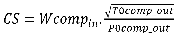 Wcomp_in is the mass flow rate (kg/s) at entry to the engine core;T0comp_out is the stagnation temperature at exit to the compressor;P0comp out is the stagnation pressure at exit to the compressor; anda thrust to core efficiency ratio TC is in the range of from 1.5 × 10⁷ kNkg-1sPa to 4.0 × 10⁷ kNkq-1sPa, where the thrust to core efficiency ratio is defined as TC =
 characterised in that: the second turbine (17) comprises at least two rows of stator vanes (171, 173) and two rows of rotor blades (174); the axially most upstream row of stator vanes (171) and the most axially upstream row of rotor blades (174) are manufactured using a nickel alloy and comprise one or more internal cooling passages and/or film cooling holes;the second most axially upstream row of stator vanes (173) and the second most axially upstream row of rotor blades (174) comprise a ceramic matrix composite.
 - A gas turbine engine according to claim 1, wherein the thrust to core efficiency ratio TC is in the range of from 1.5 × 10⁷ kNkg-1sPa to 3.5 × 10⁷ kNkg-1sPa, optionally 1.5 × 10⁷ kNkg-1sPa to 3 × 10⁷ kNkg-1sPa, optionally in the range of 2 × 10⁷ kNkg-1sPa to 3 × 10⁷ kNkg-1sPa.
- A gas turbine engine according to claim 1 or claim 2, wherein a fan to core efficiency ratio FC is at least 2 × 10⁵ mkg-1sPa, optionally in the range of from 2 × 10⁵ mkg-1sPa to 3 × 10⁵ mkg-1sPa, optionally in the range of from 2 × 10⁵ mkg-1sPa to 2.5 × 10⁵ mkg-1sPa, where the fan to core efficiency ratio is defined as

- A gas turbine engine according to claim 4, wherein the mass of ceramic matrix composite in the second turbine is in the range of from 2% to 15% of the total mass of the second turbine, and optionally in the range of from 4% to 10% of the total mass of the second turbine
- A gas turbine engine (10) for an aircraft according to claim 4, wherein:the first turbine comprises at least one ceramic matrix composite component;and, optionally,the mass of ceramic matrix composite in the first and second turbines is in the range of from 1% to 15%, optionally 2% to 12%, of the total mass of the first and second turbines
- A gas turbine engine (10) according to any one of the preceding claims, wherein:the most axially upstream row of rotor blades is radially surrounded by seal segments (175); andthe seal segments comprise a ceramic matrix composite.
- A gas turbine engine (10) for an aircraft according to claim 6, wherein:
the second most axially upstream row of rotor blades is radially surrounded by ceramic matrix composite seal segments. - A gas turbine engine according to any one of the preceding claims, wherein the axially most upstream row of stator vanes (191) in the first turbine comprise a ceramic matrix composite.
- A gas turbine engine according to any one of the preceding claims, wherein the axially most upstream row of rotor blades (192) in the first turbine comprise a ceramic matrix composite, the gas turbine engine optionally further comprising ceramic matrix composite seal segments surrounding the axially most upstream row of rotor blades (192) in the first turbine.
- A gas turbine engine according to any one of the preceding claims, wherein:the turbine entry temperature, defined as the temperature at the inlet to the most axially upstream turbine rotor at a maximum power condition of the gas turbine engine, is in the range of from 1800K to 2100K, optionally at least 1850K, 1900K, 1950K or 2000K; and/orthe fan diameter is in the range of from 225cm to 400cm, optionally in the range of from 250cm to 280cm or 325 to 370cm; and/orthe gear reduction ratio of the gearbox is in the range of from 3.3 to 4; and/orthe maximum net thrust at sea level is in the range of from 160 kN to 550 kN, optionally in the range of from 160 kN to 250 kN or 300 kN to 500 kN.
Applications Claiming Priority (1)
| Application Number | Priority Date | Filing Date | Title |
|---|---|---|---|
| GBGB1813083.1A GB201813083D0 (en) | 2018-08-10 | 2018-08-10 | Efficient gas turbine engine |
Publications (2)
| Publication Number | Publication Date |
|---|---|
| EP3608510A1 EP3608510A1 (en) | 2020-02-12 |
| EP3608510B1 true EP3608510B1 (en) | 2024-07-03 |
Family
ID=63667211
Family Applications (1)
| Application Number | Title | Priority Date | Filing Date |
|---|---|---|---|
| EP19189308.0A Active EP3608510B1 (en) | 2018-08-10 | 2019-07-31 | Gas turbine engine with ceramic matrix composite turbine components |
Country Status (4)
| Country | Link |
|---|---|
| US (1) | US20200049021A1 (en) |
| EP (1) | EP3608510B1 (en) |
| CN (1) | CN110821673A (en) |
| GB (1) | GB201813083D0 (en) |
Families Citing this family (5)
| Publication number | Priority date | Publication date | Assignee | Title |
|---|---|---|---|---|
| GB201903261D0 (en) | 2019-03-11 | 2019-04-24 | Rolls Royce Plc | Efficient gas turbine engine installation and operation |
| GB201903257D0 (en) * | 2019-03-11 | 2019-04-24 | Rolls Royce Plc | Efficient gas turbine engine installation and operation |
| EP4148250B1 (en) | 2021-09-08 | 2025-08-06 | Rolls-Royce plc | An improved gas turbine engine |
| EP4148263A1 (en) * | 2021-09-08 | 2023-03-15 | Rolls-Royce plc | An improved gas turbine engine |
| US12467366B2 (en) * | 2023-12-01 | 2025-11-11 | General Electric Company | Turbine engine with a nozzle having cooling features |
Family Cites Families (13)
| Publication number | Priority date | Publication date | Assignee | Title |
|---|---|---|---|---|
| US9915154B2 (en) * | 2011-05-26 | 2018-03-13 | United Technologies Corporation | Ceramic matrix composite airfoil structures for a gas turbine engine |
| US20130192266A1 (en) * | 2012-01-31 | 2013-08-01 | United Technologies Corporation | Geared turbofan gas turbine engine architecture |
| US20130192196A1 (en) * | 2012-01-31 | 2013-08-01 | Gabriel L. Suciu | Gas turbine engine with high speed low pressure turbine section |
| US10309232B2 (en) * | 2012-02-29 | 2019-06-04 | United Technologies Corporation | Gas turbine engine with stage dependent material selection for blades and disk |
| US20130236302A1 (en) * | 2012-03-12 | 2013-09-12 | Charles Alexander Smith | In-situ gas turbine rotor blade and casing clearance control |
| US9624827B2 (en) * | 2013-03-15 | 2017-04-18 | United Technologies Corporation | Thrust efficient turbofan engine |
| EP3027853B1 (en) * | 2013-07-29 | 2021-05-19 | Raytheon Technologies Corporation | Gas turbine engine cmc airfoil assembly |
| WO2015031764A1 (en) * | 2013-08-29 | 2015-03-05 | United Technologies Corporation | Blade outer air seal made of ceramic matrix composite |
| CN204021254U (en) * | 2014-07-03 | 2014-12-17 | 刘泰麟 | A kind of solar power flight instruments |
| FR3031136B1 (en) * | 2014-12-26 | 2019-11-01 | Safran Aircraft Engines | TURBOMACHINE ROTOR WITH OPTIMIZED SUPPORT SURFACES |
| JP6614407B2 (en) * | 2015-06-10 | 2019-12-04 | 株式会社Ihi | Turbine |
| US20180216575A1 (en) * | 2017-01-27 | 2018-08-02 | General Electric Company | Cool core gas turbine engine |
| CN107755668B (en) * | 2017-09-20 | 2020-03-17 | 上海交通大学 | Method for preparing reinforced nickel-based high-temperature alloy composite material single crystal blade |
-
2018
- 2018-08-10 GB GBGB1813083.1A patent/GB201813083D0/en not_active Ceased
-
2019
- 2019-05-28 US US16/423,343 patent/US20200049021A1/en not_active Abandoned
- 2019-07-31 CN CN201910700160.XA patent/CN110821673A/en active Pending
- 2019-07-31 EP EP19189308.0A patent/EP3608510B1/en active Active
Also Published As
| Publication number | Publication date |
|---|---|
| CN110821673A (en) | 2020-02-21 |
| EP3608510A1 (en) | 2020-02-12 |
| US20200049021A1 (en) | 2020-02-13 |
| GB201813083D0 (en) | 2018-09-26 |
Similar Documents
| Publication | Publication Date | Title |
|---|---|---|
| EP3608510B1 (en) | Gas turbine engine with ceramic matrix composite turbine components | |
| EP3608508B1 (en) | Gas turbine engine with ceramic matrix composite turbine components | |
| EP3608509B1 (en) | Gas turbine engine with ceramic matrix composite turbine components | |
| US12247497B2 (en) | Airfoil attachment for turbine rotor | |
| EP3808963B1 (en) | Gas turbine engine | |
| US11629668B2 (en) | High pressure ratio gas turbine engine | |
| US12146440B2 (en) | Efficient aircraft engine | |
| US12454917B2 (en) | Gas turbine engine | |
| EP3608511B1 (en) | Gas turbine engine with ceramic matrix composite turbine components | |
| US20220307448A1 (en) | Efficient gas turbine engine | |
| US11466617B2 (en) | Gas turbine engine with efficient thrust generation | |
| US20200049067A1 (en) | Aircraft engine with high propulsive and thermal efficiency |
Legal Events
| Date | Code | Title | Description |
|---|---|---|---|
| PUAI | Public reference made under article 153(3) epc to a published international application that has entered the european phase |
Free format text: ORIGINAL CODE: 0009012 |
|
| STAA | Information on the status of an ep patent application or granted ep patent |
Free format text: STATUS: THE APPLICATION HAS BEEN PUBLISHED |
|
| AK | Designated contracting states |
Kind code of ref document: A1 Designated state(s): AL AT BE BG CH CY CZ DE DK EE ES FI FR GB GR HR HU IE IS IT LI LT LU LV MC MK MT NL NO PL PT RO RS SE SI SK SM TR |
|
| RAP1 | Party data changed (applicant data changed or rights of an application transferred) |
Owner name: ROLLS-ROYCE PLC |
|
| STAA | Information on the status of an ep patent application or granted ep patent |
Free format text: STATUS: REQUEST FOR EXAMINATION WAS MADE |
|
| 17P | Request for examination filed |
Effective date: 20200804 |
|
| RBV | Designated contracting states (corrected) |
Designated state(s): AL AT BE BG CH CY CZ DE DK EE ES FI FR GB GR HR HU IE IS IT LI LT LU LV MC MK MT NL NO PL PT RO RS SE SI SK SM TR |
|
| STAA | Information on the status of an ep patent application or granted ep patent |
Free format text: STATUS: EXAMINATION IS IN PROGRESS |
|
| 17Q | First examination report despatched |
Effective date: 20220630 |
|
| GRAP | Despatch of communication of intention to grant a patent |
Free format text: ORIGINAL CODE: EPIDOSNIGR1 |
|
| STAA | Information on the status of an ep patent application or granted ep patent |
Free format text: STATUS: GRANT OF PATENT IS INTENDED |
|
| INTG | Intention to grant announced |
Effective date: 20240325 |
|
| GRAS | Grant fee paid |
Free format text: ORIGINAL CODE: EPIDOSNIGR3 |
|
| GRAA | (expected) grant |
Free format text: ORIGINAL CODE: 0009210 |
|
| STAA | Information on the status of an ep patent application or granted ep patent |
Free format text: STATUS: THE PATENT HAS BEEN GRANTED |
|
| P01 | Opt-out of the competence of the unified patent court (upc) registered |
Effective date: 20240515 |
|
| AK | Designated contracting states |
Kind code of ref document: B1 Designated state(s): AL AT BE BG CH CY CZ DE DK EE ES FI FR GB GR HR HU IE IS IT LI LT LU LV MC MK MT NL NO PL PT RO RS SE SI SK SM TR |
|
| REG | Reference to a national code |
Ref country code: CH Ref legal event code: EP |
|
| REG | Reference to a national code |
Ref country code: DE Ref legal event code: R096 Ref document number: 602019054471 Country of ref document: DE |
|
| REG | Reference to a national code |
Ref country code: LT Ref legal event code: MG9D |
|
| REG | Reference to a national code |
Ref country code: NL Ref legal event code: MP Effective date: 20240703 |
|
| PG25 | Lapsed in a contracting state [announced via postgrant information from national office to epo] |
Ref country code: PT Free format text: LAPSE BECAUSE OF FAILURE TO SUBMIT A TRANSLATION OF THE DESCRIPTION OR TO PAY THE FEE WITHIN THE PRESCRIBED TIME-LIMIT Effective date: 20241104 |
|
| REG | Reference to a national code |
Ref country code: AT Ref legal event code: MK05 Ref document number: 1700010 Country of ref document: AT Kind code of ref document: T Effective date: 20240703 |
|
| PG25 | Lapsed in a contracting state [announced via postgrant information from national office to epo] |
Ref country code: NL Free format text: LAPSE BECAUSE OF FAILURE TO SUBMIT A TRANSLATION OF THE DESCRIPTION OR TO PAY THE FEE WITHIN THE PRESCRIBED TIME-LIMIT Effective date: 20240703 |
|
| PG25 | Lapsed in a contracting state [announced via postgrant information from national office to epo] |
Ref country code: PT Free format text: LAPSE BECAUSE OF FAILURE TO SUBMIT A TRANSLATION OF THE DESCRIPTION OR TO PAY THE FEE WITHIN THE PRESCRIBED TIME-LIMIT Effective date: 20241104 Ref country code: NL Free format text: LAPSE BECAUSE OF FAILURE TO SUBMIT A TRANSLATION OF THE DESCRIPTION OR TO PAY THE FEE WITHIN THE PRESCRIBED TIME-LIMIT Effective date: 20240703 |
|
| PG25 | Lapsed in a contracting state [announced via postgrant information from national office to epo] |
Ref country code: NO Free format text: LAPSE BECAUSE OF FAILURE TO SUBMIT A TRANSLATION OF THE DESCRIPTION OR TO PAY THE FEE WITHIN THE PRESCRIBED TIME-LIMIT Effective date: 20241003 |
|
| PG25 | Lapsed in a contracting state [announced via postgrant information from national office to epo] |
Ref country code: GR Free format text: LAPSE BECAUSE OF FAILURE TO SUBMIT A TRANSLATION OF THE DESCRIPTION OR TO PAY THE FEE WITHIN THE PRESCRIBED TIME-LIMIT Effective date: 20241004 Ref country code: FI Free format text: LAPSE BECAUSE OF FAILURE TO SUBMIT A TRANSLATION OF THE DESCRIPTION OR TO PAY THE FEE WITHIN THE PRESCRIBED TIME-LIMIT Effective date: 20240703 Ref country code: PL Free format text: LAPSE BECAUSE OF FAILURE TO SUBMIT A TRANSLATION OF THE DESCRIPTION OR TO PAY THE FEE WITHIN THE PRESCRIBED TIME-LIMIT Effective date: 20240703 |
|
| PG25 | Lapsed in a contracting state [announced via postgrant information from national office to epo] |
Ref country code: BG Free format text: LAPSE BECAUSE OF FAILURE TO SUBMIT A TRANSLATION OF THE DESCRIPTION OR TO PAY THE FEE WITHIN THE PRESCRIBED TIME-LIMIT Effective date: 20240703 |
|
| PG25 | Lapsed in a contracting state [announced via postgrant information from national office to epo] |
Ref country code: LV Free format text: LAPSE BECAUSE OF FAILURE TO SUBMIT A TRANSLATION OF THE DESCRIPTION OR TO PAY THE FEE WITHIN THE PRESCRIBED TIME-LIMIT Effective date: 20240703 |
|
| PG25 | Lapsed in a contracting state [announced via postgrant information from national office to epo] |
Ref country code: AT Free format text: LAPSE BECAUSE OF FAILURE TO SUBMIT A TRANSLATION OF THE DESCRIPTION OR TO PAY THE FEE WITHIN THE PRESCRIBED TIME-LIMIT Effective date: 20240703 Ref country code: IS Free format text: LAPSE BECAUSE OF FAILURE TO SUBMIT A TRANSLATION OF THE DESCRIPTION OR TO PAY THE FEE WITHIN THE PRESCRIBED TIME-LIMIT Effective date: 20241103 |
|
| PG25 | Lapsed in a contracting state [announced via postgrant information from national office to epo] |
Ref country code: HR Free format text: LAPSE BECAUSE OF FAILURE TO SUBMIT A TRANSLATION OF THE DESCRIPTION OR TO PAY THE FEE WITHIN THE PRESCRIBED TIME-LIMIT Effective date: 20240703 Ref country code: CZ Free format text: LAPSE BECAUSE OF FAILURE TO SUBMIT A TRANSLATION OF THE DESCRIPTION OR TO PAY THE FEE WITHIN THE PRESCRIBED TIME-LIMIT Effective date: 20240703 |
|
| PG25 | Lapsed in a contracting state [announced via postgrant information from national office to epo] |
Ref country code: ES Free format text: LAPSE BECAUSE OF FAILURE TO SUBMIT A TRANSLATION OF THE DESCRIPTION OR TO PAY THE FEE WITHIN THE PRESCRIBED TIME-LIMIT Effective date: 20240703 Ref country code: RS Free format text: LAPSE BECAUSE OF FAILURE TO SUBMIT A TRANSLATION OF THE DESCRIPTION OR TO PAY THE FEE WITHIN THE PRESCRIBED TIME-LIMIT Effective date: 20241003 |
|
| PG25 | Lapsed in a contracting state [announced via postgrant information from national office to epo] |
Ref country code: RS Free format text: LAPSE BECAUSE OF FAILURE TO SUBMIT A TRANSLATION OF THE DESCRIPTION OR TO PAY THE FEE WITHIN THE PRESCRIBED TIME-LIMIT Effective date: 20241003 Ref country code: PL Free format text: LAPSE BECAUSE OF FAILURE TO SUBMIT A TRANSLATION OF THE DESCRIPTION OR TO PAY THE FEE WITHIN THE PRESCRIBED TIME-LIMIT Effective date: 20240703 Ref country code: NO Free format text: LAPSE BECAUSE OF FAILURE TO SUBMIT A TRANSLATION OF THE DESCRIPTION OR TO PAY THE FEE WITHIN THE PRESCRIBED TIME-LIMIT Effective date: 20241003 Ref country code: LV Free format text: LAPSE BECAUSE OF FAILURE TO SUBMIT A TRANSLATION OF THE DESCRIPTION OR TO PAY THE FEE WITHIN THE PRESCRIBED TIME-LIMIT Effective date: 20240703 Ref country code: IS Free format text: LAPSE BECAUSE OF FAILURE TO SUBMIT A TRANSLATION OF THE DESCRIPTION OR TO PAY THE FEE WITHIN THE PRESCRIBED TIME-LIMIT Effective date: 20241103 Ref country code: HR Free format text: LAPSE BECAUSE OF FAILURE TO SUBMIT A TRANSLATION OF THE DESCRIPTION OR TO PAY THE FEE WITHIN THE PRESCRIBED TIME-LIMIT Effective date: 20240703 Ref country code: GR Free format text: LAPSE BECAUSE OF FAILURE TO SUBMIT A TRANSLATION OF THE DESCRIPTION OR TO PAY THE FEE WITHIN THE PRESCRIBED TIME-LIMIT Effective date: 20241004 Ref country code: FI Free format text: LAPSE BECAUSE OF FAILURE TO SUBMIT A TRANSLATION OF THE DESCRIPTION OR TO PAY THE FEE WITHIN THE PRESCRIBED TIME-LIMIT Effective date: 20240703 Ref country code: ES Free format text: LAPSE BECAUSE OF FAILURE TO SUBMIT A TRANSLATION OF THE DESCRIPTION OR TO PAY THE FEE WITHIN THE PRESCRIBED TIME-LIMIT Effective date: 20240703 Ref country code: CZ Free format text: LAPSE BECAUSE OF FAILURE TO SUBMIT A TRANSLATION OF THE DESCRIPTION OR TO PAY THE FEE WITHIN THE PRESCRIBED TIME-LIMIT Effective date: 20240703 Ref country code: BG Free format text: LAPSE BECAUSE OF FAILURE TO SUBMIT A TRANSLATION OF THE DESCRIPTION OR TO PAY THE FEE WITHIN THE PRESCRIBED TIME-LIMIT Effective date: 20240703 Ref country code: AT Free format text: LAPSE BECAUSE OF FAILURE TO SUBMIT A TRANSLATION OF THE DESCRIPTION OR TO PAY THE FEE WITHIN THE PRESCRIBED TIME-LIMIT Effective date: 20240703 |
|
| REG | Reference to a national code |
Ref country code: DE Ref legal event code: R119 Ref document number: 602019054471 Country of ref document: DE |
|
| REG | Reference to a national code |
Ref country code: CH Ref legal event code: PL |
|
| PG25 | Lapsed in a contracting state [announced via postgrant information from national office to epo] |
Ref country code: LU Free format text: LAPSE BECAUSE OF NON-PAYMENT OF DUE FEES Effective date: 20240731 |
|
| PG25 | Lapsed in a contracting state [announced via postgrant information from national office to epo] |
Ref country code: LU Free format text: LAPSE BECAUSE OF NON-PAYMENT OF DUE FEES Effective date: 20240731 |
|
| PG25 | Lapsed in a contracting state [announced via postgrant information from national office to epo] |
Ref country code: DE Free format text: LAPSE BECAUSE OF NON-PAYMENT OF DUE FEES Effective date: 20250201 |
|
| PG25 | Lapsed in a contracting state [announced via postgrant information from national office to epo] |
Ref country code: DK Free format text: LAPSE BECAUSE OF FAILURE TO SUBMIT A TRANSLATION OF THE DESCRIPTION OR TO PAY THE FEE WITHIN THE PRESCRIBED TIME-LIMIT Effective date: 20240703 Ref country code: SM Free format text: LAPSE BECAUSE OF FAILURE TO SUBMIT A TRANSLATION OF THE DESCRIPTION OR TO PAY THE FEE WITHIN THE PRESCRIBED TIME-LIMIT Effective date: 20240703 Ref country code: RO Free format text: LAPSE BECAUSE OF FAILURE TO SUBMIT A TRANSLATION OF THE DESCRIPTION OR TO PAY THE FEE WITHIN THE PRESCRIBED TIME-LIMIT Effective date: 20240703 |
|
| PG25 | Lapsed in a contracting state [announced via postgrant information from national office to epo] |
Ref country code: BE Free format text: LAPSE BECAUSE OF NON-PAYMENT OF DUE FEES Effective date: 20240731 Ref country code: MC Free format text: LAPSE BECAUSE OF FAILURE TO SUBMIT A TRANSLATION OF THE DESCRIPTION OR TO PAY THE FEE WITHIN THE PRESCRIBED TIME-LIMIT Effective date: 20240703 Ref country code: CH Free format text: LAPSE BECAUSE OF NON-PAYMENT OF DUE FEES Effective date: 20240731 Ref country code: EE Free format text: LAPSE BECAUSE OF FAILURE TO SUBMIT A TRANSLATION OF THE DESCRIPTION OR TO PAY THE FEE WITHIN THE PRESCRIBED TIME-LIMIT Effective date: 20240703 |
|
| PG25 | Lapsed in a contracting state [announced via postgrant information from national office to epo] |
Ref country code: SK Free format text: LAPSE BECAUSE OF FAILURE TO SUBMIT A TRANSLATION OF THE DESCRIPTION OR TO PAY THE FEE WITHIN THE PRESCRIBED TIME-LIMIT Effective date: 20240703 Ref country code: IT Free format text: LAPSE BECAUSE OF FAILURE TO SUBMIT A TRANSLATION OF THE DESCRIPTION OR TO PAY THE FEE WITHIN THE PRESCRIBED TIME-LIMIT Effective date: 20240703 |
|
| PLBE | No opposition filed within time limit |
Free format text: ORIGINAL CODE: 0009261 |
|
| STAA | Information on the status of an ep patent application or granted ep patent |
Free format text: STATUS: NO OPPOSITION FILED WITHIN TIME LIMIT |
|
| REG | Reference to a national code |
Ref country code: BE Ref legal event code: MM Effective date: 20240731 |
|
| 26N | No opposition filed |
Effective date: 20250404 |
|
| PG25 | Lapsed in a contracting state [announced via postgrant information from national office to epo] |
Ref country code: IE Free format text: LAPSE BECAUSE OF NON-PAYMENT OF DUE FEES Effective date: 20240731 |
|
| PG25 | Lapsed in a contracting state [announced via postgrant information from national office to epo] |
Ref country code: SE Free format text: LAPSE BECAUSE OF FAILURE TO SUBMIT A TRANSLATION OF THE DESCRIPTION OR TO PAY THE FEE WITHIN THE PRESCRIBED TIME-LIMIT Effective date: 20240703 |
|
| PGFP | Annual fee paid to national office [announced via postgrant information from national office to epo] |
Ref country code: GB Payment date: 20250722 Year of fee payment: 7 |
|
| PGFP | Annual fee paid to national office [announced via postgrant information from national office to epo] |
Ref country code: FR Payment date: 20250725 Year of fee payment: 7 |
|
| PG25 | Lapsed in a contracting state [announced via postgrant information from national office to epo] |
Ref country code: CY Free format text: LAPSE BECAUSE OF FAILURE TO SUBMIT A TRANSLATION OF THE DESCRIPTION OR TO PAY THE FEE WITHIN THE PRESCRIBED TIME-LIMIT; INVALID AB INITIO Effective date: 20190731 |
|
| PG25 | Lapsed in a contracting state [announced via postgrant information from national office to epo] |
Ref country code: HU Free format text: LAPSE BECAUSE OF FAILURE TO SUBMIT A TRANSLATION OF THE DESCRIPTION OR TO PAY THE FEE WITHIN THE PRESCRIBED TIME-LIMIT; INVALID AB INITIO Effective date: 20190731 |