EP3608177B1 - Power supply system - Google Patents
Power supply system Download PDFInfo
- Publication number
- EP3608177B1 EP3608177B1 EP17904519.0A EP17904519A EP3608177B1 EP 3608177 B1 EP3608177 B1 EP 3608177B1 EP 17904519 A EP17904519 A EP 17904519A EP 3608177 B1 EP3608177 B1 EP 3608177B1
- Authority
- EP
- European Patent Office
- Prior art keywords
- power
- voltage converter
- power supply
- vehicle
- electric
- Prior art date
- Legal status (The legal status is an assumption and is not a legal conclusion. Google has not performed a legal analysis and makes no representation as to the accuracy of the status listed.)
- Active
Links
Images

Classifications
-
- H—ELECTRICITY
- H02—GENERATION; CONVERSION OR DISTRIBUTION OF ELECTRIC POWER
- H02J—ELECTRIC POWER NETWORKS; CIRCUIT ARRANGEMENTS OR SYSTEMS FOR SUPPLYING OR DISTRIBUTING ELECTRIC POWER; SYSTEMS FOR STORING ELECTRIC ENERGY
- H02J1/00—Circuit arrangements for DC mains or DC distribution networks
- H02J1/001—Hot plugging or unplugging of load or power modules to or from power distribution networks
-
- B—PERFORMING OPERATIONS; TRANSPORTING
- B60—VEHICLES IN GENERAL
- B60L—PROPULSION OF ELECTRICALLY-PROPELLED VEHICLES; SUPPLYING ELECTRIC POWER FOR AUXILIARY EQUIPMENT OF ELECTRICALLY-PROPELLED VEHICLES; ELECTRODYNAMIC BRAKE SYSTEMS FOR VEHICLES IN GENERAL; MAGNETIC SUSPENSION OR LEVITATION FOR VEHICLES; MONITORING OPERATING VARIABLES OF ELECTRICALLY-PROPELLED VEHICLES; ELECTRIC SAFETY DEVICES FOR ELECTRICALLY-PROPELLED VEHICLES
- B60L1/00—Supplying electric power to auxiliary equipment of vehicles
- B60L1/003—Supplying electric power to auxiliary equipment of vehicles to auxiliary motors, e.g. for pumps, compressors
-
- B—PERFORMING OPERATIONS; TRANSPORTING
- B60—VEHICLES IN GENERAL
- B60L—PROPULSION OF ELECTRICALLY-PROPELLED VEHICLES; SUPPLYING ELECTRIC POWER FOR AUXILIARY EQUIPMENT OF ELECTRICALLY-PROPELLED VEHICLES; ELECTRODYNAMIC BRAKE SYSTEMS FOR VEHICLES IN GENERAL; MAGNETIC SUSPENSION OR LEVITATION FOR VEHICLES; MONITORING OPERATING VARIABLES OF ELECTRICALLY-PROPELLED VEHICLES; ELECTRIC SAFETY DEVICES FOR ELECTRICALLY-PROPELLED VEHICLES
- B60L1/00—Supplying electric power to auxiliary equipment of vehicles
- B60L1/02—Supplying electric power to auxiliary equipment of vehicles to electric heating circuits
-
- B—PERFORMING OPERATIONS; TRANSPORTING
- B60—VEHICLES IN GENERAL
- B60L—PROPULSION OF ELECTRICALLY-PROPELLED VEHICLES; SUPPLYING ELECTRIC POWER FOR AUXILIARY EQUIPMENT OF ELECTRICALLY-PROPELLED VEHICLES; ELECTRODYNAMIC BRAKE SYSTEMS FOR VEHICLES IN GENERAL; MAGNETIC SUSPENSION OR LEVITATION FOR VEHICLES; MONITORING OPERATING VARIABLES OF ELECTRICALLY-PROPELLED VEHICLES; ELECTRIC SAFETY DEVICES FOR ELECTRICALLY-PROPELLED VEHICLES
- B60L1/00—Supplying electric power to auxiliary equipment of vehicles
- B60L1/02—Supplying electric power to auxiliary equipment of vehicles to electric heating circuits
- B60L1/04—Supplying electric power to auxiliary equipment of vehicles to electric heating circuits fed by the power supply line
-
- B—PERFORMING OPERATIONS; TRANSPORTING
- B60—VEHICLES IN GENERAL
- B60L—PROPULSION OF ELECTRICALLY-PROPELLED VEHICLES; SUPPLYING ELECTRIC POWER FOR AUXILIARY EQUIPMENT OF ELECTRICALLY-PROPELLED VEHICLES; ELECTRODYNAMIC BRAKE SYSTEMS FOR VEHICLES IN GENERAL; MAGNETIC SUSPENSION OR LEVITATION FOR VEHICLES; MONITORING OPERATING VARIABLES OF ELECTRICALLY-PROPELLED VEHICLES; ELECTRIC SAFETY DEVICES FOR ELECTRICALLY-PROPELLED VEHICLES
- B60L1/00—Supplying electric power to auxiliary equipment of vehicles
- B60L1/14—Supplying electric power to auxiliary equipment of vehicles to electric lighting circuits
-
- B—PERFORMING OPERATIONS; TRANSPORTING
- B60—VEHICLES IN GENERAL
- B60L—PROPULSION OF ELECTRICALLY-PROPELLED VEHICLES; SUPPLYING ELECTRIC POWER FOR AUXILIARY EQUIPMENT OF ELECTRICALLY-PROPELLED VEHICLES; ELECTRODYNAMIC BRAKE SYSTEMS FOR VEHICLES IN GENERAL; MAGNETIC SUSPENSION OR LEVITATION FOR VEHICLES; MONITORING OPERATING VARIABLES OF ELECTRICALLY-PROPELLED VEHICLES; ELECTRIC SAFETY DEVICES FOR ELECTRICALLY-PROPELLED VEHICLES
- B60L1/00—Supplying electric power to auxiliary equipment of vehicles
- B60L1/14—Supplying electric power to auxiliary equipment of vehicles to electric lighting circuits
- B60L1/16—Supplying electric power to auxiliary equipment of vehicles to electric lighting circuits fed by the power supply line
-
- B—PERFORMING OPERATIONS; TRANSPORTING
- B60—VEHICLES IN GENERAL
- B60Q—ARRANGEMENT OF SIGNALLING OR LIGHTING DEVICES, THE MOUNTING OR SUPPORTING THEREOF OR CIRCUITS THEREFOR, FOR VEHICLES IN GENERAL
- B60Q3/00—Arrangement of lighting devices for vehicle interiors; Lighting devices specially adapted for vehicle interiors
- B60Q3/70—Arrangement of lighting devices for vehicle interiors; Lighting devices specially adapted for vehicle interiors characterised by the purpose
- B60Q3/74—Arrangement of lighting devices for vehicle interiors; Lighting devices specially adapted for vehicle interiors characterised by the purpose for overall compartment lighting; for overall compartment lighting in combination with specific lighting, e.g. room lamps with reading lamps
-
- B—PERFORMING OPERATIONS; TRANSPORTING
- B60—VEHICLES IN GENERAL
- B60R—VEHICLES, VEHICLE FITTINGS, OR VEHICLE PARTS, NOT OTHERWISE PROVIDED FOR
- B60R16/00—Electric or fluid circuits specially adapted for vehicles and not otherwise provided for; Arrangement of elements of electric or fluid circuits specially adapted for vehicles and not otherwise provided for
- B60R16/02—Electric or fluid circuits specially adapted for vehicles and not otherwise provided for; Arrangement of elements of electric or fluid circuits specially adapted for vehicles and not otherwise provided for electric constitutive elements
-
- H—ELECTRICITY
- H02—GENERATION; CONVERSION OR DISTRIBUTION OF ELECTRIC POWER
- H02G—INSTALLATION OF ELECTRIC CABLES OR LINES, OR OF COMBINED OPTICAL AND ELECTRIC CABLES OR LINES
- H02G3/00—Installations of electric cables or lines or protective tubing therefor in or on buildings, equivalent structures or vehicles
- H02G3/02—Details
- H02G3/08—Distribution boxes; Connection or junction boxes
- H02G3/16—Distribution boxes; Connection or junction boxes structurally associated with support for line-connecting terminals within the box
-
- B—PERFORMING OPERATIONS; TRANSPORTING
- B60—VEHICLES IN GENERAL
- B60L—PROPULSION OF ELECTRICALLY-PROPELLED VEHICLES; SUPPLYING ELECTRIC POWER FOR AUXILIARY EQUIPMENT OF ELECTRICALLY-PROPELLED VEHICLES; ELECTRODYNAMIC BRAKE SYSTEMS FOR VEHICLES IN GENERAL; MAGNETIC SUSPENSION OR LEVITATION FOR VEHICLES; MONITORING OPERATING VARIABLES OF ELECTRICALLY-PROPELLED VEHICLES; ELECTRIC SAFETY DEVICES FOR ELECTRICALLY-PROPELLED VEHICLES
- B60L2210/00—Converter types
- B60L2210/10—DC to DC converters
Definitions
- the present invention relates to a power supply system.
- WO 02/062623 A1 relates to a vehicular lighting system, wherein an LED is powered by a battery via a power line and a voltage converter.
- the LED and the power converter may be located in an overhead console.
- Patent Literature 1 Japanese Patent Application Laid-open No. H09-189160
- an object of the present invention is to provide a power supply system capable of improving the workability of the wiring work of the feeder lines.
- the power supply system includes a housing disposed on the vehicle upper portion, wherein the housing is assembled with the voltage converter, the power distributor, and the load devices.
- the housing is disposed on the vehicle upper portion and on the front side in an advancing direction of the vehicle, and the coupling member is a front pillar disposed on the front side in the advancing direction.
- the power supply system according to the present invention has an effect in that the workability of the wiring work can be improved.
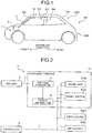
- FIG. 1 is a schematic diagram for explaining a power supply system according to the embodiment of the present invention.
- FIG. 2 is a schematic block diagram for explaining the power supply system in the embodiment of the present invention.
- FIG. 3 is a schematic block diagram for explaining the power supply system in the embodiment of the present invention.
- a power supply system 1 supplies, in a vehicle 100 such as an automobile, electric power to a plurality of load devices 8 arranged on a ceiling 102 in a vehicle interior 101.
- the ceiling 102 of the vehicle 100 is supported from below by a plurality of pillars (coupling members).
- the pillar is a hollow coupling member that couples a vehicle upper portion 100A with a vehicle lower portion 100B which will be described later.
- the ceiling 102 is supported by front pillars (coupling members) 103, center pillars (coupling members) 104, and rear pillars (coupling members) 105.
- the front pillars 103 are located on the front side in an advancing direction of the vehicle 100.
- the front pillars 103 are located at end portions in a vehicle width direction of a windshield.
- the center pillars 104 are located at the center in the advancing direction of the vehicle 100.
- the rear pillars 105 are located on the rear side in the advancing direction of the vehicle 100. That is, the rear pillars 105 are located at end portions in the vehicle width direction of a rear windshield.
- the vehicle upper portion 100A is a portion located above the pillars 103, 104, and 105 in the vertical direction including the ceiling 102 and the vicinity of the ceiling 102.
- the vehicle lower portion 100B is a portion located below the pillars 103, 104, and 105 in the vertical direction including a floor surface, a space below the floor surface (not depicted), an engine room, a trunk room, and the like.
- the power supply system 1 primarily includes a battery (power supply device) 2, a feeder line (power line) 3, a voltage converter 4, and a power distributor 5.
- the battery 2 is mounted on the vehicle lower portion 100B.
- the battery 2 is a secondary battery capable of storing electric power.
- the battery 2 supplies the electric power to the load devices 8 which will be described later.
- the feeder line 3 is wired from the battery 2 up to the ceiling 102 through the inside of the front pillar 103.
- the feeder line 3 electrically couples the battery 2 with the voltage converter 4 which will be described later.
- the feeder line 3 supplies the electric power output from the battery 2 to the voltage converter 4 at an as-is voltage.
- the feeder line 3 is made up of a single electric wire.
- the feeder line 3 branches into two electric wires 31 and 32 in a first power distributor 50 of an overhead console (housing) 10 which will be described later.
- the electric wire 31 is electrically coupled to a first voltage converter 41 which will be described later.
- the electric wire 31 branches into three electric wires 311, 312, and 313 in a second power distributor 51.
- the electric wires 311, 312, and 313 are electrically coupled to the respective load devices 8.
- the electric wire 32 is electrically coupled to a second voltage converter 42 which will be described later.
- the electric wire 32 branches into two electric wires 323 and 324 in a third power distributor 52.
- the electric wires 323 and 324 are electrically coupled to the respective load devices 8.
- the voltage converter 4 has a function of generating the electric power for which the voltage of the electric power supplied via the feeder line 3 is lowered to, for example, 12 V in accordance with a drive voltage of the load devices 8 described later.
- the voltage converter 4 is electrically coupled to the electric wires 31 and 32 and the power distributor 5 which will be described later.
- the voltage converter 4 is mounted above the front pillar 103.
- the first voltage converter 41 and second voltage converter 42 are disposed.
- the first voltage converter 41 generates an illumination power supply.
- the illumination power supply supplies the electric power when a headlight switch of headlights is ON
- the first voltage converter 41 is electrically coupled with the electric wire 31.
- the second voltage converter 42 generates a key-switch power supply.
- the key-switch power supply supplies the electric power when a key switch is ON or at a start position.
- the second voltage converter 42 is electrically coupled with the electric wire 32.
- the power distributor 5 distributes the electric power that is input from the feeder line 3 to the load devices 8 described later. In more detail, the power distributor 5 distributes and outputs the electric power depending on the number of the load devices 8.
- the power distributor 5 is mounted above the front pillar 103.
- the power distributor 5 is electrically coupled to the voltage converter 4 and the load devices 8 via the electric wires 31, 32, 311, 312, 313, 323, and 324.
- the first power distributor 50, the second power distributor 51, and the third power distributor 52 are disposed.
- the first power distributor 50 distributes the electric power depending on the number of the voltage converters 4.
- the first power distributor 50 divides the feeder line 3 into the two electric wires 31 and 32.
- the second power distributor 51 distributes the electric power depending on the number of the load devices 8 to which the illumination power supply is supplied.
- the second power distributor 51 divides the electric wire 31 into the three electric wires 311, 312, and 313.
- the electric power distributed by the second power distributor 51 is supplied to each of the load devices 8 via the electric wires 311, 312, and 313 that are wired on the back of the ceiling 102.
- the second power distributor 51 distributes the electric power supplied to a room lamp 81, a panel switch 82, and a rear heater 83.
- the third power distributor 52 distributes the electric power depending on the number of the load devices 8 to which the key-switch power supply is supplied.
- the third power distributor 52 divides the electric wire 32 into the two electric wires 323 and 324.
- the electric power distributed by the third power distributor 52 is supplied to each of the load devices 8 via the electric wires 323 and 324 that are wired on the back of the ceiling 102.
- the third power distributor 52 distributes the electric power supplied to the rear heater 83 and an air cleaner 84.
- the number of the electric wires to branch into is not limited thereto, and is defined depending on the number of the load devices 8 to be coupled as appropriate.
- a controller 6 has control of the load devices 8 described later.
- the controller 6 is mounted on the vehicle lower portion 100B.
- the controller 6 is electrically coupled to the load devices 8 via signal lines 7 which will be described later.
- the controller 6 outputs control signals to control the load devices 8.
- the signal lines 7 are wired from the controller 6 up to the ceiling 102 through the inside of the front pillar 103.
- the signal line 7 is a transmission line that transmits the control signal output from the controller 6 to the load device 8.
- the signal line 7 electrically couples the controller 6 with the load device 8.
- the signal lines 7 are wired in the same number as the number of the load devices 8 to which the control signal is transmitted.
- four signal lines 71, 72, 73, and 74 are wired.
- the load devices 8 are electrical components mounted on the ceiling 102.
- the room lamp 81, the panel switch 82, the rear heater 83, and the air cleaner 84 are disposed.
- the room lamp 81 is fitted to an overhead console 10 which will be described later.
- the room lamp 81 is a lighting fixture including an LED lighting fixture, for example.
- the room lamp 81 is turned on/off based on switch operation of the panel switch 82 described later.
- the room lamp 81 is driven based on the electric power supplied from the battery 2 via the electric wire 311, and the control signal input from the controller 6 via the signal line 71.
- the panel switch 82 is fitted to the overhead console 10 described later.
- the panel switch 82 is arranged with switches for performing various operations of the load devices 8.
- the panel switch 82 outputs a control signal via the signal line 7 not depicted to the load device 8 that is the subject of the switch operation.
- the panel switch 82 is driven based on the electric power supplied from the battery 2 via the electric wire 312, and the control signal input from the controller 6 via the signal line 72.
- the rear heater 83 is attached at the center of the vehicle interior 101 in the advancing direction and at the center of the ceiling 102 in the vehicle width direction.
- the rear heater 83 is a heater device for rear seats.
- the rear heater 83 is driven based on the electric power supplied from the battery 2 via the electric wires 313 and 323, and the control signal input from the controller 6 via the signal line 73.
- the air cleaner 84 is attached at the center of the vehicle interior 101 in the advancing direction and on the left side of the ceiling 102 in the vehicle width direction.
- the air cleaner 84 cleanses the air in the vehicle interior 101.
- the air cleaner 84 is driven based on the electric power supplied from the battery 2 via the electric wire 324, and the control signal input from the controller 6 via the signal line 74.
- the overhead console 10 is fitted to the ceiling 102.
- the overhead console 10 has a relay connector (not depicted) arranged on the outer circumference. This relay connector electrically couples the feeder line, the electric wires, and the signal lines wired inside the overhead console 10 with the externally wired feeder line, the electric wires, and the signal lines.
- the feeder line 3 is made up of, in the relay connector, a portion wired outside of the overhead console 10 and a portion wired inside of the overhead console 10 being electrically coupled, for example.
- an overhead console 10 a part of the feeder line 3, the electric wires 31, 32, 311, and 312, a part of the electric wires 313, 323, and 324, the voltage converter 4, the power distributor 5, the room lamp 81, and the panel switch 82 are attached.
- the overhead console 10 is attached on the front side of the ceiling 102 in the advancing direction and at the center in the vehicle width direction.
- the electric power output from the battery 2 is supplied to the overhead console 10 fitted to the ceiling 102 at an as-is voltage, via the feeder line 3 through the inside of the front pillar 103. Then, the electric power supplied to the overhead console 10 is distributed by the first power distributor 50 and is supplied to the voltage converter 4.
- the first power distributor 50 divides the feeder line 3 into the electric wires 31 and 32, and distributes the electric power that is supplied to the first voltage converter 41 and the second voltage converter 42. Then, the electric power supplied to the voltage converter 4 is lowered to, for example, 12 V by the voltage converter 4 in accordance with the voltage of the load device 8.
- a part of the electric power supplied to the voltage converter 4 is input to the first voltage converter 41 via the electric wire 31 and is converted into an illumination-power supply voltage. Furthermore, the remain of the electric power supplied to the voltage converter 4 is input to the second voltage converter 42 via the electric wire 32 and is converted into a key-switch power supply voltage. Then, the electric power for which the voltage has been lowered by the voltage converter 4 is supplied to the second power distributor 51 and the third power distributor 52. The electric power supplied to the second power distributor 51 and the third power distributor 52 is distributed by the second power distributor 51 and the third power distributor 52 and is output to the load devices 8.
- the second power distributor 51 divides the electric wire 31 into the electric wires 311, 312, and 313, and distributes the electric power that is supplied to the room lamp 81, the panel switch 82, and the rear heater 83. Furthermore, the third power distributor 52 divides the electric wire 32 into the electric wires 323 and 324, and distributes the electric power that is supplied to the rear heater 83 and the air cleaner 84.
- the control signals output from the controller 6 are output to the load devices 8 from the controller 6, via the signal lines 71, 72, 73, and 74 through the inside of the front pillar 103.
- the load devices 8 are driven based on the supplied electric power and the input control signals.
- the electric power output from the battery 2 can be supplied to the overhead console 10 via a single feeder line 3 wired to the ceiling 102 through the inside of the front pillar 103.
- the electric power can be distributed by the power distributor 5 in the overhead console 10 and be output to the load devices 8.
- the power supply system 1 only needs to wire a single feeder line 3 inside the front pillar 103, and the routing of the feeder line 3 in the front pillar 103 can be facilitated.
- the power supply system 1 can simplify the wiring of the feeder line 3, improve the workability of the wiring work, and reduce the time and effort needed for the wiring work.
- this power supply system 1 fitted to the overhead console 10 are a part of the feeder line 3, the electric wires 31, 32, 311, and 312, a part of the electric wires 313, 323, and 324, the voltage converter 4, the power distributor 5, the room lamp 81, and the panel switch 82. That is, a part of the feeder line 3, the electric wires 31, 32, 311, and 312, a part of the electric wires 313, 323, and 324, the voltage converter 4, the power distributor 5, the room lamp 81, and the panel switch 82, which are arranged on the front side of the ceiling 102 in the advancing direction and at the center in the vehicle width direction, are assembled to and integrated with the overhead console 10.
- the power supply system 1 can facilitate the routing of various devices and apparatuses mounted on the front side of the ceiling 102 in the advancing direction and at the center in the vehicle width direction and improve the workability of assembly work, the time and effort needed for the assembly work can be reduced.
- the electric wires 31, 32, 311, and 312 that electrically couple between the voltage converter 4 and the power distributor 5 and between the power distributor 5 and the room lamp 81 and the panel switch 82 can be wired in the overhead console 10.
- the power supply system 1 can simplify the wiring of the electric wires 31, 32, 311, and 312, improve the workability of the wiring work, and reduce the time and effort needed for the wiring work.
- the feeder line 3 is wired inside the front pillar 103. This makes it possible to shorten the length of the feeder line 3 that supplies the electric power to the overhead console 10 that is arranged on the front side of the ceiling 102 in the advancing direction and at the center in the vehicle width direction. Furthermore, because the feeder line 3 branches in the overhead console 10, the number of the electric wires wired to the ceiling 102 including the feeder line 3 can be reduced. Thus, the power supply system 1 can simplify the wiring of the feeder line 3, improve the workability of the wiring work, and reduce the time and effort needed for the wiring work.
- the feeder line 3 in the foregoing has been described to be wired through the inside of the front pillar 103, but the embodiment is not limited thereto and the feeder line 3 may be wired to the ceiling 102 through the center pillar 104 and the rear pillar 105. Furthermore, the overhead console 10 has been described to be attached on the front side of the ceiling 102 in the advancing direction and at the center in the vehicle width direction, but the embodiment is not limited to this location.
- the feeder line 3 in the foregoing has been described to be made up of a single electric wire, but the number of electric wires is not limited thereto, and it only needs to be smaller than the number of the load devices 8, that is, the number of the electric wires distributed in the power distributor 5. Specifically, when eight load devices 8 are arranged, two feeder lines 3 may be distributed to four electric wires each in the power distributor 5, for example. In this case also, as compared with a case where the power distributor 5 is disposed on the vehicle lower portion 100B and where eight feeder lines 3 are wired through the inside of the front pillar 103, it is possible to reduce the number of the feeder lines 3 wired through the inside of the front pillar 103.
- the voltage converter 4 in the foregoing has been described to be accommodated in the overhead console 10, but the embodiment is not limited thereto and the voltage converter 4 may be disposed on the vehicle lower portion 100B, for example.
- the voltage converter 4 is electrically coupled to the battery 2.
- the electric power for which the voltage is lowered by the voltage converter 4 is supplied to the power distributor 5 via a single feeder line 3 wired to the ceiling 102 through the inside of the front pillar 103.
- the electric power can be distributed by the power distributor 5 in the overhead console 10 and be output to the load devices 8.
- the load devices 8 in the foregoing have been exemplified as the room lamp 81, the panel switch 82, the rear heater 83, and the air cleaner 84, but the embodiment is not limited thereto, and they only need to be electrical components arranged on the ceiling 102 or on the vehicle upper portion 100A near the ceiling 102.
- the controller 6 in the foregoing has been described as to be mounted on the vehicle lower portion 100B, but the embodiment is not limited thereto and the controller 6 may be accommodated in the overhead console 10.
- the voltage converter 4 and the power distributor 5 in the foregoing have been described as independent devices and apparatuses, but they may be implemented on a single power supply device including an intelligent power switch (IPS), for example.
- IPS intelligent power switch
- the voltage converter 4 in the foregoing has been described as to convert the voltage into the illumination-power supply voltage by the first voltage converter 41 and to convert it into the key-switch power supply voltage by the second voltage converter 42, but the embodiment is not limited thereto and the voltage converter 4 may further convert it into an accessory-power supply voltage and a constant-power supply voltage, for example.
- the accessory-power supply supplies the electric power when the key switch is at an accessory position.
- the constant power supply supplies the electric power even when the key switch is Off.
Landscapes
- Engineering & Computer Science (AREA)
- Power Engineering (AREA)
- Mechanical Engineering (AREA)
- Transportation (AREA)
- Architecture (AREA)
- Civil Engineering (AREA)
- Structural Engineering (AREA)
- Charge And Discharge Circuits For Batteries Or The Like (AREA)
- Arrangement Or Mounting Of Propulsion Units For Vehicles (AREA)
Description
- The present invention relates to a power supply system.
- Conventionally, a technology that arranges, in a vehicle such as an automobile, electrical components (load devices), such as a room lamp and a receiver of a panel switch, on a ceiling of a vehicle interior has been known (for example, the following Patent Literature 1). In this technology, a receiving unit of the receiver of the panel switch and a controller thereof are built into the inside of the room lamp. A bulb and the receiver are powered from a feeder line that is coupled to a battery. This feeder line is wired to the room lamp from the battery through the inside of a pillar.
-
WO 02/062623 A1 - Patent Literature 1: Japanese Patent Application Laid-open No.
H09-189160 - Incidentally, when the number of electrical components arranged on the ceiling of the vehicle interior increases, the number of feeder lines wired inside the pillar increases. As a result, the wiring of the feeder lines inside the pillar becomes complicated, and the wiring work of the feeder lines needs time and effort. As just described, in the power supply to the electrical components arranged on the ceiling of the vehicle interior, there is room for improvement in that the wiring of the feeder lines is simplified and in that the workability of the wiring work of the feeder lines is improved.
- Thus, an object of the present invention is to provide a power supply system capable of improving the workability of the wiring work of the feeder lines. Solution to Problem
- This is achieved by the power supply system as defined in the independent claim. The dependent claims describe advantageous embodiments.
- Further, it is preferable that the power supply system includes a housing disposed on the vehicle upper portion, wherein the housing is assembled with the voltage converter, the power distributor, and the load devices.
- Further, it is preferable that the housing is disposed on the vehicle upper portion and on the front side in an advancing direction of the vehicle, and the coupling member is a front pillar disposed on the front side in the advancing direction.
- The power supply system according to the present invention has an effect in that the workability of the wiring work can be improved.
-
-
FIG. 1 is a schematic diagram for explaining a power supply system according to an embodiment of the present invention. -
FIG. 2 is a schematic block diagram for explaining the power supply system in the embodiment of the present invention. -
FIG. 3 is a schematic block diagram for explaining the power supply system in the embodiment of the present invention. - The following describes an exemplary embodiment of a power supply system according to the present invention in detail with reference to the accompanying drawings. The invention, however, is not intended to be limited by the embodiment. The constituent elements in the following embodiment include elements that are substitutable and easily achieved by a person skilled in the art, or elements that are substantially the same as the constituent elements.
-
FIG. 1 is a schematic diagram for explaining a power supply system according to the embodiment of the present invention.FIG. 2 is a schematic block diagram for explaining the power supply system in the embodiment of the present invention.FIG. 3 is a schematic block diagram for explaining the power supply system in the embodiment of the present invention. - A
power supply system 1 according to the present embodiment illustrated inFIG. 1 to FIG. 3 supplies, in avehicle 100 such as an automobile, electric power to a plurality ofload devices 8 arranged on aceiling 102 in avehicle interior 101. Theceiling 102 of thevehicle 100 is supported from below by a plurality of pillars (coupling members). The pillar is a hollow coupling member that couples a vehicleupper portion 100A with a vehiclelower portion 100B which will be described later. In the present embodiment, theceiling 102 is supported by front pillars (coupling members) 103, center pillars (coupling members) 104, and rear pillars (coupling members) 105. Thefront pillars 103 are located on the front side in an advancing direction of thevehicle 100. That is, thefront pillars 103 are located at end portions in a vehicle width direction of a windshield. Thecenter pillars 104 are located at the center in the advancing direction of thevehicle 100. Therear pillars 105 are located on the rear side in the advancing direction of thevehicle 100. That is, therear pillars 105 are located at end portions in the vehicle width direction of a rear windshield. The vehicleupper portion 100A is a portion located above thepillars ceiling 102 and the vicinity of theceiling 102. The vehiclelower portion 100B is a portion located below thepillars - The
power supply system 1 primarily includes a battery (power supply device) 2, a feeder line (power line) 3, avoltage converter 4, and apower distributor 5. - The
battery 2 is mounted on the vehiclelower portion 100B. Thebattery 2 is a secondary battery capable of storing electric power. Thebattery 2 supplies the electric power to theload devices 8 which will be described later. - The
feeder line 3 is wired from thebattery 2 up to theceiling 102 through the inside of thefront pillar 103. Thefeeder line 3 electrically couples thebattery 2 with thevoltage converter 4 which will be described later. Thefeeder line 3 supplies the electric power output from thebattery 2 to thevoltage converter 4 at an as-is voltage. In the present embodiment, thefeeder line 3 is made up of a single electric wire. Thefeeder line 3 branches into twoelectric wires first power distributor 50 of an overhead console (housing) 10 which will be described later. Theelectric wire 31 is electrically coupled to afirst voltage converter 41 which will be described later. Theelectric wire 31 branches into threeelectric wires second power distributor 51. Theelectric wires respective load devices 8. Theelectric wire 32 is electrically coupled to asecond voltage converter 42 which will be described later. Theelectric wire 32 branches into twoelectric wires third power distributor 52. Theelectric wires respective load devices 8. - The
voltage converter 4 has a function of generating the electric power for which the voltage of the electric power supplied via thefeeder line 3 is lowered to, for example, 12 V in accordance with a drive voltage of theload devices 8 described later. Thevoltage converter 4 is electrically coupled to theelectric wires power distributor 5 which will be described later. In the present embodiment, thevoltage converter 4 is mounted above thefront pillar 103. As thevoltage converter 4, thefirst voltage converter 41 andsecond voltage converter 42 are disposed. Thefirst voltage converter 41 generates an illumination power supply. The illumination power supply supplies the electric power when a headlight switch of headlights is ON Thefirst voltage converter 41 is electrically coupled with theelectric wire 31. Thesecond voltage converter 42 generates a key-switch power supply. The key-switch power supply supplies the electric power when a key switch is ON or at a start position. Thesecond voltage converter 42 is electrically coupled with theelectric wire 32. - The
power distributor 5 distributes the electric power that is input from thefeeder line 3 to theload devices 8 described later. In more detail, thepower distributor 5 distributes and outputs the electric power depending on the number of theload devices 8. Thepower distributor 5 is mounted above thefront pillar 103. Thepower distributor 5 is electrically coupled to thevoltage converter 4 and theload devices 8 via theelectric wires power distributor 5, thefirst power distributor 50, thesecond power distributor 51, and thethird power distributor 52 are disposed. Thefirst power distributor 50 distributes the electric power depending on the number of thevoltage converters 4. In the present embodiment, thefirst power distributor 50 divides thefeeder line 3 into the twoelectric wires second power distributor 51 distributes the electric power depending on the number of theload devices 8 to which the illumination power supply is supplied. In the present embodiment, thesecond power distributor 51 divides theelectric wire 31 into the threeelectric wires second power distributor 51 is supplied to each of theload devices 8 via theelectric wires ceiling 102. In the present embodiment, thesecond power distributor 51 distributes the electric power supplied to aroom lamp 81, apanel switch 82, and arear heater 83. Thethird power distributor 52 distributes the electric power depending on the number of theload devices 8 to which the key-switch power supply is supplied. In the present embodiment, thethird power distributor 52 divides theelectric wire 32 into the twoelectric wires third power distributor 52 is supplied to each of theload devices 8 via theelectric wires ceiling 102. In the present embodiment, thethird power distributor 52 distributes the electric power supplied to therear heater 83 and anair cleaner 84. The number of the electric wires to branch into is not limited thereto, and is defined depending on the number of theload devices 8 to be coupled as appropriate. - A
controller 6 has control of theload devices 8 described later. Thecontroller 6 is mounted on the vehiclelower portion 100B. Thecontroller 6 is electrically coupled to theload devices 8 viasignal lines 7 which will be described later. Thecontroller 6 outputs control signals to control theload devices 8. - The
signal lines 7 are wired from thecontroller 6 up to theceiling 102 through the inside of thefront pillar 103. Thesignal line 7 is a transmission line that transmits the control signal output from thecontroller 6 to theload device 8. Thesignal line 7 electrically couples thecontroller 6 with theload device 8. In the present embodiment, thesignal lines 7 are wired in the same number as the number of theload devices 8 to which the control signal is transmitted. In the present embodiment, foursignal lines - The
load devices 8 are electrical components mounted on theceiling 102. In the present embodiment, as theload devices 8, theroom lamp 81, thepanel switch 82, therear heater 83, and theair cleaner 84 are disposed. Theroom lamp 81 is fitted to anoverhead console 10 which will be described later. Theroom lamp 81 is a lighting fixture including an LED lighting fixture, for example.
Theroom lamp 81 is turned on/off based on switch operation of thepanel switch 82 described later. Theroom lamp 81 is driven based on the electric power supplied from thebattery 2 via theelectric wire 311, and the control signal input from thecontroller 6 via thesignal line 71. Thepanel switch 82 is fitted to theoverhead console 10 described later. Thepanel switch 82 is arranged with switches for performing various operations of theload devices 8. Thepanel switch 82 outputs a control signal via thesignal line 7 not depicted to theload device 8 that is the subject of the switch operation. Thepanel switch 82 is driven based on the electric power supplied from thebattery 2 via theelectric wire 312, and the control signal input from thecontroller 6 via thesignal line 72. Therear heater 83 is attached at the center of thevehicle interior 101 in the advancing direction and at the center of theceiling 102 in the vehicle width direction. Therear heater 83 is a heater device for rear seats. Therear heater 83 is driven based on the electric power supplied from thebattery 2 via theelectric wires controller 6 via thesignal line 73. Theair cleaner 84 is attached at the center of thevehicle interior 101 in the advancing direction and on the left side of theceiling 102 in the vehicle width direction. Theair cleaner 84 cleanses the air in thevehicle interior 101. Theair cleaner 84 is driven based on the electric power supplied from thebattery 2 via theelectric wire 324, and the control signal input from thecontroller 6 via thesignal line 74. - The
overhead console 10 is fitted to theceiling 102. Theoverhead console 10 has a relay connector (not depicted) arranged on the outer circumference. This relay connector electrically couples the feeder line, the electric wires, and the signal lines wired inside theoverhead console 10 with the externally wired feeder line, the electric wires, and the signal lines. In more detail, thefeeder line 3 is made up of, in the relay connector, a portion wired outside of theoverhead console 10 and a portion wired inside of theoverhead console 10 being electrically coupled, for example. In such anoverhead console 10, a part of thefeeder line 3, theelectric wires electric wires voltage converter 4, thepower distributor 5, theroom lamp 81, and thepanel switch 82 are attached. Theoverhead console 10 is attached on the front side of theceiling 102 in the advancing direction and at the center in the vehicle width direction. - Next, a power supply method and operation in the
power supply system 1 will be described. - The electric power output from the
battery 2 is supplied to theoverhead console 10 fitted to theceiling 102 at an as-is voltage, via thefeeder line 3 through the inside of thefront pillar 103. Then, the electric power supplied to theoverhead console 10 is distributed by thefirst power distributor 50 and is supplied to thevoltage converter 4. In more detail, thefirst power distributor 50 divides thefeeder line 3 into theelectric wires first voltage converter 41 and thesecond voltage converter 42. Then, the electric power supplied to thevoltage converter 4 is lowered to, for example, 12 V by thevoltage converter 4 in accordance with the voltage of theload device 8. In more detail, a part of the electric power supplied to thevoltage converter 4 is input to thefirst voltage converter 41 via theelectric wire 31 and is converted into an illumination-power supply voltage. Furthermore, the remain of the electric power supplied to thevoltage converter 4 is input to thesecond voltage converter 42 via theelectric wire 32 and is converted into a key-switch power supply voltage. Then, the electric power for which the voltage has been lowered by thevoltage converter 4 is supplied to thesecond power distributor 51 and thethird power distributor 52. The electric power supplied to thesecond power distributor 51 and thethird power distributor 52 is distributed by thesecond power distributor 51 and thethird power distributor 52 and is output to theload devices 8. In more detail, thesecond power distributor 51 divides theelectric wire 31 into theelectric wires room lamp 81, thepanel switch 82, and therear heater 83. Furthermore, thethird power distributor 52 divides theelectric wire 32 into theelectric wires rear heater 83 and theair cleaner 84. - The control signals output from the
controller 6 are output to theload devices 8 from thecontroller 6, via the signal lines 71, 72, 73, and 74 through the inside of thefront pillar 103. - Thus, the
load devices 8 are driven based on the supplied electric power and the input control signals. - According to the
power supply system 1 in the foregoing, the electric power output from thebattery 2 can be supplied to theoverhead console 10 via asingle feeder line 3 wired to theceiling 102 through the inside of thefront pillar 103. In thepower supply system 1, the electric power can be distributed by thepower distributor 5 in theoverhead console 10 and be output to theload devices 8. As a result, thepower supply system 1 only needs to wire asingle feeder line 3 inside thefront pillar 103, and the routing of thefeeder line 3 in thefront pillar 103 can be facilitated. Thus, thepower supply system 1 can simplify the wiring of thefeeder line 3, improve the workability of the wiring work, and reduce the time and effort needed for the wiring work. - According to this
power supply system 1, fitted to theoverhead console 10 are a part of thefeeder line 3, theelectric wires electric wires voltage converter 4, thepower distributor 5, theroom lamp 81, and thepanel switch 82. That is, a part of thefeeder line 3, theelectric wires electric wires voltage converter 4, thepower distributor 5, theroom lamp 81, and thepanel switch 82, which are arranged on the front side of theceiling 102 in the advancing direction and at the center in the vehicle width direction, are assembled to and integrated with theoverhead console 10. Thus, because thepower supply system 1 can facilitate the routing of various devices and apparatuses mounted on the front side of theceiling 102 in the advancing direction and at the center in the vehicle width direction and improve the workability of assembly work, the time and effort needed for the assembly work can be reduced. Furthermore, theelectric wires voltage converter 4 and thepower distributor 5 and between thepower distributor 5 and theroom lamp 81 and thepanel switch 82 can be wired in theoverhead console 10. Thus, thepower supply system 1 can simplify the wiring of theelectric wires - According to this
power supply system 1, thefeeder line 3 is wired inside thefront pillar 103. This makes it possible to shorten the length of thefeeder line 3 that supplies the electric power to theoverhead console 10 that is arranged on the front side of theceiling 102 in the advancing direction and at the center in the vehicle width direction. Furthermore, because thefeeder line 3 branches in theoverhead console 10, the number of the electric wires wired to theceiling 102 including thefeeder line 3 can be reduced. Thus, thepower supply system 1 can simplify the wiring of thefeeder line 3, improve the workability of the wiring work, and reduce the time and effort needed for the wiring work. - The above-described
power supply system 1 according to the embodiment of the present invention is not limited to the above-described embodiment, and various modifications can be made within the scope stated in claims. - The
feeder line 3 in the foregoing has been described to be wired through the inside of thefront pillar 103, but the embodiment is not limited thereto and thefeeder line 3 may be wired to theceiling 102 through thecenter pillar 104 and therear pillar 105. Furthermore, theoverhead console 10 has been described to be attached on the front side of theceiling 102 in the advancing direction and at the center in the vehicle width direction, but the embodiment is not limited to this location. - The
feeder line 3 in the foregoing has been described to be made up of a single electric wire, but the number of electric wires is not limited thereto, and it only needs to be smaller than the number of theload devices 8, that is, the number of the electric wires distributed in thepower distributor 5. Specifically, when eightload devices 8 are arranged, twofeeder lines 3 may be distributed to four electric wires each in thepower distributor 5, for example. In this case also, as compared with a case where thepower distributor 5 is disposed on the vehiclelower portion 100B and where eightfeeder lines 3 are wired through the inside of thefront pillar 103, it is possible to reduce the number of thefeeder lines 3 wired through the inside of thefront pillar 103. - The
voltage converter 4 in the foregoing has been described to be accommodated in theoverhead console 10, but the embodiment is not limited thereto and thevoltage converter 4 may be disposed on the vehiclelower portion 100B, for example. In this case, thevoltage converter 4 is electrically coupled to thebattery 2. The electric power for which the voltage is lowered by thevoltage converter 4 is supplied to thepower distributor 5 via asingle feeder line 3 wired to theceiling 102 through the inside of thefront pillar 103. In this case also, as with the above-described embodiment of the present invention, the electric power can be distributed by thepower distributor 5 in theoverhead console 10 and be output to theload devices 8. - The
load devices 8 in the foregoing have been exemplified as theroom lamp 81, thepanel switch 82, therear heater 83, and theair cleaner 84, but the embodiment is not limited thereto, and they only need to be electrical components arranged on theceiling 102 or on the vehicleupper portion 100A near theceiling 102. - The
controller 6 in the foregoing has been described as to be mounted on the vehiclelower portion 100B, but the embodiment is not limited thereto and thecontroller 6 may be accommodated in theoverhead console 10. - The
voltage converter 4 and thepower distributor 5 in the foregoing have been described as independent devices and apparatuses, but they may be implemented on a single power supply device including an intelligent power switch (IPS), for example. - The
voltage converter 4 in the foregoing has been described as to convert the voltage into the illumination-power supply voltage by thefirst voltage converter 41 and to convert it into the key-switch power supply voltage by thesecond voltage converter 42, but the embodiment is not limited thereto and thevoltage converter 4 may further convert it into an accessory-power supply voltage and a constant-power supply voltage, for example. The accessory-power supply supplies the electric power when the key switch is at an accessory position. The constant power supply supplies the electric power even when the key switch is Off. -
- 1
- POWER SUPPLY SYSTEM
- 2
- BATTERY (POWER SUPPLY DEVICE)
- 3
- FEEDER LINE (POWER LINE)
- 4
- VOLTAGE CONVERTER
- 41
- FIRST VOLTAGE CONVERTER
- 42
- SECOND VOLTAGE CONVERTER
- 5
- POWER DISTRIBUTOR
- 50
- FIRST POWER DISTRIBUTOR
- 51
- SECOND POWER DISTRIBUTOR
- 52
- THIRD POWER DISTRIBUTOR
- 6
- CONTROLLER
- 7
- SIGNAL LINE
- 8
- LOAD DEVICE
- 81
- ROOM LAMP (LOAD DEVICE)
- 82
- PANEL SWITCH (LOAD DEVICE)
- 83
- REAR HEATER (LOAD DEVICE)
- 84
- AIR CLEANER (LOAD DEVICE)
- 10
- OVERHEAD CONSOLE (HOUSING)
- 100
- VEHICLE
- 100A
- VEHICLE UPPER PORTION
- 100B
- VEHICLE LOWER PORTION
- 101
- VEHICLE INTERIOR
- 102
- CEILING
- 103
- FRONT PILLAR (COUPLING MEMBER)
- 104
- CENTER PILLAR (COUPLING MEMBER)
- 105
- REAR PILLAR (COUPLING MEMBER)
Claims (3)
- A power supply system comprising:a power supply device (2) disposed on a vehicle lower portion (100B) of a vehicle (100);a power line (3) electrically coupled to the power supply device (2), wired inside a hollow coupling member (103) that couples a vehicle upper portion (100A) of the vehicle (100) with the vehicle lower portion (100B) thereof, and configured to supply electric power from the power supply device (2) to the vehicle upper portion (100A);a power distributor (5) electrically coupled to the power line (3), and configured to distribute electric power input from the power line (3) to a first load device (8);a first voltage converter (41) electrically coupled to the power line (3) and configured to convert voltage of the electric power that is input from the power line (3); andan overhead console (10) disposed on the vehicle upper portion (100A) and on a front side in an advancing direction of the vehicle (100), whereinthe overhead console (10) accommodates the first load device (8), the first voltage converter (41) and the power distributor (5);characterized bythe coupling member (103) being a front pillar disposed on the front side in the advancing direction;a second voltage converter (42) accommodated in the overhead console (10), electrically coupled to the power line (3), and configured to convert voltage of the electric power that is input from the power line (3), whereinthe power distributor (5) is electrically coupled to each of the first voltage converter (41) and the second voltage converter (42) and configured to distribute electric power to each of the first voltage converter (41) and the second voltage converter (42),the electric power converted by the first voltage converter (41) is supplied to the first load device (8), andthe electric power converted by the second voltage converter (42) is supplied to the second load device (8) which is disposed on the vehicle upper portion (100A).
- The power supply system according to claim 1, wherein
the first voltage converter (41) generates an illumination power supply, and
the second voltage converter (42) generates a key-switch power supply. - The power supply system according to claim 1 or 2, wherein
the electric power converted by the first voltage converter (41) is supplied to the second load device (8).
Applications Claiming Priority (1)
| Application Number | Priority Date | Filing Date | Title |
|---|---|---|---|
| PCT/JP2017/013964 WO2018185814A1 (en) | 2017-04-03 | 2017-04-03 | Power supply system |
Publications (3)
| Publication Number | Publication Date |
|---|---|
| EP3608177A1 EP3608177A1 (en) | 2020-02-12 |
| EP3608177A4 EP3608177A4 (en) | 2020-04-29 |
| EP3608177B1 true EP3608177B1 (en) | 2021-03-24 |
Family
ID=63712084
Family Applications (1)
| Application Number | Title | Priority Date | Filing Date |
|---|---|---|---|
| EP17904519.0A Active EP3608177B1 (en) | 2017-04-03 | 2017-04-03 | Power supply system |
Country Status (4)
| Country | Link |
|---|---|
| US (1) | US11345239B2 (en) |
| EP (1) | EP3608177B1 (en) |
| CN (1) | CN110382301B (en) |
| WO (1) | WO2018185814A1 (en) |
Families Citing this family (1)
| Publication number | Priority date | Publication date | Assignee | Title |
|---|---|---|---|---|
| JP7797445B2 (en) * | 2023-07-14 | 2026-01-13 | 矢崎総業株式会社 | Power Supply Module |
Family Cites Families (12)
| Publication number | Priority date | Publication date | Assignee | Title |
|---|---|---|---|---|
| JP3264313B2 (en) * | 1995-12-21 | 2002-03-11 | 矢崎総業株式会社 | Automotive roof module and its assembly structure |
| JPH09189160A (en) | 1996-11-29 | 1997-07-22 | Suzuki Motor Corp | Vehicle remote control door lock device |
| JPH10217876A (en) * | 1997-02-06 | 1998-08-18 | Yazaki Corp | Roof wire harness connection structure |
| JP2001171430A (en) * | 1999-12-13 | 2001-06-26 | Yazaki Corp | Electrical assembly for vehicle ceiling |
| US6400589B2 (en) * | 2000-01-12 | 2002-06-04 | Toyota Jidosha Kabushiki Kaisha | Control apparatus for a power supply circuit including plural converter |
| US7195381B2 (en) * | 2001-01-23 | 2007-03-27 | Donnelly Corporation | Vehicle interior LED lighting system |
| JP3775661B2 (en) * | 2002-01-21 | 2006-05-17 | 矢崎総業株式会社 | Power distribution system |
| JP2004112934A (en) * | 2002-09-19 | 2004-04-08 | Denso Corp | Inverter device and lighting system using the same |
| JP4720540B2 (en) * | 2006-02-27 | 2011-07-13 | トヨタ自動車株式会社 | In-vehicle antenna device and garage door opener system |
| JP5110110B2 (en) * | 2010-03-18 | 2012-12-26 | 株式会社デンソー | Vehicle power supply |
| JP2014097726A (en) * | 2012-11-14 | 2014-05-29 | Suzuki Motor Corp | Cooling structure of vehicle electric component |
| JP2018024395A (en) * | 2016-08-12 | 2018-02-15 | 矢崎総業株式会社 | In-vehicle device control system |
-
2017
- 2017-04-03 CN CN201780087875.1A patent/CN110382301B/en active Active
- 2017-04-03 EP EP17904519.0A patent/EP3608177B1/en active Active
- 2017-04-03 WO PCT/JP2017/013964 patent/WO2018185814A1/en not_active Ceased
-
2019
- 2019-08-30 US US16/557,975 patent/US11345239B2/en active Active
Also Published As
| Publication number | Publication date |
|---|---|
| CN110382301A (en) | 2019-10-25 |
| US11345239B2 (en) | 2022-05-31 |
| US20190381888A1 (en) | 2019-12-19 |
| CN110382301B (en) | 2022-09-13 |
| WO2018185814A1 (en) | 2018-10-11 |
| EP3608177A4 (en) | 2020-04-29 |
| EP3608177A1 (en) | 2020-02-12 |
Similar Documents
| Publication | Publication Date | Title |
|---|---|---|
| AU688108B2 (en) | Light system for the interior of a motor vehicle | |
| CN107539242B (en) | Wire harness | |
| US10471912B2 (en) | In-vehicle equipment control system | |
| EP2657082B1 (en) | Lighting unit | |
| US9187026B2 (en) | Lighting control system for vehicle lamp | |
| US20180001847A1 (en) | Wire harness | |
| WO2017146208A1 (en) | Vehicular wire harness structure | |
| CN110450735B (en) | Wire harness, component module for a wire harness, and vehicle component | |
| CN108136976B (en) | vehicle wiring harness | |
| EP3608177B1 (en) | Power supply system | |
| US10518722B2 (en) | Automotive power supply device | |
| JP6423389B2 (en) | Wire harness | |
| JP2012056505A (en) | Electrical equipment system | |
| JP6633361B2 (en) | Power supply system | |
| US10271406B2 (en) | Distributed electric lighting architecture for motor vehicle | |
| JP2006027382A (en) | In-vehicle communication system and connector device with communication control function | |
| US20190161033A1 (en) | Routing structure of wire harness | |
| WO2004060711A3 (en) | On-board power system of a motor vehicle | |
| CN112888606B (en) | Automotive wiring systems | |
| CN104442629A (en) | Integrated control device and passenger car | |
| JP4790455B2 (en) | Wire harness module for routing the ceiling of the vehicle, and switch used for the wiring harness module for routing the ceiling | |
| CN212556115U (en) | Vehicle body controller | |
| JPH0732263Y2 (en) | Electrical wiring structure for vehicle interior lights | |
| ITTO940939A1 (en) | SYSTEM FOR THE DISTRIBUTION OF ELECTRIC ENERGY ON BOARD MOTOR VEHICLES, PARTICULARLY CARS. | |
| KR20190078744A (en) | Wireless power transmission system and metoth for controlling rear lamp using the smae |
Legal Events
| Date | Code | Title | Description |
|---|---|---|---|
| STAA | Information on the status of an ep patent application or granted ep patent |
Free format text: STATUS: THE INTERNATIONAL PUBLICATION HAS BEEN MADE |
|
| PUAI | Public reference made under article 153(3) epc to a published international application that has entered the european phase |
Free format text: ORIGINAL CODE: 0009012 |
|
| STAA | Information on the status of an ep patent application or granted ep patent |
Free format text: STATUS: REQUEST FOR EXAMINATION WAS MADE |
|
| 17P | Request for examination filed |
Effective date: 20190829 |
|
| AK | Designated contracting states |
Kind code of ref document: A1 Designated state(s): AL AT BE BG CH CY CZ DE DK EE ES FI FR GB GR HR HU IE IS IT LI LT LU LV MC MK MT NL NO PL PT RO RS SE SI SK SM TR |
|
| AX | Request for extension of the european patent |
Extension state: BA ME |
|
| A4 | Supplementary search report drawn up and despatched |
Effective date: 20200331 |
|
| RIC1 | Information provided on ipc code assigned before grant |
Ipc: B60R 16/02 20060101AFI20200325BHEP Ipc: H02G 3/16 20060101ALI20200325BHEP Ipc: H02J 1/00 20060101ALI20200325BHEP |
|
| DAV | Request for validation of the european patent (deleted) | ||
| DAX | Request for extension of the european patent (deleted) | ||
| GRAP | Despatch of communication of intention to grant a patent |
Free format text: ORIGINAL CODE: EPIDOSNIGR1 |
|
| STAA | Information on the status of an ep patent application or granted ep patent |
Free format text: STATUS: GRANT OF PATENT IS INTENDED |
|
| INTG | Intention to grant announced |
Effective date: 20210115 |
|
| GRAS | Grant fee paid |
Free format text: ORIGINAL CODE: EPIDOSNIGR3 |
|
| GRAA | (expected) grant |
Free format text: ORIGINAL CODE: 0009210 |
|
| STAA | Information on the status of an ep patent application or granted ep patent |
Free format text: STATUS: THE PATENT HAS BEEN GRANTED |
|
| AK | Designated contracting states |
Kind code of ref document: B1 Designated state(s): AL AT BE BG CH CY CZ DE DK EE ES FI FR GB GR HR HU IE IS IT LI LT LU LV MC MK MT NL NO PL PT RO RS SE SI SK SM TR |
|
| REG | Reference to a national code |
Ref country code: GB Ref legal event code: FG4D |
|
| REG | Reference to a national code |
Ref country code: CH Ref legal event code: EP |
|
| REG | Reference to a national code |
Ref country code: DE Ref legal event code: R096 Ref document number: 602017035485 Country of ref document: DE |
|
| REG | Reference to a national code |
Ref country code: IE Ref legal event code: FG4D |
|
| REG | Reference to a national code |
Ref country code: AT Ref legal event code: REF Ref document number: 1374175 Country of ref document: AT Kind code of ref document: T Effective date: 20210415 |
|
| REG | Reference to a national code |
Ref country code: LT Ref legal event code: MG9D |
|
| PG25 | Lapsed in a contracting state [announced via postgrant information from national office to epo] |
Ref country code: GR Free format text: LAPSE BECAUSE OF FAILURE TO SUBMIT A TRANSLATION OF THE DESCRIPTION OR TO PAY THE FEE WITHIN THE PRESCRIBED TIME-LIMIT Effective date: 20210625 Ref country code: HR Free format text: LAPSE BECAUSE OF FAILURE TO SUBMIT A TRANSLATION OF THE DESCRIPTION OR TO PAY THE FEE WITHIN THE PRESCRIBED TIME-LIMIT Effective date: 20210324 Ref country code: FI Free format text: LAPSE BECAUSE OF FAILURE TO SUBMIT A TRANSLATION OF THE DESCRIPTION OR TO PAY THE FEE WITHIN THE PRESCRIBED TIME-LIMIT Effective date: 20210324 Ref country code: NO Free format text: LAPSE BECAUSE OF FAILURE TO SUBMIT A TRANSLATION OF THE DESCRIPTION OR TO PAY THE FEE WITHIN THE PRESCRIBED TIME-LIMIT Effective date: 20210624 Ref country code: BG Free format text: LAPSE BECAUSE OF FAILURE TO SUBMIT A TRANSLATION OF THE DESCRIPTION OR TO PAY THE FEE WITHIN THE PRESCRIBED TIME-LIMIT Effective date: 20210624 |
|
| PG25 | Lapsed in a contracting state [announced via postgrant information from national office to epo] |
Ref country code: SE Free format text: LAPSE BECAUSE OF FAILURE TO SUBMIT A TRANSLATION OF THE DESCRIPTION OR TO PAY THE FEE WITHIN THE PRESCRIBED TIME-LIMIT Effective date: 20210324 Ref country code: LV Free format text: LAPSE BECAUSE OF FAILURE TO SUBMIT A TRANSLATION OF THE DESCRIPTION OR TO PAY THE FEE WITHIN THE PRESCRIBED TIME-LIMIT Effective date: 20210324 Ref country code: RS Free format text: LAPSE BECAUSE OF FAILURE TO SUBMIT A TRANSLATION OF THE DESCRIPTION OR TO PAY THE FEE WITHIN THE PRESCRIBED TIME-LIMIT Effective date: 20210324 |
|
| REG | Reference to a national code |
Ref country code: NL Ref legal event code: MP Effective date: 20210324 |
|
| REG | Reference to a national code |
Ref country code: AT Ref legal event code: MK05 Ref document number: 1374175 Country of ref document: AT Kind code of ref document: T Effective date: 20210324 |
|
| PG25 | Lapsed in a contracting state [announced via postgrant information from national office to epo] |
Ref country code: NL Free format text: LAPSE BECAUSE OF FAILURE TO SUBMIT A TRANSLATION OF THE DESCRIPTION OR TO PAY THE FEE WITHIN THE PRESCRIBED TIME-LIMIT Effective date: 20210324 |
|
| PG25 | Lapsed in a contracting state [announced via postgrant information from national office to epo] |
Ref country code: LT Free format text: LAPSE BECAUSE OF FAILURE TO SUBMIT A TRANSLATION OF THE DESCRIPTION OR TO PAY THE FEE WITHIN THE PRESCRIBED TIME-LIMIT Effective date: 20210324 Ref country code: CZ Free format text: LAPSE BECAUSE OF FAILURE TO SUBMIT A TRANSLATION OF THE DESCRIPTION OR TO PAY THE FEE WITHIN THE PRESCRIBED TIME-LIMIT Effective date: 20210324 Ref country code: EE Free format text: LAPSE BECAUSE OF FAILURE TO SUBMIT A TRANSLATION OF THE DESCRIPTION OR TO PAY THE FEE WITHIN THE PRESCRIBED TIME-LIMIT Effective date: 20210324 Ref country code: SM Free format text: LAPSE BECAUSE OF FAILURE TO SUBMIT A TRANSLATION OF THE DESCRIPTION OR TO PAY THE FEE WITHIN THE PRESCRIBED TIME-LIMIT Effective date: 20210324 Ref country code: AT Free format text: LAPSE BECAUSE OF FAILURE TO SUBMIT A TRANSLATION OF THE DESCRIPTION OR TO PAY THE FEE WITHIN THE PRESCRIBED TIME-LIMIT Effective date: 20210324 |
|
| PG25 | Lapsed in a contracting state [announced via postgrant information from national office to epo] |
Ref country code: IS Free format text: LAPSE BECAUSE OF FAILURE TO SUBMIT A TRANSLATION OF THE DESCRIPTION OR TO PAY THE FEE WITHIN THE PRESCRIBED TIME-LIMIT Effective date: 20210724 Ref country code: SK Free format text: LAPSE BECAUSE OF FAILURE TO SUBMIT A TRANSLATION OF THE DESCRIPTION OR TO PAY THE FEE WITHIN THE PRESCRIBED TIME-LIMIT Effective date: 20210324 Ref country code: RO Free format text: LAPSE BECAUSE OF FAILURE TO SUBMIT A TRANSLATION OF THE DESCRIPTION OR TO PAY THE FEE WITHIN THE PRESCRIBED TIME-LIMIT Effective date: 20210324 Ref country code: PT Free format text: LAPSE BECAUSE OF FAILURE TO SUBMIT A TRANSLATION OF THE DESCRIPTION OR TO PAY THE FEE WITHIN THE PRESCRIBED TIME-LIMIT Effective date: 20210726 Ref country code: PL Free format text: LAPSE BECAUSE OF FAILURE TO SUBMIT A TRANSLATION OF THE DESCRIPTION OR TO PAY THE FEE WITHIN THE PRESCRIBED TIME-LIMIT Effective date: 20210324 |
|
| PG25 | Lapsed in a contracting state [announced via postgrant information from national office to epo] |
Ref country code: LU Free format text: LAPSE BECAUSE OF NON-PAYMENT OF DUE FEES Effective date: 20210403 |
|
| REG | Reference to a national code |
Ref country code: DE Ref legal event code: R097 Ref document number: 602017035485 Country of ref document: DE |
|
| REG | Reference to a national code |
Ref country code: BE Ref legal event code: MM Effective date: 20210430 |
|
| PG25 | Lapsed in a contracting state [announced via postgrant information from national office to epo] |
Ref country code: ES Free format text: LAPSE BECAUSE OF FAILURE TO SUBMIT A TRANSLATION OF THE DESCRIPTION OR TO PAY THE FEE WITHIN THE PRESCRIBED TIME-LIMIT Effective date: 20210324 Ref country code: MC Free format text: LAPSE BECAUSE OF FAILURE TO SUBMIT A TRANSLATION OF THE DESCRIPTION OR TO PAY THE FEE WITHIN THE PRESCRIBED TIME-LIMIT Effective date: 20210324 Ref country code: LI Free format text: LAPSE BECAUSE OF NON-PAYMENT OF DUE FEES Effective date: 20210430 Ref country code: AL Free format text: LAPSE BECAUSE OF FAILURE TO SUBMIT A TRANSLATION OF THE DESCRIPTION OR TO PAY THE FEE WITHIN THE PRESCRIBED TIME-LIMIT Effective date: 20210324 Ref country code: CH Free format text: LAPSE BECAUSE OF NON-PAYMENT OF DUE FEES Effective date: 20210430 Ref country code: DK Free format text: LAPSE BECAUSE OF FAILURE TO SUBMIT A TRANSLATION OF THE DESCRIPTION OR TO PAY THE FEE WITHIN THE PRESCRIBED TIME-LIMIT Effective date: 20210324 |
|
| PLBE | No opposition filed within time limit |
Free format text: ORIGINAL CODE: 0009261 |
|
| STAA | Information on the status of an ep patent application or granted ep patent |
Free format text: STATUS: NO OPPOSITION FILED WITHIN TIME LIMIT |
|
| PG25 | Lapsed in a contracting state [announced via postgrant information from national office to epo] |
Ref country code: SI Free format text: LAPSE BECAUSE OF FAILURE TO SUBMIT A TRANSLATION OF THE DESCRIPTION OR TO PAY THE FEE WITHIN THE PRESCRIBED TIME-LIMIT Effective date: 20210324 |
|
| 26N | No opposition filed |
Effective date: 20220104 |
|
| PG25 | Lapsed in a contracting state [announced via postgrant information from national office to epo] |
Ref country code: IE Free format text: LAPSE BECAUSE OF NON-PAYMENT OF DUE FEES Effective date: 20210403 |
|
| PG25 | Lapsed in a contracting state [announced via postgrant information from national office to epo] |
Ref country code: IS Free format text: LAPSE BECAUSE OF FAILURE TO SUBMIT A TRANSLATION OF THE DESCRIPTION OR TO PAY THE FEE WITHIN THE PRESCRIBED TIME-LIMIT Effective date: 20210724 |
|
| PG25 | Lapsed in a contracting state [announced via postgrant information from national office to epo] |
Ref country code: BE Free format text: LAPSE BECAUSE OF NON-PAYMENT OF DUE FEES Effective date: 20210430 |
|
| PG25 | Lapsed in a contracting state [announced via postgrant information from national office to epo] |
Ref country code: IT Free format text: LAPSE BECAUSE OF FAILURE TO SUBMIT A TRANSLATION OF THE DESCRIPTION OR TO PAY THE FEE WITHIN THE PRESCRIBED TIME-LIMIT Effective date: 20210324 |
|
| PG25 | Lapsed in a contracting state [announced via postgrant information from national office to epo] |
Ref country code: CY Free format text: LAPSE BECAUSE OF FAILURE TO SUBMIT A TRANSLATION OF THE DESCRIPTION OR TO PAY THE FEE WITHIN THE PRESCRIBED TIME-LIMIT Effective date: 20210324 |
|
| PG25 | Lapsed in a contracting state [announced via postgrant information from national office to epo] |
Ref country code: HU Free format text: LAPSE BECAUSE OF FAILURE TO SUBMIT A TRANSLATION OF THE DESCRIPTION OR TO PAY THE FEE WITHIN THE PRESCRIBED TIME-LIMIT; INVALID AB INITIO Effective date: 20170403 |
|
| PG25 | Lapsed in a contracting state [announced via postgrant information from national office to epo] |
Ref country code: MK Free format text: LAPSE BECAUSE OF FAILURE TO SUBMIT A TRANSLATION OF THE DESCRIPTION OR TO PAY THE FEE WITHIN THE PRESCRIBED TIME-LIMIT Effective date: 20210324 |
|
| PG25 | Lapsed in a contracting state [announced via postgrant information from national office to epo] |
Ref country code: MT Free format text: LAPSE BECAUSE OF FAILURE TO SUBMIT A TRANSLATION OF THE DESCRIPTION OR TO PAY THE FEE WITHIN THE PRESCRIBED TIME-LIMIT Effective date: 20210324 |
|
| PGFP | Annual fee paid to national office [announced via postgrant information from national office to epo] |
Ref country code: DE Payment date: 20250305 Year of fee payment: 9 |
|
| PG25 | Lapsed in a contracting state [announced via postgrant information from national office to epo] |
Ref country code: TR Free format text: LAPSE BECAUSE OF FAILURE TO SUBMIT A TRANSLATION OF THE DESCRIPTION OR TO PAY THE FEE WITHIN THE PRESCRIBED TIME-LIMIT Effective date: 20210324 |
|
| PGFP | Annual fee paid to national office [announced via postgrant information from national office to epo] |
Ref country code: GB Payment date: 20260313 Year of fee payment: 10 |
|
| PGFP | Annual fee paid to national office [announced via postgrant information from national office to epo] |
Ref country code: FR Payment date: 20260309 Year of fee payment: 10 |