EP3608176A1 - Power assembly of electric scooter - Google Patents
Power assembly of electric scooter Download PDFInfo
- Publication number
- EP3608176A1 EP3608176A1 EP18188270.5A EP18188270A EP3608176A1 EP 3608176 A1 EP3608176 A1 EP 3608176A1 EP 18188270 A EP18188270 A EP 18188270A EP 3608176 A1 EP3608176 A1 EP 3608176A1
- Authority
- EP
- European Patent Office
- Prior art keywords
- base
- space
- gear
- electric motor
- case
- Prior art date
- Legal status (The legal status is an assumption and is not a legal conclusion. Google has not performed a legal analysis and makes no representation as to the accuracy of the status listed.)
- Granted
Links
Images




Classifications
-
- B—PERFORMING OPERATIONS; TRANSPORTING
- B62—LAND VEHICLES FOR TRAVELLING OTHERWISE THAN ON RAILS
- B62M—RIDER PROPULSION OF WHEELED VEHICLES OR SLEDGES; POWERED PROPULSION OF SLEDGES OR SINGLE-TRACK CYCLES; TRANSMISSIONS SPECIALLY ADAPTED FOR SUCH VEHICLES
- B62M7/00—Motorcycles characterised by position of motor or engine
- B62M7/12—Motorcycles characterised by position of motor or engine with the engine beside or within the driven wheel
-
- B—PERFORMING OPERATIONS; TRANSPORTING
- B60—VEHICLES IN GENERAL
- B60K—ARRANGEMENT OR MOUNTING OF PROPULSION UNITS OR OF TRANSMISSIONS IN VEHICLES; ARRANGEMENT OR MOUNTING OF PLURAL DIVERSE PRIME-MOVERS IN VEHICLES; AUXILIARY DRIVES FOR VEHICLES; INSTRUMENTATION OR DASHBOARDS FOR VEHICLES; ARRANGEMENTS IN CONNECTION WITH COOLING, AIR INTAKE, GAS EXHAUST OR FUEL SUPPLY OF PROPULSION UNITS IN VEHICLES
- B60K1/00—Arrangement or mounting of electrical propulsion units
-
- B—PERFORMING OPERATIONS; TRANSPORTING
- B60—VEHICLES IN GENERAL
- B60K—ARRANGEMENT OR MOUNTING OF PROPULSION UNITS OR OF TRANSMISSIONS IN VEHICLES; ARRANGEMENT OR MOUNTING OF PLURAL DIVERSE PRIME-MOVERS IN VEHICLES; AUXILIARY DRIVES FOR VEHICLES; INSTRUMENTATION OR DASHBOARDS FOR VEHICLES; ARRANGEMENTS IN CONNECTION WITH COOLING, AIR INTAKE, GAS EXHAUST OR FUEL SUPPLY OF PROPULSION UNITS IN VEHICLES
- B60K17/00—Arrangement or mounting of transmissions in vehicles
- B60K17/04—Arrangement or mounting of transmissions in vehicles characterised by arrangement, location or kind of gearing
- B60K17/043—Transmission unit disposed in on near the vehicle wheel, or between the differential gear unit and the wheel
-
- B—PERFORMING OPERATIONS; TRANSPORTING
- B60—VEHICLES IN GENERAL
- B60K—ARRANGEMENT OR MOUNTING OF PROPULSION UNITS OR OF TRANSMISSIONS IN VEHICLES; ARRANGEMENT OR MOUNTING OF PLURAL DIVERSE PRIME-MOVERS IN VEHICLES; AUXILIARY DRIVES FOR VEHICLES; INSTRUMENTATION OR DASHBOARDS FOR VEHICLES; ARRANGEMENTS IN CONNECTION WITH COOLING, AIR INTAKE, GAS EXHAUST OR FUEL SUPPLY OF PROPULSION UNITS IN VEHICLES
- B60K7/00—Disposition of motor in, or adjacent to, traction wheel
- B60K7/0007—Disposition of motor in, or adjacent to, traction wheel the motor being electric
-
- F—MECHANICAL ENGINEERING; LIGHTING; HEATING; WEAPONS; BLASTING
- F16—ENGINEERING ELEMENTS AND UNITS; GENERAL MEASURES FOR PRODUCING AND MAINTAINING EFFECTIVE FUNCTIONING OF MACHINES OR INSTALLATIONS; THERMAL INSULATION IN GENERAL
- F16H—GEARING
- F16H57/00—General details of gearing
- F16H57/02—Gearboxes; Mounting gearing therein
-
- F—MECHANICAL ENGINEERING; LIGHTING; HEATING; WEAPONS; BLASTING
- F16—ENGINEERING ELEMENTS AND UNITS; GENERAL MEASURES FOR PRODUCING AND MAINTAINING EFFECTIVE FUNCTIONING OF MACHINES OR INSTALLATIONS; THERMAL INSULATION IN GENERAL
- F16H—GEARING
- F16H57/00—General details of gearing
- F16H57/02—Gearboxes; Mounting gearing therein
- F16H57/031—Gearboxes; Mounting gearing therein characterised by covers or lids for gearboxes
-
- B—PERFORMING OPERATIONS; TRANSPORTING
- B60—VEHICLES IN GENERAL
- B60K—ARRANGEMENT OR MOUNTING OF PROPULSION UNITS OR OF TRANSMISSIONS IN VEHICLES; ARRANGEMENT OR MOUNTING OF PLURAL DIVERSE PRIME-MOVERS IN VEHICLES; AUXILIARY DRIVES FOR VEHICLES; INSTRUMENTATION OR DASHBOARDS FOR VEHICLES; ARRANGEMENTS IN CONNECTION WITH COOLING, AIR INTAKE, GAS EXHAUST OR FUEL SUPPLY OF PROPULSION UNITS IN VEHICLES
- B60K7/00—Disposition of motor in, or adjacent to, traction wheel
- B60K2007/0061—Disposition of motor in, or adjacent to, traction wheel the motor axle being parallel to the wheel axle
-
- B—PERFORMING OPERATIONS; TRANSPORTING
- B62—LAND VEHICLES FOR TRAVELLING OTHERWISE THAN ON RAILS
- B62K—CYCLES; CYCLE FRAMES; CYCLE STEERING DEVICES; RIDER-OPERATED TERMINAL CONTROLS SPECIALLY ADAPTED FOR CYCLES; CYCLE AXLE SUSPENSIONS; CYCLE SIDECARS, FORECARS, OR THE LIKE
- B62K2202/00—Motorised scooters
-
- B—PERFORMING OPERATIONS; TRANSPORTING
- B62—LAND VEHICLES FOR TRAVELLING OTHERWISE THAN ON RAILS
- B62K—CYCLES; CYCLE FRAMES; CYCLE STEERING DEVICES; RIDER-OPERATED TERMINAL CONTROLS SPECIALLY ADAPTED FOR CYCLES; CYCLE AXLE SUSPENSIONS; CYCLE SIDECARS, FORECARS, OR THE LIKE
- B62K2204/00—Adaptations for driving cycles by electric motor
-
- F—MECHANICAL ENGINEERING; LIGHTING; HEATING; WEAPONS; BLASTING
- F16—ENGINEERING ELEMENTS AND UNITS; GENERAL MEASURES FOR PRODUCING AND MAINTAINING EFFECTIVE FUNCTIONING OF MACHINES OR INSTALLATIONS; THERMAL INSULATION IN GENERAL
- F16H—GEARING
- F16H57/00—General details of gearing
- F16H57/02—Gearboxes; Mounting gearing therein
- F16H2057/02034—Gearboxes combined or connected with electric machines
-
- F—MECHANICAL ENGINEERING; LIGHTING; HEATING; WEAPONS; BLASTING
- F16—ENGINEERING ELEMENTS AND UNITS; GENERAL MEASURES FOR PRODUCING AND MAINTAINING EFFECTIVE FUNCTIONING OF MACHINES OR INSTALLATIONS; THERMAL INSULATION IN GENERAL
- F16H—GEARING
- F16H57/00—General details of gearing
- F16H57/02—Gearboxes; Mounting gearing therein
- F16H2057/02039—Gearboxes for particular applications
- F16H2057/02043—Gearboxes for particular applications for vehicle transmissions
- F16H2057/02065—Gearboxes for particular applications for vehicle transmissions for motorcycles or squads
Definitions
- the present invention relates to an electric scooter, and more particularly to a power assembly of an electric scooter.
- a conventional electric scooter is driven by a motor, and a gearbox is provided to be connected to the motor to increase torque or reduce speed of the motor.
- the gearbox In view of an optimal working condition of the motor, the gearbox must be precisely worked according to the output of the motor.
- a controller is provided to sense the outputs of the motor and the gearbox and control the motor accordingly.
- the motor, the gearbox, and the controller are three independent devices mounted in the electric scooter. It takes a lot of space to mount and connect the motor, the gearbox, and the controller.
- the primary objective of the present invention is to provide a power assembly of an electric scooter, which is smaller than the prior art and has no exposed wires.
- the power assembly of the electric scooter of the present invention integrates the motor, the gearbox, and the controller into a single case, and let the wires, which connects the motor, the gearbox, and the controller, run in the case to reduce the size and make the assembling task easier.
- a power assembly of an electric scooter includes a case having a base, wherein the base is provided with a separating layer to divide a space in the base into a first space and a second space; an electric motor, which is provided in the case, having an output shaft and a driving gear connected to the output shaft, wherein the driving gear is received in the first space of the base; a driven gear, which is received in the first space of the base and mesh with the driving gear, wherein a gear shaft is connected to the driven gear, and the gear shaft has an end extending out of the case; and a controller provided in the second space of the base and electrically connected to the electric motor.
- the electric motor, the driven gear, and the controller are integrated in the case to reduce the size.
- the controller is electrically connected to the electric motor, so that both the controller and the electric motor are received in the case and the wires for connecting the controller and the electric motor are received in the case as well to make the assembling task easier.
- a power assembly of an electric scooter includes a case 10, in which an electric motor 40, a driven gear 50, and a controller 80 are received.
- the case 10 has a base 20, in which a separating layer 22 is provided to divide a space in the base 20 into a first space 24 and a second space 26.
- the first space 24 is divided into a first gear room 28 and a second gear room 30, and the first and the second gear rooms 28, 30 are communicated with each other.
- the base 20 is provided with a first axial bore 32 communicated with the first gear room 28, and a second axial bore 34 communicated with the second gear room 34, and both the first and the second axial bores 32, 34 are opened at opposite ends.
- the electric motor 40 has an output shaft 42 and a driving gear 44 fixed to the output shaft 42.
- the electric motor 40 is mounted in the case 10 with the driving gear 44 in the first gear room 28 of the first space 24 of the base 20 and the output shaft 42 passing through the first axial bore 32.
- the driven gear 50 is fixed to a gear shaft 52, wherein the driven gear 50 is received in the second gear room 30 of the first space 24 to mesh with the driving gear 44, and the gear shaft 52 extends out of the case 10 through the second axial bore 34.
- the case 10 further has a connecting base 60 to be coupled to the base 20 at a side with the first space 24.
- the connecting base 60 is provided with a through hole 62 for the electric motor 40 passing through.
- the case 10 further has a lid 70 coupled to the connecting base 60 to cover the electric motor 40 and seal the through hole 62.
- the gear shaft 52 is pivoted on the connecting base 60.
- the controller 80 is mounted in the second space 26 of the base 20 and electrical connected to the electric motor.
- the case 10 further has a cover 90 coupled to the base 20 at a side with the second space 26 to seal the second space 26.
- a shaft lid 92 is received in the second space 26 and fixed to the base 20 to cover the output shaft 42 of the electric motor 40 and seal the first axial bore 32.
- the controller 80 is beside the shaft lid 92.
- a bearing 100 is provided on an interior side of the lid 70, and a bearing 102 is provided in the first axial bore 32. Both the bearings 100, 102 are fitted to the output shaft 42 of the electric motor 40 to make the output shaft 42 stably turn.
- a bearing 104 is provided in the second axial bore 34, and a bearing 106 is provided on the connecting base 60. Both the bearings 104, 106 are fitted to the gear shaft 52 of the driven gear 50 to make the driven gear 50 stably turn.
- a pulley 110 is connected to the gear shaft 52 and left out of the case 10 to transmit the power of the electric motor 40 out.
- the present invention integrates the electric motor 40, the driven gear 50, and the controller 80 in the case 10, so that the size of the present invention is smaller than the prior art.
- wires (not shown), which electrically connected the controller 80 and the electric motor 40 will run in the case 10 to make the assembling task easier.
Landscapes
- Engineering & Computer Science (AREA)
- Mechanical Engineering (AREA)
- Chemical & Material Sciences (AREA)
- Combustion & Propulsion (AREA)
- General Engineering & Computer Science (AREA)
- Transportation (AREA)
- Connection Of Motors, Electrical Generators, Mechanical Devices, And The Like (AREA)
- Automatic Cycles, And Cycles In General (AREA)
Abstract
Description
- The present invention relates to an electric scooter, and more particularly to a power assembly of an electric scooter.
- Typically, a conventional electric scooter is driven by a motor, and a gearbox is provided to be connected to the motor to increase torque or reduce speed of the motor. In view of an optimal working condition of the motor, the gearbox must be precisely worked according to the output of the motor. In order to achieve this purpose, a controller is provided to sense the outputs of the motor and the gearbox and control the motor accordingly.
- In the conventional electric scooter, the motor, the gearbox, and the controller are three independent devices mounted in the electric scooter. It takes a lot of space to mount and connect the motor, the gearbox, and the controller.
- Besides, there are a lot of wires to connect the motor, the gearbox, and the controller for sensing and controlling. Usually, these wires are exposed and disorder, and they are bad for mounting and repairing.
- In view of the above, the primary objective of the present invention is to provide a power assembly of an electric scooter, which is smaller than the prior art and has no exposed wires.
- The power assembly of the electric scooter of the present invention integrates the motor, the gearbox, and the controller into a single case, and let the wires, which connects the motor, the gearbox, and the controller, run in the case to reduce the size and make the assembling task easier.
- In order to achieve the objective of the present invention, a power assembly of an electric scooter includes a case having a base, wherein the base is provided with a separating layer to divide a space in the base into a first space and a second space; an electric motor, which is provided in the case, having an output shaft and a driving gear connected to the output shaft, wherein the driving gear is received in the first space of the base; a driven gear, which is received in the first space of the base and mesh with the driving gear, wherein a gear shaft is connected to the driven gear, and the gear shaft has an end extending out of the case; and a controller provided in the second space of the base and electrically connected to the electric motor.
- As a result, the electric motor, the driven gear, and the controller are integrated in the case to reduce the size. Besides, the controller is electrically connected to the electric motor, so that both the controller and the electric motor are received in the case and the wires for connecting the controller and the electric motor are received in the case as well to make the assembling task easier.
-
- The present invention will be best understood by referring to the following detailed description of some illustrative embodiments in conjunction with the accompanying drawings, in which
-
FIG. 1 is a perspective view of a preferred embodiment of the present invention; -
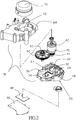
FIG. 2 is an exploded view of the preferred embodiment of the present invention; -
FIG. 3 is a perspective diagram of the base of the preferred embodiment of the present invention; -
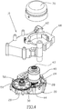
FIG. 4 is an exploded view of the base and the connecting base of the preferred embodiment of the present invention; -
FIG. 5 is a perspective of the base and the connecting base in combination of the preferred embodiment of the present invention; -
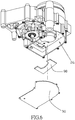
FIG. 6 is an exploded view of the case, the controller, and the lid of the preferred embodiment of the present invention; and -
FIG. 7 is a perspective of the case, the controller, and the lid in combination of the preferred embodiment of the present invention. - As shown in
FIG. 1 , a power assembly of an electric scooter includes acase 10, in which anelectric motor 40, a drivengear 50, and acontroller 80 are received. - As shown in
FIG. 2 andFIG. 3 , thecase 10 has abase 20, in which a separatinglayer 22 is provided to divide a space in thebase 20 into afirst space 24 and asecond space 26. Thefirst space 24 is divided into afirst gear room 28 and asecond gear room 30, and the first and thesecond gear rooms base 20 is provided with a firstaxial bore 32 communicated with thefirst gear room 28, and a secondaxial bore 34 communicated with thesecond gear room 34, and both the first and the secondaxial bores - As shown in
FIG. 2 andFIG. 4 , theelectric motor 40 has anoutput shaft 42 and adriving gear 44 fixed to theoutput shaft 42. Theelectric motor 40 is mounted in thecase 10 with thedriving gear 44 in thefirst gear room 28 of thefirst space 24 of thebase 20 and theoutput shaft 42 passing through the firstaxial bore 32. - The driven
gear 50 is fixed to agear shaft 52, wherein the drivengear 50 is received in thesecond gear room 30 of thefirst space 24 to mesh with thedriving gear 44, and thegear shaft 52 extends out of thecase 10 through the secondaxial bore 34. - As shown in
FIGS. 2 ,4 , and5 , thecase 10 further has a connectingbase 60 to be coupled to thebase 20 at a side with thefirst space 24. The connectingbase 60 is provided with athrough hole 62 for theelectric motor 40 passing through. Thecase 10 further has alid 70 coupled to the connectingbase 60 to cover theelectric motor 40 and seal the throughhole 62. Thegear shaft 52 is pivoted on the connectingbase 60. - As shown in
FIG. 2 andFIG. 6 , thecontroller 80 is mounted in thesecond space 26 of thebase 20 and electrical connected to the electric motor. Thecase 10 further has acover 90 coupled to thebase 20 at a side with thesecond space 26 to seal thesecond space 26. - As shown in
FIG. 7 , ashaft lid 92 is received in thesecond space 26 and fixed to thebase 20 to cover theoutput shaft 42 of theelectric motor 40 and seal the firstaxial bore 32. Thecontroller 80 is beside theshaft lid 92. Abearing 100 is provided on an interior side of thelid 70, and abearing 102 is provided in the firstaxial bore 32. Both thebearings output shaft 42 of theelectric motor 40 to make theoutput shaft 42 stably turn. Abearing 104 is provided in the secondaxial bore 34, and abearing 106 is provided on the connectingbase 60. Both thebearings gear shaft 52 of the drivengear 50 to make the drivengear 50 stably turn. A pulley 110 is connected to thegear shaft 52 and left out of thecase 10 to transmit the power of theelectric motor 40 out. - The present invention integrates the
electric motor 40, the drivengear 50, and thecontroller 80 in thecase 10, so that the size of the present invention is smaller than the prior art. In addition, wires (not shown), which electrically connected thecontroller 80 and theelectric motor 40 will run in thecase 10 to make the assembling task easier. - It must be pointed out that the embodiments described above are only some preferred embodiments of the present invention. All equivalent structures which employ the concepts disclosed in this specification and the appended claims should fall within the scope of the present invention.
Claims (7)
- A power assembly of an electric scooter, comprising:a case (10) having a base (20), wherein the base (20) is provided with a separating layer (22) to divide a space in the base (20) into a first space (24) and a second space (26);an electric motor (40), which is provided in the case (10), having an output shaft (42) and a driving gear (44) connected to the output shaft (42), wherein the driving gear (44) is received in the first space (24) of the base (20);a driven gear (50), which is received in the first space (24) of the base (20) and meshed with the driving gear (44), wherein a gear shaft (52) is connected to the driven gear (50), and the gear shaft (52) has an end extending out of the case (10); anda controller (80) provided in the second space (26) of the base (20) and electrically connected to the electric motor (40).
- The power assembly of the electric scooter of claim 1, wherein the first space (24) is divided into a first gear room (28) and a second gear room (30); the driving gear (44) of the electric motor (40) is received in the first gear room (28), and the driven gear (50) is received in the second gear room (30).
- The power assembly of the electric scooter of claim 2, wherein the base (20) is provided with a first axial bore (32) communicated with the first gear room (28) and a second axial bore (32) communicated with the second gear room (30); the output shaft (42) of the electric motor (40) passes through the first axial bore (32), and the gear shaft of the driven gear (50) passes through the second axial bore (32).
- The power assembly of the electric scooter of claim 3, further comprising a shaft lid (92) received in the second space (26) of the base (20) and fixed to the base (20) to cover the output shaft (42) of the electric motor (40), wherein the output shaft (42) is pivoted on the shaft lid (92).
- The power assembly of the electric scooter of claim 1, further comprising a cover (90) coupled to the base (20) to seal the second space (26).
- The power assembly of the electric scooter of claim 1, wherein the case further includes a connecting base (60) coupled to the base (20) at a side of the first space (24); the connecting base (60) is provided with a through hole (62) for the electric motor (40) passing through.
- The power assembly of the electric scooter of claim 6, further comprising a lid (70) coupled to the connecting base (60) to cover the electric motor (40) and seal the through hole (62).
Priority Applications (2)
| Application Number | Priority Date | Filing Date | Title |
|---|---|---|---|
| ES18188270T ES2881082T3 (en) | 2018-08-09 | 2018-08-09 | Power set for electric scooter |
| EP18188270.5A EP3608176B1 (en) | 2018-08-09 | 2018-08-09 | Power assembly of electric scooter |
Applications Claiming Priority (1)
| Application Number | Priority Date | Filing Date | Title |
|---|---|---|---|
| EP18188270.5A EP3608176B1 (en) | 2018-08-09 | 2018-08-09 | Power assembly of electric scooter |
Publications (2)
| Publication Number | Publication Date |
|---|---|
| EP3608176A1 true EP3608176A1 (en) | 2020-02-12 |
| EP3608176B1 EP3608176B1 (en) | 2021-06-02 |
Family
ID=63490153
Family Applications (1)
| Application Number | Title | Priority Date | Filing Date |
|---|---|---|---|
| EP18188270.5A Active EP3608176B1 (en) | 2018-08-09 | 2018-08-09 | Power assembly of electric scooter |
Country Status (2)
| Country | Link |
|---|---|
| EP (1) | EP3608176B1 (en) |
| ES (1) | ES2881082T3 (en) |
Citations (6)
| Publication number | Priority date | Publication date | Assignee | Title |
|---|---|---|---|---|
| JP2006353045A (en) * | 2005-06-20 | 2006-12-28 | Matsushita Electric Ind Co Ltd | Electric bicycle |
| US20110290578A1 (en) * | 2010-05-28 | 2011-12-01 | Honda Motor Co., Ltd. | Saddle riding type, electric vehicle |
| CN204915979U (en) * | 2015-07-01 | 2015-12-30 | 浙江易力车业有限公司 | Double round electric scooter |
| CN106143777A (en) * | 2015-04-22 | 2016-11-23 | 苏州赛诺伊电动科技有限公司 | A kind of Moped Scooter built-in motor and moment measuring device thereof |
| US20170314643A1 (en) * | 2016-04-28 | 2017-11-02 | Lear Corporation | Actuator Assembly |
| US20170373558A1 (en) * | 2016-06-23 | 2017-12-28 | Molon Motor And Coil Corporation | Dual Compartment Gear Motor Assembly |
-
2018
- 2018-08-09 ES ES18188270T patent/ES2881082T3/en active Active
- 2018-08-09 EP EP18188270.5A patent/EP3608176B1/en active Active
Patent Citations (6)
| Publication number | Priority date | Publication date | Assignee | Title |
|---|---|---|---|---|
| JP2006353045A (en) * | 2005-06-20 | 2006-12-28 | Matsushita Electric Ind Co Ltd | Electric bicycle |
| US20110290578A1 (en) * | 2010-05-28 | 2011-12-01 | Honda Motor Co., Ltd. | Saddle riding type, electric vehicle |
| CN106143777A (en) * | 2015-04-22 | 2016-11-23 | 苏州赛诺伊电动科技有限公司 | A kind of Moped Scooter built-in motor and moment measuring device thereof |
| CN204915979U (en) * | 2015-07-01 | 2015-12-30 | 浙江易力车业有限公司 | Double round electric scooter |
| US20170314643A1 (en) * | 2016-04-28 | 2017-11-02 | Lear Corporation | Actuator Assembly |
| US20170373558A1 (en) * | 2016-06-23 | 2017-12-28 | Molon Motor And Coil Corporation | Dual Compartment Gear Motor Assembly |
Also Published As
| Publication number | Publication date |
|---|---|
| EP3608176B1 (en) | 2021-06-02 |
| ES2881082T3 (en) | 2021-11-26 |
Similar Documents
| Publication | Publication Date | Title |
|---|---|---|
| DE102008020144B4 (en) | power tool | |
| CN106763515B (en) | Steering engine | |
| US20200047848A1 (en) | Power assembly of electric scooter | |
| US11313451B2 (en) | Compact electric linear drive for a gear rack, in particular a hydraulic valve, and method for mounting the same | |
| WO2019038564A3 (en) | Vehicle, vehicle chassis and drivetrain module | |
| EP3480924B1 (en) | Speed reducing device having power source | |
| WO2010024021A1 (en) | Electric compressor | |
| US10047827B2 (en) | Low-profile, rotating-shaft transmission device, and associated method | |
| US10647191B2 (en) | Transmission for a motor vehicle | |
| CN106369117B (en) | A kind of speed adjusting gear | |
| US4601643A (en) | Rotary compressor machines | |
| EP3608176A1 (en) | Power assembly of electric scooter | |
| CN206582286U (en) | a steering gear | |
| DE102015214785B3 (en) | Electric compressor | |
| KR20090127601A (en) | Reducer Integral Motor Assembly | |
| CN219570328U (en) | Integrated end shell for electronic oil pump | |
| JP3223123U (en) | Power assembly parts for electric motorcycles | |
| CN107255073A (en) | A kind of electric motor built-in gear pump | |
| US11859694B2 (en) | Linear actuator and linear actuator assembling method | |
| CN216634362U (en) | Stable output actuator, mechanical arm and robot | |
| CN110715027B (en) | Power assembly of electric locomotive | |
| CN108638075A (en) | A kind of steering engine | |
| KR101154035B1 (en) | Servo motor assembly having multiple concentric output shaft | |
| JP2018064405A (en) | Geared motor | |
| JPWO2018025378A1 (en) | Electric drive |
Legal Events
| Date | Code | Title | Description |
|---|---|---|---|
| STAA | Information on the status of an ep patent application or granted ep patent |
Free format text: STATUS: EXAMINATION IS IN PROGRESS |
|
| PUAI | Public reference made under article 153(3) epc to a published international application that has entered the european phase |
Free format text: ORIGINAL CODE: 0009012 |
|
| 17P | Request for examination filed |
Effective date: 20190718 |
|
| AK | Designated contracting states |
Kind code of ref document: A1 Designated state(s): AL AT BE BG CH CY CZ DE DK EE ES FI FR GB GR HR HU IE IS IT LI LT LU LV MC MK MT NL NO PL PT RO RS SE SI SK SM TR |
|
| AX | Request for extension of the european patent |
Extension state: BA ME |
|
| GRAP | Despatch of communication of intention to grant a patent |
Free format text: ORIGINAL CODE: EPIDOSNIGR1 |
|
| STAA | Information on the status of an ep patent application or granted ep patent |
Free format text: STATUS: GRANT OF PATENT IS INTENDED |
|
| INTG | Intention to grant announced |
Effective date: 20210125 |
|
| GRAS | Grant fee paid |
Free format text: ORIGINAL CODE: EPIDOSNIGR3 |
|
| GRAA | (expected) grant |
Free format text: ORIGINAL CODE: 0009210 |
|
| STAA | Information on the status of an ep patent application or granted ep patent |
Free format text: STATUS: THE PATENT HAS BEEN GRANTED |
|
| REG | Reference to a national code |
Ref country code: CH Ref legal event code: EP |
|
| AK | Designated contracting states |
Kind code of ref document: B1 Designated state(s): AL AT BE BG CH CY CZ DE DK EE ES FI FR GB GR HR HU IE IS IT LI LT LU LV MC MK MT NL NO PL PT RO RS SE SI SK SM TR |
|
| REG | Reference to a national code |
Ref country code: GB Ref legal event code: FG4D |
|
| REG | Reference to a national code |
Ref country code: AT Ref legal event code: REF Ref document number: 1398167 Country of ref document: AT Kind code of ref document: T Effective date: 20210615 |
|
| REG | Reference to a national code |
Ref country code: IE Ref legal event code: FG4D |
|
| REG | Reference to a national code |
Ref country code: DE Ref legal event code: R096 Ref document number: 602018017915 Country of ref document: DE |
|
| REG | Reference to a national code |
Ref country code: NL Ref legal event code: FP |
|
| REG | Reference to a national code |
Ref country code: LT Ref legal event code: MG9D |
|
| PG25 | Lapsed in a contracting state [announced via postgrant information from national office to epo] |
Ref country code: BG Free format text: LAPSE BECAUSE OF FAILURE TO SUBMIT A TRANSLATION OF THE DESCRIPTION OR TO PAY THE FEE WITHIN THE PRESCRIBED TIME-LIMIT Effective date: 20210902 Ref country code: HR Free format text: LAPSE BECAUSE OF FAILURE TO SUBMIT A TRANSLATION OF THE DESCRIPTION OR TO PAY THE FEE WITHIN THE PRESCRIBED TIME-LIMIT Effective date: 20210602 Ref country code: LT Free format text: LAPSE BECAUSE OF FAILURE TO SUBMIT A TRANSLATION OF THE DESCRIPTION OR TO PAY THE FEE WITHIN THE PRESCRIBED TIME-LIMIT Effective date: 20210602 Ref country code: FI Free format text: LAPSE BECAUSE OF FAILURE TO SUBMIT A TRANSLATION OF THE DESCRIPTION OR TO PAY THE FEE WITHIN THE PRESCRIBED TIME-LIMIT Effective date: 20210602 |
|
| REG | Reference to a national code |
Ref country code: AT Ref legal event code: MK05 Ref document number: 1398167 Country of ref document: AT Kind code of ref document: T Effective date: 20210602 |
|
| REG | Reference to a national code |
Ref country code: ES Ref legal event code: FG2A Ref document number: 2881082 Country of ref document: ES Kind code of ref document: T3 Effective date: 20211126 |
|
| PG25 | Lapsed in a contracting state [announced via postgrant information from national office to epo] |
Ref country code: GR Free format text: LAPSE BECAUSE OF FAILURE TO SUBMIT A TRANSLATION OF THE DESCRIPTION OR TO PAY THE FEE WITHIN THE PRESCRIBED TIME-LIMIT Effective date: 20210903 Ref country code: RS Free format text: LAPSE BECAUSE OF FAILURE TO SUBMIT A TRANSLATION OF THE DESCRIPTION OR TO PAY THE FEE WITHIN THE PRESCRIBED TIME-LIMIT Effective date: 20210602 Ref country code: SE Free format text: LAPSE BECAUSE OF FAILURE TO SUBMIT A TRANSLATION OF THE DESCRIPTION OR TO PAY THE FEE WITHIN THE PRESCRIBED TIME-LIMIT Effective date: 20210602 Ref country code: LV Free format text: LAPSE BECAUSE OF FAILURE TO SUBMIT A TRANSLATION OF THE DESCRIPTION OR TO PAY THE FEE WITHIN THE PRESCRIBED TIME-LIMIT Effective date: 20210602 Ref country code: NO Free format text: LAPSE BECAUSE OF FAILURE TO SUBMIT A TRANSLATION OF THE DESCRIPTION OR TO PAY THE FEE WITHIN THE PRESCRIBED TIME-LIMIT Effective date: 20210902 Ref country code: PL Free format text: LAPSE BECAUSE OF FAILURE TO SUBMIT A TRANSLATION OF THE DESCRIPTION OR TO PAY THE FEE WITHIN THE PRESCRIBED TIME-LIMIT Effective date: 20210602 |
|
| PG25 | Lapsed in a contracting state [announced via postgrant information from national office to epo] |
Ref country code: RO Free format text: LAPSE BECAUSE OF FAILURE TO SUBMIT A TRANSLATION OF THE DESCRIPTION OR TO PAY THE FEE WITHIN THE PRESCRIBED TIME-LIMIT Effective date: 20210602 Ref country code: PT Free format text: LAPSE BECAUSE OF FAILURE TO SUBMIT A TRANSLATION OF THE DESCRIPTION OR TO PAY THE FEE WITHIN THE PRESCRIBED TIME-LIMIT Effective date: 20211004 Ref country code: AT Free format text: LAPSE BECAUSE OF FAILURE TO SUBMIT A TRANSLATION OF THE DESCRIPTION OR TO PAY THE FEE WITHIN THE PRESCRIBED TIME-LIMIT Effective date: 20210602 Ref country code: SM Free format text: LAPSE BECAUSE OF FAILURE TO SUBMIT A TRANSLATION OF THE DESCRIPTION OR TO PAY THE FEE WITHIN THE PRESCRIBED TIME-LIMIT Effective date: 20210602 Ref country code: SK Free format text: LAPSE BECAUSE OF FAILURE TO SUBMIT A TRANSLATION OF THE DESCRIPTION OR TO PAY THE FEE WITHIN THE PRESCRIBED TIME-LIMIT Effective date: 20210602 Ref country code: EE Free format text: LAPSE BECAUSE OF FAILURE TO SUBMIT A TRANSLATION OF THE DESCRIPTION OR TO PAY THE FEE WITHIN THE PRESCRIBED TIME-LIMIT Effective date: 20210602 |
|
| REG | Reference to a national code |
Ref country code: DE Ref legal event code: R097 Ref document number: 602018017915 Country of ref document: DE |
|
| REG | Reference to a national code |
Ref country code: CH Ref legal event code: PL |
|
| PG25 | Lapsed in a contracting state [announced via postgrant information from national office to epo] |
Ref country code: MC Free format text: LAPSE BECAUSE OF FAILURE TO SUBMIT A TRANSLATION OF THE DESCRIPTION OR TO PAY THE FEE WITHIN THE PRESCRIBED TIME-LIMIT Effective date: 20210602 |
|
| PLBE | No opposition filed within time limit |
Free format text: ORIGINAL CODE: 0009261 |
|
| STAA | Information on the status of an ep patent application or granted ep patent |
Free format text: STATUS: NO OPPOSITION FILED WITHIN TIME LIMIT |
|
| REG | Reference to a national code |
Ref country code: BE Ref legal event code: MM Effective date: 20210831 |
|
| PG25 | Lapsed in a contracting state [announced via postgrant information from national office to epo] |
Ref country code: LI Free format text: LAPSE BECAUSE OF NON-PAYMENT OF DUE FEES Effective date: 20210831 Ref country code: DK Free format text: LAPSE BECAUSE OF FAILURE TO SUBMIT A TRANSLATION OF THE DESCRIPTION OR TO PAY THE FEE WITHIN THE PRESCRIBED TIME-LIMIT Effective date: 20210602 Ref country code: CH Free format text: LAPSE BECAUSE OF NON-PAYMENT OF DUE FEES Effective date: 20210831 |
|
| 26N | No opposition filed |
Effective date: 20220303 |
|
| PG25 | Lapsed in a contracting state [announced via postgrant information from national office to epo] |
Ref country code: LU Free format text: LAPSE BECAUSE OF NON-PAYMENT OF DUE FEES Effective date: 20210809 Ref country code: AL Free format text: LAPSE BECAUSE OF FAILURE TO SUBMIT A TRANSLATION OF THE DESCRIPTION OR TO PAY THE FEE WITHIN THE PRESCRIBED TIME-LIMIT Effective date: 20210602 |
|
| PG25 | Lapsed in a contracting state [announced via postgrant information from national office to epo] |
Ref country code: IE Free format text: LAPSE BECAUSE OF NON-PAYMENT OF DUE FEES Effective date: 20210809 Ref country code: BE Free format text: LAPSE BECAUSE OF NON-PAYMENT OF DUE FEES Effective date: 20210831 |
|
| PG25 | Lapsed in a contracting state [announced via postgrant information from national office to epo] |
Ref country code: CY Free format text: LAPSE BECAUSE OF FAILURE TO SUBMIT A TRANSLATION OF THE DESCRIPTION OR TO PAY THE FEE WITHIN THE PRESCRIBED TIME-LIMIT Effective date: 20210602 |
|
| PG25 | Lapsed in a contracting state [announced via postgrant information from national office to epo] |
Ref country code: HU Free format text: LAPSE BECAUSE OF FAILURE TO SUBMIT A TRANSLATION OF THE DESCRIPTION OR TO PAY THE FEE WITHIN THE PRESCRIBED TIME-LIMIT; INVALID AB INITIO Effective date: 20180809 |
|
| PG25 | Lapsed in a contracting state [announced via postgrant information from national office to epo] |
Ref country code: MK Free format text: LAPSE BECAUSE OF FAILURE TO SUBMIT A TRANSLATION OF THE DESCRIPTION OR TO PAY THE FEE WITHIN THE PRESCRIBED TIME-LIMIT Effective date: 20210602 |
|
| PG25 | Lapsed in a contracting state [announced via postgrant information from national office to epo] |
Ref country code: MT Free format text: LAPSE BECAUSE OF FAILURE TO SUBMIT A TRANSLATION OF THE DESCRIPTION OR TO PAY THE FEE WITHIN THE PRESCRIBED TIME-LIMIT Effective date: 20210602 |
|
| PGFP | Annual fee paid to national office [announced via postgrant information from national office to epo] |
Ref country code: NL Payment date: 20250822 Year of fee payment: 8 |
|
| PGFP | Annual fee paid to national office [announced via postgrant information from national office to epo] |
Ref country code: ES Payment date: 20250902 Year of fee payment: 8 |
|
| PGFP | Annual fee paid to national office [announced via postgrant information from national office to epo] |
Ref country code: DE Payment date: 20250827 Year of fee payment: 8 |
|
| PGFP | Annual fee paid to national office [announced via postgrant information from national office to epo] |
Ref country code: IT Payment date: 20250805 Year of fee payment: 8 |
|
| PGFP | Annual fee paid to national office [announced via postgrant information from national office to epo] |
Ref country code: GB Payment date: 20250826 Year of fee payment: 8 |
|
| PGFP | Annual fee paid to national office [announced via postgrant information from national office to epo] |
Ref country code: FR Payment date: 20250819 Year of fee payment: 8 |
|
| PGFP | Annual fee paid to national office [announced via postgrant information from national office to epo] |
Ref country code: CZ Payment date: 20250722 Year of fee payment: 8 |
|
| PG25 | Lapsed in a contracting state [announced via postgrant information from national office to epo] |
Ref country code: TR Free format text: LAPSE BECAUSE OF FAILURE TO SUBMIT A TRANSLATION OF THE DESCRIPTION OR TO PAY THE FEE WITHIN THE PRESCRIBED TIME-LIMIT Effective date: 20210602 |