EP3608146B1 - Flammability resistant visual display assembly - Google Patents
Flammability resistant visual display assembly Download PDFInfo
- Publication number
- EP3608146B1 EP3608146B1 EP19189698.4A EP19189698A EP3608146B1 EP 3608146 B1 EP3608146 B1 EP 3608146B1 EP 19189698 A EP19189698 A EP 19189698A EP 3608146 B1 EP3608146 B1 EP 3608146B1
- Authority
- EP
- European Patent Office
- Prior art keywords
- assembly
- interior
- circuit card
- visual display
- unit
- Prior art date
- Legal status (The legal status is an assumption and is not a legal conclusion. Google has not performed a legal analysis and makes no representation as to the accuracy of the status listed.)
- Not-in-force
Links
Images




Classifications
-
- B—PERFORMING OPERATIONS; TRANSPORTING
- B64—AIRCRAFT; AVIATION; COSMONAUTICS
- B64D—EQUIPMENT FOR FITTING IN OR TO AIRCRAFT; FLIGHT SUITS; PARACHUTES; ARRANGEMENT OR MOUNTING OF POWER PLANTS OR PROPULSION TRANSMISSIONS IN AIRCRAFT
- B64D43/00—Arrangements or adaptations of instruments
-
- B—PERFORMING OPERATIONS; TRANSPORTING
- B60—VEHICLES IN GENERAL
- B60K—ARRANGEMENT OR MOUNTING OF PROPULSION UNITS OR OF TRANSMISSIONS IN VEHICLES; ARRANGEMENT OR MOUNTING OF PLURAL DIVERSE PRIME-MOVERS IN VEHICLES; AUXILIARY DRIVES FOR VEHICLES; INSTRUMENTATION OR DASHBOARDS FOR VEHICLES; ARRANGEMENTS IN CONNECTION WITH COOLING, AIR INTAKE, GAS EXHAUST OR FUEL SUPPLY OF PROPULSION UNITS IN VEHICLES
- B60K35/00—Instruments specially adapted for vehicles; Arrangement of instruments in or on vehicles
- B60K35/20—Output arrangements, i.e. from vehicle to user, associated with vehicle functions or specially adapted therefor
- B60K35/21—Output arrangements, i.e. from vehicle to user, associated with vehicle functions or specially adapted therefor using visual output, e.g. blinking lights or matrix displays
- B60K35/22—Display screens
-
- B—PERFORMING OPERATIONS; TRANSPORTING
- B60—VEHICLES IN GENERAL
- B60K—ARRANGEMENT OR MOUNTING OF PROPULSION UNITS OR OF TRANSMISSIONS IN VEHICLES; ARRANGEMENT OR MOUNTING OF PLURAL DIVERSE PRIME-MOVERS IN VEHICLES; AUXILIARY DRIVES FOR VEHICLES; INSTRUMENTATION OR DASHBOARDS FOR VEHICLES; ARRANGEMENTS IN CONNECTION WITH COOLING, AIR INTAKE, GAS EXHAUST OR FUEL SUPPLY OF PROPULSION UNITS IN VEHICLES
- B60K35/00—Instruments specially adapted for vehicles; Arrangement of instruments in or on vehicles
- B60K35/90—Calibration of instruments, e.g. setting initial or reference parameters; Testing of instruments, e.g. detecting malfunction
-
- B—PERFORMING OPERATIONS; TRANSPORTING
- B60—VEHICLES IN GENERAL
- B60K—ARRANGEMENT OR MOUNTING OF PROPULSION UNITS OR OF TRANSMISSIONS IN VEHICLES; ARRANGEMENT OR MOUNTING OF PLURAL DIVERSE PRIME-MOVERS IN VEHICLES; AUXILIARY DRIVES FOR VEHICLES; INSTRUMENTATION OR DASHBOARDS FOR VEHICLES; ARRANGEMENTS IN CONNECTION WITH COOLING, AIR INTAKE, GAS EXHAUST OR FUEL SUPPLY OF PROPULSION UNITS IN VEHICLES
- B60K37/00—Dashboards
- B60K37/20—Dashboard panels
-
- G—PHYSICS
- G02—OPTICS
- G02F—OPTICAL DEVICES OR ARRANGEMENTS FOR THE CONTROL OF LIGHT BY MODIFICATION OF THE OPTICAL PROPERTIES OF THE MEDIA OF THE ELEMENTS INVOLVED THEREIN; NON-LINEAR OPTICS; FREQUENCY-CHANGING OF LIGHT; OPTICAL LOGIC ELEMENTS; OPTICAL ANALOGUE/DIGITAL CONVERTERS
- G02F1/00—Devices or arrangements for the control of the intensity, colour, phase, polarisation or direction of light arriving from an independent light source, e.g. switching, gating or modulating; Non-linear optics
- G02F1/01—Devices or arrangements for the control of the intensity, colour, phase, polarisation or direction of light arriving from an independent light source, e.g. switching, gating or modulating; Non-linear optics for the control of the intensity, phase, polarisation or colour
- G02F1/13—Devices or arrangements for the control of the intensity, colour, phase, polarisation or direction of light arriving from an independent light source, e.g. switching, gating or modulating; Non-linear optics for the control of the intensity, phase, polarisation or colour based on liquid crystals, e.g. single liquid crystal display cells
- G02F1/133—Constructional arrangements; Operation of liquid crystal cells; Circuit arrangements
- G02F1/1333—Constructional arrangements; Manufacturing methods
- G02F1/133308—Support structures for LCD panels, e.g. frames or bezels
-
- G—PHYSICS
- G02—OPTICS
- G02F—OPTICAL DEVICES OR ARRANGEMENTS FOR THE CONTROL OF LIGHT BY MODIFICATION OF THE OPTICAL PROPERTIES OF THE MEDIA OF THE ELEMENTS INVOLVED THEREIN; NON-LINEAR OPTICS; FREQUENCY-CHANGING OF LIGHT; OPTICAL LOGIC ELEMENTS; OPTICAL ANALOGUE/DIGITAL CONVERTERS
- G02F1/00—Devices or arrangements for the control of the intensity, colour, phase, polarisation or direction of light arriving from an independent light source, e.g. switching, gating or modulating; Non-linear optics
- G02F1/01—Devices or arrangements for the control of the intensity, colour, phase, polarisation or direction of light arriving from an independent light source, e.g. switching, gating or modulating; Non-linear optics for the control of the intensity, phase, polarisation or colour
- G02F1/13—Devices or arrangements for the control of the intensity, colour, phase, polarisation or direction of light arriving from an independent light source, e.g. switching, gating or modulating; Non-linear optics for the control of the intensity, phase, polarisation or colour based on liquid crystals, e.g. single liquid crystal display cells
- G02F1/133—Constructional arrangements; Operation of liquid crystal cells; Circuit arrangements
- G02F1/1333—Constructional arrangements; Manufacturing methods
- G02F1/133382—Heating or cooling of liquid crystal cells other than for activation, e.g. circuits or arrangements for temperature control, stabilisation or uniform distribution over the cell
- G02F1/133385—Heating or cooling of liquid crystal cells other than for activation, e.g. circuits or arrangements for temperature control, stabilisation or uniform distribution over the cell with cooling means, e.g. fans
-
- B—PERFORMING OPERATIONS; TRANSPORTING
- B60—VEHICLES IN GENERAL
- B60K—ARRANGEMENT OR MOUNTING OF PROPULSION UNITS OR OF TRANSMISSIONS IN VEHICLES; ARRANGEMENT OR MOUNTING OF PLURAL DIVERSE PRIME-MOVERS IN VEHICLES; AUXILIARY DRIVES FOR VEHICLES; INSTRUMENTATION OR DASHBOARDS FOR VEHICLES; ARRANGEMENTS IN CONNECTION WITH COOLING, AIR INTAKE, GAS EXHAUST OR FUEL SUPPLY OF PROPULSION UNITS IN VEHICLES
- B60K2360/00—Indexing scheme associated with groups B60K35/00 or B60K37/00 relating to details of instruments or dashboards
- B60K2360/1523—Matrix displays
-
- B—PERFORMING OPERATIONS; TRANSPORTING
- B60—VEHICLES IN GENERAL
- B60K—ARRANGEMENT OR MOUNTING OF PROPULSION UNITS OR OF TRANSMISSIONS IN VEHICLES; ARRANGEMENT OR MOUNTING OF PLURAL DIVERSE PRIME-MOVERS IN VEHICLES; AUXILIARY DRIVES FOR VEHICLES; INSTRUMENTATION OR DASHBOARDS FOR VEHICLES; ARRANGEMENTS IN CONNECTION WITH COOLING, AIR INTAKE, GAS EXHAUST OR FUEL SUPPLY OF PROPULSION UNITS IN VEHICLES
- B60K2360/00—Indexing scheme associated with groups B60K35/00 or B60K37/00 relating to details of instruments or dashboards
- B60K2360/40—Hardware adaptations for dashboards or instruments
- B60K2360/42—Circuit board features
-
- B—PERFORMING OPERATIONS; TRANSPORTING
- B60—VEHICLES IN GENERAL
- B60K—ARRANGEMENT OR MOUNTING OF PROPULSION UNITS OR OF TRANSMISSIONS IN VEHICLES; ARRANGEMENT OR MOUNTING OF PLURAL DIVERSE PRIME-MOVERS IN VEHICLES; AUXILIARY DRIVES FOR VEHICLES; INSTRUMENTATION OR DASHBOARDS FOR VEHICLES; ARRANGEMENTS IN CONNECTION WITH COOLING, AIR INTAKE, GAS EXHAUST OR FUEL SUPPLY OF PROPULSION UNITS IN VEHICLES
- B60K2360/00—Indexing scheme associated with groups B60K35/00 or B60K37/00 relating to details of instruments or dashboards
- B60K2360/40—Hardware adaptations for dashboards or instruments
- B60K2360/46—Electrical connections
-
- B—PERFORMING OPERATIONS; TRANSPORTING
- B60—VEHICLES IN GENERAL
- B60K—ARRANGEMENT OR MOUNTING OF PROPULSION UNITS OR OF TRANSMISSIONS IN VEHICLES; ARRANGEMENT OR MOUNTING OF PLURAL DIVERSE PRIME-MOVERS IN VEHICLES; AUXILIARY DRIVES FOR VEHICLES; INSTRUMENTATION OR DASHBOARDS FOR VEHICLES; ARRANGEMENTS IN CONNECTION WITH COOLING, AIR INTAKE, GAS EXHAUST OR FUEL SUPPLY OF PROPULSION UNITS IN VEHICLES
- B60K2360/00—Indexing scheme associated with groups B60K35/00 or B60K37/00 relating to details of instruments or dashboards
- B60K2360/60—Structural details of dashboards or instruments
- B60K2360/68—Features of instruments
- B60K2360/688—Frames or decorative parts
-
- B—PERFORMING OPERATIONS; TRANSPORTING
- B60—VEHICLES IN GENERAL
- B60K—ARRANGEMENT OR MOUNTING OF PROPULSION UNITS OR OF TRANSMISSIONS IN VEHICLES; ARRANGEMENT OR MOUNTING OF PLURAL DIVERSE PRIME-MOVERS IN VEHICLES; AUXILIARY DRIVES FOR VEHICLES; INSTRUMENTATION OR DASHBOARDS FOR VEHICLES; ARRANGEMENTS IN CONNECTION WITH COOLING, AIR INTAKE, GAS EXHAUST OR FUEL SUPPLY OF PROPULSION UNITS IN VEHICLES
- B60K2360/00—Indexing scheme associated with groups B60K35/00 or B60K37/00 relating to details of instruments or dashboards
- B60K2360/60—Structural details of dashboards or instruments
- B60K2360/68—Features of instruments
- B60K2360/691—Housings
-
- B—PERFORMING OPERATIONS; TRANSPORTING
- B60—VEHICLES IN GENERAL
- B60K—ARRANGEMENT OR MOUNTING OF PROPULSION UNITS OR OF TRANSMISSIONS IN VEHICLES; ARRANGEMENT OR MOUNTING OF PLURAL DIVERSE PRIME-MOVERS IN VEHICLES; AUXILIARY DRIVES FOR VEHICLES; INSTRUMENTATION OR DASHBOARDS FOR VEHICLES; ARRANGEMENTS IN CONNECTION WITH COOLING, AIR INTAKE, GAS EXHAUST OR FUEL SUPPLY OF PROPULSION UNITS IN VEHICLES
- B60K2360/00—Indexing scheme associated with groups B60K35/00 or B60K37/00 relating to details of instruments or dashboards
- B60K2360/60—Structural details of dashboards or instruments
- B60K2360/68—Features of instruments
- B60K2360/693—Cover plate features
-
- B—PERFORMING OPERATIONS; TRANSPORTING
- B60—VEHICLES IN GENERAL
- B60Y—INDEXING SCHEME RELATING TO ASPECTS CROSS-CUTTING VEHICLE TECHNOLOGY
- B60Y2200/00—Type of vehicle
- B60Y2200/50—Aeroplanes, Helicopters
-
- G—PHYSICS
- G02—OPTICS
- G02F—OPTICAL DEVICES OR ARRANGEMENTS FOR THE CONTROL OF LIGHT BY MODIFICATION OF THE OPTICAL PROPERTIES OF THE MEDIA OF THE ELEMENTS INVOLVED THEREIN; NON-LINEAR OPTICS; FREQUENCY-CHANGING OF LIGHT; OPTICAL LOGIC ELEMENTS; OPTICAL ANALOGUE/DIGITAL CONVERTERS
- G02F1/00—Devices or arrangements for the control of the intensity, colour, phase, polarisation or direction of light arriving from an independent light source, e.g. switching, gating or modulating; Non-linear optics
- G02F1/01—Devices or arrangements for the control of the intensity, colour, phase, polarisation or direction of light arriving from an independent light source, e.g. switching, gating or modulating; Non-linear optics for the control of the intensity, phase, polarisation or colour
- G02F1/13—Devices or arrangements for the control of the intensity, colour, phase, polarisation or direction of light arriving from an independent light source, e.g. switching, gating or modulating; Non-linear optics for the control of the intensity, phase, polarisation or colour based on liquid crystals, e.g. single liquid crystal display cells
- G02F1/133—Constructional arrangements; Operation of liquid crystal cells; Circuit arrangements
- G02F1/1333—Constructional arrangements; Manufacturing methods
- G02F1/133308—Support structures for LCD panels, e.g. frames or bezels
- G02F1/133314—Back frames
-
- G—PHYSICS
- G02—OPTICS
- G02F—OPTICAL DEVICES OR ARRANGEMENTS FOR THE CONTROL OF LIGHT BY MODIFICATION OF THE OPTICAL PROPERTIES OF THE MEDIA OF THE ELEMENTS INVOLVED THEREIN; NON-LINEAR OPTICS; FREQUENCY-CHANGING OF LIGHT; OPTICAL LOGIC ELEMENTS; OPTICAL ANALOGUE/DIGITAL CONVERTERS
- G02F1/00—Devices or arrangements for the control of the intensity, colour, phase, polarisation or direction of light arriving from an independent light source, e.g. switching, gating or modulating; Non-linear optics
- G02F1/01—Devices or arrangements for the control of the intensity, colour, phase, polarisation or direction of light arriving from an independent light source, e.g. switching, gating or modulating; Non-linear optics for the control of the intensity, phase, polarisation or colour
- G02F1/13—Devices or arrangements for the control of the intensity, colour, phase, polarisation or direction of light arriving from an independent light source, e.g. switching, gating or modulating; Non-linear optics for the control of the intensity, phase, polarisation or colour based on liquid crystals, e.g. single liquid crystal display cells
- G02F1/133—Constructional arrangements; Operation of liquid crystal cells; Circuit arrangements
- G02F1/1333—Constructional arrangements; Manufacturing methods
- G02F1/133308—Support structures for LCD panels, e.g. frames or bezels
- G02F1/13332—Front frames
-
- G—PHYSICS
- G02—OPTICS
- G02F—OPTICAL DEVICES OR ARRANGEMENTS FOR THE CONTROL OF LIGHT BY MODIFICATION OF THE OPTICAL PROPERTIES OF THE MEDIA OF THE ELEMENTS INVOLVED THEREIN; NON-LINEAR OPTICS; FREQUENCY-CHANGING OF LIGHT; OPTICAL LOGIC ELEMENTS; OPTICAL ANALOGUE/DIGITAL CONVERTERS
- G02F2201/00—Constructional arrangements not provided for in groups G02F1/00 - G02F7/00
- G02F2201/50—Protective arrangements
Definitions
- the present invention generally relates to electronic assemblies and more particularly relates to liquid crystal and other visual display assemblies for use in vehicles such as aircraft.
- Electronic assemblies serve a variety of purposes and include a wide array of components for carrying out the functions needed of the assembly.
- visual displays such as liquid crystal displays, that often include touch screen capability and are routinely used in place of analog displays and to replace traditional control mechanisms such as buttons, dials and switches to provide inputs to controlled systems.
- touch screen visual displays may be used in an automobile to control a navigation system or in aircraft to control communication systems, navigation systems, flight control systems, etc.
- Electronic assemblies often have elements that are flammable when exposed to flame during testing or other conditions that could lead to ignition.
- the assembly may include reflectors, brightness enhancement films, dual brightness enhancement films, polarizers, etc.
- DO-160 - Environmental Conditions and Test Procedures for Airborne Equipment is a standard that includes environmental testing procedures for avionics hardware, including for flammability. In the event that these materials are exposed to flame during testing, containing any resulting combustion to prevent spread or for self-extinguishment is generally desirable. Fabrication of visual display systems that are capable of containing internal combustion under these and realworld conditions is complicated and leads to relatively heavy devices.
- US2014/368769 discloses an LED assembly including a supporting layer; LED chips arranged on a first surface of the supporting layer and spaced apart from each other; a coating layer formed over the LED chips and including a fluorescent substance, wherein the coating layer changes light emitted from the LED chips into a linear light source; and an electrode pattern layer formed on a second surface of the supporting layer and in selectively removed regions of the supporting layer and contacting the LED chips.
- an electronic unit defines an interior and includes a circuit card assembly disposed in the interior.
- An enclosure surrounds five sides of the interior.
- a sixth side of the interior is closed by a circuit card assembly.
- the circuit card assembly is coated with a metal layer configured to contain flame within the interior.
- a visual display assembly for an instrument panel includes a front unit defining a first interior.
- a visual display panel has a transparent substantially non-flammable surface and is disposed on a first side of the visual display panel.
- a circuit card assembly is disposed on a second side of the visual display panel.
- a bezel surrounds four sides of the visual display panel.
- a rear unit defines a second interior and includes a case with five substantially closed sides and an open side that faces the front unit. Electronic devices are contained in the second interior and are coupled with the circuit card assembly.
- the front and rear units are disposed adjacent each other, with the circuit card assembly facing the open side.
- the circuit card assembly separates the first interior from the second interior and is coated with a metal layer to inhibit flame propagation between the first and second interiors and to contain flame within the first interior.
- a visual display assembly includes a front unit defining an interior space.
- the front unit includes visual display panel with a transparent panel disposed on its front viewing side.
- the transparent panel is made of a material that resists combustion.
- a circuit card assembly is disposed behind the visual display panel.
- a metal bezel surrounding four sides of the visual display panel and the circuit card assembly.
- a rear unit defines another interior space behind the front unit.
- the rear unit includes a case with five substantially closed sides and one open side that faces the front unit.
- the open side is open in the sense that it is not closed by a metal wall, until assembly to the front unit.
- Various electronic devices are contained in the interior of the rear unit and are coupled with the circuit card assembly.
- the front and rear units are assembled together, and the circuit card assembly faces into the one open side of the rear unit.
- the circuit card assembly is configured to separate the front and rear interiors and is coated with a metal on its rear surface to inhibit combustion propagation between the interiors and to contain any occurring combustion within the front unit.
- FIG. 1 a fragmentary perspective view illustrates the inside of an exemplary aircraft cockpit 20.
- the teachings herein pertain to visual display assemblies used in any type of vehicle including, but not limited to, land-based vehicles such as automobiles and trains as well as watercraft and spacecraft. Additionally, the teachings herein are not limited to vehicle applications. Rather, the teachings herein may also be used with displays that are employed in stationary applications such as information kiosks and automatic teller machines as well as with touch screen displays that are hand held or otherwise not mounted to a surface.
- Aircraft cockpit 20 includes an instrument panel 22 positioned to be accessible from a pilot seat 24 and a copilot seat 26.
- Instrument panel 22 includes various electronic units such as readouts 28 and various control features such as buttons 30, switches 32, throttle controls 34, and yokes 36.
- electronic units in the form of visual display assemblies 36-41 are also mounted on or in instrument panel 22.
- the visual display assemblies 36-41 deliver information about the aircraft and may include touch capability to receive inputs.
- a touch capable visual display assembly 36-41 may be configured to control landing gear deployment, flight control surface actuation, or radio and navigation system operations.
- the electronic units of various types may include an enclosure 43 that surrounds five sides of an interior 45.
- the enclosure 43 may be constructed of metal or another flame-resistant material.
- a circuit card assembly 47 is disposed at least partially in the interior 45, or at an edge of the interior 45.
- a sixth side of the interior 45 is closed by the circuit card assembly 47.
- the circuit card assembly 47 is coated with a metal layer 49 configured to contain flame within the interior 45.
- the interior 45 contains internal componentry 55 that is flammable and may combust when exposed to flame.
- the enclosure 43 and the metal layer 49 provide a flame-resistant unit, which in the event of combustion of the internal componentry 55, contains the combustion from spreading outside the interior 45.
- Visual display assembly 36 includes a front unit 42 with a display panel in the form of a liquid crystal display screen 44, that has a transparent front surface 46 through which information is displayed and that faces into the cockpit 20.
- the front surface 46 is part of a layer made of glass, flame retardant polycarbonate, or another flame-resistant material.
- the liquid crystal display screen 44 is surrounded or framed on four sides by bezel 50, which is made of metal, such as aluminum, or other material.
- the bezel 50 closes four sides 51-54 of the front unit 42.
- the bezel 50 includes an extension 56 that extends around all four sides 51-54, which is also made of metal and may be an integral part of the bezel 50 or a separate connected piece.
- the front unit 42 includes internal componentry 58 that may include, for example, light guide plates, reflector films, diffusers and other components or films. These items of the internal componentry 58 may be made of polymers such as Polystyrene, Acrylic, etc. These plastics may combust when exposed to flame and therefore, when subjected to flame under DO-160 testing may ignite.
- a circuit card assembly (CCA) 60 is positioned behind the internal componentry 58 and engages the sides 51-54 closing the opening 62 that would otherwise exist at the rear 64 of the front unit 42.
- the CCA 60 includes a substrate 68 formed from a composite that contains a matrix (such as an epoxy resin) and a reinforcement (such as woven glass fibers).
- the rear side 70 of the substrate 68 is coated with a metal layer 72, made of a material such as copper, tin, aluminum, or another metal.
- the metal layer 72 may be applied by deposition, adhesive, fastening, or other techniques.
- the metal layer 72 serves as the sixth aside of the enclosure 74 for the front unit and is continuous over the rear side 70 of the CCA 60, except at the connectors 78, 80.
- the enclosure 74 includes the front surface 46 of the transparent layer, the four sides 51-54 and the metal layer 72. In the case of exposure to flame, any combustion of the internal componentry 58 is thereby contained by the enclosure 74 and will burn out or selfextinguish under containment.
- Forming the metal layer 72 on the CCA 60 provides for a lighter weight and readily assembled visual display assembly 36.
- the metal layer 72 does not restrict the ability to locate connection points on the CCA 60, such as those required to connect with a rear unit 76, for example at mating connectors 78, 80.
- the rear unit 76 includes a case 79, that includes four sides 81-84, corresponding to the sides 51-54.
- a rear plate 86 forms a fifth side at the rear of the rear unit 76.
- Electronic devices including a set of three printed CCAs 87, 88, 89 are carried within the rear unit 76.
- the CCA 87 is configured to connect with the connectors 78, 80 and carries a heat sink 90.
- the CCA 89 includes a connector 91 that extends through an opening 92 in the rear plate 86 to connect the visual display assembly 36 with systems of the aircraft.
- the rear unit 76 generates heat and so the case 82 includes vent holes 94, the rear plate 86 includes vent holes 96, and the rear plate 86 carries a fan 98 for circulating ventilation air through the rear unit 76.
- the interior of the front unit 42 is separated from the ventilation by the CCA 60 and the metal layer 72.
- the rear unit includes internal components that are non-flammable or self-extinguishing. Accordingly, separation of the internal componentry 58 in the front unit 50 from the rear unit 76 is needed to provide flammability resistance for the internal componentry 58 of the front unit 50. This separation is accomplished by the metal layer 72.
- flammability resistance is accomplished through a complete enclosure of a visual display assembly's front unit by a four-sided metal bezel, a glass front surface/layer and a rear CCA coated with metal.
Landscapes
- Engineering & Computer Science (AREA)
- Physics & Mathematics (AREA)
- Chemical & Material Sciences (AREA)
- Nonlinear Science (AREA)
- Mechanical Engineering (AREA)
- Transportation (AREA)
- Combustion & Propulsion (AREA)
- Mathematical Physics (AREA)
- Crystallography & Structural Chemistry (AREA)
- General Physics & Mathematics (AREA)
- Optics & Photonics (AREA)
- Aviation & Aerospace Engineering (AREA)
- Devices For Indicating Variable Information By Combining Individual Elements (AREA)
- Instrument Panels (AREA)
- Thermal Sciences (AREA)
- Microelectronics & Electronic Packaging (AREA)
Description
- The present invention generally relates to electronic assemblies and more particularly relates to liquid crystal and other visual display assemblies for use in vehicles such as aircraft.
- Electronic assemblies serve a variety of purposes and include a wide array of components for carrying out the functions needed of the assembly. One example involves visual displays such as liquid crystal displays, that often include touch screen capability and are routinely used in place of analog displays and to replace traditional control mechanisms such as buttons, dials and switches to provide inputs to controlled systems. One area where visual displays are increasingly being used is in vehicles to provide information for controlling and monitoring various subsystems of those vehicles. For example, touch screen visual displays may be used in an automobile to control a navigation system or in aircraft to control communication systems, navigation systems, flight control systems, etc.
- Electronic assemblies often have elements that are flammable when exposed to flame during testing or other conditions that could lead to ignition. In the case of visual displays, the assembly may include reflectors, brightness enhancement films, dual brightness enhancement films, polarizers, etc. In one application, DO-160 - Environmental Conditions and Test Procedures for Airborne Equipment, is a standard that includes environmental testing procedures for avionics hardware, including for flammability. In the event that these materials are exposed to flame during testing, containing any resulting combustion to prevent spread or for self-extinguishment is generally desirable. Fabrication of visual display systems that are capable of containing internal combustion under these and realworld conditions is complicated and leads to relatively heavy devices.
- Accordingly, it is desirable to manufacture a visual display system designed for flammability resistance that has improved manufacturability and lower weight. Furthermore, other desirable features and characteristics of the inventive subject matter will become apparent from the subsequent detailed description of the inventive subject matter and the appended claims, taken in conjunction with the accompanying drawings and this background of the inventive subject matter.
US2014/368769 discloses an LED assembly including a supporting layer; LED chips arranged on a first surface of the supporting layer and spaced apart from each other; a coating layer formed over the LED chips and including a fluorescent substance, wherein the coating layer changes light emitted from the LED chips into a linear light source; and an electrode pattern layer formed on a second surface of the supporting layer and in selectively removed regions of the supporting layer and contacting the LED chips. - In an aspect of the invention according to claim 1, an electronic unit defines an interior and includes a circuit card assembly disposed in the interior. An enclosure surrounds five sides of the interior. A sixth side of the interior is closed by a circuit card assembly. The circuit card assembly is coated with a metal layer configured to contain flame within the interior.
- In an aspect according to the invention according to claim 12, a visual display assembly for an instrument panel includes a front unit defining a first interior. A visual display panel has a transparent substantially non-flammable surface and is disposed on a first side of the visual display panel. A circuit card assembly is disposed on a second side of the visual display panel. A bezel surrounds four sides of the visual display panel. A rear unit defines a second interior and includes a case with five substantially closed sides and an open side that faces the front unit. Electronic devices are contained in the second interior and are coupled with the circuit card assembly. The front and rear units are disposed adjacent each other, with the circuit card assembly facing the open side. The circuit card assembly separates the first interior from the second interior and is coated with a metal layer to inhibit flame propagation between the first and second interiors and to contain flame within the first interior.
- The present invention will hereinafter be described in conjunction with the following drawing figures, wherein like numerals denote like elements, and wherein:
-
FIG. 1 is a fragmentary perspective view illustrating the inside of an aircraft viewing the cockpit area, in accordance with an exemplary embodiment; -
FIG. 2 is a schematic cross-sectional illustration of an electronic unit, in accordance with an exemplary embodiment; -
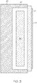
FIG. 3 is a schematic cross-sectional illustration of an electronic unit in the form of a visual display system, in accordance with an exemplary embodiment; -
FIG. 4 is a partially exploded view of a front unit of the visual display system ofFIG. 3 , in accordance with an exemplary embodiment; and -
FIG. 5 is an exploded view of the visual display system, in accordance with an exemplary embodiment. - Embodiments of a visual display assembly are disclosed herein that are constructed to contain any combustion that may occur, including testing induced combustion. As noted above, during environmental testing, visual display assemblies may be exposed to flame to evaluate their response. In an example described further below, a visual display assembly includes a front unit defining an interior space. The front unit includes visual display panel with a transparent panel disposed on its front viewing side. The transparent panel is made of a material that resists combustion. A circuit card assembly is disposed behind the visual display panel. A metal bezel surrounding four sides of the visual display panel and the circuit card assembly. A rear unit defines another interior space behind the front unit. The rear unit includes a case with five substantially closed sides and one open side that faces the front unit. The open side is open in the sense that it is not closed by a metal wall, until assembly to the front unit. Various electronic devices are contained in the interior of the rear unit and are coupled with the circuit card assembly. The front and rear units are assembled together, and the circuit card assembly faces into the one open side of the rear unit. The circuit card assembly is configured to separate the front and rear interiors and is coated with a metal on its rear surface to inhibit combustion propagation between the interiors and to contain any occurring combustion within the front unit.
- Referring to
FIG. 1 , a fragmentary perspective view illustrates the inside of anexemplary aircraft cockpit 20. Although the context of the current disclosure is directed to visual display assemblies used in aircraft, it should be understood that the teachings herein pertain to visual display assemblies used in any type of vehicle including, but not limited to, land-based vehicles such as automobiles and trains as well as watercraft and spacecraft. Additionally, the teachings herein are not limited to vehicle applications. Rather, the teachings herein may also be used with displays that are employed in stationary applications such as information kiosks and automatic teller machines as well as with touch screen displays that are hand held or otherwise not mounted to a surface. -
Aircraft cockpit 20 includes aninstrument panel 22 positioned to be accessible from apilot seat 24 and acopilot seat 26.Instrument panel 22 includes various electronic units such asreadouts 28 and various control features such asbuttons 30,switches 32,throttle controls 34, andyokes 36. Also mounted on or ininstrument panel 22 are electronic units in the form of visual display assemblies 36-41. The visual display assemblies 36-41 deliver information about the aircraft and may include touch capability to receive inputs. For example, a touch capable visual display assembly 36-41 may be configured to control landing gear deployment, flight control surface actuation, or radio and navigation system operations. - As shown in
FIG. 3 in simplified schematic form, the electronic units of various types may include anenclosure 43 that surrounds five sides of aninterior 45. Theenclosure 43 may be constructed of metal or another flame-resistant material. Acircuit card assembly 47 is disposed at least partially in theinterior 45, or at an edge of theinterior 45. A sixth side of theinterior 45 is closed by thecircuit card assembly 47. Thecircuit card assembly 47 is coated with a metal layer 49 configured to contain flame within theinterior 45. Theinterior 45 containsinternal componentry 55 that is flammable and may combust when exposed to flame. Theenclosure 43 and the metal layer 49 provide a flame-resistant unit, which in the event of combustion of theinternal componentry 55, contains the combustion from spreading outside theinterior 45. - Referring to
FIG. 2 , a schematic view is shown of an exemplaryvisual display assembly 36, which may be representative of any of the visual display assemblies 36-41.Visual display assembly 36 includes afront unit 42 with a display panel in the form of a liquidcrystal display screen 44, that has a transparentfront surface 46 through which information is displayed and that faces into thecockpit 20. Thefront surface 46 is part of a layer made of glass, flame retardant polycarbonate, or another flame-resistant material. The liquidcrystal display screen 44 is surrounded or framed on four sides bybezel 50, which is made of metal, such as aluminum, or other material. With additional reference toFIG. 4 , thebezel 50 closes four sides 51-54 of thefront unit 42. Thebezel 50 includes anextension 56 that extends around all four sides 51-54, which is also made of metal and may be an integral part of thebezel 50 or a separate connected piece. - The
front unit 42 includesinternal componentry 58 that may include, for example, light guide plates, reflector films, diffusers and other components or films. These items of theinternal componentry 58 may be made of polymers such as Polystyrene, Acrylic, etc. These plastics may combust when exposed to flame and therefore, when subjected to flame under DO-160 testing may ignite. A circuit card assembly (CCA) 60 is positioned behind theinternal componentry 58 and engages the sides 51-54 closing theopening 62 that would otherwise exist at the rear 64 of thefront unit 42. TheCCA 60 includes asubstrate 68 formed from a composite that contains a matrix (such as an epoxy resin) and a reinforcement (such as woven glass fibers). Therear side 70 of thesubstrate 68 is coated with ametal layer 72, made of a material such as copper, tin, aluminum, or another metal. Themetal layer 72 may be applied by deposition, adhesive, fastening, or other techniques. Themetal layer 72 serves as the sixth aside of theenclosure 74 for the front unit and is continuous over therear side 70 of theCCA 60, except at theconnectors enclosure 74 includes thefront surface 46 of the transparent layer, the four sides 51-54 and themetal layer 72. In the case of exposure to flame, any combustion of theinternal componentry 58 is thereby contained by theenclosure 74 and will burn out or selfextinguish under containment. - Forming the
metal layer 72 on theCCA 60 provides for a lighter weight and readily assembledvisual display assembly 36. For example, themetal layer 72 does not restrict the ability to locate connection points on theCCA 60, such as those required to connect with arear unit 76, for example atmating connectors FIG. 5 , therear unit 76 includes acase 79, that includes four sides 81-84, corresponding to the sides 51-54. Arear plate 86 forms a fifth side at the rear of therear unit 76. Electronic devices including a set of three printed CCAs 87, 88, 89 are carried within therear unit 76. TheCCA 87 is configured to connect with theconnectors heat sink 90. TheCCA 89 includes aconnector 91 that extends through anopening 92 in therear plate 86 to connect thevisual display assembly 36 with systems of the aircraft. - The
rear unit 76 generates heat and so thecase 82 includes vent holes 94, therear plate 86 includes vent holes 96, and therear plate 86 carries afan 98 for circulating ventilation air through therear unit 76. The interior of thefront unit 42 is separated from the ventilation by theCCA 60 and themetal layer 72. In general, the rear unit includes internal components that are non-flammable or self-extinguishing. Accordingly, separation of theinternal componentry 58 in thefront unit 50 from therear unit 76 is needed to provide flammability resistance for theinternal componentry 58 of thefront unit 50. This separation is accomplished by themetal layer 72. - Through the foregoing, flammability resistance is accomplished through a complete enclosure of a visual display assembly's front unit by a four-sided metal bezel, a glass front surface/layer and a rear CCA coated with metal.
Claims (15)
- An assembly comprising:an electronic unit (42) defining an interior (45) and including:a circuit card assembly (47, 60) disposed in the interior; andan enclosure (43, 74) surrounding five sides of the interior;characterized in thata sixth side of the interior is closed by the circuit card assembly,wherein the circuit card assembly is coated with a metal layer (49, 72) configured to contain flame within the interior.
- The assembly of claim 1, comprising a visual display panel with a liquid crystal display (44) disposed in one of the five sides and covered by a transparent non-flammable surface (46).
- The assembly of claim 2, wherein the circuit card assembly (60) comprises a substrate (68) with plural connectors (78, 80) connected with the visual display panel.
- The assembly of claim 2, comprising internal componentry (55, 58) disposed between the transparent substantially non-flammable surface (46) and the metal layer (72), wherein the internal componentry is flammable.
- The assembly of claim 4, wherein the internal componentry comprises a polymer film material.
- The assembly of claim 1, comprising:
a second unit (76) defining a second interior and including:a case (79) that defines the second interior with a front side that faces the electronic unit;electronic devices (87, 88, 89) contained in the second interior and coupled with the circuit card assembly; anda fan (98) configured to provide ventilation to the second unit, wherein the interior of the electronic unit is blocked from the ventilation. - The assembly of claim 6, comprising a rear plate (86) substantially closing a rear side of the second unit, wherein the metal layer closes a front side of the second unit.
- The assembly of claim 1, comprising an instrument panel (22) of an aircraft in which the assembly is disposed.
- The assembly of claim 1, wherein the enclosure comprises a bezel (50) closing four sides of the five sides of the interior, the metal layer (72) closes the sixth side of the interior, and a transparent substantially non-flammable surface (46) is part of a transparent layer that closes a fifth side of the five sides of the interior.
- The assembly of claim 1, wherein the metal layer comprises a copper material.
- The assembly of claim 1, comprising a connector (78, 80) on the circuit card assembly, wherein the metal layer completely covers a rear side of the circuit card assembly except over the connector.
- A visual display assembly (36) for an instrument panel, the assembly comprising:a front unit defining a first interior and including:a visual display panel (44) with a transparent substantially non-flammable surface (46) disposed on a first side of the visual display panel;a circuit card assembly (60) disposed on a second side of the visual display panel; anda bezel (50) surrounding four sides of the visual display panel; anda rear unit (76) defining a second interior and including:a case (79) with five substantially closed sides and an open side that faces the front unit; andelectronic devices (87, 88, 89) contained in the second interior and coupled with the circuit card assembly;wherein the front and rear units are disposed adjacent each other, with the circuit card assembly facing the open side, the circuit card assembly being configured to separate the first interior from the second interior, the circuit card assembly being coated with a metal layer (72) to inhibit flame propagation between the first and second interiors and to contain flame within the first interior.
- The assembly of claim 12, comprising an extension (56) extending from the bezel and encircling the circuit card assembly.
- The assembly of claim 12, wherein the circuit card assembly comprises a substrate (68) with plural connectors (78, 80) connected with the electronic devices.
- The assembly of claim 12, comprising a fan (98) configured to ventilate the second unit, wherein the first interior is blocked from the ventilation.
Applications Claiming Priority (1)
| Application Number | Priority Date | Filing Date | Title |
|---|---|---|---|
| US16/100,470 US10894609B2 (en) | 2018-08-10 | 2018-08-10 | Flammability resistant visual display assembly |
Publications (2)
| Publication Number | Publication Date |
|---|---|
| EP3608146A1 EP3608146A1 (en) | 2020-02-12 |
| EP3608146B1 true EP3608146B1 (en) | 2021-10-06 |
Family
ID=67539311
Family Applications (1)
| Application Number | Title | Priority Date | Filing Date |
|---|---|---|---|
| EP19189698.4A Not-in-force EP3608146B1 (en) | 2018-08-10 | 2019-08-01 | Flammability resistant visual display assembly |
Country Status (2)
| Country | Link |
|---|---|
| US (1) | US10894609B2 (en) |
| EP (1) | EP3608146B1 (en) |
Family Cites Families (9)
| Publication number | Priority date | Publication date | Assignee | Title |
|---|---|---|---|---|
| ATE266223T1 (en) | 2000-07-10 | 2004-05-15 | Honeywell Int Inc | LIQUID CRYSTAL DISPLAY COMPOSED OF BLOCKS |
| TWM278906U (en) * | 2005-05-27 | 2005-10-21 | Innolux Display Corp | Flat panel display device |
| US8654302B2 (en) * | 2008-03-03 | 2014-02-18 | Manufacturing Resources International, Inc. | Heat exchanger for an electronic display |
| KR101056323B1 (en) | 2009-09-15 | 2011-08-11 | 삼성모바일디스플레이주식회사 | Flat Panel Display |
| US20120105335A1 (en) | 2010-11-03 | 2012-05-03 | Honeywell International Inc. | Touch screen display assembly |
| WO2013094975A1 (en) | 2011-12-23 | 2013-06-27 | Samsung Electronics Co., Ltd. | Display module and display apparatus having the same |
| US9867438B2 (en) | 2012-09-26 | 2018-01-16 | Xciel, Inc. | Explosion proof assembly |
| KR102108214B1 (en) | 2013-06-12 | 2020-05-07 | 엘지디스플레이 주식회사 | Light emitting diode assembly and liquid crystal display device having the same |
| DE102014118380A1 (en) | 2014-12-11 | 2016-06-16 | Valeo Schalter Und Sensoren Gmbh | Display device for a motor vehicle with force sensor, motor vehicle and method |
-
2018
- 2018-08-10 US US16/100,470 patent/US10894609B2/en active Active
-
2019
- 2019-08-01 EP EP19189698.4A patent/EP3608146B1/en not_active Not-in-force
Also Published As
| Publication number | Publication date |
|---|---|
| US20200047912A1 (en) | 2020-02-13 |
| EP3608146A1 (en) | 2020-02-12 |
| US10894609B2 (en) | 2021-01-19 |
Similar Documents
| Publication | Publication Date | Title |
|---|---|---|
| CA2571476C (en) | Non-ruggedized cots display packaging for severe environment applications | |
| CN112424855B (en) | Decorative sheet and display device | |
| US4692809A (en) | Integrated touch paint system for displays | |
| US8816578B1 (en) | Display assembly configured for reduced reflection | |
| DE102006032118B4 (en) | Instrument cluster for a motor vehicle and motor vehicle | |
| US4532513A (en) | Aircraft navigation computer display | |
| US20120256768A1 (en) | System and method of using a multi-view display | |
| US20180204493A1 (en) | Display device | |
| US8089579B1 (en) | System and method for providing a light control mechanism for a display | |
| DE102019115827A1 (en) | OPTICAL DISPLAY BUTTON | |
| US12137528B2 (en) | Display device and manufacturing method | |
| JP2020034773A (en) | Display device with transmittance adjusting sheet and laminate | |
| EP3608146B1 (en) | Flammability resistant visual display assembly | |
| DE102018207071A1 (en) | Operating and / or display element for a motor vehicle | |
| US7868983B2 (en) | Advanced LCD packaging for military and severe environments | |
| US20220240407A1 (en) | Aircraft avionics rack with interconnection platform | |
| EP2125518B1 (en) | Illumination device for an aircraft | |
| US9395539B2 (en) | System and method for optimizing head-up display uniformity | |
| Sabatini et al. | Night vision imaging systems design, integration, and verification in military fighter aircraft | |
| EP3686732A1 (en) | Method and apparatus for configuring screen displays | |
| GB2368446A (en) | Display assembly | |
| WO2023220769A1 (en) | Synthetic training device cockpit panel | |
| US20150239572A1 (en) | Apparatus and methods for front surface mounting flat panel displays | |
| DE102018210631A1 (en) | Vehicle display device | |
| Downs et al. | Military application of flat panel displays in the vetronics technology testbed prototype vehicle |
Legal Events
| Date | Code | Title | Description |
|---|---|---|---|
| PUAI | Public reference made under article 153(3) epc to a published international application that has entered the european phase |
Free format text: ORIGINAL CODE: 0009012 |
|
| STAA | Information on the status of an ep patent application or granted ep patent |
Free format text: STATUS: THE APPLICATION HAS BEEN PUBLISHED |
|
| STAA | Information on the status of an ep patent application or granted ep patent |
Free format text: STATUS: REQUEST FOR EXAMINATION WAS MADE |
|
| AK | Designated contracting states |
Kind code of ref document: A1 Designated state(s): AL AT BE BG CH CY CZ DE DK EE ES FI FR GB GR HR HU IE IS IT LI LT LU LV MC MK MT NL NO PL PT RO RS SE SI SK SM TR |
|
| AX | Request for extension of the european patent |
Extension state: BA ME |
|
| 17P | Request for examination filed |
Effective date: 20200123 |
|
| RBV | Designated contracting states (corrected) |
Designated state(s): AL AT BE BG CH CY CZ DE DK EE ES FI FR GB GR HR HU IE IS IT LI LT LU LV MC MK MT NL NO PL PT RO RS SE SI SK SM TR |
|
| GRAP | Despatch of communication of intention to grant a patent |
Free format text: ORIGINAL CODE: EPIDOSNIGR1 |
|
| STAA | Information on the status of an ep patent application or granted ep patent |
Free format text: STATUS: GRANT OF PATENT IS INTENDED |
|
| INTG | Intention to grant announced |
Effective date: 20210316 |
|
| GRAS | Grant fee paid |
Free format text: ORIGINAL CODE: EPIDOSNIGR3 |
|
| GRAA | (expected) grant |
Free format text: ORIGINAL CODE: 0009210 |
|
| STAA | Information on the status of an ep patent application or granted ep patent |
Free format text: STATUS: THE PATENT HAS BEEN GRANTED |
|
| AK | Designated contracting states |
Kind code of ref document: B1 Designated state(s): AL AT BE BG CH CY CZ DE DK EE ES FI FR GB GR HR HU IE IS IT LI LT LU LV MC MK MT NL NO PL PT RO RS SE SI SK SM TR |
|
| REG | Reference to a national code |
Ref country code: GB Ref legal event code: FG4D |
|
| REG | Reference to a national code |
Ref country code: CH Ref legal event code: EP Ref country code: AT Ref legal event code: REF Ref document number: 1435929 Country of ref document: AT Kind code of ref document: T Effective date: 20211015 |
|
| REG | Reference to a national code |
Ref country code: IE Ref legal event code: FG4D |
|
| REG | Reference to a national code |
Ref country code: DE Ref legal event code: R096 Ref document number: 602019008117 Country of ref document: DE |
|
| REG | Reference to a national code |
Ref country code: LT Ref legal event code: MG9D |
|
| REG | Reference to a national code |
Ref country code: NL Ref legal event code: MP Effective date: 20211006 |
|
| REG | Reference to a national code |
Ref country code: AT Ref legal event code: MK05 Ref document number: 1435929 Country of ref document: AT Kind code of ref document: T Effective date: 20211006 |
|
| PG25 | Lapsed in a contracting state [announced via postgrant information from national office to epo] |
Ref country code: RS Free format text: LAPSE BECAUSE OF FAILURE TO SUBMIT A TRANSLATION OF THE DESCRIPTION OR TO PAY THE FEE WITHIN THE PRESCRIBED TIME-LIMIT Effective date: 20211006 Ref country code: LT Free format text: LAPSE BECAUSE OF FAILURE TO SUBMIT A TRANSLATION OF THE DESCRIPTION OR TO PAY THE FEE WITHIN THE PRESCRIBED TIME-LIMIT Effective date: 20211006 Ref country code: FI Free format text: LAPSE BECAUSE OF FAILURE TO SUBMIT A TRANSLATION OF THE DESCRIPTION OR TO PAY THE FEE WITHIN THE PRESCRIBED TIME-LIMIT Effective date: 20211006 Ref country code: BG Free format text: LAPSE BECAUSE OF FAILURE TO SUBMIT A TRANSLATION OF THE DESCRIPTION OR TO PAY THE FEE WITHIN THE PRESCRIBED TIME-LIMIT Effective date: 20220106 Ref country code: AT Free format text: LAPSE BECAUSE OF FAILURE TO SUBMIT A TRANSLATION OF THE DESCRIPTION OR TO PAY THE FEE WITHIN THE PRESCRIBED TIME-LIMIT Effective date: 20211006 |
|
| PG25 | Lapsed in a contracting state [announced via postgrant information from national office to epo] |
Ref country code: IS Free format text: LAPSE BECAUSE OF FAILURE TO SUBMIT A TRANSLATION OF THE DESCRIPTION OR TO PAY THE FEE WITHIN THE PRESCRIBED TIME-LIMIT Effective date: 20220206 Ref country code: SE Free format text: LAPSE BECAUSE OF FAILURE TO SUBMIT A TRANSLATION OF THE DESCRIPTION OR TO PAY THE FEE WITHIN THE PRESCRIBED TIME-LIMIT Effective date: 20211006 Ref country code: PT Free format text: LAPSE BECAUSE OF FAILURE TO SUBMIT A TRANSLATION OF THE DESCRIPTION OR TO PAY THE FEE WITHIN THE PRESCRIBED TIME-LIMIT Effective date: 20220207 Ref country code: PL Free format text: LAPSE BECAUSE OF FAILURE TO SUBMIT A TRANSLATION OF THE DESCRIPTION OR TO PAY THE FEE WITHIN THE PRESCRIBED TIME-LIMIT Effective date: 20211006 Ref country code: NO Free format text: LAPSE BECAUSE OF FAILURE TO SUBMIT A TRANSLATION OF THE DESCRIPTION OR TO PAY THE FEE WITHIN THE PRESCRIBED TIME-LIMIT Effective date: 20220106 Ref country code: NL Free format text: LAPSE BECAUSE OF FAILURE TO SUBMIT A TRANSLATION OF THE DESCRIPTION OR TO PAY THE FEE WITHIN THE PRESCRIBED TIME-LIMIT Effective date: 20211006 Ref country code: LV Free format text: LAPSE BECAUSE OF FAILURE TO SUBMIT A TRANSLATION OF THE DESCRIPTION OR TO PAY THE FEE WITHIN THE PRESCRIBED TIME-LIMIT Effective date: 20211006 Ref country code: HR Free format text: LAPSE BECAUSE OF FAILURE TO SUBMIT A TRANSLATION OF THE DESCRIPTION OR TO PAY THE FEE WITHIN THE PRESCRIBED TIME-LIMIT Effective date: 20211006 Ref country code: GR Free format text: LAPSE BECAUSE OF FAILURE TO SUBMIT A TRANSLATION OF THE DESCRIPTION OR TO PAY THE FEE WITHIN THE PRESCRIBED TIME-LIMIT Effective date: 20220107 Ref country code: ES Free format text: LAPSE BECAUSE OF FAILURE TO SUBMIT A TRANSLATION OF THE DESCRIPTION OR TO PAY THE FEE WITHIN THE PRESCRIBED TIME-LIMIT Effective date: 20211006 |
|
| REG | Reference to a national code |
Ref country code: DE Ref legal event code: R097 Ref document number: 602019008117 Country of ref document: DE |
|
| PG25 | Lapsed in a contracting state [announced via postgrant information from national office to epo] |
Ref country code: SM Free format text: LAPSE BECAUSE OF FAILURE TO SUBMIT A TRANSLATION OF THE DESCRIPTION OR TO PAY THE FEE WITHIN THE PRESCRIBED TIME-LIMIT Effective date: 20211006 Ref country code: SK Free format text: LAPSE BECAUSE OF FAILURE TO SUBMIT A TRANSLATION OF THE DESCRIPTION OR TO PAY THE FEE WITHIN THE PRESCRIBED TIME-LIMIT Effective date: 20211006 Ref country code: RO Free format text: LAPSE BECAUSE OF FAILURE TO SUBMIT A TRANSLATION OF THE DESCRIPTION OR TO PAY THE FEE WITHIN THE PRESCRIBED TIME-LIMIT Effective date: 20211006 Ref country code: EE Free format text: LAPSE BECAUSE OF FAILURE TO SUBMIT A TRANSLATION OF THE DESCRIPTION OR TO PAY THE FEE WITHIN THE PRESCRIBED TIME-LIMIT Effective date: 20211006 Ref country code: DK Free format text: LAPSE BECAUSE OF FAILURE TO SUBMIT A TRANSLATION OF THE DESCRIPTION OR TO PAY THE FEE WITHIN THE PRESCRIBED TIME-LIMIT Effective date: 20211006 Ref country code: CZ Free format text: LAPSE BECAUSE OF FAILURE TO SUBMIT A TRANSLATION OF THE DESCRIPTION OR TO PAY THE FEE WITHIN THE PRESCRIBED TIME-LIMIT Effective date: 20211006 |
|
| PLBE | No opposition filed within time limit |
Free format text: ORIGINAL CODE: 0009261 |
|
| STAA | Information on the status of an ep patent application or granted ep patent |
Free format text: STATUS: NO OPPOSITION FILED WITHIN TIME LIMIT |
|
| 26N | No opposition filed |
Effective date: 20220707 |
|
| PG25 | Lapsed in a contracting state [announced via postgrant information from national office to epo] |
Ref country code: AL Free format text: LAPSE BECAUSE OF FAILURE TO SUBMIT A TRANSLATION OF THE DESCRIPTION OR TO PAY THE FEE WITHIN THE PRESCRIBED TIME-LIMIT Effective date: 20211006 |
|
| PG25 | Lapsed in a contracting state [announced via postgrant information from national office to epo] |
Ref country code: SI Free format text: LAPSE BECAUSE OF FAILURE TO SUBMIT A TRANSLATION OF THE DESCRIPTION OR TO PAY THE FEE WITHIN THE PRESCRIBED TIME-LIMIT Effective date: 20211006 |
|
| PGFP | Annual fee paid to national office [announced via postgrant information from national office to epo] |
Ref country code: FR Payment date: 20220824 Year of fee payment: 4 |
|
| REG | Reference to a national code |
Ref country code: DE Ref legal event code: R119 Ref document number: 602019008117 Country of ref document: DE |
|
| PG25 | Lapsed in a contracting state [announced via postgrant information from national office to epo] |
Ref country code: MC Free format text: LAPSE BECAUSE OF FAILURE TO SUBMIT A TRANSLATION OF THE DESCRIPTION OR TO PAY THE FEE WITHIN THE PRESCRIBED TIME-LIMIT Effective date: 20211006 |
|
| REG | Reference to a national code |
Ref country code: CH Ref legal event code: PL |
|
| PG25 | Lapsed in a contracting state [announced via postgrant information from national office to epo] |
Ref country code: LU Free format text: LAPSE BECAUSE OF NON-PAYMENT OF DUE FEES Effective date: 20220801 Ref country code: LI Free format text: LAPSE BECAUSE OF NON-PAYMENT OF DUE FEES Effective date: 20220831 Ref country code: CH Free format text: LAPSE BECAUSE OF NON-PAYMENT OF DUE FEES Effective date: 20220831 |
|
| REG | Reference to a national code |
Ref country code: BE Ref legal event code: MM Effective date: 20220831 |
|
| PG25 | Lapsed in a contracting state [announced via postgrant information from national office to epo] |
Ref country code: IT Free format text: LAPSE BECAUSE OF FAILURE TO SUBMIT A TRANSLATION OF THE DESCRIPTION OR TO PAY THE FEE WITHIN THE PRESCRIBED TIME-LIMIT Effective date: 20211006 |
|
| P01 | Opt-out of the competence of the unified patent court (upc) registered |
Effective date: 20230525 |
|
| PG25 | Lapsed in a contracting state [announced via postgrant information from national office to epo] |
Ref country code: IE Free format text: LAPSE BECAUSE OF NON-PAYMENT OF DUE FEES Effective date: 20220801 Ref country code: DE Free format text: LAPSE BECAUSE OF NON-PAYMENT OF DUE FEES Effective date: 20230301 |
|
| PG25 | Lapsed in a contracting state [announced via postgrant information from national office to epo] |
Ref country code: BE Free format text: LAPSE BECAUSE OF NON-PAYMENT OF DUE FEES Effective date: 20220831 |
|
| PG25 | Lapsed in a contracting state [announced via postgrant information from national office to epo] |
Ref country code: HU Free format text: LAPSE BECAUSE OF FAILURE TO SUBMIT A TRANSLATION OF THE DESCRIPTION OR TO PAY THE FEE WITHIN THE PRESCRIBED TIME-LIMIT; INVALID AB INITIO Effective date: 20190801 |
|
| GBPC | Gb: european patent ceased through non-payment of renewal fee |
Effective date: 20230801 |
|
| PG25 | Lapsed in a contracting state [announced via postgrant information from national office to epo] |
Ref country code: MK Free format text: LAPSE BECAUSE OF FAILURE TO SUBMIT A TRANSLATION OF THE DESCRIPTION OR TO PAY THE FEE WITHIN THE PRESCRIBED TIME-LIMIT Effective date: 20211006 Ref country code: CY Free format text: LAPSE BECAUSE OF FAILURE TO SUBMIT A TRANSLATION OF THE DESCRIPTION OR TO PAY THE FEE WITHIN THE PRESCRIBED TIME-LIMIT Effective date: 20211006 |
|
| PG25 | Lapsed in a contracting state [announced via postgrant information from national office to epo] |
Ref country code: GB Free format text: LAPSE BECAUSE OF NON-PAYMENT OF DUE FEES Effective date: 20230801 |
|
| PG25 | Lapsed in a contracting state [announced via postgrant information from national office to epo] |
Ref country code: GB Free format text: LAPSE BECAUSE OF NON-PAYMENT OF DUE FEES Effective date: 20230801 Ref country code: FR Free format text: LAPSE BECAUSE OF NON-PAYMENT OF DUE FEES Effective date: 20230831 |
|
| PG25 | Lapsed in a contracting state [announced via postgrant information from national office to epo] |
Ref country code: MT Free format text: LAPSE BECAUSE OF FAILURE TO SUBMIT A TRANSLATION OF THE DESCRIPTION OR TO PAY THE FEE WITHIN THE PRESCRIBED TIME-LIMIT Effective date: 20211006 |
|
| PG25 | Lapsed in a contracting state [announced via postgrant information from national office to epo] |
Ref country code: TR Free format text: LAPSE BECAUSE OF FAILURE TO SUBMIT A TRANSLATION OF THE DESCRIPTION OR TO PAY THE FEE WITHIN THE PRESCRIBED TIME-LIMIT Effective date: 20211006 |