EP3608137A1 - Vehicle battery-carrying floor structure - Google Patents
Vehicle battery-carrying floor structure Download PDFInfo
- Publication number
- EP3608137A1 EP3608137A1 EP19181632.1A EP19181632A EP3608137A1 EP 3608137 A1 EP3608137 A1 EP 3608137A1 EP 19181632 A EP19181632 A EP 19181632A EP 3608137 A1 EP3608137 A1 EP 3608137A1
- Authority
- EP
- European Patent Office
- Prior art keywords
- portions
- vehicle
- vehicle body
- floor structure
- width direction
- Prior art date
- Legal status (The legal status is an assumption and is not a legal conclusion. Google has not performed a legal analysis and makes no representation as to the accuracy of the status listed.)
- Granted
Links
Images




Classifications
-
- B—PERFORMING OPERATIONS; TRANSPORTING
- B62—LAND VEHICLES FOR TRAVELLING OTHERWISE THAN ON RAILS
- B62D—MOTOR VEHICLES; TRAILERS
- B62D25/00—Superstructure or monocoque structure sub-units; Parts or details thereof not otherwise provided for
- B62D25/20—Floors or bottom sub-units
-
- B—PERFORMING OPERATIONS; TRANSPORTING
- B60—VEHICLES IN GENERAL
- B60K—ARRANGEMENT OR MOUNTING OF PROPULSION UNITS OR OF TRANSMISSIONS IN VEHICLES; ARRANGEMENT OR MOUNTING OF PLURAL DIVERSE PRIME-MOVERS IN VEHICLES; AUXILIARY DRIVES FOR VEHICLES; INSTRUMENTATION OR DASHBOARDS FOR VEHICLES; ARRANGEMENTS IN CONNECTION WITH COOLING, AIR INTAKE, GAS EXHAUST OR FUEL SUPPLY OF PROPULSION UNITS IN VEHICLES
- B60K1/00—Arrangement or mounting of electrical propulsion units
- B60K1/04—Arrangement or mounting of electrical propulsion units of the electric storage means for propulsion
-
- B—PERFORMING OPERATIONS; TRANSPORTING
- B60—VEHICLES IN GENERAL
- B60L—PROPULSION OF ELECTRICALLY-PROPELLED VEHICLES; SUPPLYING ELECTRIC POWER FOR AUXILIARY EQUIPMENT OF ELECTRICALLY-PROPELLED VEHICLES; ELECTRODYNAMIC BRAKE SYSTEMS FOR VEHICLES IN GENERAL; MAGNETIC SUSPENSION OR LEVITATION FOR VEHICLES; MONITORING OPERATING VARIABLES OF ELECTRICALLY-PROPELLED VEHICLES; ELECTRIC SAFETY DEVICES FOR ELECTRICALLY-PROPELLED VEHICLES
- B60L50/00—Electric propulsion with power supplied within the vehicle
- B60L50/50—Electric propulsion with power supplied within the vehicle using propulsion power supplied by batteries or fuel cells
- B60L50/60—Electric propulsion with power supplied within the vehicle using propulsion power supplied by batteries or fuel cells using power supplied by batteries
- B60L50/66—Arrangements of batteries
-
- B—PERFORMING OPERATIONS; TRANSPORTING
- B60—VEHICLES IN GENERAL
- B60K—ARRANGEMENT OR MOUNTING OF PROPULSION UNITS OR OF TRANSMISSIONS IN VEHICLES; ARRANGEMENT OR MOUNTING OF PLURAL DIVERSE PRIME-MOVERS IN VEHICLES; AUXILIARY DRIVES FOR VEHICLES; INSTRUMENTATION OR DASHBOARDS FOR VEHICLES; ARRANGEMENTS IN CONNECTION WITH COOLING, AIR INTAKE, GAS EXHAUST OR FUEL SUPPLY OF PROPULSION UNITS IN VEHICLES
- B60K1/00—Arrangement or mounting of electrical propulsion units
- B60K1/04—Arrangement or mounting of electrical propulsion units of the electric storage means for propulsion
- B60K2001/0405—Arrangement or mounting of electrical propulsion units of the electric storage means for propulsion characterised by their position
- B60K2001/0438—Arrangement under the floor
-
- B—PERFORMING OPERATIONS; TRANSPORTING
- B60—VEHICLES IN GENERAL
- B60Y—INDEXING SCHEME RELATING TO ASPECTS CROSS-CUTTING VEHICLE TECHNOLOGY
- B60Y2410/00—Constructional features of vehicle sub-units
- B60Y2410/12—Production or manufacturing of vehicle parts
- B60Y2410/124—Welded parts
-
- Y—GENERAL TAGGING OF NEW TECHNOLOGICAL DEVELOPMENTS; GENERAL TAGGING OF CROSS-SECTIONAL TECHNOLOGIES SPANNING OVER SEVERAL SECTIONS OF THE IPC; TECHNICAL SUBJECTS COVERED BY FORMER USPC CROSS-REFERENCE ART COLLECTIONS [XRACs] AND DIGESTS
- Y02—TECHNOLOGIES OR APPLICATIONS FOR MITIGATION OR ADAPTATION AGAINST CLIMATE CHANGE
- Y02T—CLIMATE CHANGE MITIGATION TECHNOLOGIES RELATED TO TRANSPORTATION
- Y02T10/00—Road transport of goods or passengers
- Y02T10/60—Other road transportation technologies with climate change mitigation effect
- Y02T10/70—Energy storage systems for electromobility, e.g. batteries
Definitions
- the present disclosure relates to a vehicle battery-carrying floor structure.
- a structure is known where side members are joined by welding to the top of a peripheral edge portion of a bottom plate and where plural cross members that extend in a vehicle width direction are joined by welding to, so as to be arranged side by side in a vehicle body forward and rearward direction on, the bottom plate, with battery packs being put between the cross members on the bottom plate (e.g., see Japanese Patent No. 5,372,128 ).
- An object of the present disclosure is to obtain a vehicle battery-carrying floor structure that has greater flexibility with respect to the battery pack carrying capacity.
- a first aspect is a vehicle battery-carrying floor structure that includes: a bottom plate member that has a plurality of unit members that are arranged in a vehicle body forward and rearward direction and that are joined by joining opposing joint portions, each unit member having a flat plate portion that extends in a vehicle width direction and that has the joint portions formed at an end portion facing the vehicle body forward direction and at an end portion facing the vehicle body rear direction and a partition portion that is disposed upright so as to extend in the vehicle width direction on an upper surface of the plate portion; and side plate members that are provided on an upper surface of the bottom plate member on outer sides in the vehicle width direction of the partition portions and form, with the partition portions, regions that hold battery packs.
- the bottom plate member having the regions that hold the battery packs is configured as a result of the plural unit members being arranged side by side in the vehicle body forward and rearward direction and having their mutually opposing joint portions joined to each other.
- the size of the bottom plate member can be changed by changing the quantity of the unit members in accordance with the quantity of the battery packs to be carried. Consequently, there is greater flexibility with respect to the battery pack carrying capacity.
- a second aspect is the vehicle battery-carrying floor structure of the first aspect, wherein reinforcement portions are formed on lower surfaces of the flat plate portions on opposite sides from the partition portions.
- the reinforcement portions are formed on the lower surfaces of the flat plate portions on the opposite sides of the partition portions. Consequently, the strength and rigidity of the parts where the partition portions are formed are enhanced by the reinforcement portions.
- a third aspect is the vehicle battery-carrying floor structure of the second aspect, wherein the reinforcement portions each have, as viewed in cross section from the vehicle width direction, a front face that slopes in the vehicle body forward direction heading in a vehicle body upward direction and a rear face that slopes in the vehicle body rearward direction heading in the vehicle body upward direction.
- the reinforcement portions each have, as viewed in cross section from the vehicle width direction, the front face that slopes in the vehicle body forward direction heading in the vehicle body upward direction and the rear face that slopes in the vehicle body rearward direction heading in the vehicle body upward direction. Consequently, even if rocks and the like on road surfaces hit the front faces or the rear faces of the reinforcement portions while the vehicle is traveling (including not only forward travel but also backward travel), the rocks and the like do not catch on the reinforcement portions. Even if rocks and the like hit the front faces or the rear faces of the reinforcement portions, the reinforcement portions can simply go over the rocks and the like. Thus, damage to the reinforcement portions is inhibited or prevented.
- a fourth aspect is the vehicle battery-carrying floor structure of the second aspect or the third aspect, wherein the reinforcement portions are hollow.
- the reinforcement portions are formed hollow. Consequently, the bottom plate member can be made lighter in weight compared to a case where the reinforcement portions are formed solid.
- a fifth aspect is the vehicle battery-carrying floor structure of any one of the second aspect to the fourth aspect, wherein fastening holes that fasten the bottom plate member to the vehicle body are formed in the flat plate portions and the reinforcement portions on outer sides in the vehicle width direction of the side plate members and on extension lines of the partition portions extended outward in the vehicle width direction.
- the fastening holes for fastening the bottom plate member to the vehicle body are formed in the flat plate portions and the reinforcement portions on the vehicle width direction outer sides of the side plate members and on extension lines of the partition portions extended outward the vehicle width direction.
- the flat plate portions on the extension lines of the partition portions extended outward the vehicle width direction are high in strength and rigidity because of the reinforcement portions. Consequently, the bottom plate member is attached with good precision to the vehicle body.
- a sixth aspect is the vehicle battery-carrying floor structure of any one of the first aspect to the fifth aspect, wherein the partition portions are hollow.
- the partition portions are formed hollow. Consequently, the bottom plate member can be made lighter in weight compared to a case where the partition portions are formed solid.
- a seventh aspect is the vehicle battery-carrying floor structure of any one of the first aspect to the sixth aspect, wherein intermediate plate members that extend in the vehicle body forward and rearward direction are provided on the upper surfaces, at center portions in the vehicle width direction, of the flat plate portions.
- the intermediate plate members that extend in the vehicle body forward and rearward direction are provided on the upper surfaces, at the vehicle width direction center portions, of the flat plate portions.
- the battery packs are put in the regions formed by the side plate members, the partition portions, and the intermediate plate members. Consequently, even if there are changes in the vehicle width direction length of the battery packs, the vehicle battery-carrying floor structure can hold the battery packs.
- An eighth aspect is the vehicle battery-carrying floor structure of any one of the first aspect to the seventh aspect, wherein at least lower surface sides of the joint portions are friction stir welded.
- At least the lower surface sides of the joint portions are friction stir welded. Consequently, the ingress of muddy water and/or rain water, for example, through the joint portions is inhibited or prevented.
- the strength and rigidity of the parts where the partition portions are formed can be enhanced.
- damage to the reinforcement portions can be inhibited or prevented.
- the bottom plate member can be made lighter in weight.
- the bottom plate member can be attached with good precision to the vehicle body.
- the ingress of muddy water and/or rain water, for example, through the joint portions can be inhibited or prevented.
- arrow UP appropriately shown in the drawings indicates a vehicle body upward direction
- arrow FR indicates a vehicle body forward direction
- arrow RH indicates a vehicle body rightward direction. Consequently, when in the following description the directions of upper/lower, front/rear, and right/left are used without further specification, these will be understood to mean upper/lower in the vehicle body upward and downward direction, front/rear in the vehicle body forward and rearward direction, and right/left in the vehicle body rightward and leftward direction (the vehicle width direction).
- a vehicle battery-carrying floor structure 10 pertaining to the embodiment is configured by a battery case 12 that holds plural battery packs 50.
- the battery case 12 is configured to include plural unit members 20 that are coupled to each other in the vehicle body forward and rearward direction. It will be noted that the unit members 20 are formed by extruding a light metal material such as an aluminum alloy.
- the unit members 20 each have a rectangular flat plate-shaped flat plate portion 22, which extends in the vehicle width direction and has a joint portion 24 formed in its end portion facing the vehicle body forward direction and in its end portion facing the vehicle body rearward direction, and a rectangular flat plate-shaped partition portion 26, which is integrally disposed upright, so as to extend in the vehicle width direction, on an upper surface, and in the vehicle body forward and rearward direction center portion, of the flat plate portion 22.
- the unit members 20 each have a reinforcement portion 28 that is integrally formed on a lower surface of the flat plate portion 22 on the opposite side of the partition portion 26.
- a unit member 20F (see FIG. 1 and FIG. 2 ) provided on the front end portion is, as shown in FIG. 4 , configured with the part of the flat plate portion 22 on the vehicle body front side of the reinforcement portion 28 being cut off, so that a joint portion 24 is formed in only the rear end portion of the flat plate portion 22.
- a unit member 20R (see FIG. 1 and FIG. 2 ) provided on the rear end portion is configured with the part of the flat plate portion 22 on the vehicle body rear side of the reinforcement portion 28 being cut off, so that a joint portion 24 is formed in only the front end portion of the flat plate portion 22.
- the joint portions 24 are formed stepwise (stepped), and the joint portions 24 on the vehicle body front side and the vehicle body rear side of each unit member 20 are formed vertically symmetrical. That is, the joint portion 24 on the vehicle body front side of each unit member 20 is formed in such a way that its upper portion side (upper half) sticks out in the vehicle body forward direction, and the joint portion 24 on the vehicle body rear side of each unit member 20 is formed in such a way that its lower portion side (lower half) sticks out in the vehicle body rearward direction.
- the arrangement of the unit members 20 may also be bilaterally reversed.
- the unit members 20 may also be arranged in such a way that the lower portion side (lower half) of the joint portion 24 on the vehicle body front side sticks out in the vehicle body forward direction and the upper portion side (upper half) of the joint portion 24 on the vehicle body rear side stick outs in the vehicle body rearward direction.
- the plural unit members 20 including the unit member 20F that configures the front end portion and the unit member 20R that configures the rear end portion are arranged side by side in the vehicle body forward and rearward direction and their mutually opposing joint portions 24 are engaged with and joined to each other in the upward and downward direction, thereby forming a bottom plate member 14 on which the battery packs 50 are placed.
- the method for joining the joint portions 24 to each other include friction stir welding (FSW), but the method may also be arc welding or the like.
- the joint portions 24 may be joined to each other just at their upper surface sides ( FIG. 5A ) or may be joined to each other just at their lower surface sides ( FIG. 5B ). Moreover, the joint portions 24 may be joined to each other both at their upper surface sides and their lower surface sides ( FIG. 5C ). However, from the standpoint of inhibiting or preventing the ingress of muddy water and/or rain water, for example, it is preferred that at least the lower surface sides of the joint portions 24 be joined to each other.
- the joint portions 24 are not limited to a configuration where they are formed stepwise (stepped).
- the joint portions 24 may also be formed in shapes whose mutual end faces abut against each other in the vehicle body forward and rearward direction. It is preferred that the joint portions 24 in this case be joined to each other both at their upper surface sides and their lower surface sides as shown in FIG. 5D , and from the standpoint described above it is preferred that at least the lower surface sides of the joint portions 24 in this case be joined to each other.
- the vehicle width direction outer end portions of the partition portions 26 of the unit members 20 have a predetermined length cut out from them.
- the length of the partition members 26 is configured to be shorter than the length of the flat plate portions 22.
- a right and left pair of rectangular flat plate-shaped side plate members 16 that extend in the vehicle body forward and rearward direction are provided by joining such as welding, adhesion, or bolts on the upper surface of the bottom plate member 14 on the vehicle width direction outer sides of the partition portions 26.
- the inner surfaces of the side plate members 16 may be joined, or may not be joined, to the vehicle width direction outer end faces of the partition portions 26. Furthermore, it is preferred that front end faces 16F of the side plate members 16 be flush with the front face of a partition portion 26F of the unit member 20F that configures the front end portion. Likewise, it is preferred that rear end faces 16R of the side plate members 16 also be flush with the rear face of a partition portion 26R of the unit member 20R that configures the rear end portion.
- An outer frame of the battery case 12 is formed by the side plate members 16, the partition portion 26F of the unit member 20F that configures the front end portion, and the partition portion 26R of the unit member 20R that configures the rear end portion. Furthermore, the side plate members 16 are also formed of the same light metal material-such as an aluminum alloy-as the unit members 20.
- plural (e.g., four) rectangular flat plate-shaped intermediate plate members 18 that extend in the vehicle body forward and rearward direction are provided by joining means such as welding, adhesion, or bolts on the upper surfaces, at the vehicle width direction center portions, of the flat plate portions 22. It will be noted that at this time the front end faces and the rear end faces of the intermediate plate members 18 may be joined, or may not be joined, to the rear faces and the front faces of the partition portions 26. Furthermore, the intermediate plate members 18 are also formed of the same light metal material-such as an aluminum alloy-as the unit members 20.
- plural (e.g., eight) battery packs 50 are put substantially without any gap into plural (e.g., eight) regions (blocks) E, each substantially rectangular in shape as viewed in plan view, on the upper surface of the bottom plate member 14 and surrounded by the partition portions 26, the side plate members 16, and the intermediate plate members 18.
- the battery case 12 in which the plural (e.g., eight) battery packs 50 are carried is formed by the bottom plate member 14, the side plate members 16, and the intermediate plate members 18. It will be noted that after the battery packs 50 have been put into the battery case 12, the battery case 12 is closed off by covering it with a rectangular flat plate-shaped cover member 48 (see FIG. 6 ).
- the cover member 48 is also formed of the same light metal material-such as an aluminum alloy-as the unit members 20.
- the heights of the partition portions 26, the side plate members 16, and the intermediate plate members 18 shown in FIG. 2 are configured to be identical, but they are not limited to this.
- the side plate members 16 may also be formed slightly higher than the partition portions 26 and the intermediate plate members 18.
- the heights of the partition portions 26, the side plate members 16, and the intermediate plate members 18 shown in FIG. 2 are configured to be identical to the height of the battery packs 50, but they are not limited to this.
- the heights of the partition portions 26, the side plate members 16, and the intermediate plate members 18 may also be formed slightly higher than the height of the battery packs 50.
- the reinforcement portions 28 each have, as viewed in cross section from the vehicle width direction (the vehicle body side), a front face 28A that slopes in the vehicle body forward direction heading in the vehicle body upward direction and a rear face 28B that slopes in the vehicle body rearward direction heading in the vehicle body upward direction. That is, the reinforcement portions 28 are each formed substantially in the shape of an isosceles trapezoid as viewed in cross section from the vehicle width direction. Additionally, the reinforcement portions 28 are each formed hollow having a substantially isosceles trapezoid-shaped through hole 28C running in the vehicle width direction through the reinforcement portion 28.
- fastening holes 22A and fastening holes 28D for fastening the bottom plate member 14 to a right and left pair of rockers 30 (see FIG. 6 ) serving as a vehicle body are formed in the flat plate portions 22 and the reinforcement portions 28 on the vehicle width direction outer sides of the side plate members 16 and on extension lines of the partition portions 26 extended outward the vehicle width direction as shown in FIG. 1 and FIG. 2 .
- open cylinder-shaped collar members 38 are inserted from the vehicle width direction outer sides into and are provided in the through holes 28C in the reinforcement portions 28 in such a way that the axial direction of the collar members 38 coincides with the upward and downward direction, and through holes 38A in the collar members 38 are communicated with the fastening holes 22A and the fastening holes 28D.
- the right and left pair of rockers 30 are each formed in a closed cross-sectional shape as a result of an outer panel 32 and an inner panel 34-each formed substantially in a cross-sectional hat shape-being joined to each other at mutual upper flange portions 32A and 34A and at mutual lower flange portions 32B and 34B.
- plural through holes 34C are formed a predetermined interval apart from each other in the longitudinal direction of the rockers 30, and plural weld nuts 42 are provided, coaxially with the through holes 34C, on the inner surfaces of the lower walls 34D.
- the bottom plate member 14 is fastened to the lower wall 34D sides of the right and left pair of rockers 30 as a result of bolts 44 being inserted from below into the fastening holes 28D in the reinforcement portions 28, the through holes 38A in the collar members 38, the fastening holes 22A in the flat plate portions 22, and the through holes 34C in the rockers 30 and screwed into the weld nuts 42.
- the battery case 12 into which the plural battery packs 50 have been put is attached to the vehicle body as a result of the bolts 44 being screwed into the weld nuts 42.
- a substantially flat plate-shaped floor panel 40 bridges upper walls 34U of the right and left inner panels 34.
- the vehicle width direction outer end portions of the floor panel 40 are joined to the upper walls 34U of the inner panels 34 of the rockers 30. Because of this, the battery case 12 into which the plural battery packs 50 have been put is disposed between side walls 34S (vehicle width direction inner sides) of the right and left rockers 30 and on the lower side of the floor panel 40.
- the unit members 20 are formed by extrusion. Consequently, the strength and rigidity (particularly strength and rigidity with respect to loads input from the vehicle width direction outer sides) of even the unit members 20 having the partition portions 26 integrally disposed upright on the upper surfaces of the flat plate portions 22 can be ensured. Because of this, the strength and rigidity of the bottom plate member 14 that is configured as a result of the plural unit members 20 being coupled to each other are also ensured.
- changes in the quantity of the battery packs 50 to be carried can be flexibly accommodated.
- the quantity of the unit members 20 to be coupled to each other is decided, and the size of the bottom plate member 14 (the battery case 12) is decided, in accordance with the quantity of the battery packs 50 to be carried.
- three unit members 20 are disposed between the unit member 20F that configures the front end portion and the unit member 20R that configures the rear end portion, and eight regions E are formed by five partition portions 26, two side plate members 16, and four intermediate plate members 18.
- two unit members 20 are disposed between the unit member 20F that configures the front end portion and the unit member 20R that configures the rear end portion, and six regions E are formed by four partition portions 26, two side plate members 16, and three intermediate plate members 18.
- each unit member 20 is disposed between the unit member 20F that configures the front end portion and the unit member 20R that configures the rear end portion, and ten regions E are formed by six partition portions 26, two side plate members 16, and five intermediate plate members 18.
- the size of the bottom plate member 14 can be changed.
- the size of the battery case 12 can be changed in accordance with the quantity of the battery packs 50 to be carried. Consequently, flexibility with respect to the battery pack 50 carrying capacity of the battery case 12 can be increased.
- the bottom plate member 14 whose dimensional precision is high can be manufactured. That is, with friction stir welding, there is little strain and/or residual stress because the joint portions 24 can be joined at a lower temperature than the melting point of the unit members 20 (the light metal material such as an aluminum alloy). Consequently, it becomes difficult for warping and twisting to occur in the bottom plate member 14 after the joining, and the dimension precision of the bottom plate member 14 is ensured.
- FSW friction stir welding
- the right and left pair of side plate members 16 are joined to the upper surfaces of the flat plate portions 22 on the vehicle width direction outer sides of the partition portions 26, and the plural intermediate plate members 18 that extend in the vehicle body forward and rearward direction are joined to the upper surfaces, at the vehicle width direction center portions, of the flat plate portions 22.
- the side plate members 16 and the intermediate plate members 18 are joined to the bottom plate member 14 that is high in strength and rigidity. Consequently, the occurrence of warping and twisting in the battery case 12 can be inhibited or prevented, and the product precision of the battery case 12 can be ensured.
- the battery case 12 is configured by simply joining the side plate members 16 and the intermediate plate members 18 to the bottom plate member 14, so the structure of the battery case 12 is simple. It will be noted that in a case where the battery packs 50 each have a rectangular shape that is long in the vehicle width direction as shown in FIG. 9 , the battery case 12 may be configured to not have the intermediate plate members 18. In this way, according to the vehicle battery-carrying floor structure 10 pertaining to the embodiment, changes in the vehicle width direction length of the battery packs 50 can be flexibly accommodated, and the vehicle battery-carrying floor structure 10 can hold the battery packs 50.
- the reinforcement portions 28 are formed on the lower surfaces of the flat plate portions 22 on the opposite sides of the partition portions 26. Consequently, the strength and rigidity of the parts where the partition portions 26 are formed can be enhanced by the reinforcement portions 28. Furthermore, the reinforcement portions 28 each have, as viewed in cross section from the vehicle width direction, the front face 28A that slopes in the vehicle body forward direction heading in the vehicle body upward direction and the rear face 28B that slopes in the vehicle body rearward direction heading in the vehicle body upward direction.
- the reinforcement portions 28 are formed hollow. Consequently, the bottom plate member 14 (the battery case 12) can be made lighter in weight compared to a case where the reinforcement portions 28 are formed solid. It will be noted that not only the reinforcement portions 28 but also the partition portions 26 may be formed hollow as shown in FIG. 10 for example.
- rectangular through holes 26A running in the vehicle width direction through the partition portions 26 may also be formed in the partition portions 26. According to this, even when the plate thickness of the partition portions 26 is thick, an increase in the weight of the unit members 20 can be inhibited or prevented (the bottom plate member 14 can be made lighter in weight) compared to a case where the partition portions 26 are formed solid.
- the battery case 12 is attached to the vehicle body as a result of the vehicle width direction outer end portions of the bottom plate member 14 being fastened by the bolts 44 and the weld nuts 42 to the lower wall 34D sides of the rockers 30. That is, the fastening holes 22A and the fastening holes 28D in the bottom plate member 14 are formed in the flat plate portions 22 and the reinforcement portions 28 on the vehicle width direction outer sides of the side plate members 16 and on extension lines of the partition portions 26 extended outward the vehicle width direction.
- the flat plate portions 22 on the extension lines of the partition portions 26 extended outward the vehicle width direction are increased in strength and rigidity because of the reinforcement portions 28. Consequently, the battery case 12 can be attached with good precision to the vehicle body (the rockers 30). It will be noted that the battery case 12 that configures the vehicle battery-carrying floor structure 10 pertaining to the embodiment is not limited to a configuration where it is disposed on the lower side of the floor panel 40.
- the battery case 12 may be disposed on the upper side of the floor panel 40 using brackets 36 that are each formed stepwise as viewed from the vehicle body forward and rearward direction and extend in the vehicle body forward and rearward direction (the longitudinal direction of the rockers 30).
- the brackets 36 each have a main body portion 36A that is disposed horizontally, one end portion 36B that is bent in the vehicle body upward direction from the vehicle width direction outer end portion of the main body portion 36A, and another end portion 36C that is bent substantially in a cross-sectional L-shape in the vehicle body downward direction from the vehicle width direction inner end portion of the main body portion 36A.
- each bracket 36 plural through holes 36D are formed a predetermined interval apart from each other so as to correspond to the plural fastening holes 28D and fastening holes 22A, and plural weld nuts 42 are provided, coaxially with the through holes 36D, on the lower surface of each main body portion 36. Additionally, the one end portions 36B of the brackets 36 are joined to the side walls 34S of the right and left inner panels 34, and the other end portions 36C of the brackets 36 are joined to the upper surface of the floor panel 40.
- the reinforcement portions 28 are disposed on the upper surfaces of the main body portions 36A of the brackets 36, and the bolts 44 are inserted from above into the fastening holes 22A in the flat plate portions 22, the through holes 38A in the collar members 38, the fastening holes 28D in the reinforcement portions 28, and the through holes 36D in the brackets 36 and are screwed into the weld nuts 42, whereby the bottom plate member 14 is attached to the brackets 36.
- the battery case 12 that configures the vehicle battery-carrying floor structure 10 pertaining to the embodiment is disposed between the side walls 34S (the vehicle width direction inner sides) of the right and left rockers 30 and on the upper side of the floor panel 40.
- each of the brackets 36 may also be segmented into plural brackets in the vehicle body forward and rearward direction as shown in FIG. 12B for example.
- each of the segmented brackets 36 is formed as an enclosure whose vehicle width direction outer side and vehicle body lower side are open, with the upper wall thereof being the main body portion 36A having the through hole 36D.
- the weld nuts 42 are provided, coaxially with the through holes 36D, on the lower surfaces of the main body portions 36A of the brackets 36.
- flange portions 36E that stick out in the vehicle body upward direction, the vehicle body forward direction, and the vehicle body rearward direction are integrally formed on the vehicle width direction outer peripheral edge portions of the brackets 36
- flange portions 36F that stick out inward in the vehicle width direction, the vehicle body forward direction, and the vehicle body rearward direction are integrally formed on the vehicle body lower peripheral edge portions of the brackets 36.
- brackets 36 are disposed a predetermined interval apart from each other in such a way that the through holes 36D correspond to the plural fastening holes 28D and fastening holes 22A, the flange portions 36E are joined to the side walls 34S of the right and left inner panels 34, and the flange portions 36F are joined to the upper surface of the floor panel 40.
- the reinforcement portions 28 are disposed on the upper surfaces of the main body portions 36A of the brackets 36, and the bolts 44 are inserted from above into the fastening holes 22A in the flat plate portions 22, the through holes 38A in the collar members 38, the fastening holes 28D in the reinforcement portions 28, and the through holes 36D in the brackets 36 and are screwed into the weld nuts 42, whereby the bottom plate member 14 is attached to the brackets 36.
- plural through holes 34E may be formed a predetermined interval apart from each other in the upper walls 34U of the inner panels 34 so as to correspond to the plural fastening holes 28D and fastening holes 22A, and plural weld nuts 42 may be provided, coaxially with the through holes 34E, on the lower surfaces of the upper walls 34E.
- the bolts 44 are inserted from above into the fastening holes 22A in the flat plate portions 22, the through holes 38A in the collar members 38, the fastening holes 28D in the reinforcement portions 28, and the through holes 34E in the inner panels 34 and are screwed into the weld nuts 42, whereby the bottom plate member 14 is attached to the upper wall 34U sides of the rockers 30.
- the battery case 12 that configures the vehicle battery-carrying floor structure 10 pertaining to the embodiment is disposed on the upper side of the right and left rockers 30 and the floor panel 40.
- the vehicle battery-carrying floor structure 10 pertaining to the embodiment has been described above on the basis of the drawings, but the vehicle battery-carrying floor structure 10 pertaining to the embodiment is not limited to what is shown in the drawings and its design can be appropriately changed in a range that does not depart from the spirit of the disclosure.
- the joint portion 24 on the vehicle body front side and the joint portion on the vehicle body rear side of each unit member 20 may also have the same shape.
- the joint portions 24 of one unit member 20 may be formed in such a way that their upper portion sides (upper halves) stick out
- the joint portions 24 of another unit member 20 may be formed in such a way that their lower portion sides (lower halves) stick out
- the one unit member 20 and the other unit member 20 may be alternately joined to each other.
- both the one unit member 20 and the other unit member 20 must be extruded, and two molds become necessary.
- the joint portion 24 on the vehicle body front side and the joint portion 24 on the vehicle body rear side of each unit member 20 are formed vertically symmetrical as they are in the unit members 20 pertaining to the above embodiment, one mold suffices, so manufacturing costs can be reduced compared to a case where two molds become necessary.
- the side plate members 16 and/or the intermediate plate members 18 may also be formed hollow. According to this, even when the plate thickness of the side plate members 16 and/or the intermediate plate members 18 is thick, an increase in the weight of the battery case 12 can be inhibited or prevented (the battery case 12 can be made lighter in weight) compared to a case where the side plate members 16 and/or the intermediate plate members 18 are formed solid.
Landscapes
- Engineering & Computer Science (AREA)
- Transportation (AREA)
- Mechanical Engineering (AREA)
- Chemical & Material Sciences (AREA)
- Combustion & Propulsion (AREA)
- Life Sciences & Earth Sciences (AREA)
- Sustainable Development (AREA)
- Sustainable Energy (AREA)
- Power Engineering (AREA)
- Arrangement Or Mounting Of Propulsion Units For Vehicles (AREA)
- Body Structure For Vehicles (AREA)
Abstract
Description
- The present disclosure relates to a vehicle battery-carrying floor structure.
- A structure is known where side members are joined by welding to the top of a peripheral edge portion of a bottom plate and where plural cross members that extend in a vehicle width direction are joined by welding to, so as to be arranged side by side in a vehicle body forward and rearward direction on, the bottom plate, with battery packs being put between the cross members on the bottom plate (e.g., see Japanese Patent No.
5,372,128 - However, in this kind of structure, the number of battery packs that the structure holds is undifferentiated, so increases and decreases in the number of battery packs cannot be accommodated. In other words, this kind of structure has little flexibility with respect to the battery pack carrying capacity.
- An object of the present disclosure is to obtain a vehicle battery-carrying floor structure that has greater flexibility with respect to the battery pack carrying capacity.
- A first aspect is a vehicle battery-carrying floor structure that includes: a bottom plate member that has a plurality of unit members that are arranged in a vehicle body forward and rearward direction and that are joined by joining opposing joint portions, each unit member having a flat plate portion that extends in a vehicle width direction and that has the joint portions formed at an end portion facing the vehicle body forward direction and at an end portion facing the vehicle body rear direction and a partition portion that is disposed upright so as to extend in the vehicle width direction on an upper surface of the plate portion; and side plate members that are provided on an upper surface of the bottom plate member on outer sides in the vehicle width direction of the partition portions and form, with the partition portions, regions that hold battery packs.
- According to the first aspect, the bottom plate member having the regions that hold the battery packs is configured as a result of the plural unit members being arranged side by side in the vehicle body forward and rearward direction and having their mutually opposing joint portions joined to each other. In other words, the size of the bottom plate member can be changed by changing the quantity of the unit members in accordance with the quantity of the battery packs to be carried. Consequently, there is greater flexibility with respect to the battery pack carrying capacity.
- A second aspect is the vehicle battery-carrying floor structure of the first aspect, wherein reinforcement portions are formed on lower surfaces of the flat plate portions on opposite sides from the partition portions.
- According to the second aspect, the reinforcement portions are formed on the lower surfaces of the flat plate portions on the opposite sides of the partition portions. Consequently, the strength and rigidity of the parts where the partition portions are formed are enhanced by the reinforcement portions.
- A third aspect is the vehicle battery-carrying floor structure of the second aspect, wherein the reinforcement portions each have, as viewed in cross section from the vehicle width direction, a front face that slopes in the vehicle body forward direction heading in a vehicle body upward direction and a rear face that slopes in the vehicle body rearward direction heading in the vehicle body upward direction.
- According to the third aspect, the reinforcement portions each have, as viewed in cross section from the vehicle width direction, the front face that slopes in the vehicle body forward direction heading in the vehicle body upward direction and the rear face that slopes in the vehicle body rearward direction heading in the vehicle body upward direction. Consequently, even if rocks and the like on road surfaces hit the front faces or the rear faces of the reinforcement portions while the vehicle is traveling (including not only forward travel but also backward travel), the rocks and the like do not catch on the reinforcement portions. Even if rocks and the like hit the front faces or the rear faces of the reinforcement portions, the reinforcement portions can simply go over the rocks and the like. Thus, damage to the reinforcement portions is inhibited or prevented.
- A fourth aspect is the vehicle battery-carrying floor structure of the second aspect or the third aspect, wherein the reinforcement portions are hollow.
- According to the fourth aspect, the reinforcement portions are formed hollow. Consequently, the bottom plate member can be made lighter in weight compared to a case where the reinforcement portions are formed solid.
- A fifth aspect is the vehicle battery-carrying floor structure of any one of the second aspect to the fourth aspect, wherein fastening holes that fasten the bottom plate member to the vehicle body are formed in the flat plate portions and the reinforcement portions on outer sides in the vehicle width direction of the side plate members and on extension lines of the partition portions extended outward in the vehicle width direction.
- According to the fifth aspect, the fastening holes for fastening the bottom plate member to the vehicle body are formed in the flat plate portions and the reinforcement portions on the vehicle width direction outer sides of the side plate members and on extension lines of the partition portions extended outward the vehicle width direction. Here, the flat plate portions on the extension lines of the partition portions extended outward the vehicle width direction are high in strength and rigidity because of the reinforcement portions. Consequently, the bottom plate member is attached with good precision to the vehicle body.
- A sixth aspect is the vehicle battery-carrying floor structure of any one of the first aspect to the fifth aspect, wherein the partition portions are hollow.
- According to the sixth aspect, the partition portions are formed hollow. Consequently, the bottom plate member can be made lighter in weight compared to a case where the partition portions are formed solid.
- A seventh aspect is the vehicle battery-carrying floor structure of any one of the first aspect to the sixth aspect, wherein intermediate plate members that extend in the vehicle body forward and rearward direction are provided on the upper surfaces, at center portions in the vehicle width direction, of the flat plate portions.
- According to the seventh aspect, the intermediate plate members that extend in the vehicle body forward and rearward direction are provided on the upper surfaces, at the vehicle width direction center portions, of the flat plate portions. In other words, the battery packs are put in the regions formed by the side plate members, the partition portions, and the intermediate plate members. Consequently, even if there are changes in the vehicle width direction length of the battery packs, the vehicle battery-carrying floor structure can hold the battery packs.
- An eighth aspect is the vehicle battery-carrying floor structure of any one of the first aspect to the seventh aspect, wherein at least lower surface sides of the joint portions are friction stir welded.
- According to the eighth aspect, at least the lower surface sides of the joint portions are friction stir welded. Consequently, the ingress of muddy water and/or rain water, for example, through the joint portions is inhibited or prevented.
- According to the first aspect, flexibility with respect to the battery pack carrying capacity can be increased.
- According to the second aspect, the strength and rigidity of the parts where the partition portions are formed can be enhanced.
- According to the third aspect, damage to the reinforcement portions can be inhibited or prevented.
- According to the fourth or sixth aspect, the bottom plate member can be made lighter in weight.
- According to the fifth aspect, the bottom plate member can be attached with good precision to the vehicle body.
- According to the seventh aspect, even changes in the vehicle width direction length of the battery packs can be accommodated.
- According to the eighth aspect, the ingress of muddy water and/or rain water, for example, through the joint portions can be inhibited or prevented.
-
-
FIG. 1 is a perspective view showing a vehicle battery-carrying floor structure pertaining to an embodiment; -
FIG. 2 is a perspective view showing, together with battery packs, the vehicle battery-carrying floor structure pertaining to the embodiment; -
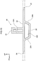
FIG. 3 is a sectional view, along line 3-3 ofFIG. 1 , showing a unit member of the vehicle battery-carrying floor structure pertaining to the embodiment; -
FIG. 4 is a sectional view, along line 4-4 ofFIG. 1 , showing a unit member of the vehicle battery-carrying floor structure pertaining to the embodiment; -
FIG. 5A to FIG. 5D are side sectional views showing joint portions of the unit members of the vehicle battery-carrying floor structure pertaining to the embodiment; -
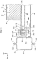
FIG. 6 is a front sectional view showing a state in which the vehicle battery-carrying floor structure pertaining to the embodiment is disposed on the lower side of a floor panel; -
FIG. 7 is a perspective view showing a first example modification of the vehicle battery-carrying floor structure pertaining to the embodiment; -
FIG. 8 is a perspective view showing a second example modification of the vehicle battery-carrying floor structure pertaining to the embodiment; -
FIG. 9 is a perspective view showing a third example modification of the vehicle battery-carrying floor structure pertaining to the embodiment; -
FIG. 10 is a sectional view, corresponding toFIG. 3 , showing an example modification of a partition portion of the unit members of the vehicle battery-carrying floor structure pertaining to the embodiment; -
FIG. 11 is a front sectional view showing a state in which the vehicle battery-carrying floor structure pertaining to the embodiment is disposed on the upper side of the floor panel; -
FIG. 12A is a perspective view showing a bracket for disposing, on the upper side of the floor panel, the vehicle battery-carrying floor structure pertaining to the embodiment; -
FIG. 12B is a perspective view showing other brackets for disposing, on the upper side of the floor panel, the vehicle battery-carrying floor structure pertaining to the embodiment; and -
FIG. 13 is a front sectional view showing another state in which the vehicle battery-carrying floor structure pertaining to the embodiment is disposed on the upper side of the floor panel. - An embodiment pertaining to the disclosure will be described in detail below on the basis of the drawings. It will be noted that for convenience of description, arrow UP appropriately shown in the drawings indicates a vehicle body upward direction, arrow FR indicates a vehicle body forward direction, and arrow RH indicates a vehicle body rightward direction. Consequently, when in the following description the directions of upper/lower, front/rear, and right/left are used without further specification, these will be understood to mean upper/lower in the vehicle body upward and downward direction, front/rear in the vehicle body forward and rearward direction, and right/left in the vehicle body rightward and leftward direction (the vehicle width direction).
- As shown in
FIG. 1 andFIG. 2 , a vehicle battery-carryingfloor structure 10 pertaining to the embodiment is configured by abattery case 12 that holds plural battery packs 50. Thebattery case 12 is configured to includeplural unit members 20 that are coupled to each other in the vehicle body forward and rearward direction. It will be noted that theunit members 20 are formed by extruding a light metal material such as an aluminum alloy. - As shown in
FIG. 1 to FIG. 4 , theunit members 20 each have a rectangular flat plate-shapedflat plate portion 22, which extends in the vehicle width direction and has ajoint portion 24 formed in its end portion facing the vehicle body forward direction and in its end portion facing the vehicle body rearward direction, and a rectangular flat plate-shapedpartition portion 26, which is integrally disposed upright, so as to extend in the vehicle width direction, on an upper surface, and in the vehicle body forward and rearward direction center portion, of theflat plate portion 22. Additionally, theunit members 20 each have areinforcement portion 28 that is integrally formed on a lower surface of theflat plate portion 22 on the opposite side of thepartition portion 26. - It will be noted that a
unit member 20F (seeFIG. 1 andFIG. 2 ) provided on the front end portion is, as shown inFIG. 4 , configured with the part of theflat plate portion 22 on the vehicle body front side of thereinforcement portion 28 being cut off, so that ajoint portion 24 is formed in only the rear end portion of theflat plate portion 22. Likewise, aunit member 20R (seeFIG. 1 andFIG. 2 ) provided on the rear end portion is configured with the part of theflat plate portion 22 on the vehicle body rear side of thereinforcement portion 28 being cut off, so that ajoint portion 24 is formed in only the front end portion of theflat plate portion 22. - As shown in
FIG. 3 andFIG. 4 , thejoint portions 24 are formed stepwise (stepped), and thejoint portions 24 on the vehicle body front side and the vehicle body rear side of eachunit member 20 are formed vertically symmetrical. That is, thejoint portion 24 on the vehicle body front side of eachunit member 20 is formed in such a way that its upper portion side (upper half) sticks out in the vehicle body forward direction, and thejoint portion 24 on the vehicle body rear side of eachunit member 20 is formed in such a way that its lower portion side (lower half) sticks out in the vehicle body rearward direction. - It will be noted that the arrangement of the
unit members 20 may also be bilaterally reversed. In other words, theunit members 20 may also be arranged in such a way that the lower portion side (lower half) of thejoint portion 24 on the vehicle body front side sticks out in the vehicle body forward direction and the upper portion side (upper half) of thejoint portion 24 on the vehicle body rear side stick outs in the vehicle body rearward direction. - Additionally, the
plural unit members 20 including theunit member 20F that configures the front end portion and theunit member 20R that configures the rear end portion are arranged side by side in the vehicle body forward and rearward direction and their mutually opposingjoint portions 24 are engaged with and joined to each other in the upward and downward direction, thereby forming abottom plate member 14 on which the battery packs 50 are placed. It will be noted that examples of the method for joining thejoint portions 24 to each other include friction stir welding (FSW), but the method may also be arc welding or the like. - The
joint portions 24 may be joined to each other just at their upper surface sides (FIG. 5A ) or may be joined to each other just at their lower surface sides (FIG. 5B ). Moreover, thejoint portions 24 may be joined to each other both at their upper surface sides and their lower surface sides (FIG. 5C ). However, from the standpoint of inhibiting or preventing the ingress of muddy water and/or rain water, for example, it is preferred that at least the lower surface sides of thejoint portions 24 be joined to each other. - Furthermore, the
joint portions 24 are not limited to a configuration where they are formed stepwise (stepped). For example, as shown inFIG. 5D , thejoint portions 24 may also be formed in shapes whose mutual end faces abut against each other in the vehicle body forward and rearward direction. It is preferred that thejoint portions 24 in this case be joined to each other both at their upper surface sides and their lower surface sides as shown inFIG. 5D , and from the standpoint described above it is preferred that at least the lower surface sides of thejoint portions 24 in this case be joined to each other. - Furthermore, as shown in
FIG. 1 andFIG. 2 , the vehicle width direction outer end portions of thepartition portions 26 of theunit members 20 have a predetermined length cut out from them. In other words, the length of thepartition members 26 is configured to be shorter than the length of theflat plate portions 22. Additionally, a right and left pair of rectangular flat plate-shapedside plate members 16 that extend in the vehicle body forward and rearward direction are provided by joining such as welding, adhesion, or bolts on the upper surface of thebottom plate member 14 on the vehicle width direction outer sides of thepartition portions 26. - It will be noted that at this time the inner surfaces of the
side plate members 16 may be joined, or may not be joined, to the vehicle width direction outer end faces of thepartition portions 26. Furthermore, it is preferred that front end faces 16F of theside plate members 16 be flush with the front face of apartition portion 26F of theunit member 20F that configures the front end portion. Likewise, it is preferred that rear end faces 16R of theside plate members 16 also be flush with the rear face of apartition portion 26R of theunit member 20R that configures the rear end portion. - An outer frame of the
battery case 12 is formed by theside plate members 16, thepartition portion 26F of theunit member 20F that configures the front end portion, and thepartition portion 26R of theunit member 20R that configures the rear end portion. Furthermore, theside plate members 16 are also formed of the same light metal material-such as an aluminum alloy-as theunit members 20. - Moreover, plural (e.g., four) rectangular flat plate-shaped
intermediate plate members 18 that extend in the vehicle body forward and rearward direction are provided by joining means such as welding, adhesion, or bolts on the upper surfaces, at the vehicle width direction center portions, of theflat plate portions 22. It will be noted that at this time the front end faces and the rear end faces of theintermediate plate members 18 may be joined, or may not be joined, to the rear faces and the front faces of thepartition portions 26. Furthermore, theintermediate plate members 18 are also formed of the same light metal material-such as an aluminum alloy-as theunit members 20. - As shown in
FIG. 2 , plural (e.g., eight) battery packs 50, each formed in a substantially rectangular shape in plan view, are put substantially without any gap into plural (e.g., eight) regions (blocks) E, each substantially rectangular in shape as viewed in plan view, on the upper surface of thebottom plate member 14 and surrounded by thepartition portions 26, theside plate members 16, and theintermediate plate members 18. - The
battery case 12 in which the plural (e.g., eight) battery packs 50 are carried is formed by thebottom plate member 14, theside plate members 16, and theintermediate plate members 18. It will be noted that after the battery packs 50 have been put into thebattery case 12, thebattery case 12 is closed off by covering it with a rectangular flat plate-shaped cover member 48 (seeFIG. 6 ). Thecover member 48 is also formed of the same light metal material-such as an aluminum alloy-as theunit members 20. - Furthermore, the heights of the
partition portions 26, theside plate members 16, and theintermediate plate members 18 shown inFIG. 2 are configured to be identical, but they are not limited to this. For example, as shown inFIG. 6 , theside plate members 16 may also be formed slightly higher than thepartition portions 26 and theintermediate plate members 18. Furthermore, the heights of thepartition portions 26, theside plate members 16, and theintermediate plate members 18 shown inFIG. 2 are configured to be identical to the height of the battery packs 50, but they are not limited to this. For example, the heights of thepartition portions 26, theside plate members 16, and theintermediate plate members 18 may also be formed slightly higher than the height of the battery packs 50. - Furthermore, as shown in
FIG. 3 andFIG. 4 , thereinforcement portions 28 each have, as viewed in cross section from the vehicle width direction (the vehicle body side), afront face 28A that slopes in the vehicle body forward direction heading in the vehicle body upward direction and arear face 28B that slopes in the vehicle body rearward direction heading in the vehicle body upward direction. That is, thereinforcement portions 28 are each formed substantially in the shape of an isosceles trapezoid as viewed in cross section from the vehicle width direction. Additionally, thereinforcement portions 28 are each formed hollow having a substantially isosceles trapezoid-shaped throughhole 28C running in the vehicle width direction through thereinforcement portion 28. - Furthermore,
fastening holes 22A andfastening holes 28D (seeFIG. 6 ) for fastening thebottom plate member 14 to a right and left pair of rockers 30 (seeFIG. 6 ) serving as a vehicle body are formed in theflat plate portions 22 and thereinforcement portions 28 on the vehicle width direction outer sides of theside plate members 16 and on extension lines of thepartition portions 26 extended outward the vehicle width direction as shown inFIG. 1 andFIG. 2 . - Additionally, as shown in
FIG. 6 , open cylinder-shapedcollar members 38 are inserted from the vehicle width direction outer sides into and are provided in the throughholes 28C in thereinforcement portions 28 in such a way that the axial direction of thecollar members 38 coincides with the upward and downward direction, and throughholes 38A in thecollar members 38 are communicated with thefastening holes 22A and the fastening holes 28D. - As shown in
FIG. 6 , the right and left pair ofrockers 30 are each formed in a closed cross-sectional shape as a result of anouter panel 32 and an inner panel 34-each formed substantially in a cross-sectional hat shape-being joined to each other at mutualupper flange portions lower flange portions lower wall 34D of each of the right and leftinner panels 34, plural throughholes 34C are formed a predetermined interval apart from each other in the longitudinal direction of therockers 30, and plural weld nuts 42 are provided, coaxially with the throughholes 34C, on the inner surfaces of thelower walls 34D. - Consequently, the
bottom plate member 14 is fastened to thelower wall 34D sides of the right and left pair ofrockers 30 as a result ofbolts 44 being inserted from below into the fastening holes 28D in thereinforcement portions 28, the throughholes 38A in thecollar members 38, the fastening holes 22A in theflat plate portions 22, and the throughholes 34C in therockers 30 and screwed into the weld nuts 42. Thebattery case 12 into which the plural battery packs 50 have been put is attached to the vehicle body as a result of thebolts 44 being screwed into the weld nuts 42. - Furthermore, as shown in
FIG. 6 , a substantially flat plate-shapedfloor panel 40 bridgesupper walls 34U of the right and leftinner panels 34. The vehicle width direction outer end portions of thefloor panel 40 are joined to theupper walls 34U of theinner panels 34 of therockers 30. Because of this, thebattery case 12 into which the plural battery packs 50 have been put is disposed betweenside walls 34S (vehicle width direction inner sides) of the right and leftrockers 30 and on the lower side of thefloor panel 40. - Next, the action of the vehicle battery-carrying
floor structure 10 pertaining to the embodiment having the above configuration will be described. - As described above, the
unit members 20 are formed by extrusion. Consequently, the strength and rigidity (particularly strength and rigidity with respect to loads input from the vehicle width direction outer sides) of even theunit members 20 having thepartition portions 26 integrally disposed upright on the upper surfaces of theflat plate portions 22 can be ensured. Because of this, the strength and rigidity of thebottom plate member 14 that is configured as a result of theplural unit members 20 being coupled to each other are also ensured. - Furthermore, in the vehicle battery-carrying
floor structure 10 pertaining to the embodiment, changes in the quantity of the battery packs 50 to be carried can be flexibly accommodated. The quantity of theunit members 20 to be coupled to each other is decided, and the size of the bottom plate member 14 (the battery case 12) is decided, in accordance with the quantity of the battery packs 50 to be carried. - For example, in the case of carrying eight battery packs 50 as shown in
FIG. 2 , threeunit members 20 are disposed between theunit member 20F that configures the front end portion and theunit member 20R that configures the rear end portion, and eight regions E are formed by fivepartition portions 26, twoside plate members 16, and fourintermediate plate members 18. - Furthermore, in the case of carrying six battery packs 50, as shown in
FIG. 7 , twounit members 20 are disposed between theunit member 20F that configures the front end portion and theunit member 20R that configures the rear end portion, and six regions E are formed by fourpartition portions 26, twoside plate members 16, and threeintermediate plate members 18. - Moreover, in the case of carrying ten battery packs 50, as shown in
FIG. 8 , fourunit members 20 are disposed between theunit member 20F that configures the front end portion and theunit member 20R that configures the rear end portion, and ten regions E are formed by sixpartition portions 26, twoside plate members 16, and fiveintermediate plate members 18. - In this way, by changing the quantity of the
unit members 20, the size of thebottom plate member 14 can be changed. The size of thebattery case 12 can be changed in accordance with the quantity of the battery packs 50 to be carried. Consequently, flexibility with respect to thebattery pack 50 carrying capacity of thebattery case 12 can be increased. - It will be noted that, as described above, at least the lower surface sides of the
joint portions 24 are joined by friction stir welding (FSW). Consequently, even when thebattery case 12 into which the plural battery packs 50 have been put is disposed between theside walls 34S (the vehicle width direction inner sides) of the right and leftrockers 30 and on the lower side of thefloor panel 40, muddy water and/or rain water, for example, can be inhibited or prevented from getting inside at least from the lower surfaces of thejoint portions 24. - Furthermore, when the
joint portions 24 are joined to each other by friction stir welding (FSW) and not arc welding or the like, thebottom plate member 14 whose dimensional precision is high can be manufactured. That is, with friction stir welding, there is little strain and/or residual stress because thejoint portions 24 can be joined at a lower temperature than the melting point of the unit members 20 (the light metal material such as an aluminum alloy). Consequently, it becomes difficult for warping and twisting to occur in thebottom plate member 14 after the joining, and the dimension precision of thebottom plate member 14 is ensured. - Furthermore, the right and left pair of
side plate members 16 are joined to the upper surfaces of theflat plate portions 22 on the vehicle width direction outer sides of thepartition portions 26, and the pluralintermediate plate members 18 that extend in the vehicle body forward and rearward direction are joined to the upper surfaces, at the vehicle width direction center portions, of theflat plate portions 22. In other words, theside plate members 16 and theintermediate plate members 18 are joined to thebottom plate member 14 that is high in strength and rigidity. Consequently, the occurrence of warping and twisting in thebattery case 12 can be inhibited or prevented, and the product precision of thebattery case 12 can be ensured. - Furthermore, the
battery case 12 is configured by simply joining theside plate members 16 and theintermediate plate members 18 to thebottom plate member 14, so the structure of thebattery case 12 is simple. It will be noted that in a case where the battery packs 50 each have a rectangular shape that is long in the vehicle width direction as shown inFIG. 9 , thebattery case 12 may be configured to not have theintermediate plate members 18. In this way, according to the vehicle battery-carryingfloor structure 10 pertaining to the embodiment, changes in the vehicle width direction length of the battery packs 50 can be flexibly accommodated, and the vehicle battery-carryingfloor structure 10 can hold the battery packs 50. - Furthermore, the
reinforcement portions 28 are formed on the lower surfaces of theflat plate portions 22 on the opposite sides of thepartition portions 26. Consequently, the strength and rigidity of the parts where thepartition portions 26 are formed can be enhanced by thereinforcement portions 28. Furthermore, thereinforcement portions 28 each have, as viewed in cross section from the vehicle width direction, thefront face 28A that slopes in the vehicle body forward direction heading in the vehicle body upward direction and therear face 28B that slopes in the vehicle body rearward direction heading in the vehicle body upward direction. - Consequently, even if rocks and the like on road surfaces hit the front faces 28A or the rear faces 28B of the
reinforcement portions 28 while the vehicle is traveling (including not only forward travel but also backward travel), the rocks and the like do not catch on thereinforcement portions 28. Even if rocks and the like hit the front faces 28A or the rear faces 28B of thereinforcement portions 28, thereinforcement portions 28 can simply go over the rocks and the like. Thus, damage to thereinforcement portions 28 can be inhibited or prevented. - Furthermore, the
reinforcement portions 28 are formed hollow. Consequently, the bottom plate member 14 (the battery case 12) can be made lighter in weight compared to a case where thereinforcement portions 28 are formed solid. It will be noted that not only thereinforcement portions 28 but also thepartition portions 26 may be formed hollow as shown inFIG. 10 for example. - That is, in a case where the plate thickness of the
partition portions 26 is formed thicker than the plate thickness of thepartition portions 26 shown inFIG. 3 andFIG. 4 to further enhance the strength of theunit members 20, rectangular throughholes 26A running in the vehicle width direction through thepartition portions 26 may also be formed in thepartition portions 26. According to this, even when the plate thickness of thepartition portions 26 is thick, an increase in the weight of theunit members 20 can be inhibited or prevented (thebottom plate member 14 can be made lighter in weight) compared to a case where thepartition portions 26 are formed solid. - Furthermore, as shown in
FIG. 6 , thebattery case 12 is attached to the vehicle body as a result of the vehicle width direction outer end portions of thebottom plate member 14 being fastened by thebolts 44 and the weld nuts 42 to thelower wall 34D sides of therockers 30. That is, thefastening holes 22A and the fastening holes 28D in thebottom plate member 14 are formed in theflat plate portions 22 and thereinforcement portions 28 on the vehicle width direction outer sides of theside plate members 16 and on extension lines of thepartition portions 26 extended outward the vehicle width direction. - Here, the
flat plate portions 22 on the extension lines of thepartition portions 26 extended outward the vehicle width direction are increased in strength and rigidity because of thereinforcement portions 28. Consequently, thebattery case 12 can be attached with good precision to the vehicle body (the rockers 30). It will be noted that thebattery case 12 that configures the vehicle battery-carryingfloor structure 10 pertaining to the embodiment is not limited to a configuration where it is disposed on the lower side of thefloor panel 40. - In a case where the
floor panel 40 bridges the lower portion sides of theside walls 34S of the right and leftinner panels 34 as shown inFIG. 11 for example, thebattery case 12 may be disposed on the upper side of thefloor panel 40 usingbrackets 36 that are each formed stepwise as viewed from the vehicle body forward and rearward direction and extend in the vehicle body forward and rearward direction (the longitudinal direction of the rockers 30). - Specifically, as shown in
FIG. 11 andFIG. 12A , as viewed from the vehicle body forward and rearward direction, thebrackets 36 each have amain body portion 36A that is disposed horizontally, oneend portion 36B that is bent in the vehicle body upward direction from the vehicle width direction outer end portion of themain body portion 36A, and anotherend portion 36C that is bent substantially in a cross-sectional L-shape in the vehicle body downward direction from the vehicle width direction inner end portion of themain body portion 36A. - Furthermore, in the
main body portion 36A of eachbracket 36, plural throughholes 36D are formed a predetermined interval apart from each other so as to correspond to theplural fastening holes 28D andfastening holes 22A, and plural weld nuts 42 are provided, coaxially with the throughholes 36D, on the lower surface of eachmain body portion 36. Additionally, the oneend portions 36B of thebrackets 36 are joined to theside walls 34S of the right and leftinner panels 34, and theother end portions 36C of thebrackets 36 are joined to the upper surface of thefloor panel 40. - In this configuration, the
reinforcement portions 28 are disposed on the upper surfaces of themain body portions 36A of thebrackets 36, and thebolts 44 are inserted from above into the fastening holes 22A in theflat plate portions 22, the throughholes 38A in thecollar members 38, the fastening holes 28D in thereinforcement portions 28, and the throughholes 36D in thebrackets 36 and are screwed into the weld nuts 42, whereby thebottom plate member 14 is attached to thebrackets 36. - In other words, the
battery case 12 that configures the vehicle battery-carryingfloor structure 10 pertaining to the embodiment is disposed between theside walls 34S (the vehicle width direction inner sides) of the right and leftrockers 30 and on the upper side of thefloor panel 40. It will be noted that each of thebrackets 36 may also be segmented into plural brackets in the vehicle body forward and rearward direction as shown inFIG. 12B for example. - Specifically, as shown in
FIG. 12B , each of thesegmented brackets 36 is formed as an enclosure whose vehicle width direction outer side and vehicle body lower side are open, with the upper wall thereof being themain body portion 36A having the throughhole 36D. Additionally, the weld nuts 42 (seeFIG. 11 ) are provided, coaxially with the throughholes 36D, on the lower surfaces of themain body portions 36A of thebrackets 36. - Furthermore,
flange portions 36E that stick out in the vehicle body upward direction, the vehicle body forward direction, and the vehicle body rearward direction are integrally formed on the vehicle width direction outer peripheral edge portions of thebrackets 36, andflange portions 36F that stick out inward in the vehicle width direction, the vehicle body forward direction, and the vehicle body rearward direction are integrally formed on the vehicle body lower peripheral edge portions of thebrackets 36. - Additionally, the
brackets 36 are disposed a predetermined interval apart from each other in such a way that the throughholes 36D correspond to theplural fastening holes 28D andfastening holes 22A, theflange portions 36E are joined to theside walls 34S of the right and leftinner panels 34, and theflange portions 36F are joined to the upper surface of thefloor panel 40. - In this configuration, the
reinforcement portions 28 are disposed on the upper surfaces of themain body portions 36A of thebrackets 36, and thebolts 44 are inserted from above into the fastening holes 22A in theflat plate portions 22, the throughholes 38A in thecollar members 38, the fastening holes 28D in thereinforcement portions 28, and the throughholes 36D in thebrackets 36 and are screwed into the weld nuts 42, whereby thebottom plate member 14 is attached to thebrackets 36. - Furthermore, as shown in
FIG. 13 for example, in a case where thefloor panel 40 bridges the upper portion sides of theside walls 34S of the right and leftinner panels 34, plural throughholes 34E may be formed a predetermined interval apart from each other in theupper walls 34U of theinner panels 34 so as to correspond to theplural fastening holes 28D andfastening holes 22A, and plural weld nuts 42 may be provided, coaxially with the throughholes 34E, on the lower surfaces of theupper walls 34E. - In this configuration, the
bolts 44 are inserted from above into the fastening holes 22A in theflat plate portions 22, the throughholes 38A in thecollar members 38, the fastening holes 28D in thereinforcement portions 28, and the throughholes 34E in theinner panels 34 and are screwed into the weld nuts 42, whereby thebottom plate member 14 is attached to theupper wall 34U sides of therockers 30. In other words, thebattery case 12 that configures the vehicle battery-carryingfloor structure 10 pertaining to the embodiment is disposed on the upper side of the right and leftrockers 30 and thefloor panel 40. - The vehicle battery-carrying
floor structure 10 pertaining to the embodiment has been described above on the basis of the drawings, but the vehicle battery-carryingfloor structure 10 pertaining to the embodiment is not limited to what is shown in the drawings and its design can be appropriately changed in a range that does not depart from the spirit of the disclosure. For example, thejoint portion 24 on the vehicle body front side and the joint portion on the vehicle body rear side of eachunit member 20 may also have the same shape. - In other words, the
joint portions 24 of oneunit member 20 may be formed in such a way that their upper portion sides (upper halves) stick out, thejoint portions 24 of anotherunit member 20 may be formed in such a way that their lower portion sides (lower halves) stick out, and the oneunit member 20 and theother unit member 20 may be alternately joined to each other. - However, in this configuration, both the one
unit member 20 and theother unit member 20 must be extruded, and two molds become necessary. In contrast, when thejoint portion 24 on the vehicle body front side and thejoint portion 24 on the vehicle body rear side of eachunit member 20 are formed vertically symmetrical as they are in theunit members 20 pertaining to the above embodiment, one mold suffices, so manufacturing costs can be reduced compared to a case where two molds become necessary. - Furthermore, in a case where the plate thickness of the
side plate members 16 and/or theintermediate plate members 18 is formed thick as in thepartition portions 26 shown inFIG. 10 to further enhance the strength of thebattery case 12, theside plate members 16 and/or theintermediate plate members 18 may also be formed hollow. According to this, even when the plate thickness of theside plate members 16 and/or theintermediate plate members 18 is thick, an increase in the weight of thebattery case 12 can be inhibited or prevented (thebattery case 12 can be made lighter in weight) compared to a case where theside plate members 16 and/or theintermediate plate members 18 are formed solid.
Claims (10)
- A vehicle battery-carrying floor structure comprising:a bottom plate member (14) that has a plurality of unit members (20) that are arranged in a vehicle body forward and rearward direction and that are joined by joining opposing joint portions (24), each unit member (20) having a flat plate portion (22) that extends in a vehicle width direction and that has the joint portions formed at an end portion facing the vehicle body forward direction and at an end portion facing the vehicle body rear direction and a partition portion (26) that is disposed upright so as to extend in the vehicle width direction on an upper surface of the plate portion (22); andside plate members (16) that are provided on an upper surface of the bottom plate member (14) on outer sides in the vehicle width direction of the partition portions (26) and form, with the partition portions (26), regions that hold battery packs.
- The vehicle battery-carrying floor structure according to claim 1, wherein reinforcement portions (28) are formed on lower surfaces of the flat plate portions (22) on opposite sides from the partition portions (26).
- The vehicle battery-carrying floor structure according to claim 2, wherein the reinforcement portions (28) each have, as viewed in cross section from the vehicle width direction, a front face that slopes in the vehicle body forward direction heading in a vehicle body upward direction and a rear face that slopes in the vehicle body rearward direction heading in the vehicle body upward direction.
- The vehicle battery-carrying floor structure according to claim 2 or claim 3, wherein the reinforcement portions are hollow.
- The vehicle battery-carrying floor structure according to any one of claim 2 to claim 4, wherein fastening holes (22A, 28D) that fasten the bottom plate member to a vehicle body are formed in the flat plate portions (22) and the reinforcement portions (28) on outer sides in the vehicle width direction of the side plate members (16) and on extension lines of the partition portions extended outward in the vehicle width direction.
- The vehicle battery-carrying floor structure according to any one of claim 1 to claim 5, wherein the partition portions (26) are hollow.
- The vehicle battery-carrying floor structure according to any one of claim 1 to claim 6, wherein intermediate plate members (18) that extend in the vehicle body forward and rearward direction are provided on the upper surfaces, at center portions in the vehicle width direction, of the flat plate portions (22).
- The vehicle battery-carrying floor structure according to any one of claim 1 to claim 7, wherein at least lower surface sides of the joint portions (24) are friction stir welded.
- The vehicle battery-carrying floor structure according to any one of claim 1 to claim 8, wherein the joint portions (24) are formed stepwise.
- The vehicle battery-carrying floor structure according to any one of claim 7 to claim 9, wherein each of at least one of the side plate members (16) or the intermediate plate members (18) is hollow.
Applications Claiming Priority (1)
| Application Number | Priority Date | Filing Date | Title |
|---|---|---|---|
| JP2018139351A JP7040338B2 (en) | 2018-07-25 | 2018-07-25 | Floor structure with vehicle batteries |
Publications (2)
| Publication Number | Publication Date |
|---|---|
| EP3608137A1 true EP3608137A1 (en) | 2020-02-12 |
| EP3608137B1 EP3608137B1 (en) | 2021-09-22 |
Family
ID=67001609
Family Applications (1)
| Application Number | Title | Priority Date | Filing Date |
|---|---|---|---|
| EP19181632.1A Active EP3608137B1 (en) | 2018-07-25 | 2019-06-21 | Vehicle battery-carrying floor structure |
Country Status (4)
| Country | Link |
|---|---|
| US (1) | US10894470B2 (en) |
| EP (1) | EP3608137B1 (en) |
| JP (1) | JP7040338B2 (en) |
| CN (1) | CN110789620B (en) |
Cited By (1)
| Publication number | Priority date | Publication date | Assignee | Title |
|---|---|---|---|---|
| FR3118905A1 (en) | 2021-01-18 | 2022-07-22 | Psa Automobiles Sa | ELECTRIC VEHICLE PLATFORM MODULE |
Families Citing this family (6)
| Publication number | Priority date | Publication date | Assignee | Title |
|---|---|---|---|---|
| JP7047479B2 (en) * | 2018-03-09 | 2022-04-05 | トヨタ自動車株式会社 | Vehicle undercarriage |
| JP7172887B2 (en) * | 2019-07-02 | 2022-11-16 | トヨタ自動車株式会社 | Underbody structure |
| CN113352866B (en) * | 2020-03-04 | 2024-02-27 | 比亚迪股份有限公司 | Battery tray, battery package and electric automobile |
| DE102020212709A1 (en) | 2020-10-08 | 2022-04-14 | Elringklinger Ag | Battery device and method of manufacturing a battery device |
| KR102934935B1 (en) * | 2020-12-16 | 2026-03-05 | 현대자동차 주식회사 | Frame joint structure and method |
| DE102021122415A1 (en) * | 2021-08-31 | 2023-03-02 | Bayerische Motoren Werke Aktiengesellschaft | Energy storage floor system for a motor vehicle |
Citations (5)
| Publication number | Priority date | Publication date | Assignee | Title |
|---|---|---|---|---|
| DE102012100977B3 (en) * | 2012-02-07 | 2013-07-18 | Benteler Automobiltechnik Gmbh | Energy storage container i.e. box-shaped aluminum intake carrier, for carrying e.g. lithium-ion cells of energy store module in motor car, has base plate whose profiled element is connected to adjacent element simultaneously as side walls |
| JP5372128B2 (en) | 2010-12-22 | 2013-12-18 | テスラ・モーターズ・インコーポレーテッド | Side impact energy absorption and dispersion system using battery pack |
| GB2541203A (en) * | 2015-08-11 | 2017-02-15 | Jaguar Land Rover Ltd | Apparatus for supporting a battery |
| DE102016213832A1 (en) * | 2016-07-27 | 2018-02-01 | Volkswagen Aktiengesellschaft | Lower shell for a battery housing with integrated cooling and traction battery for a motor vehicle |
| EP3345779A1 (en) * | 2017-01-05 | 2018-07-11 | Samsung SDI Co., Ltd. | Vehicle body part and vehicle with integrated battery system |
Family Cites Families (11)
| Publication number | Priority date | Publication date | Assignee | Title |
|---|---|---|---|---|
| JP3406074B2 (en) * | 1994-08-23 | 2003-05-12 | 国立環境研究所長 | Chassis frame for electric vehicles |
| JPH09226632A (en) * | 1996-02-22 | 1997-09-02 | Toyota Motor Corp | Body structure of electric vehicle |
| CN2530860Y (en) * | 2001-10-24 | 2003-01-15 | 于耀庆 | Structure of composite material for electric vehicle body |
| JP5408441B2 (en) | 2010-01-18 | 2014-02-05 | 三菱自動車工業株式会社 | Battery case for vehicle |
| US9281505B2 (en) | 2012-10-16 | 2016-03-08 | Toyota Jidosha Kabushiki Kaisha | Battery mounting structure for vehicle |
| US20180105062A1 (en) * | 2016-10-14 | 2018-04-19 | Inevit, Inc. | Battery module compartment chamber and battery module mounting area of an energy storage system and method thereof |
| JP6555236B2 (en) * | 2016-11-30 | 2019-08-07 | トヨタ自動車株式会社 | Lower body structure |
| US10483510B2 (en) * | 2017-05-16 | 2019-11-19 | Shape Corp. | Polarized battery tray for a vehicle |
| WO2019071013A1 (en) * | 2017-10-04 | 2019-04-11 | Shape Corp. | Battery tray floor assembly for electric vehicles |
| JP6992585B2 (en) * | 2018-02-22 | 2022-01-13 | トヨタ自動車株式会社 | Vehicle undercarriage |
| DE102018131376B4 (en) * | 2018-12-07 | 2024-05-23 | Benteler Automobiltechnik Gmbh | Battery carrier with surrounding frame and defined adhesive gap |
-
2018
- 2018-07-25 JP JP2018139351A patent/JP7040338B2/en active Active
-
2019
- 2019-05-31 CN CN201910468833.3A patent/CN110789620B/en active Active
- 2019-06-21 EP EP19181632.1A patent/EP3608137B1/en active Active
- 2019-06-21 US US16/448,600 patent/US10894470B2/en active Active
Patent Citations (5)
| Publication number | Priority date | Publication date | Assignee | Title |
|---|---|---|---|---|
| JP5372128B2 (en) | 2010-12-22 | 2013-12-18 | テスラ・モーターズ・インコーポレーテッド | Side impact energy absorption and dispersion system using battery pack |
| DE102012100977B3 (en) * | 2012-02-07 | 2013-07-18 | Benteler Automobiltechnik Gmbh | Energy storage container i.e. box-shaped aluminum intake carrier, for carrying e.g. lithium-ion cells of energy store module in motor car, has base plate whose profiled element is connected to adjacent element simultaneously as side walls |
| GB2541203A (en) * | 2015-08-11 | 2017-02-15 | Jaguar Land Rover Ltd | Apparatus for supporting a battery |
| DE102016213832A1 (en) * | 2016-07-27 | 2018-02-01 | Volkswagen Aktiengesellschaft | Lower shell for a battery housing with integrated cooling and traction battery for a motor vehicle |
| EP3345779A1 (en) * | 2017-01-05 | 2018-07-11 | Samsung SDI Co., Ltd. | Vehicle body part and vehicle with integrated battery system |
Cited By (1)
| Publication number | Priority date | Publication date | Assignee | Title |
|---|---|---|---|---|
| FR3118905A1 (en) | 2021-01-18 | 2022-07-22 | Psa Automobiles Sa | ELECTRIC VEHICLE PLATFORM MODULE |
Also Published As
| Publication number | Publication date |
|---|---|
| JP2020015407A (en) | 2020-01-30 |
| US20200031214A1 (en) | 2020-01-30 |
| CN110789620A (en) | 2020-02-14 |
| EP3608137B1 (en) | 2021-09-22 |
| JP7040338B2 (en) | 2022-03-23 |
| US10894470B2 (en) | 2021-01-19 |
| CN110789620B (en) | 2021-11-16 |
Similar Documents
| Publication | Publication Date | Title |
|---|---|---|
| EP3608137B1 (en) | Vehicle battery-carrying floor structure | |
| CN111341955B (en) | Battery case structure for vehicle | |
| US11787278B2 (en) | Battery tray floor assembly for electric vehicles | |
| US10603998B2 (en) | Battery mounting structure | |
| EP3613656B1 (en) | Vehicle front portion structure | |
| US20160068193A1 (en) | Vehicle front section structure | |
| US20190233021A1 (en) | Two-piece deck post | |
| CN106864600B (en) | Front wall reinforcement and vehicle | |
| JP6849103B2 (en) | Storage bin for assembling to the vehicle body structure | |
| JP3750856B2 (en) | Waveguide | |
| US9758196B2 (en) | Vehicle framework reinforcement structure | |
| US10745056B2 (en) | Front pillar for a vehicle body | |
| US7805840B2 (en) | Method of manufacture of an automobile structure and an automobile structure made by the method | |
| JP5319194B2 (en) | Industrial vehicle counterweight structure | |
| CN214366265U (en) | oil pan assembly | |
| JP2022097815A (en) | Structure of vehicular battery pack | |
| US10940898B2 (en) | Vehicle composite member, vehicle, vehicle manufacturing method, and mixed flow production method | |
| EP3501954A1 (en) | Single-piece floor structure made of a composite material | |
| JP6507873B2 (en) | Car body front structure of car | |
| CN121007171A (en) | Vehicle fastening structure | |
| CN121671748A (en) | Vehicle rear structure | |
| WO2025192066A1 (en) | Battery cell tray | |
| JP2014091429A (en) | Vehicle door structure | |
| JP2004345560A (en) | Automotive body frame material joining structure |
Legal Events
| Date | Code | Title | Description |
|---|---|---|---|
| PUAI | Public reference made under article 153(3) epc to a published international application that has entered the european phase |
Free format text: ORIGINAL CODE: 0009012 |
|
| STAA | Information on the status of an ep patent application or granted ep patent |
Free format text: STATUS: REQUEST FOR EXAMINATION WAS MADE |
|
| 17P | Request for examination filed |
Effective date: 20190621 |
|
| AK | Designated contracting states |
Kind code of ref document: A1 Designated state(s): AL AT BE BG CH CY CZ DE DK EE ES FI FR GB GR HR HU IE IS IT LI LT LU LV MC MK MT NL NO PL PT RO RS SE SI SK SM TR |
|
| AX | Request for extension of the european patent |
Extension state: BA ME |
|
| GRAP | Despatch of communication of intention to grant a patent |
Free format text: ORIGINAL CODE: EPIDOSNIGR1 |
|
| STAA | Information on the status of an ep patent application or granted ep patent |
Free format text: STATUS: GRANT OF PATENT IS INTENDED |
|
| INTG | Intention to grant announced |
Effective date: 20210507 |
|
| GRAS | Grant fee paid |
Free format text: ORIGINAL CODE: EPIDOSNIGR3 |
|
| GRAA | (expected) grant |
Free format text: ORIGINAL CODE: 0009210 |
|
| STAA | Information on the status of an ep patent application or granted ep patent |
Free format text: STATUS: THE PATENT HAS BEEN GRANTED |
|
| AK | Designated contracting states |
Kind code of ref document: B1 Designated state(s): AL AT BE BG CH CY CZ DE DK EE ES FI FR GB GR HR HU IE IS IT LI LT LU LV MC MK MT NL NO PL PT RO RS SE SI SK SM TR |
|
| REG | Reference to a national code |
Ref country code: GB Ref legal event code: FG4D |
|
| REG | Reference to a national code |
Ref country code: DE Ref legal event code: R096 Ref document number: 602019007800 Country of ref document: DE |
|
| REG | Reference to a national code |
Ref country code: IE Ref legal event code: FG4D |
|
| REG | Reference to a national code |
Ref country code: CH Ref legal event code: EP Ref country code: AT Ref legal event code: REF Ref document number: 1432052 Country of ref document: AT Kind code of ref document: T Effective date: 20211015 |
|
| REG | Reference to a national code |
Ref country code: LT Ref legal event code: MG9D |
|
| REG | Reference to a national code |
Ref country code: NL Ref legal event code: MP Effective date: 20210922 |
|
| PG25 | Lapsed in a contracting state [announced via postgrant information from national office to epo] |
Ref country code: FI Free format text: LAPSE BECAUSE OF FAILURE TO SUBMIT A TRANSLATION OF THE DESCRIPTION OR TO PAY THE FEE WITHIN THE PRESCRIBED TIME-LIMIT Effective date: 20210922 Ref country code: SE Free format text: LAPSE BECAUSE OF FAILURE TO SUBMIT A TRANSLATION OF THE DESCRIPTION OR TO PAY THE FEE WITHIN THE PRESCRIBED TIME-LIMIT Effective date: 20210922 Ref country code: RS Free format text: LAPSE BECAUSE OF FAILURE TO SUBMIT A TRANSLATION OF THE DESCRIPTION OR TO PAY THE FEE WITHIN THE PRESCRIBED TIME-LIMIT Effective date: 20210922 Ref country code: LT Free format text: LAPSE BECAUSE OF FAILURE TO SUBMIT A TRANSLATION OF THE DESCRIPTION OR TO PAY THE FEE WITHIN THE PRESCRIBED TIME-LIMIT Effective date: 20210922 Ref country code: BG Free format text: LAPSE BECAUSE OF FAILURE TO SUBMIT A TRANSLATION OF THE DESCRIPTION OR TO PAY THE FEE WITHIN THE PRESCRIBED TIME-LIMIT Effective date: 20211222 Ref country code: HR Free format text: LAPSE BECAUSE OF FAILURE TO SUBMIT A TRANSLATION OF THE DESCRIPTION OR TO PAY THE FEE WITHIN THE PRESCRIBED TIME-LIMIT Effective date: 20210922 Ref country code: NO Free format text: LAPSE BECAUSE OF FAILURE TO SUBMIT A TRANSLATION OF THE DESCRIPTION OR TO PAY THE FEE WITHIN THE PRESCRIBED TIME-LIMIT Effective date: 20211222 |
|
| REG | Reference to a national code |
Ref country code: AT Ref legal event code: MK05 Ref document number: 1432052 Country of ref document: AT Kind code of ref document: T Effective date: 20210922 |
|
| PG25 | Lapsed in a contracting state [announced via postgrant information from national office to epo] |
Ref country code: LV Free format text: LAPSE BECAUSE OF FAILURE TO SUBMIT A TRANSLATION OF THE DESCRIPTION OR TO PAY THE FEE WITHIN THE PRESCRIBED TIME-LIMIT Effective date: 20210922 Ref country code: GR Free format text: LAPSE BECAUSE OF FAILURE TO SUBMIT A TRANSLATION OF THE DESCRIPTION OR TO PAY THE FEE WITHIN THE PRESCRIBED TIME-LIMIT Effective date: 20211223 |
|
| PG25 | Lapsed in a contracting state [announced via postgrant information from national office to epo] |
Ref country code: AT Free format text: LAPSE BECAUSE OF FAILURE TO SUBMIT A TRANSLATION OF THE DESCRIPTION OR TO PAY THE FEE WITHIN THE PRESCRIBED TIME-LIMIT Effective date: 20210922 |
|
| PG25 | Lapsed in a contracting state [announced via postgrant information from national office to epo] |
Ref country code: IS Free format text: LAPSE BECAUSE OF FAILURE TO SUBMIT A TRANSLATION OF THE DESCRIPTION OR TO PAY THE FEE WITHIN THE PRESCRIBED TIME-LIMIT Effective date: 20220122 Ref country code: SK Free format text: LAPSE BECAUSE OF FAILURE TO SUBMIT A TRANSLATION OF THE DESCRIPTION OR TO PAY THE FEE WITHIN THE PRESCRIBED TIME-LIMIT Effective date: 20210922 Ref country code: RO Free format text: LAPSE BECAUSE OF FAILURE TO SUBMIT A TRANSLATION OF THE DESCRIPTION OR TO PAY THE FEE WITHIN THE PRESCRIBED TIME-LIMIT Effective date: 20210922 Ref country code: PT Free format text: LAPSE BECAUSE OF FAILURE TO SUBMIT A TRANSLATION OF THE DESCRIPTION OR TO PAY THE FEE WITHIN THE PRESCRIBED TIME-LIMIT Effective date: 20220124 Ref country code: PL Free format text: LAPSE BECAUSE OF FAILURE TO SUBMIT A TRANSLATION OF THE DESCRIPTION OR TO PAY THE FEE WITHIN THE PRESCRIBED TIME-LIMIT Effective date: 20210922 Ref country code: NL Free format text: LAPSE BECAUSE OF FAILURE TO SUBMIT A TRANSLATION OF THE DESCRIPTION OR TO PAY THE FEE WITHIN THE PRESCRIBED TIME-LIMIT Effective date: 20210922 Ref country code: ES Free format text: LAPSE BECAUSE OF FAILURE TO SUBMIT A TRANSLATION OF THE DESCRIPTION OR TO PAY THE FEE WITHIN THE PRESCRIBED TIME-LIMIT Effective date: 20210922 Ref country code: EE Free format text: LAPSE BECAUSE OF FAILURE TO SUBMIT A TRANSLATION OF THE DESCRIPTION OR TO PAY THE FEE WITHIN THE PRESCRIBED TIME-LIMIT Effective date: 20210922 Ref country code: CZ Free format text: LAPSE BECAUSE OF FAILURE TO SUBMIT A TRANSLATION OF THE DESCRIPTION OR TO PAY THE FEE WITHIN THE PRESCRIBED TIME-LIMIT Effective date: 20210922 Ref country code: AL Free format text: LAPSE BECAUSE OF FAILURE TO SUBMIT A TRANSLATION OF THE DESCRIPTION OR TO PAY THE FEE WITHIN THE PRESCRIBED TIME-LIMIT Effective date: 20210922 |
|
| REG | Reference to a national code |
Ref country code: DE Ref legal event code: R097 Ref document number: 602019007800 Country of ref document: DE |
|
| PG25 | Lapsed in a contracting state [announced via postgrant information from national office to epo] |
Ref country code: DK Free format text: LAPSE BECAUSE OF FAILURE TO SUBMIT A TRANSLATION OF THE DESCRIPTION OR TO PAY THE FEE WITHIN THE PRESCRIBED TIME-LIMIT Effective date: 20210922 |
|
| PLBE | No opposition filed within time limit |
Free format text: ORIGINAL CODE: 0009261 |
|
| STAA | Information on the status of an ep patent application or granted ep patent |
Free format text: STATUS: NO OPPOSITION FILED WITHIN TIME LIMIT |
|
| 26N | No opposition filed |
Effective date: 20220623 |
|
| PG25 | Lapsed in a contracting state [announced via postgrant information from national office to epo] |
Ref country code: SI Free format text: LAPSE BECAUSE OF FAILURE TO SUBMIT A TRANSLATION OF THE DESCRIPTION OR TO PAY THE FEE WITHIN THE PRESCRIBED TIME-LIMIT Effective date: 20210922 |
|
| PG25 | Lapsed in a contracting state [announced via postgrant information from national office to epo] |
Ref country code: MC Free format text: LAPSE BECAUSE OF FAILURE TO SUBMIT A TRANSLATION OF THE DESCRIPTION OR TO PAY THE FEE WITHIN THE PRESCRIBED TIME-LIMIT Effective date: 20210922 Ref country code: IT Free format text: LAPSE BECAUSE OF FAILURE TO SUBMIT A TRANSLATION OF THE DESCRIPTION OR TO PAY THE FEE WITHIN THE PRESCRIBED TIME-LIMIT Effective date: 20210922 |
|
| REG | Reference to a national code |
Ref country code: CH Ref legal event code: PL |
|
| REG | Reference to a national code |
Ref country code: BE Ref legal event code: MM Effective date: 20220630 |
|
| PG25 | Lapsed in a contracting state [announced via postgrant information from national office to epo] |
Ref country code: LU Free format text: LAPSE BECAUSE OF NON-PAYMENT OF DUE FEES Effective date: 20220621 Ref country code: LI Free format text: LAPSE BECAUSE OF NON-PAYMENT OF DUE FEES Effective date: 20220630 Ref country code: IE Free format text: LAPSE BECAUSE OF NON-PAYMENT OF DUE FEES Effective date: 20220621 Ref country code: CH Free format text: LAPSE BECAUSE OF NON-PAYMENT OF DUE FEES Effective date: 20220630 |
|
| PG25 | Lapsed in a contracting state [announced via postgrant information from national office to epo] |
Ref country code: BE Free format text: LAPSE BECAUSE OF NON-PAYMENT OF DUE FEES Effective date: 20220630 |
|
| P01 | Opt-out of the competence of the unified patent court (upc) registered |
Effective date: 20230427 |
|
| REG | Reference to a national code |
Ref country code: DE Ref legal event code: R084 Ref document number: 602019007800 Country of ref document: DE |
|
| REG | Reference to a national code |
Ref country code: GB Ref legal event code: 746 Effective date: 20230731 |
|
| PG25 | Lapsed in a contracting state [announced via postgrant information from national office to epo] |
Ref country code: SM Free format text: LAPSE BECAUSE OF FAILURE TO SUBMIT A TRANSLATION OF THE DESCRIPTION OR TO PAY THE FEE WITHIN THE PRESCRIBED TIME-LIMIT Effective date: 20210922 Ref country code: MK Free format text: LAPSE BECAUSE OF FAILURE TO SUBMIT A TRANSLATION OF THE DESCRIPTION OR TO PAY THE FEE WITHIN THE PRESCRIBED TIME-LIMIT Effective date: 20210922 Ref country code: CY Free format text: LAPSE BECAUSE OF FAILURE TO SUBMIT A TRANSLATION OF THE DESCRIPTION OR TO PAY THE FEE WITHIN THE PRESCRIBED TIME-LIMIT Effective date: 20210922 |
|
| PG25 | Lapsed in a contracting state [announced via postgrant information from national office to epo] |
Ref country code: HU Free format text: LAPSE BECAUSE OF FAILURE TO SUBMIT A TRANSLATION OF THE DESCRIPTION OR TO PAY THE FEE WITHIN THE PRESCRIBED TIME-LIMIT; INVALID AB INITIO Effective date: 20190621 |
|
| PG25 | Lapsed in a contracting state [announced via postgrant information from national office to epo] |
Ref country code: TR Free format text: LAPSE BECAUSE OF FAILURE TO SUBMIT A TRANSLATION OF THE DESCRIPTION OR TO PAY THE FEE WITHIN THE PRESCRIBED TIME-LIMIT Effective date: 20210922 |
|
| PG25 | Lapsed in a contracting state [announced via postgrant information from national office to epo] |
Ref country code: MT Free format text: LAPSE BECAUSE OF FAILURE TO SUBMIT A TRANSLATION OF THE DESCRIPTION OR TO PAY THE FEE WITHIN THE PRESCRIBED TIME-LIMIT Effective date: 20210922 |
|
| PGFP | Annual fee paid to national office [announced via postgrant information from national office to epo] |
Ref country code: DE Payment date: 20250402 Year of fee payment: 7 |
|
| PGFP | Annual fee paid to national office [announced via postgrant information from national office to epo] |
Ref country code: GB Payment date: 20250401 Year of fee payment: 7 |
|
| PGFP | Annual fee paid to national office [announced via postgrant information from national office to epo] |
Ref country code: FR Payment date: 20250409 Year of fee payment: 7 |