EP3608062A1 - Tool for a nut on a screw of a shock absorber - Google Patents
Tool for a nut on a screw of a shock absorber Download PDFInfo
- Publication number
- EP3608062A1 EP3608062A1 EP18188598.9A EP18188598A EP3608062A1 EP 3608062 A1 EP3608062 A1 EP 3608062A1 EP 18188598 A EP18188598 A EP 18188598A EP 3608062 A1 EP3608062 A1 EP 3608062A1
- Authority
- EP
- European Patent Office
- Prior art keywords
- hole
- tool
- polygonal
- connecting rod
- sleeve
- Prior art date
- Legal status (The legal status is an assumption and is not a legal conclusion. Google has not performed a legal analysis and makes no representation as to the accuracy of the status listed.)
- Withdrawn
Links
Images


Classifications
-
- B—PERFORMING OPERATIONS; TRANSPORTING
- B25—HAND TOOLS; PORTABLE POWER-DRIVEN TOOLS; MANIPULATORS
- B25B—TOOLS OR BENCH DEVICES NOT OTHERWISE PROVIDED FOR, FOR FASTENING, CONNECTING, DISENGAGING, OR HOLDING
- B25B13/00—Spanners; Wrenches
- B25B13/02—Spanners; Wrenches with rigid jaws
- B25B13/06—Spanners; Wrenches with rigid jaws of socket type
-
- B—PERFORMING OPERATIONS; TRANSPORTING
- B25—HAND TOOLS; PORTABLE POWER-DRIVEN TOOLS; MANIPULATORS
- B25B—TOOLS OR BENCH DEVICES NOT OTHERWISE PROVIDED FOR, FOR FASTENING, CONNECTING, DISENGAGING, OR HOLDING
- B25B13/00—Spanners; Wrenches
- B25B13/48—Spanners; Wrenches for special purposes
- B25B13/488—Spanners; Wrenches for special purposes for connections where two parts must be turned in opposite directions by one tool
-
- B—PERFORMING OPERATIONS; TRANSPORTING
- B25—HAND TOOLS; PORTABLE POWER-DRIVEN TOOLS; MANIPULATORS
- B25B—TOOLS OR BENCH DEVICES NOT OTHERWISE PROVIDED FOR, FOR FASTENING, CONNECTING, DISENGAGING, OR HOLDING
- B25B23/00—Details of, or accessories for, spanners, wrenches, screwdrivers
- B25B23/0007—Connections or joints between tool parts
- B25B23/0035—Connection means between socket or screwdriver bit and tool
-
- B—PERFORMING OPERATIONS; TRANSPORTING
- B25—HAND TOOLS; PORTABLE POWER-DRIVEN TOOLS; MANIPULATORS
- B25B—TOOLS OR BENCH DEVICES NOT OTHERWISE PROVIDED FOR, FOR FASTENING, CONNECTING, DISENGAGING, OR HOLDING
- B25B27/00—Hand tools, specially adapted for fitting together or separating parts or objects whether or not involving some deformation, not otherwise provided for
- B25B27/0035—Hand tools, specially adapted for fitting together or separating parts or objects whether or not involving some deformation, not otherwise provided for for motor-vehicles
Definitions
- the present invention relates to a tool for a nut on a screw of a shock absorber.
- a sleeve When a front shock absorber is disassembled or assembled, a sleeve is sleeved to a nut on a screw of a shock absorber, and an extending sleeve is inserted into the sleeve and assembled with the screw.
- the sleeve and the extending sleeve are rotated relatively by two torque tools to disassemble or assemble the nut. Because the screws and nuts of the shock absorbers from various brands are different in shape or size, this type of tool usually includes a plurality of sleeves and extending sleeves with various shapes or sizes which are heavy, high cost and inconvenient to carry and store.
- the present invention is, therefore, arisen to obviate or at least mitigate the above-mentioned disadvantages.
- the main object of the present invention is to provide a tool for a nut on a screw of a shock absorber, whose tool head is replaceable to be suitable for one of various nuts.
- the present invention provides a tool for a nut on a screw of a shock absorber, including: at least one sleeve, each of the at least one sleeve including a through hole and a connecting end disposed around the through hole, another end of the through hole having a mouth which is enlarged and configured to be non-rotatably assembled with the nut, the connecting end being configured to be relatively non-rotatably assembled with a first torque tool; a rod member, including a connecting rod and at least one tool head which is detachably assembled with an end of the connecting rod, another end of the connecting rod having an assembling end configured to be relatively non-rotatably assembled with a second torque tool, the tool head being insertable into the through hole from the connecting end to the mouth, and the rod member being rotatable relative to the sleeve.
- a tool for a nut 2 on a screw 1 of a shock absorber of the present invention includes at least one sleeve 10 and a rod member 20.
- Each of the at least one sleeve 10 includes a through hole 11 and a connecting end 12 disposed around an end of the through hole 11. Another end of the through hole 11 has a mouth 13 which is enlarged and configured to be non-rotatably assembled with the nut 2.
- the connecting end 12 is configured to be relatively non-rotatably assembled with a first torque tool 3.
- the rod member 20 includes a connecting rod 21 and at least one tool head 22 which is detachably assembled with an end of the connecting rod 21. Another end of the connecting rod 21 has an assembling end 23 configured to be relatively non-rotatably assembled with a second torque tool 4.
- the tool head 22 is insertable into the through hole 11 from the connecting end 12 to the mouth 13, and the rod member 20 is rotatable relative to the sleeve 10.
- the tool head 22 is replaceable to be suitable for one of various nuts, and only one rod member 20 is needed.
- the first torque tool 3 may be an open-end wrench, ring spanner, ratchet wrench, socket tool or the like.
- the second torque tool 4 may be an open-end wrench, ring spanner, ratchet wrench, socket tool, Allen wrench or the like.
- the through hole 11 includes a small diameter segment 111 which is communicated from the connecting end 12 to the mouth 13.
- the small diameter segment 111 is smaller than the mouth 13 in diametrical dimension, and the connecting rod 21 is protrudable into the mouth 13 no more than 1/4 depth of the mouth 13 so that the tool head 22 is easy to be assembled and protrudes less beyond the mouth 13.
- a gap 24 which is smaller than or equal to 0.5 mm is defined between the connecting rod 21 and the small diameter segment 111 so that the connecting rod 21 can be inserted smoothly into the small diameter segment 111 and the connecting rod 21 may be abutted against an inner wall of the small diameter segment 111 and not easy to sway during operation.
- the assembling end 23 is larger than the through hole 11 in diametrical dimension so that the connecting rod 21 can be accurately abutted against the sleeve 10 and the tool head 22 is located in a working position easy for operation.
- the mouth 13 includes an arcuate expanding segment 131 extending laterally from the small diameter segment 111 and a polygonal segment 132 extending coaxially with the through hole 11.
- An end surface 211 of the connecting rod 21 and a junction of the arcuate expanding segment 131 and the polygonal segment 132 are on a same plane.
- the end surface 211 of the connecting rod 21 has a polygonal assembling hole 212, and each of the at least one tool head 22 has a polygonal head 221 which is detachably assembled with the polygonal assembling hole 212 so that the tool head 22 is replaceable according to one of various use requirements.
- the polygonal assembling hole 212 is a hexagonal hole and the polygonal head 221 is a hexagonal head.
- the hexagonal hole may be used directly without the tool head 22, and the end surface 211 of the connecting rod 21 protrudes beyond the small diameter segment 111 for easy assembly with the nut 2.
- the polygonal hole and the polygonal head may be configured to have other shapes.
- the connecting end 12 includes a polygonal hole 121 and a radial cross section of the polygonal hole 121 is larger than that of the small diameter segment 111.
- the polygonal hole 121 includes a plurality of walls 122, and each of the plurality of walls 122 includes an arc concave 123 extending along a longitudinal direction of the sleeve 10.
- Each arc concave 123 is a part of a circle, and the circle and the small diameter segment 111 are coaxial and have a same diameter. Therefore, each arc concave 123 can support the connecting rod 21 stably when the connecting rod 21 is inserted into the sleeve 10, and the polygonal hole 121 may be sized of small dimensions.
- a junction of the connecting rod 21 and the tool head 22 is located within the small diameter segment 111 when the tool head 22 is flush with the mouth 13 so as to resist lateral stress and prevent the tool head 22 from departing from the connecting rod 21 during operation.
- the sleeve 10 further includes two annular flanges 14 which are spacedly disposed and adjacent to the connecting end 12.
- the two annular flanges 14 are configured to be engaged with a storage device and holed stably.
- the first torque tool 3 can be rested on one of the annular flanges 14 to avoid movement along the sleeve 10 downward during operation.
- An inner wall of the connecting end 12 has at least one positioning groove 124 and a peripheral surface of the connecting end has at least one positioning groove 125.
- the sleeve 10 can be positionally assembled with a torque tool by the at least one positioning groove 124, 125 according to its connection with the torque tool (sleeved on or inserted into the torque tool).
- a number of the at least one sleeve 10 is plural and sizes or shapes of the mouths 13 of the plurality of sleeves 10 are different.
- a number of the at least one tool head 22 is plural and sizes or shapes of the tool heads 22 are different.
- An end away from the connecting rod 21 of each of the tool heads 22 includes a polygonal head or a polygonal hole. Therefore, the sleeve 10 with a required size is selected for operation according a specific requirement, and the tool head 22 is replaceable to be suitable for one of various sizes and shapes of the screw 1 of the shock absorber and its nut 2.
- the invention further provides a method of operating the tool described above, including following steps of: assembling the mouth 13 of one of the sleeve 10 with the nut 2; inserting the rod member 20 into the sleeve 10, and assembling the tool head 22 with the screw 1 or another nut 2 on the screw 1; non-rotatably assembling the first and the second torque tools 3, 4 with the connecting end 12 and the assembling end 23; rotating the first and the second torque tools 3, 4 respectively.
- the second torque tool 4 is held to be stationary and the first torque tool 3 is rotated to disassemble or assemble the nut 2.
- the first torque tool may be held to be stationary and the second torque tool may be rotated, or the first and the second torque tools may be rotated in opposite direction.
Landscapes
- Engineering & Computer Science (AREA)
- Mechanical Engineering (AREA)
- Mutual Connection Of Rods And Tubes (AREA)
Abstract
A tool for a nut (2) on a screw (1) of a shock absorber is provided, including: at least one sleeve (10) and a rod member (20). Each of the sleeve (10) includes a through hole (11) and a connecting end (12) disposed around an end of the through hole (11). Another end of the through hole (11) has a mouth (13) which is configured to be assembled with the nut (2). The rod member (20) includes a connecting rod (21) and at least one tool head (22) which is detachably assembled with an end of the connecting rod (21). Another end of the connecting rod (21) has an assembling end (23) configured to be assembled with a second torque tool (4). The tool head (22) is insertable into the through hole (11) from the connecting end (12) to the mouth (13).
Description
- The present invention relates to a tool for a nut on a screw of a shock absorber.
- When a front shock absorber is disassembled or assembled, a sleeve is sleeved to a nut on a screw of a shock absorber, and an extending sleeve is inserted into the sleeve and assembled with the screw. The sleeve and the extending sleeve are rotated relatively by two torque tools to disassemble or assemble the nut. Because the screws and nuts of the shock absorbers from various brands are different in shape or size, this type of tool usually includes a plurality of sleeves and extending sleeves with various shapes or sizes which are heavy, high cost and inconvenient to carry and store.
- The present invention is, therefore, arisen to obviate or at least mitigate the above-mentioned disadvantages.
- The main object of the present invention is to provide a tool for a nut on a screw of a shock absorber, whose tool head is replaceable to be suitable for one of various nuts.
- To achieve the above and other objects, the present invention provides a tool for a nut on a screw of a shock absorber, including: at least one sleeve, each of the at least one sleeve including a through hole and a connecting end disposed around the through hole, another end of the through hole having a mouth which is enlarged and configured to be non-rotatably assembled with the nut, the connecting end being configured to be relatively non-rotatably assembled with a first torque tool; a rod member, including a connecting rod and at least one tool head which is detachably assembled with an end of the connecting rod, another end of the connecting rod having an assembling end configured to be relatively non-rotatably assembled with a second torque tool, the tool head being insertable into the through hole from the connecting end to the mouth, and the rod member being rotatable relative to the sleeve.
- The present invention will become more obvious from the following description when taken in connection with the accompanying drawings, which show, for purpose of illustrations only, the preferred embodiment(s) in accordance with the present invention.
-
-
Fig. 1 is a stereogram of a preferable embodiment of the present invention; -
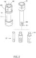
Fig. 2 is a breakdown drawing of a preferable embodiment of the present invention; -
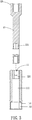
Fig. 3 is a partial cross-sectional view of a preferable embodiment of the present invention; -
Fig. 4 is a cross-sectional view of a preferable embodiment of the present invention in use; -
Fig. 5 is a partial enlargement ofFig. 4 . -
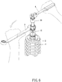
Fig. 6 is a schematic diagram of a preferable embodiment of the present invention in use. - Please refer to
Figs. 1 to 6 for a preferable embodiment of the present invention. A tool for anut 2 on ascrew 1 of a shock absorber of the present invention includes at least onesleeve 10 and arod member 20. - Each of the at least one
sleeve 10 includes a throughhole 11 and a connectingend 12 disposed around an end of the throughhole 11. Another end of thethrough hole 11 has amouth 13 which is enlarged and configured to be non-rotatably assembled with thenut 2. The connectingend 12 is configured to be relatively non-rotatably assembled with afirst torque tool 3. Therod member 20 includes a connectingrod 21 and at least onetool head 22 which is detachably assembled with an end of the connectingrod 21. Another end of the connectingrod 21 has an assemblingend 23 configured to be relatively non-rotatably assembled with asecond torque tool 4. Thetool head 22 is insertable into the throughhole 11 from the connectingend 12 to themouth 13, and therod member 20 is rotatable relative to thesleeve 10. Therefore, thetool head 22 is replaceable to be suitable for one of various nuts, and only onerod member 20 is needed. Thefirst torque tool 3 may be an open-end wrench, ring spanner, ratchet wrench, socket tool or the like. Thesecond torque tool 4 may be an open-end wrench, ring spanner, ratchet wrench, socket tool, Allen wrench or the like. - The through
hole 11 includes asmall diameter segment 111 which is communicated from the connectingend 12 to themouth 13. Thesmall diameter segment 111 is smaller than themouth 13 in diametrical dimension, and the connectingrod 21 is protrudable into themouth 13 no more than 1/4 depth of themouth 13 so that thetool head 22 is easy to be assembled and protrudes less beyond themouth 13. Agap 24 which is smaller than or equal to 0.5 mm is defined between the connectingrod 21 and thesmall diameter segment 111 so that the connectingrod 21 can be inserted smoothly into thesmall diameter segment 111 and the connectingrod 21 may be abutted against an inner wall of thesmall diameter segment 111 and not easy to sway during operation. - Specifically, the assembling
end 23 is larger than the throughhole 11 in diametrical dimension so that the connectingrod 21 can be accurately abutted against thesleeve 10 and thetool head 22 is located in a working position easy for operation. Themouth 13 includes an arcuate expandingsegment 131 extending laterally from thesmall diameter segment 111 and apolygonal segment 132 extending coaxially with thethrough hole 11. Anend surface 211 of the connectingrod 21 and a junction of thearcuate expanding segment 131 and thepolygonal segment 132 are on a same plane. Theend surface 211 of the connectingrod 21 has apolygonal assembling hole 212, and each of the at least onetool head 22 has apolygonal head 221 which is detachably assembled with thepolygonal assembling hole 212 so that thetool head 22 is replaceable according to one of various use requirements. In this embodiment, thepolygonal assembling hole 212 is a hexagonal hole and thepolygonal head 221 is a hexagonal head. When the connectingrod 21 is assembled with thesleeve 10, the hexagonal hole may be used directly without thetool head 22, and theend surface 211 of the connectingrod 21 protrudes beyond thesmall diameter segment 111 for easy assembly with thenut 2. However, the polygonal hole and the polygonal head may be configured to have other shapes. - The connecting
end 12 includes apolygonal hole 121 and a radial cross section of thepolygonal hole 121 is larger than that of thesmall diameter segment 111. Thepolygonal hole 121 includes a plurality ofwalls 122, and each of the plurality ofwalls 122 includes an arc concave 123 extending along a longitudinal direction of thesleeve 10. Each arc concave 123 is a part of a circle, and the circle and thesmall diameter segment 111 are coaxial and have a same diameter. Therefore, each arc concave 123 can support the connectingrod 21 stably when the connectingrod 21 is inserted into thesleeve 10, and thepolygonal hole 121 may be sized of small dimensions. A junction of the connectingrod 21 and thetool head 22 is located within thesmall diameter segment 111 when thetool head 22 is flush with themouth 13 so as to resist lateral stress and prevent thetool head 22 from departing from the connectingrod 21 during operation. - The
sleeve 10 further includes twoannular flanges 14 which are spacedly disposed and adjacent to the connectingend 12. The twoannular flanges 14 are configured to be engaged with a storage device and holed stably. Thefirst torque tool 3 can be rested on one of theannular flanges 14 to avoid movement along thesleeve 10 downward during operation. An inner wall of the connectingend 12 has at least onepositioning groove 124 and a peripheral surface of the connecting end has at least onepositioning groove 125. When thesleeve 10 is used individually, thesleeve 10 can be positionally assembled with a torque tool by the at least onepositioning groove - Preferably, a number of the at least one
sleeve 10 is plural and sizes or shapes of themouths 13 of the plurality ofsleeves 10 are different. A number of the at least onetool head 22 is plural and sizes or shapes of thetool heads 22 are different. An end away from the connectingrod 21 of each of thetool heads 22 includes a polygonal head or a polygonal hole. Therefore, thesleeve 10 with a required size is selected for operation according a specific requirement, and thetool head 22 is replaceable to be suitable for one of various sizes and shapes of thescrew 1 of the shock absorber and itsnut 2. - The invention further provides a method of operating the tool described above, including following steps of: assembling the
mouth 13 of one of thesleeve 10 with thenut 2; inserting therod member 20 into thesleeve 10, and assembling thetool head 22 with thescrew 1 or anothernut 2 on thescrew 1; non-rotatably assembling the first and thesecond torque tools end 12 and the assemblingend 23; rotating the first and thesecond torque tools figure 6 , in this embodiment, thesecond torque tool 4 is held to be stationary and thefirst torque tool 3 is rotated to disassemble or assemble thenut 2. The first torque tool may be held to be stationary and the second torque tool may be rotated, or the first and the second torque tools may be rotated in opposite direction. - Although particular embodiments of the invention have been described in detail for purposes of illustration, various modifications and enhancements may be made without departing from the spirit and scope of the invention. Accordingly, the invention is not to be limited except as by the appended claims.
Claims (15)
- A tool for a nut (2) on a screw (1) of a shock absorber, including:at least one sleeve (10), each of the at least one sleeve (10) including a through hole (11) and a connecting end (12) disposed around an end of the through hole (11), another end of the through hole (11) having a mouth (13) which is enlarged and configured to be non-rotatably assembled with the nut (2), the connecting end (12) being configured to be relatively non-rotatably assembled with a first torque tool (3);a rod member (20), including a connecting rod (21) and at least one tool head (22) which is detachably assembled with an end of the connecting rod (21), another end of the connecting rod (21) having an assembling end (23) configured to be relatively non-rotatably assembled with a second torque tool (4), the tool head (22) being insertable into the through hole (11) from the connecting end (12) to the mouth (13), and the rod member (20) being rotatable relative to the sleeve (10).
- The tool according to claim 1, wherein the through hole (11) includes a small diameter segment (111) which is communicated from the connecting end (12) to the mouth (13), the small diameter segment (111) is smaller than the mouth (13) in diametrical dimension, and the connecting rod (21) is protrudable into the mouth (13) no more than 1/4 depth of the mouth (13).
- The tool according to claim 2, wherein the connecting end (12) includes a polygonal hole (121), and a radial cross section of the polygonal hole (121) is larger than that of the small diameter segment (111).
- The tool according to claim 2 or 3, wherein a gap (24) which is smaller than or equal to 0.5 mm is defined between the connecting rod (21) and the small diameter segment (111).
- The tool according to any of the preceding claims, wherein the connecting rod (21) has a polygonal assembling hole (212), and each of the at least one tool head (22) has a polygonal head (221) which is detachably assembled with the polygonal assembling hole (212).
- The tool according to claim 5, wherein the polygonal assembling hole (212) is a hexagonal hole.
- The tool according to claim 2, wherein an end surface (211) of the connecting rod (21) has a hexagonal hole.
- The tool according to claim 2, wherein the assembling end (23) is larger than the through hole (11) in diametrical dimension, the mouth (13) includes an arcuate expanding segment (131) extending laterally from the small diameter segment (111) and a polygonal segment (132) extending coaxially with the through hole (11), and an end surface (211) of the connecting rod (21) and a junction of the arcuate expanding segment (131) and the polygonal segment (132) are on a same plane.
- The tool according to claim 3, wherein the polygonal hole (121) includes a plurality of walls (122), each of the plurality of walls (122) includes an arc concave (123) extending along a longitudinal direction of the sleeve (10), each arc concave (123) is a part of a circle, and the circle and the small diameter segment (111) are coaxial and have a same diameter.
- The according to claim 2, wherein a junction of the connecting rod (21) and the tool head (22) is located within the small diameter segment (111) when the tool head (22) is flush with the mouth (13).
- The tool according to any of the preceding claims, wherein the sleeve (10) further includes two annular flanges which are spacedly disposed and adjacent to the connecting end (12).
- The tool according to any of the preceding claims, wherein an inner wall of the connecting end (12) has at least one positioning groove (124).
- The tool according to claim 8, wherein the connecting end (12) includes a polygonal hole (121), a radial cross section of the polygonal hole (121) is larger than that of the small diameter segment (111); a gap (24) which is smaller than or equal to 0.5 mm is defined between the connecting rod (21) and the small diameter segment (111); the connecting rod (21) has a polygonal assembling hole (212), each of the at least one tool head (22) has a polygonal head (221) which is detachably assembled with the polygonal assembling hole (212); the polygonal assembling hole (212) is a hexagonal hole; the polygonal hole (121) includes a plurality of walls (122), each of the plurality of walls (122) includes an arc concave (123) extending along a longitudinal direction of the sleeve (10), each arc concave (123) is a part of a circle, the circle and the small diameter segment (111) are coaxial and have a same diameter; a junction of the connecting rod (21) and the tool head (22) is located within the small diameter segment (111) when the tool head (22) is flush with the mouth (13); the sleeve (10) further includes two annular flanges (14) which are spacedly disposed and adjacent to the connecting end (12); an inner wall of the connecting end (12) has at least one positioning groove (124); a peripheral surface of the connecting end (12) has at least one positioning groove (125).
- The tool according to any of the preceding claims, wherein a number of the at least one sleeve (10) is plural, sizes or shapes of the mouths (13) of the plurality of sleeves (10) are different; a number of the at least one tool head (22) is plural, sizes or shapes of the plurality of tool heads (22) are different, and an end away from the connecting rod (21) of each of the tool heads (22) includes a polygonal head (221) or a polygonal hole.
- A method of operating the tool according to any of the preceding claims, including following steps of:assembling the mouth (13) of one of the sleeve (10) with the nut (2);inserting the rod member (20) into the sleeve (10), and assembling the tool head (22) with the screw (1) or another nut (2) on the screw (1);non-rotatably assembling the first and the second torque tools (3,4) with the connecting end (12) and the assembling end (23) respectively;rotating the first and the second torque tools (3, 4) relatively.
Priority Applications (1)
| Application Number | Priority Date | Filing Date | Title |
|---|---|---|---|
| EP18188598.9A EP3608062A1 (en) | 2018-08-10 | 2018-08-10 | Tool for a nut on a screw of a shock absorber |
Applications Claiming Priority (1)
| Application Number | Priority Date | Filing Date | Title |
|---|---|---|---|
| EP18188598.9A EP3608062A1 (en) | 2018-08-10 | 2018-08-10 | Tool for a nut on a screw of a shock absorber |
Publications (1)
| Publication Number | Publication Date |
|---|---|
| EP3608062A1 true EP3608062A1 (en) | 2020-02-12 |
Family
ID=63407056
Family Applications (1)
| Application Number | Title | Priority Date | Filing Date |
|---|---|---|---|
| EP18188598.9A Withdrawn EP3608062A1 (en) | 2018-08-10 | 2018-08-10 | Tool for a nut on a screw of a shock absorber |
Country Status (1)
| Country | Link |
|---|---|
| EP (1) | EP3608062A1 (en) |
Cited By (1)
| Publication number | Priority date | Publication date | Assignee | Title |
|---|---|---|---|---|
| EP4186641A1 (en) | 2021-11-26 | 2023-05-31 | Volvo Truck Corporation | A tool for a nut on a threaded rod of a shock absorber |
Citations (6)
| Publication number | Priority date | Publication date | Assignee | Title |
|---|---|---|---|---|
| US4329892A (en) * | 1980-09-08 | 1982-05-18 | Daigle Vincent J | Shock-socket |
| US6598500B1 (en) * | 2001-08-20 | 2003-07-29 | Honda Giken Kogyo Kabushiki Kaisha | Double-nut tool and method of setting the toe angle of a vehicle wheel |
| CA2572701A1 (en) * | 2006-12-29 | 2008-06-29 | Honda Motor Co., Ltd. | Support assembly |
| US20100282031A1 (en) * | 2008-02-22 | 2010-11-11 | Mitsubisihi Heavy Industries, Ltd | Socket for socket wrench and method for fixing member to be fastened |
| CN203293094U (en) * | 2013-05-18 | 2013-11-20 | 奇瑞汽车股份有限公司 | Sliding column set assembling auxiliary tool |
| DE202018101990U1 (en) * | 2018-04-12 | 2018-05-18 | Stadtwerke Emden Gmbh | Tool for attaching end caps |
-
2018
- 2018-08-10 EP EP18188598.9A patent/EP3608062A1/en not_active Withdrawn
Patent Citations (6)
| Publication number | Priority date | Publication date | Assignee | Title |
|---|---|---|---|---|
| US4329892A (en) * | 1980-09-08 | 1982-05-18 | Daigle Vincent J | Shock-socket |
| US6598500B1 (en) * | 2001-08-20 | 2003-07-29 | Honda Giken Kogyo Kabushiki Kaisha | Double-nut tool and method of setting the toe angle of a vehicle wheel |
| CA2572701A1 (en) * | 2006-12-29 | 2008-06-29 | Honda Motor Co., Ltd. | Support assembly |
| US20100282031A1 (en) * | 2008-02-22 | 2010-11-11 | Mitsubisihi Heavy Industries, Ltd | Socket for socket wrench and method for fixing member to be fastened |
| CN203293094U (en) * | 2013-05-18 | 2013-11-20 | 奇瑞汽车股份有限公司 | Sliding column set assembling auxiliary tool |
| DE202018101990U1 (en) * | 2018-04-12 | 2018-05-18 | Stadtwerke Emden Gmbh | Tool for attaching end caps |
Cited By (1)
| Publication number | Priority date | Publication date | Assignee | Title |
|---|---|---|---|---|
| EP4186641A1 (en) | 2021-11-26 | 2023-05-31 | Volvo Truck Corporation | A tool for a nut on a threaded rod of a shock absorber |
Similar Documents
| Publication | Publication Date | Title |
|---|---|---|
| US6874984B2 (en) | Expansion bolt having internal spherical member and rear driving bolt | |
| US9352455B2 (en) | Fastener driver and extension | |
| US11090783B2 (en) | Offset torque drive apparatus and system | |
| CN1284023A (en) | Working tool | |
| US20140224084A1 (en) | Dutchman fastener removal tool | |
| US20120110815A1 (en) | Rivet Press | |
| EP2066478B1 (en) | Gripping device | |
| US20160138657A1 (en) | Driving head-changeable tool | |
| US10670056B2 (en) | Widener | |
| US8844409B2 (en) | Impact driver | |
| TWI635933B (en) | Socket tool | |
| AU2015202201B2 (en) | Fastener removal socket | |
| US12420388B2 (en) | Magnetic driving device | |
| US5762457A (en) | Threaded fastener with longitudinal grooves | |
| CN101619737A (en) | Bolt clamp device and special spanner | |
| CN111601682A (en) | Zero distance tool | |
| JP2019038052A (en) | Oil seal removal jig | |
| US11247315B2 (en) | Impact wrenches, wrench systems, and methods of use | |
| US11203097B2 (en) | Socket | |
| US20170291289A1 (en) | Connecting rod for an impact member of an impact tool | |
| CN207014267U (en) | The pneumatic Universal sleeve of high-performance | |
| US20150298302A1 (en) | Driving head-changeable tool | |
| CN106394116A (en) | Tyre replacing tool | |
| CN105014617B (en) | Tool with replaceable driving head | |
| CN211414943U (en) | percussion wrench |
Legal Events
| Date | Code | Title | Description |
|---|---|---|---|
| PUAI | Public reference made under article 153(3) epc to a published international application that has entered the european phase |
Free format text: ORIGINAL CODE: 0009012 |
|
| STAA | Information on the status of an ep patent application or granted ep patent |
Free format text: STATUS: REQUEST FOR EXAMINATION WAS MADE |
|
| 17P | Request for examination filed |
Effective date: 20181213 |
|
| AK | Designated contracting states |
Kind code of ref document: A1 Designated state(s): AL AT BE BG CH CY CZ DE DK EE ES FI FR GB GR HR HU IE IS IT LI LT LU LV MC MK MT NL NO PL PT RO RS SE SI SK SM TR |
|
| AX | Request for extension of the european patent |
Extension state: BA ME |
|
| STAA | Information on the status of an ep patent application or granted ep patent |
Free format text: STATUS: THE APPLICATION IS DEEMED TO BE WITHDRAWN |
|
| 18D | Application deemed to be withdrawn |
Effective date: 20220301 |