EP3608055A1 - Method for machining an optical surface of an optical lens - Google Patents
Method for machining an optical surface of an optical lens Download PDFInfo
- Publication number
- EP3608055A1 EP3608055A1 EP18306107.6A EP18306107A EP3608055A1 EP 3608055 A1 EP3608055 A1 EP 3608055A1 EP 18306107 A EP18306107 A EP 18306107A EP 3608055 A1 EP3608055 A1 EP 3608055A1
- Authority
- EP
- European Patent Office
- Prior art keywords
- lens
- machining device
- rotation axis
- machining
- blocker
- Prior art date
- Legal status (The legal status is an assumption and is not a legal conclusion. Google has not performed a legal analysis and makes no representation as to the accuracy of the status listed.)
- Granted
Links
Images

Classifications
-
- B—PERFORMING OPERATIONS; TRANSPORTING
- B24—GRINDING; POLISHING
- B24B—MACHINES, DEVICES, OR PROCESSES FOR GRINDING OR POLISHING; DRESSING OR CONDITIONING OF ABRADING SURFACES; FEEDING OF GRINDING, POLISHING, OR LAPPING AGENTS
- B24B13/00—Machines or devices designed for grinding or polishing optical surfaces on lenses or surfaces of similar shape on other work; Accessories therefor
- B24B13/01—Specific tools, e.g. bowl-like; Production, dressing or fastening of these tools
-
- B—PERFORMING OPERATIONS; TRANSPORTING
- B24—GRINDING; POLISHING
- B24B—MACHINES, DEVICES, OR PROCESSES FOR GRINDING OR POLISHING; DRESSING OR CONDITIONING OF ABRADING SURFACES; FEEDING OF GRINDING, POLISHING, OR LAPPING AGENTS
- B24B13/00—Machines or devices designed for grinding or polishing optical surfaces on lenses or surfaces of similar shape on other work; Accessories therefor
- B24B13/005—Blocking means, chucks or the like; Alignment devices
- B24B13/0055—Positioning of lenses; Marking of lenses
-
- B—PERFORMING OPERATIONS; TRANSPORTING
- B24—GRINDING; POLISHING
- B24B—MACHINES, DEVICES, OR PROCESSES FOR GRINDING OR POLISHING; DRESSING OR CONDITIONING OF ABRADING SURFACES; FEEDING OF GRINDING, POLISHING, OR LAPPING AGENTS
- B24B13/00—Machines or devices designed for grinding or polishing optical surfaces on lenses or surfaces of similar shape on other work; Accessories therefor
- B24B13/0031—Machines having several working posts; Feeding and manipulating devices
-
- B—PERFORMING OPERATIONS; TRANSPORTING
- B24—GRINDING; POLISHING
- B24B—MACHINES, DEVICES, OR PROCESSES FOR GRINDING OR POLISHING; DRESSING OR CONDITIONING OF ABRADING SURFACES; FEEDING OF GRINDING, POLISHING, OR LAPPING AGENTS
- B24B47/00—Drives or gearings; Equipment therefor
- B24B47/22—Equipment for exact control of the position of the grinding tool or work at the start of the grinding operation
-
- B—PERFORMING OPERATIONS; TRANSPORTING
- B24—GRINDING; POLISHING
- B24B—MACHINES, DEVICES, OR PROCESSES FOR GRINDING OR POLISHING; DRESSING OR CONDITIONING OF ABRADING SURFACES; FEEDING OF GRINDING, POLISHING, OR LAPPING AGENTS
- B24B9/00—Machines or devices designed for grinding edges or bevels on work or for removing burrs; Accessories therefor
- B24B9/02—Machines or devices designed for grinding edges or bevels on work or for removing burrs; Accessories therefor characterised by a special design with respect to properties of materials specific to articles to be ground
- B24B9/06—Machines or devices designed for grinding edges or bevels on work or for removing burrs; Accessories therefor characterised by a special design with respect to properties of materials specific to articles to be ground of non-metallic inorganic material, e.g. stone, ceramics, porcelain
- B24B9/08—Machines or devices designed for grinding edges or bevels on work or for removing burrs; Accessories therefor characterised by a special design with respect to properties of materials specific to articles to be ground of non-metallic inorganic material, e.g. stone, ceramics, porcelain of glass
- B24B9/14—Machines or devices designed for grinding edges or bevels on work or for removing burrs; Accessories therefor characterised by a special design with respect to properties of materials specific to articles to be ground of non-metallic inorganic material, e.g. stone, ceramics, porcelain of glass of optical work, e.g. lenses, prisms
Definitions
- the invention relates to a method for machining an optical surface of an optical lens, a machining device for machining the optical surface of an optical lens, and to a computer program product comprising one or more stored sequences of instructions corresponding to the method of the invention.
- An optical lens is typically made of plastic or glass material and generally has two opposing surfaces which co-operate with one another to converge or diverge light according to a required corrective prescription.
- optical lens In addition to the precision in manufacturing the surfaces, it is also essential for such surfaces to be perfectly aligned with one another both axially and angularly. Otherwise, the optical lens does not provide the optical effect for which it was designed, in particular the required corrective prescription.
- Manufacturing of an optical lens to the required prescription requirements typically includes machining the surface of a semi-finished lens or lens blank.
- a semi-finished lens has a finished front surface and an unfinished back surface.
- Further surfacing operations of an optical lens can include chamfering, beveling, polishing, or coating the surface of a lens member in order to modify the optical surface.
- the semi-finished lens is securely maintained in a correct positioning.
- the semi-finished lens in order to hold in position, the semi-finished lens a lens blocker is used that is applied to the finished front surface at a precise angular and axial position.
- the lens blocker acts as a gripping interface for the holding system during the manufacturing of the surface to be manufactured in particular during the cutting step and provides the semi-finished lens blank with a sufficient strength to counteract the force applied by the cutting tool.
- the desired prism may be either a prescription prism or a thinning prism.
- the prism of the optical lens can be defined by the vector ( ⁇ f, ⁇ f, Zf) which is perpendicular to the tangential plan at the prism reference point (PRP) of the optical lens; whereby ⁇ f corresponds to the prism amplitude, ⁇ f correspondents to the prism orientation and Zf the vertical position of the PRP.
- the manufacturing of such desired prism requires that the semi-finished lens be oriented in a desired specific orientation with respect to the manufacturing tools.
- Such orientation is usually obtained by using a prismatic blocker enabling the semi-finished lens blank to be supported at a given inclination or tilt for the machining process.
- Prismatic blockers typically require the use of resins or glues, therefore requiring long times to allow the adhesive material to set and cool down.
- the prism at blocking is applied through a lead-based low melting alloy.
- One object of the present invention is to provide such method.
- the invention proposes a method for machining an optical surface of an optical lens, the method comprising:
- the method of the invention combines a tilting step and a surface position determining step allowing to machine an optical lens with a desired prism without the use of a prismatic blocker.
- the semi-finished lens blank may be blocked to a simple lens blocker and the desired prism may be managed entirely during the machining step and in the machining device.
- the invention also relates to a machining device for machining the optical surface of an optical lens, the machining device comprising:
- the invention further relates to a computer program product comprising one or more stored sequences of instructions that are stored, for instance, on a non-transitory computer memory and that are accessible to a processor and which, when executed by the processor, causes the processor to carry out at least the steps of the method according to the invention.
- the invention also relates to a computer-readable storage medium having a program recorded thereon; where the program makes the computer execute at least the steps of the method of the invention.
- the invention further relates to a computer readable medium comprising one or more stored sequences of instruction of a computer program product, wherein the one or more sequences of instructions are accessible to a processor and which, when executed by the processor, causes the processor to carry out the steps of the method according to the invention.
- the invention relates to a method for machining an optical surface of an optical lens starting from a lens blank.
- the method of the invention comprises at least:
- a lens blank blocked on a lens blocker is provided.
- the lens blank may be a semi-finished optical lens member.
- the lens blank may require that both surfaces be machined.
- Opposing surface 12 is machined by a machining tool so that the back surface 13 is orientated with respect to and distanced from the front surface 11, according to the required optical prescription.
- optical surface 13 to be manufactured is represented in Figure 2 as concave, it is to be appreciated that the optical surface 13 could equally well be convex or any other curved surface
- reference manufacturing markings 111 may be provided on the preformed front surface 11 of the semi-finished lens member 10 as reference features for positioning purposes. The manufacturing markings 111 are visible through the semi-finished lens member 10 from the opposing side 12 of the lens member 10.
- a lens blocking device 20 for blocking lens member 10 in the correct positioning for manufacturing processes comprises a blocker 21, a blocking ring 22.
- a protection film may be placed between the front surface 11 of the lens member 10 and the blocking device 20.
- Blocking cast material 24 is poured into the cavity defined by the lower front surface 11 of the optical lens 10, the blocker 21 and the blocking ring 22.
- the blocking cast material 24 cools to solidify in order to provide a blocking support for the optical lens 10 at the desired positioning for machining.
- the lower surface or bearing surface 241 of blocking material 241 acts as a reference surface for determining the thickness at the center of the lens member 10.
- the lens blocking device may also be a vacuum blocking device wherein the semi-finished lens member is blocked against a blocking device using a vacuum.
- the blocking device comprises a suction device.
- a suction device preferably comprises a first rotary shaft or rear mandrel ending with a suction chamber at the end intended to come into contact with the front surface of the semi-finished optical lens member blank.
- the suction chamber is connected to a suction group for generating the vacuum and comprises a gasket or other type of sealing elements capable of making a fluid tight coupling once such sealing elements are rested onto the front surface of the semi-finished optical lens member.
- the lens blocker holding the lens blank is clamped in a lens machining device.
- the lens blocker 21 holding the lens blank 10 may be clamped using a clamping device 30, such as a clamp so as to allow the rotation of the lens blocker holding the lens blank about a rotation axis of the machining device.
- the lens blank 10 and the lens blocker are tilted relative to the rotation axis 40 of the lens machining device during the tilting step S3.
- tilting the lens blocker in the lens machining device allows machining a desired prism without having to carry out a complex blocking process.
- the lens blank may be blocked without considering a desired prism.
- the lens blank and lens blocker are tilted of a tilt angle ⁇ with the rotation axis of the lens machining device.
- the angle ⁇ is smaller than or equal to 3°.
- the position of the surface 13 to be machined is determined during the surface position determining step S4.
- the position of the surface 13 to be machined is determined based on the tilt angle ⁇ of the lens blank and the lens blocker relative to the rotation axis of the lens machining device.
- the position of the surface to be machined is determined so that the angle ⁇ between the normal of the surface to be machined at the rotation axis of the lens machining device and the rotation axis of the lens machining device is smaller than or equal to 3°.
- the angle ⁇ between the normal of the surface to be machined at the rotation axis of the lens machining device and the rotation axis of the lens machining device is to be as small as possible.
- the position of the surface to be machined is determined so that the normal of the surface to be machined at the rotation axis of the lens machining device is co-linear with the rotation axis of the lens machining device.
- the position of the surface 13 to be machined is positioned so that the angle ⁇ is a small as possible.
- the surface 13 to be machined is positioned so that the normal of the surface to be machined 60 at the rotation axis of the lens machining device is co-linear with the rotation axis of the lens machining device.
- the lens blank and lens blocker are tilted of an angle ⁇ determined so as the difference with the angle ⁇ between the normal of the surface to be machined at the rotation axis of the lens machining device and the rotation axis of the lens machining device is as small as possible.
- the method of the invention may comprise an optimization process so as to determine the tilt angle and the position of the surface to be machined so that both angles ⁇ and ⁇ to be both as small as possible and as close as possible one from the other.
- the operational parameters of the lens machining tool are configured in order to manufacture the surface to be machined according to the determined surface position so that the desired optical properties of the optical lens are respected.
- the skilled person may use any know method to determine the operational parameters depending on the type and shape of the machining tool.
- the method according to the invention may further comprise a surface machining step S6.
- the surface of the optical lens blank to be machined is machined based on the operational parameters of the lens machining tool configured during the machining tool configuration step.
- the clamping and tilting steps may be carried out simultaneously by having the clamping device of the machining device with a predetermined tilt relative to the rotation axis of the lens machining device.
- a predetermined tilt relative to the rotation axis of the lens machining device is easier to implement for the machining operator.
- the desired prism may than be adjusted by positioning the surface 13 to be machined during the surface positioning step S4.
- the method of the invention may further comprise a weight distribution determining step S31.
- a weight distribution of the lens blank and lens blocker around the rotation axis of the lens machining device is determined based on the tilt of the lens blank and lens blocker.
- the weight distribution is determined so as to reduce the effect of the centrifugal force that may apply to the lens blank when rotated about the rotation axis 40 when the weight distribution is not homogeneous.
- a weight distribution of the lens blank and lens blocker around the rotation axis of the lens machining device is determined so as to have a weight distribution as homogeneous as possible around the rotation axis 40 of the machining device.
- addition weights may be added to the lens blocker to as to homogenize the weight distribution around the axis of rotation reducing the stress applied to the rotation axis.
- the invention further relates to a machining device for machining the optical surface of an optical lens.
- the machining device comprising at least a clamp 30, a processor 70 and a machining tool 80.
- the machining device represented diagrammatically in figure 6 is adapted to drive in rotation about an axis 40 a lens blank 10 that is blocked on a lens blocker.
- the lens blocker is hold by a clamp 30 and tilted relative to the axis 40.
- the machining device also drives movement in the directions 81 and 82 of a tool-carrier 80 to which a machining tool 83 is fixed.
- the machining device may be adapted to machine with the tool 83 a surface with a constant depth of pass over the surface 12 of the lens blank.
- the machining device may synchronize the position of the tool 83 and the angular position of the lens blank in the direction 82 to follow the shape of the surface 12 and to apply the required depth of pass to it, in addition to its forward movement in the direction 81.
- the clamp 30 is configure to clamp a lens blocker with a tilt angle relative to the rotation axis of the lens machining device.
- the clamp may have a predetermined tilt angle relative to the rotation axis of the lens machining device, for example smaller than or equal to 3°.
- the clamp may be configured to tilt the lens blank and lens blocker with an angle ⁇ , for example smaller than or equal to 3°.
- the processor 70 is configured to determine the position of the surface to be machined based on the tilt angle of the lens blank and lens blocker relative to the rotation axis of the lens machining device.
- the processor 70 is configured to determine the operational parameters of the lens machining tool 80 in order to manufacture the surface to be manufactured according to the determined surface position so that the desired optical properties of the optical lens are respected.
- the processor 70 may further be configured to determine a weight distribution of the lens blank and lens blocker around the rotation axis of the lens machining device based on the tilt of the lens blank and lens blocker.
Landscapes
- Engineering & Computer Science (AREA)
- Mechanical Engineering (AREA)
- Grinding And Polishing Of Tertiary Curved Surfaces And Surfaces With Complex Shapes (AREA)
- Turning (AREA)
Abstract
- a lens blank providing step, during which a lens blank blocked on a lens blocker is provided,
- a clamping step, during which the lens blocker holding the lens blank is clamped in a lens machining device,
- a tilting step, during which the lens blank and lens blocker are tilted relative to the rotation axis of the lens machining device,
- a surface position determining step, during which the position of the surface to be machined is determined based on the tilt angle of the lens blank and lens blocker relative to the rotation axis of the lens machining device,
- a machining tool configuration step, during which the operational parameters of the lens machining tool are configured in order to manufacture the surface to be manufactured according to the determined surface position so that the desired optical properties of the optical lens are respected.
Description
- The invention relates to a method for machining an optical surface of an optical lens, a machining device for machining the optical surface of an optical lens, and to a computer program product comprising one or more stored sequences of instructions corresponding to the method of the invention.
- An optical lens is typically made of plastic or glass material and generally has two opposing surfaces which co-operate with one another to converge or diverge light according to a required corrective prescription.
- During the machining of an optical lens, in addition to the precision in manufacturing the surfaces, it is also essential for such surfaces to be perfectly aligned with one another both axially and angularly. Otherwise, the optical lens does not provide the optical effect for which it was designed, in particular the required corrective prescription.
- Indeed, the relative positioning and shape of these surfaces has a direct impact on the effect of the optical lens on light.
- Manufacturing of an optical lens to the required prescription requirements typically includes machining the surface of a semi-finished lens or lens blank. Typically, a semi-finished lens has a finished front surface and an unfinished back surface. By machining the back surface of the lens to remove material, the required shape and positioning of the back surface with respect to the front surface for the desired corrective prescription can be generated. Further surfacing operations of an optical lens can include chamfering, beveling, polishing, or coating the surface of a lens member in order to modify the optical surface.
- During manufacturing of the lens, it is important that the semi-finished lens is securely maintained in a correct positioning.
- In the state of the art, in order to hold in position, the semi-finished lens a lens blocker is used that is applied to the finished front surface at a precise angular and axial position.
- The lens blocker acts as a gripping interface for the holding system during the manufacturing of the surface to be manufactured in particular during the cutting step and provides the semi-finished lens blank with a sufficient strength to counteract the force applied by the cutting tool.
- During the manufacturing process of an optical lens a desired prism may be introduced. The desired prism may be either a prescription prism or a thinning prism.
- The prism of the optical lens can be defined by the vector (αf, βf, Zf) which is perpendicular to the tangential plan at the prism reference point (PRP) of the optical lens; whereby αf corresponds to the prism amplitude, βf correspondents to the prism orientation and Zf the vertical position of the PRP.
- The manufacturing of such desired prism requires that the semi-finished lens be oriented in a desired specific orientation with respect to the manufacturing tools. Such orientation is usually obtained by using a prismatic blocker enabling the semi-finished lens blank to be supported at a given inclination or tilt for the machining process.
- Prismatic blockers typically require the use of resins or glues, therefore requiring long times to allow the adhesive material to set and cool down. Alternatively, the prism at blocking is applied through a lead-based low melting alloy.
- Therefore, there is a need for a method of machining an optical lens that allows having a desired prism that would not present the prior art method drawbacks.
- One object of the present invention is to provide such method.
- To this end, the invention proposes a method for machining an optical surface of an optical lens, the method comprising:
- a lens blank providing step, during which a lens blank blocked on a lens blocker is provided,
- a clamping step, during which the lens blocker holding the lens blank is clamped in a lens machining device,
- a tilting step, during which the lens blank and lens blocker are tilted relative to the rotation axis of the lens machining device,
- a surface position determining step, during which the position of the surface to be machined is determined based on the tilt angle of the lens blank and lens blocker relative to the rotation axis of the lens machining device,
- a machining tool configuration step, during which the operational parameters of the lens machining tool are configured in order to manufacture the surface to be manufactured according to the determined surface position so that the desired optical properties of the optical lens are respected.
- Advantageously, the method of the invention combines a tilting step and a surface position determining step allowing to machine an optical lens with a desired prism without the use of a prismatic blocker.
- Therefore, the semi-finished lens blank may be blocked to a simple lens blocker and the desired prism may be managed entirely during the machining step and in the machining device.
- According to further embodiments which can be considered alone or in combination:
- during the surface position determining step the position of the surface to be machined is determined so that the angle α between the normal of the surface to be machined at the rotation axis of the lens machining device and the rotation axis of the lens machining device is smaller than or equal to 3°; and/or
- during the surface position determining step the position of the surface to be machined is determined so that the normal of the surface to be machined at the rotation axis of the lens machining device is co-linear with the rotation axis of the lens machining device; and/or
- during the tilting step the lens blank and lens blocker are tilted of an angle β with the rotation axis of the lens machining device smaller than or equal to 3°; and/or
- the method further comprises a weight distribution determining step during which a weight distribution of the lens blank and lens blocker around the rotation axis of the lens machining device is determined based on the tilt of the lens blank and lens blocker; and/or
- the tilting step the lens blank and lens blocker are tilted so that the angle α between the normal of the surface to be machined at the rotation axis of the lens machining device and the rotation axis of the lens machining device is as small as possible; and/or
- during the tilting step the lens blank and lens blocker are tilted of an angle β determined so as the difference with the angle α between the normal of the surface to be machined at the rotation axis of the lens machining device and the rotation axis of the lens machining device is as small as possible; and/or
- the clamping and tilting steps are carried out simultaneously by having the clamping device of the machining device with a predetermined tilt relative to the rotation axis of the lens machining device; and/or
- the method further comprises a surface machining step during which the surface of the optical lens blank to be machined is machined based on the operational parameters of the lens machining tool configured during the machining tool configuration step.
- The invention also relates to a machining device for machining the optical surface of an optical lens, the machining device comprising:
- a clamp configure to clamp a lens blocker with a tilt angle relative to the rotation axis of the lens machining device, and
- a processor for:
- determining the position of the surface to be machined based on the tilt angle of the lens blank and lens blocker relative to the rotation axis of the lens machining device, and
- configuring the operational parameters of the lens machining tool in order to manufacture the surface to be manufactured according to the determined surface position so that the desired optical properties of the optical lens are respected.
- According to further embodiments which can be considered alone or in combination:
- the clamp has a predetermined tilt angle relative to the rotation axis of the lens machining device; and/or
- the clamp is configured to tilt the lens blank and lens blocker with an angle β smaller than or equal to 3°; and/or
- the processor is further configured to determine a weight distribution of the lens blank and lens blocker around the rotation axis of the lens machining device based on the tilt of the lens blank and lens blocker.
- The invention further relates to a computer program product comprising one or more stored sequences of instructions that are stored, for instance, on a non-transitory computer memory and that are accessible to a processor and which, when executed by the processor, causes the processor to carry out at least the steps of the method according to the invention.
- The invention also relates to a computer-readable storage medium having a program recorded thereon; where the program makes the computer execute at least the steps of the method of the invention.
- The invention further relates to a device comprising a processor adapted to store one or more sequence of instructions and to carry out at least steps of the method according to the invention.
- The invention further relates to a computer readable medium comprising one or more stored sequences of instruction of a computer program product, wherein the one or more sequences of instructions are accessible to a processor and which, when executed by the processor, causes the processor to carry out the steps of the method according to the invention.
- Embodiments of the invention will now be described, by way of example only, and with reference to the following drawings in which:
-
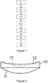
Figure 1 is a flow chart representing a method according to the invention, -
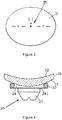
Figure 2 is a perspective view of a lens blank to be machined, -
Figure 3 is a planar view of a preformed surface of a lens blank to be machined, -
Figure 4 is a cross-sectional view of a lens blank blocked on a lens blocker, -
Figure 5 is a cross-sectional view of a lens blank blocked on a lens blocker and clamped in a lens machining device, and -
Figure 6 is a schematic representation of a machining device adapted to move a machining tool so that it cooperates in a turning operation with lens blank that is driven in rotation. - Elements in the figures are illustrated for simplicity and clarity and have not necessarily been drawn to scale. For example, the dimensions of some of the elements in the figure may be exaggerated relative to other elements to help improve the understanding of the embodiments of the present invention.
- The invention relates to a method for machining an optical surface of an optical lens starting from a lens blank.
- As illustrated on
figure 1 , the method of the invention comprises at least: - a lens blank providing step S1,
- a clamping step S2,
- a tilting step S3,
- a surface position determining step S4, and
- a machining tool configuration step S5.
- During the lens blank providing step S1 a lens blank blocked on a lens blocker is provided.
- The lens blank may be a semi-finished optical lens member. Alternatively, the lens blank may require that both surfaces be machined.
- As illustrated on
figure 2 , asemi-finished lens member 10 has a preformedfront surface 11 that, in use of the resulting finished optical lens, is disposed nearest the object being viewed and an opposingsurface 12 to be modified by the manufacturing process to provide theback surface 13 of the finished optical lens, represented by the dotted line. - Opposing
surface 12 is machined by a machining tool so that theback surface 13 is orientated with respect to and distanced from thefront surface 11, according to the required optical prescription. - While in this embodiment of the invention, the back surface of the optical lens is formed by the machining process, it is to be understood, that in alternative embodiments of the invention both or either surfaces of the lens may be formed by the machining process.
- Moreover, although the
optical surface 13 to be manufactured is represented inFigure 2 as concave, it is to be appreciated that theoptical surface 13 could equally well be convex or any other curved surface - With reference to
Figure 3 ,reference manufacturing markings 111 may be provided on the preformedfront surface 11 of thesemi-finished lens member 10 as reference features for positioning purposes. Themanufacturing markings 111 are visible through thesemi-finished lens member 10 from the opposingside 12 of thelens member 10. - Referring now to
Figure 4 and5 , alens blocking device 20 for blockinglens member 10 in the correct positioning for manufacturing processes comprises ablocker 21, a blockingring 22. A protection film, not represented, may be placed between thefront surface 11 of thelens member 10 and the blockingdevice 20. Blockingcast material 24 is poured into the cavity defined by the lowerfront surface 11 of theoptical lens 10, theblocker 21 and the blockingring 22. The blockingcast material 24 cools to solidify in order to provide a blocking support for theoptical lens 10 at the desired positioning for machining. The lower surface or bearingsurface 241 of blockingmaterial 241 acts as a reference surface for determining the thickness at the center of thelens member 10. - The lens blocking device may also be a vacuum blocking device wherein the semi-finished lens member is blocked against a blocking device using a vacuum.
- Typically, the blocking device comprises a suction device. Such a device preferably comprises a first rotary shaft or rear mandrel ending with a suction chamber at the end intended to come into contact with the front surface of the semi-finished optical lens member blank. The suction chamber is connected to a suction group for generating the vacuum and comprises a gasket or other type of sealing elements capable of making a fluid tight coupling once such sealing elements are rested onto the front surface of the semi-finished optical lens member.
- During the clamping step S2, the lens blocker holding the lens blank is clamped in a lens machining device. As illustrated on
figure 5 , thelens blocker 21 holding thelens blank 10 may be clamped using aclamping device 30, such as a clamp so as to allow the rotation of the lens blocker holding the lens blank about a rotation axis of the machining device. - As illustrated on
figure 6 , thelens blank 10 and the lens blocker are tilted relative to therotation axis 40 of the lens machining device during the tilting step S3. - Advantageously, tilting the lens blocker in the lens machining device allows machining a desired prism without having to carry out a complex blocking process. Indeed, the lens blank may be blocked without considering a desired prism. Thus, making the blocking step much easier and allowing an easy use of for example vacuum blocking devices.
- During the tilting step S3, the lens blank and lens blocker are tilted of a tilt angle β with the rotation axis of the lens machining device. According to an embodiment of the invention, the angle β is smaller than or equal to 3°.
- The position of the
surface 13 to be machined is determined during the surface position determining step S4. The position of thesurface 13 to be machined is determined based on the tilt angle β of the lens blank and the lens blocker relative to the rotation axis of the lens machining device. - According to a preferred embodiment of the invention, during the surface position determining step S4, the position of the surface to be machined is determined so that the angle α between the normal of the surface to be machined at the rotation axis of the lens machining device and the rotation axis of the lens machining device is smaller than or equal to 3°.
- So as to facilitate the machining of the surface and to increase the quality of the machined surface, the angle α between the normal of the surface to be machined at the rotation axis of the lens machining device and the rotation axis of the lens machining device is to be as small as possible.
- Therefore, according to an embodiment of the invention, during the surface position determining step the position of the surface to be machined is determined so that the normal of the surface to be machined at the rotation axis of the lens machining device is co-linear with the rotation axis of the lens machining device.
- In addition, or alternatively, during the surface position determining step the position of the
surface 13 to be machined is positioned so that the angle β is a small as possible. For example, thesurface 13 to be machined is positioned so that the normal of the surface to be machined 60 at the rotation axis of the lens machining device is co-linear with the rotation axis of the lens machining device. - According to an embodiment of the invention, during the tilting step the lens blank and lens blocker are tilted of an angle β determined so as the difference with the angle α between the normal of the surface to be machined at the rotation axis of the lens machining device and the rotation axis of the lens machining device is as small as possible.
- The method of the invention may comprise an optimization process so as to determine the tilt angle and the position of the surface to be machined so that both angles α and β to be both as small as possible and as close as possible one from the other.
- During the machining tool configuration step, the operational parameters of the lens machining tool are configured in order to manufacture the surface to be machined according to the determined surface position so that the desired optical properties of the optical lens are respected.
- The skilled person may use any know method to determine the operational parameters depending on the type and shape of the machining tool.
- As illustrated on
figure 1 , the method according to the invention may further comprise a surface machining step S6. - During the surface machining step S6, the surface of the optical lens blank to be machined is machined based on the operational parameters of the lens machining tool configured during the machining tool configuration step.
- According to an embodiment of the invention, the clamping and tilting steps may be carried out simultaneously by having the clamping device of the machining device with a predetermined tilt relative to the rotation axis of the lens machining device. Advantageously, such embodiment is easier to implement for the machining operator.
- The desired prism may than be adjusted by positioning the
surface 13 to be machined during the surface positioning step S4. - As illustrated on
figure 1 , the method of the invention may further comprise a weight distribution determining step S31. - During the weight distribution determining step S31, a weight distribution of the lens blank and lens blocker around the rotation axis of the lens machining device is determined based on the tilt of the lens blank and lens blocker. Preferably the weight distribution is determined so as to reduce the effect of the centrifugal force that may apply to the lens blank when rotated about the
rotation axis 40 when the weight distribution is not homogeneous. - According to an embodiment of the invention, during the weight distribution determining step S31, a weight distribution of the lens blank and lens blocker around the rotation axis of the lens machining device is determined so as to have a weight distribution as homogeneous as possible around the
rotation axis 40 of the machining device. - For example, depending on the tilt angle and the surface to be machined, addition weights may be added to the lens blocker to as to homogenize the weight distribution around the axis of rotation reducing the stress applied to the rotation axis.
- The invention further relates to a machining device for machining the optical surface of an optical lens. As illustrated on
Figure 6 , the machining device comprising at least aclamp 30, aprocessor 70 and amachining tool 80. - The machining device represented diagrammatically in
figure 6 is adapted to drive in rotation about an axis 40 alens blank 10 that is blocked on a lens blocker. The lens blocker is hold by aclamp 30 and tilted relative to theaxis 40. - The machining device also drives movement in the
directions 81 and 82 of a tool-carrier 80 to which amachining tool 83 is fixed. - According to an embodiment, the machining device may be adapted to machine with the tool 83 a surface with a constant depth of pass over the
surface 12 of the lens blank. To this end, the machining device may synchronize the position of thetool 83 and the angular position of the lens blank in the direction 82 to follow the shape of thesurface 12 and to apply the required depth of pass to it, in addition to its forward movement in thedirection 81. - The
clamp 30 is configure to clamp a lens blocker with a tilt angle relative to the rotation axis of the lens machining device. - According to an embodiment, the clamp may have a predetermined tilt angle relative to the rotation axis of the lens machining device, for example smaller than or equal to 3°.
- Alternatively, the clamp may be configured to tilt the lens blank and lens blocker with an angle β, for example smaller than or equal to 3°.
- The
processor 70 is configured to determine the position of the surface to be machined based on the tilt angle of the lens blank and lens blocker relative to the rotation axis of the lens machining device. - Furthermore, the
processor 70 is configured to determine the operational parameters of thelens machining tool 80 in order to manufacture the surface to be manufactured according to the determined surface position so that the desired optical properties of the optical lens are respected. - According to an embodiment of the invention, the
processor 70 may further be configured to determine a weight distribution of the lens blank and lens blocker around the rotation axis of the lens machining device based on the tilt of the lens blank and lens blocker. - The invention has been described above with the aid of embodiments without limitation of the general inventive concept.
- Many further modifications and variations will suggest themselves to those skilled in the art upon making reference to the foregoing illustrative embodiments, which are given by way of example only and which are not intended to limit the scope of the invention, that being determined solely by the appended claims.
- In the claims, the word "comprising" does not exclude other elements or steps, and the indefinite article "a" or "an" does not exclude a plurality. The mere fact that different features are recited in mutually different dependent claims does not indicate that a combination of these features cannot be advantageously used. Any reference signs in the claims should not be construed as limiting the scope of the invention.
Claims (15)
- Method for machining an optical surface of an optical lens, the method comprising:- a lens blank providing step, during which a lens blank blocked on a lens blocker is provided,- a clamping step, during which the lens blocker holding the lens blank is clamped in a lens machining device,- a tilting step, during which the lens blank and lens blocker are tilted relative to the rotation axis of the lens machining device,- a surface position determining step, during which the position of the surface to be machined is determined based on the tilt angle of the lens blank and lens blocker relative to the rotation axis of the lens machining device,- a machining tool configuration step, during which the operational parameters of the lens machining tool are configured in order to manufacture the surface to be manufactured according to the determined surface position so that the desired optical properties of the optical lens are respected.
- The method according to claim 1, wherein during the surface position determining step the position of the surface to be machined is determined so that the angle α between the normal of the surface to be machined at the rotation axis of the lens machining device and the rotation axis of the lens machining device is smaller than or equal to 3°.
- The method according to claim 1 or 2, wherein during the surface position determining step the position of the surface to be machined is determined so that the normal of the surface to be machined at the rotation axis of the lens machining device is co-linear with the rotation axis of the lens machining device.
- The method according to any of the preceding claims, wherein during the tilting step the lens blank and lens blocker are tilted of an angle β with the rotation axis of the lens machining device smaller than or equal to 3°.
- The method according to any of the preceding claims, wherein the method further comprises a weight distribution determining step during which a weight distribution of the lens blank and lens blocker around the rotation axis of the lens machining device is determined based on the tilt of the lens blank and lens blocker.
- The method according to any of the preceding claims, wherein during the tilting step the lens blank and lens blocker are tilted so that the angle α between the normal of the surface to be machined at the rotation axis of the lens machining device and the rotation axis of the lens machining device is as small as possible.
- The method according to any of the preceding claims, wherein during the tilting step the lens blank and lens blocker are tilted of an angle β determined so as the difference with the angle α between the normal of the surface to be machined at the rotation axis of the lens machining device and the rotation axis of the lens machining device is as small as possible.
- The method according to any of claims 1 to 5, wherein the clamping and tilting steps are carried out simultaneously by having the clamping device of the machining device with a predetermined tilt relative to the rotation axis of the lens machining device.
- The method according to any of the preceding claims, further comprising a surface machining step during which the surface of the optical lens blank to be machined is machined based on the operational parameters of the lens machining tool configured during the machining tool configuration step.
- Machining device for machining the optical surface of an optical lens, the machining device comprising:- a clamp configure to clamp a lens blocker with a tilt angle relative to the rotation axis of the lens machining device, and- a processor fordetermining the position of the surface to be machined based on the tilt angle of the lens blank and lens blocker relative to the rotation axis of the lens machining device, andconfiguring the operational parameters of the lens machining tool in order to manufacture the surface to be manufactured according to the determined surface position so that the desired optical properties of the optical lens are respected.
- The machining device according to claim 10, wherein the clamp has a predetermined tilt angle relative to the rotation axis of the lens machining device.
- The machining device according to claim 10, wherein the clamp is configured to tilt the lens blank and lens blocker with an angle β smaller than or equal to 3°.
- The machining device according to any of claims 10 to 12, wherein the processor is further configured to determine a weight distribution of the lens blank and lens blocker around the rotation axis of the lens machining device based on the tilt of the lens blank and lens blocker.
- A computer program product for a data processing device, the computer program product comprising a set of instructions which, when loaded into the data processing device, causes the data processing device to perform at least the surface position and machining steps of the method of any one of claims 1 to 9.
- A computer readable medium carrying one or more sequences of instructions of the computer program product of claim 14.
Priority Applications (7)
| Application Number | Priority Date | Filing Date | Title |
|---|---|---|---|
| EP18306107.6A EP3608055B1 (en) | 2018-08-10 | 2018-08-10 | Method for machining an optical surface of an optical lens |
| PT183061076T PT3608055T (en) | 2018-08-10 | 2018-08-10 | Method for machining an optical surface of an optical lens |
| HUE18306107A HUE066310T2 (en) | 2018-08-10 | 2018-08-10 | Method for machining an optical surface of an optical lens |
| PL18306107.6T PL3608055T3 (en) | 2018-08-10 | 2018-08-10 | Method for machining an optical surface of an optical lens |
| PCT/EP2019/071375 WO2020030764A1 (en) | 2018-08-10 | 2019-08-08 | Method for machining an optical surface of an optical lens |
| US17/267,145 US20210308818A1 (en) | 2018-08-10 | 2019-08-08 | Method for machining an optical surface of an optical lens |
| CN201980052700.6A CN112533729B (en) | 2018-08-10 | 2019-08-08 | Method for machining optical surfaces of optical lenses |
Applications Claiming Priority (1)
| Application Number | Priority Date | Filing Date | Title |
|---|---|---|---|
| EP18306107.6A EP3608055B1 (en) | 2018-08-10 | 2018-08-10 | Method for machining an optical surface of an optical lens |
Publications (2)
| Publication Number | Publication Date |
|---|---|
| EP3608055A1 true EP3608055A1 (en) | 2020-02-12 |
| EP3608055B1 EP3608055B1 (en) | 2024-01-24 |
Family
ID=63311950
Family Applications (1)
| Application Number | Title | Priority Date | Filing Date |
|---|---|---|---|
| EP18306107.6A Active EP3608055B1 (en) | 2018-08-10 | 2018-08-10 | Method for machining an optical surface of an optical lens |
Country Status (7)
| Country | Link |
|---|---|
| US (1) | US20210308818A1 (en) |
| EP (1) | EP3608055B1 (en) |
| CN (1) | CN112533729B (en) |
| HU (1) | HUE066310T2 (en) |
| PL (1) | PL3608055T3 (en) |
| PT (1) | PT3608055T (en) |
| WO (1) | WO2020030764A1 (en) |
Cited By (1)
| Publication number | Priority date | Publication date | Assignee | Title |
|---|---|---|---|---|
| EP4477354A1 (en) | 2023-06-13 | 2024-12-18 | Satisloh AG | Device for retaining an optical workpiece for processing/treatment thereof and method for retaining an optical workpiece at such a device |
Families Citing this family (1)
| Publication number | Priority date | Publication date | Assignee | Title |
|---|---|---|---|---|
| EP4501539B1 (en) * | 2023-08-03 | 2025-12-17 | Carl Zeiss Vision International GmbH | Arrangement for a spectacle lens blocking system, calibration cylinder, method for cali-brating a spectacle lens blockings system, method of manufacturing a spectacle lens and computer program product |
Citations (5)
| Publication number | Priority date | Publication date | Assignee | Title |
|---|---|---|---|---|
| GB656875A (en) * | 1939-10-11 | 1951-09-05 | American Optical Corp | Improvements in or relating to multifocal or bifocal lenses and to their manufacture |
| US2573668A (en) * | 1949-02-23 | 1951-10-30 | Shuron Optacal Company Inc | Lens chuck |
| US4277916A (en) * | 1980-03-14 | 1981-07-14 | American Optical Corporation | Lens chucking apparatus |
| US5611252A (en) * | 1993-06-08 | 1997-03-18 | Menicon Co., Ltd. | Holding device for cutting an ophthalmic lens |
| US6382790B1 (en) * | 1998-08-28 | 2002-05-07 | Denis Girod | Method for producing a multifocal correction lens, and system for implementing same |
Family Cites Families (9)
| Publication number | Priority date | Publication date | Assignee | Title |
|---|---|---|---|---|
| FR2883215B1 (en) * | 2005-03-17 | 2008-11-07 | Essilor Int | PROCESS FOR MACHINING AN OPTIONAL LENS OF OPTALMIC LENS IN THE CENTER |
| EP2199021A1 (en) * | 2008-12-22 | 2010-06-23 | Essilor International (Compagnie Générale D'Optique) | A method of and an apparatus for manufacturing an optical lens |
| EP2874785B1 (en) * | 2012-07-20 | 2016-11-23 | Essilor International (Compagnie Générale D'Optique) | Method for processing an unfinished optical lens member for manufacture of an optical lens |
| FR2997330B1 (en) * | 2012-10-30 | 2015-04-03 | Essilor Int | PROCESS FOR THE MANUFACTURE OF OPHTHALMIC LENSES |
| HUE035570T2 (en) * | 2012-12-11 | 2018-05-28 | Essilor Int | Method of taping an optical lens member |
| US10371963B2 (en) * | 2012-12-18 | 2019-08-06 | Essilor International | Method of manufacturing an ophthalmic lens |
| US9791719B2 (en) * | 2012-12-31 | 2017-10-17 | Essilor International (Compagnie Generale D'optique) | Method of determining the blocking position of an optical lens |
| BR112015029451B1 (en) * | 2013-07-01 | 2021-03-09 | Essilor International | method and apparatus for blocking an unfinished optical lens member |
| DE102014003539A1 (en) * | 2014-03-12 | 2015-09-17 | Rodenstock Gmbh | Alternative blocking |
-
2018
- 2018-08-10 EP EP18306107.6A patent/EP3608055B1/en active Active
- 2018-08-10 PL PL18306107.6T patent/PL3608055T3/en unknown
- 2018-08-10 PT PT183061076T patent/PT3608055T/en unknown
- 2018-08-10 HU HUE18306107A patent/HUE066310T2/en unknown
-
2019
- 2019-08-08 US US17/267,145 patent/US20210308818A1/en active Pending
- 2019-08-08 CN CN201980052700.6A patent/CN112533729B/en active Active
- 2019-08-08 WO PCT/EP2019/071375 patent/WO2020030764A1/en not_active Ceased
Patent Citations (5)
| Publication number | Priority date | Publication date | Assignee | Title |
|---|---|---|---|---|
| GB656875A (en) * | 1939-10-11 | 1951-09-05 | American Optical Corp | Improvements in or relating to multifocal or bifocal lenses and to their manufacture |
| US2573668A (en) * | 1949-02-23 | 1951-10-30 | Shuron Optacal Company Inc | Lens chuck |
| US4277916A (en) * | 1980-03-14 | 1981-07-14 | American Optical Corporation | Lens chucking apparatus |
| US5611252A (en) * | 1993-06-08 | 1997-03-18 | Menicon Co., Ltd. | Holding device for cutting an ophthalmic lens |
| US6382790B1 (en) * | 1998-08-28 | 2002-05-07 | Denis Girod | Method for producing a multifocal correction lens, and system for implementing same |
Cited By (2)
| Publication number | Priority date | Publication date | Assignee | Title |
|---|---|---|---|---|
| EP4477354A1 (en) | 2023-06-13 | 2024-12-18 | Satisloh AG | Device for retaining an optical workpiece for processing/treatment thereof and method for retaining an optical workpiece at such a device |
| DE102023115420A1 (en) | 2023-06-13 | 2024-12-19 | Satisloh Ag | Device for receiving an optical workpiece for its processing/treatment and method for receiving an optical workpiece on such a device |
Also Published As
| Publication number | Publication date |
|---|---|
| CN112533729B (en) | 2023-01-24 |
| PL3608055T3 (en) | 2024-07-29 |
| US20210308818A1 (en) | 2021-10-07 |
| PT3608055T (en) | 2024-03-20 |
| WO2020030764A1 (en) | 2020-02-13 |
| HUE066310T2 (en) | 2024-07-28 |
| CN112533729A (en) | 2021-03-19 |
| EP3608055B1 (en) | 2024-01-24 |
Similar Documents
| Publication | Publication Date | Title |
|---|---|---|
| US6872120B2 (en) | Method of producing spectacle lens | |
| CA2535957C (en) | Method for manufacturing ophthalmic lenses using circular blanks | |
| US7413502B2 (en) | Method for producing ophthalmic lenses and other shaped bodies with optically active surfaces | |
| US8543236B2 (en) | Lens blocking method and related device | |
| US20050020186A1 (en) | Device and method for complete machining of lenses that are optically active on two sides | |
| US10118271B2 (en) | Alternative blocking | |
| KR20110110173A (en) | Optical lens manufacturing method and manufacturing apparatus | |
| JPH0671547A (en) | Method and apparatus for manufacturing eyeglass lens | |
| US7500908B2 (en) | Pneumatic blocking support for an optical lens | |
| US20210308818A1 (en) | Method for machining an optical surface of an optical lens | |
| CN104903049A (en) | A method of determining the blocking position of an optical lens | |
| JP4029576B2 (en) | Manufacturing method of spectacle lens | |
| US7121931B2 (en) | Lens production method and process | |
| JPH11198014A (en) | Plastic lens manufacturing method | |
| US11662544B2 (en) | Lens holding block and method for blocking, unblocking an optical lens component | |
| US3152427A (en) | Lens blank and block unit | |
| US5408792A (en) | Process, block or sucker for a machine for grinding or machining the edge of eyeglass lenses and a process for grinding eyeglass lenses | |
| US4136727A (en) | Optical lens blocking method and apparatus | |
| US4170092A (en) | Single-point blocking method of surfacing and edging spectacle lenses | |
| US4156328A (en) | Single-point blocking method of surfacing and edging spectacle lenses | |
| JPH0482602A (en) | Plastic lens cutting method and cutting device | |
| CN110740837B (en) | Method for determining the position of an optical lens member | |
| US3624976A (en) | Lens block and adaptor therefor | |
| JP2007283488A (en) | Manufacturing method of spectacle lens | |
| IL152834A (en) | Lens production method and process |
Legal Events
| Date | Code | Title | Description |
|---|---|---|---|
| PUAI | Public reference made under article 153(3) epc to a published international application that has entered the european phase |
Free format text: ORIGINAL CODE: 0009012 |
|
| STAA | Information on the status of an ep patent application or granted ep patent |
Free format text: STATUS: THE APPLICATION HAS BEEN PUBLISHED |
|
| AK | Designated contracting states |
Kind code of ref document: A1 Designated state(s): AL AT BE BG CH CY CZ DE DK EE ES FI FR GB GR HR HU IE IS IT LI LT LU LV MC MK MT NL NO PL PT RO RS SE SI SK SM TR |
|
| AX | Request for extension of the european patent |
Extension state: BA ME |
|
| STAA | Information on the status of an ep patent application or granted ep patent |
Free format text: STATUS: REQUEST FOR EXAMINATION WAS MADE |
|
| 17P | Request for examination filed |
Effective date: 20200731 |
|
| RBV | Designated contracting states (corrected) |
Designated state(s): AL AT BE BG CH CY CZ DE DK EE ES FI FR GB GR HR HU IE IS IT LI LT LU LV MC MK MT NL NO PL PT RO RS SE SI SK SM TR |
|
| STAA | Information on the status of an ep patent application or granted ep patent |
Free format text: STATUS: EXAMINATION IS IN PROGRESS |
|
| 17Q | First examination report despatched |
Effective date: 20220520 |
|
| RAP3 | Party data changed (applicant data changed or rights of an application transferred) |
Owner name: ESSILOR INTERNATIONAL |
|
| P01 | Opt-out of the competence of the unified patent court (upc) registered |
Effective date: 20230525 |
|
| GRAP | Despatch of communication of intention to grant a patent |
Free format text: ORIGINAL CODE: EPIDOSNIGR1 |
|
| STAA | Information on the status of an ep patent application or granted ep patent |
Free format text: STATUS: GRANT OF PATENT IS INTENDED |
|
| INTG | Intention to grant announced |
Effective date: 20230821 |
|
| RIN1 | Information on inventor provided before grant (corrected) |
Inventor name: KREIS, MICHAEL Inventor name: MOINE, JEROME Inventor name: SCHAEFER, HOLGER Inventor name: MAUDERER, MICHAEL Inventor name: PINAULT, SEBASTIEN Inventor name: BULTEZ, XAVIER Inventor name: MARTIN, LUC |
|
| GRAS | Grant fee paid |
Free format text: ORIGINAL CODE: EPIDOSNIGR3 |
|
| GRAA | (expected) grant |
Free format text: ORIGINAL CODE: 0009210 |
|
| STAA | Information on the status of an ep patent application or granted ep patent |
Free format text: STATUS: THE PATENT HAS BEEN GRANTED |
|
| AK | Designated contracting states |
Kind code of ref document: B1 Designated state(s): AL AT BE BG CH CY CZ DE DK EE ES FI FR GB GR HR HU IE IS IT LI LT LU LV MC MK MT NL NO PL PT RO RS SE SI SK SM TR |
|
| REG | Reference to a national code |
Ref country code: GB Ref legal event code: FG4D |
|
| REG | Reference to a national code |
Ref country code: CH Ref legal event code: EP |
|
| REG | Reference to a national code |
Ref country code: IE Ref legal event code: FG4D |
|
| REG | Reference to a national code |
Ref country code: DE Ref legal event code: R096 Ref document number: 602018064442 Country of ref document: DE |
|
| REG | Reference to a national code |
Ref country code: PT Ref legal event code: SC4A Ref document number: 3608055 Country of ref document: PT Date of ref document: 20240320 Kind code of ref document: T Free format text: AVAILABILITY OF NATIONAL TRANSLATION Effective date: 20240314 |
|
| REG | Reference to a national code |
Ref country code: LT Ref legal event code: MG9D |
|
| REG | Reference to a national code |
Ref country code: NL Ref legal event code: MP Effective date: 20240124 |
|
| PG25 | Lapsed in a contracting state [announced via postgrant information from national office to epo] |
Ref country code: NL Free format text: LAPSE BECAUSE OF FAILURE TO SUBMIT A TRANSLATION OF THE DESCRIPTION OR TO PAY THE FEE WITHIN THE PRESCRIBED TIME-LIMIT Effective date: 20240124 |
|
| PG25 | Lapsed in a contracting state [announced via postgrant information from national office to epo] |
Ref country code: NL Free format text: LAPSE BECAUSE OF FAILURE TO SUBMIT A TRANSLATION OF THE DESCRIPTION OR TO PAY THE FEE WITHIN THE PRESCRIBED TIME-LIMIT Effective date: 20240124 |
|
| PG25 | Lapsed in a contracting state [announced via postgrant information from national office to epo] |
Ref country code: IS Free format text: LAPSE BECAUSE OF FAILURE TO SUBMIT A TRANSLATION OF THE DESCRIPTION OR TO PAY THE FEE WITHIN THE PRESCRIBED TIME-LIMIT Effective date: 20240524 |
|
| PG25 | Lapsed in a contracting state [announced via postgrant information from national office to epo] |
Ref country code: LT Free format text: LAPSE BECAUSE OF FAILURE TO SUBMIT A TRANSLATION OF THE DESCRIPTION OR TO PAY THE FEE WITHIN THE PRESCRIBED TIME-LIMIT Effective date: 20240124 |
|
| PG25 | Lapsed in a contracting state [announced via postgrant information from national office to epo] |
Ref country code: GR Free format text: LAPSE BECAUSE OF FAILURE TO SUBMIT A TRANSLATION OF THE DESCRIPTION OR TO PAY THE FEE WITHIN THE PRESCRIBED TIME-LIMIT Effective date: 20240425 |
|
| REG | Reference to a national code |
Ref country code: AT Ref legal event code: MK05 Ref document number: 1651815 Country of ref document: AT Kind code of ref document: T Effective date: 20240124 |
|
| PG25 | Lapsed in a contracting state [announced via postgrant information from national office to epo] |
Ref country code: HR Free format text: LAPSE BECAUSE OF FAILURE TO SUBMIT A TRANSLATION OF THE DESCRIPTION OR TO PAY THE FEE WITHIN THE PRESCRIBED TIME-LIMIT Effective date: 20240124 Ref country code: RS Free format text: LAPSE BECAUSE OF FAILURE TO SUBMIT A TRANSLATION OF THE DESCRIPTION OR TO PAY THE FEE WITHIN THE PRESCRIBED TIME-LIMIT Effective date: 20240424 |
|
| PG25 | Lapsed in a contracting state [announced via postgrant information from national office to epo] |
Ref country code: ES Free format text: LAPSE BECAUSE OF FAILURE TO SUBMIT A TRANSLATION OF THE DESCRIPTION OR TO PAY THE FEE WITHIN THE PRESCRIBED TIME-LIMIT Effective date: 20240124 |
|
| PG25 | Lapsed in a contracting state [announced via postgrant information from national office to epo] |
Ref country code: AT Free format text: LAPSE BECAUSE OF FAILURE TO SUBMIT A TRANSLATION OF THE DESCRIPTION OR TO PAY THE FEE WITHIN THE PRESCRIBED TIME-LIMIT Effective date: 20240124 |
|
| REG | Reference to a national code |
Ref country code: HU Ref legal event code: AG4A Ref document number: E066310 Country of ref document: HU |
|
| PG25 | Lapsed in a contracting state [announced via postgrant information from national office to epo] |
Ref country code: RS Free format text: LAPSE BECAUSE OF FAILURE TO SUBMIT A TRANSLATION OF THE DESCRIPTION OR TO PAY THE FEE WITHIN THE PRESCRIBED TIME-LIMIT Effective date: 20240424 Ref country code: NO Free format text: LAPSE BECAUSE OF FAILURE TO SUBMIT A TRANSLATION OF THE DESCRIPTION OR TO PAY THE FEE WITHIN THE PRESCRIBED TIME-LIMIT Effective date: 20240424 Ref country code: LT Free format text: LAPSE BECAUSE OF FAILURE TO SUBMIT A TRANSLATION OF THE DESCRIPTION OR TO PAY THE FEE WITHIN THE PRESCRIBED TIME-LIMIT Effective date: 20240124 Ref country code: IS Free format text: LAPSE BECAUSE OF FAILURE TO SUBMIT A TRANSLATION OF THE DESCRIPTION OR TO PAY THE FEE WITHIN THE PRESCRIBED TIME-LIMIT Effective date: 20240524 Ref country code: HR Free format text: LAPSE BECAUSE OF FAILURE TO SUBMIT A TRANSLATION OF THE DESCRIPTION OR TO PAY THE FEE WITHIN THE PRESCRIBED TIME-LIMIT Effective date: 20240124 Ref country code: GR Free format text: LAPSE BECAUSE OF FAILURE TO SUBMIT A TRANSLATION OF THE DESCRIPTION OR TO PAY THE FEE WITHIN THE PRESCRIBED TIME-LIMIT Effective date: 20240425 Ref country code: FI Free format text: LAPSE BECAUSE OF FAILURE TO SUBMIT A TRANSLATION OF THE DESCRIPTION OR TO PAY THE FEE WITHIN THE PRESCRIBED TIME-LIMIT Effective date: 20240124 Ref country code: ES Free format text: LAPSE BECAUSE OF FAILURE TO SUBMIT A TRANSLATION OF THE DESCRIPTION OR TO PAY THE FEE WITHIN THE PRESCRIBED TIME-LIMIT Effective date: 20240124 Ref country code: BG Free format text: LAPSE BECAUSE OF FAILURE TO SUBMIT A TRANSLATION OF THE DESCRIPTION OR TO PAY THE FEE WITHIN THE PRESCRIBED TIME-LIMIT Effective date: 20240124 Ref country code: AT Free format text: LAPSE BECAUSE OF FAILURE TO SUBMIT A TRANSLATION OF THE DESCRIPTION OR TO PAY THE FEE WITHIN THE PRESCRIBED TIME-LIMIT Effective date: 20240124 |
|
| PG25 | Lapsed in a contracting state [announced via postgrant information from national office to epo] |
Ref country code: SE Free format text: LAPSE BECAUSE OF FAILURE TO SUBMIT A TRANSLATION OF THE DESCRIPTION OR TO PAY THE FEE WITHIN THE PRESCRIBED TIME-LIMIT Effective date: 20240124 Ref country code: LV Free format text: LAPSE BECAUSE OF FAILURE TO SUBMIT A TRANSLATION OF THE DESCRIPTION OR TO PAY THE FEE WITHIN THE PRESCRIBED TIME-LIMIT Effective date: 20240124 |
|
| PG25 | Lapsed in a contracting state [announced via postgrant information from national office to epo] |
Ref country code: DK Free format text: LAPSE BECAUSE OF FAILURE TO SUBMIT A TRANSLATION OF THE DESCRIPTION OR TO PAY THE FEE WITHIN THE PRESCRIBED TIME-LIMIT Effective date: 20240124 |
|
| PG25 | Lapsed in a contracting state [announced via postgrant information from national office to epo] |
Ref country code: SM Free format text: LAPSE BECAUSE OF FAILURE TO SUBMIT A TRANSLATION OF THE DESCRIPTION OR TO PAY THE FEE WITHIN THE PRESCRIBED TIME-LIMIT Effective date: 20240124 |
|
| PG25 | Lapsed in a contracting state [announced via postgrant information from national office to epo] |
Ref country code: EE Free format text: LAPSE BECAUSE OF FAILURE TO SUBMIT A TRANSLATION OF THE DESCRIPTION OR TO PAY THE FEE WITHIN THE PRESCRIBED TIME-LIMIT Effective date: 20240124 Ref country code: CZ Free format text: LAPSE BECAUSE OF FAILURE TO SUBMIT A TRANSLATION OF THE DESCRIPTION OR TO PAY THE FEE WITHIN THE PRESCRIBED TIME-LIMIT Effective date: 20240124 |
|
| REG | Reference to a national code |
Ref country code: DE Ref legal event code: R097 Ref document number: 602018064442 Country of ref document: DE |
|
| PG25 | Lapsed in a contracting state [announced via postgrant information from national office to epo] |
Ref country code: SK Free format text: LAPSE BECAUSE OF FAILURE TO SUBMIT A TRANSLATION OF THE DESCRIPTION OR TO PAY THE FEE WITHIN THE PRESCRIBED TIME-LIMIT Effective date: 20240124 |
|
| PG25 | Lapsed in a contracting state [announced via postgrant information from national office to epo] |
Ref country code: SM Free format text: LAPSE BECAUSE OF FAILURE TO SUBMIT A TRANSLATION OF THE DESCRIPTION OR TO PAY THE FEE WITHIN THE PRESCRIBED TIME-LIMIT Effective date: 20240124 Ref country code: SK Free format text: LAPSE BECAUSE OF FAILURE TO SUBMIT A TRANSLATION OF THE DESCRIPTION OR TO PAY THE FEE WITHIN THE PRESCRIBED TIME-LIMIT Effective date: 20240124 Ref country code: RO Free format text: LAPSE BECAUSE OF FAILURE TO SUBMIT A TRANSLATION OF THE DESCRIPTION OR TO PAY THE FEE WITHIN THE PRESCRIBED TIME-LIMIT Effective date: 20240124 Ref country code: EE Free format text: LAPSE BECAUSE OF FAILURE TO SUBMIT A TRANSLATION OF THE DESCRIPTION OR TO PAY THE FEE WITHIN THE PRESCRIBED TIME-LIMIT Effective date: 20240124 Ref country code: DK Free format text: LAPSE BECAUSE OF FAILURE TO SUBMIT A TRANSLATION OF THE DESCRIPTION OR TO PAY THE FEE WITHIN THE PRESCRIBED TIME-LIMIT Effective date: 20240124 Ref country code: CZ Free format text: LAPSE BECAUSE OF FAILURE TO SUBMIT A TRANSLATION OF THE DESCRIPTION OR TO PAY THE FEE WITHIN THE PRESCRIBED TIME-LIMIT Effective date: 20240124 |
|
| PLBE | No opposition filed within time limit |
Free format text: ORIGINAL CODE: 0009261 |
|
| STAA | Information on the status of an ep patent application or granted ep patent |
Free format text: STATUS: NO OPPOSITION FILED WITHIN TIME LIMIT |
|
| 26N | No opposition filed |
Effective date: 20241025 |
|
| REG | Reference to a national code |
Ref country code: CH Ref legal event code: PL |
|
| PG25 | Lapsed in a contracting state [announced via postgrant information from national office to epo] |
Ref country code: LU Free format text: LAPSE BECAUSE OF NON-PAYMENT OF DUE FEES Effective date: 20240810 |
|
| PG25 | Lapsed in a contracting state [announced via postgrant information from national office to epo] |
Ref country code: CH Free format text: LAPSE BECAUSE OF NON-PAYMENT OF DUE FEES Effective date: 20240831 Ref country code: SI Free format text: LAPSE BECAUSE OF FAILURE TO SUBMIT A TRANSLATION OF THE DESCRIPTION OR TO PAY THE FEE WITHIN THE PRESCRIBED TIME-LIMIT Effective date: 20240124 Ref country code: MC Free format text: LAPSE BECAUSE OF FAILURE TO SUBMIT A TRANSLATION OF THE DESCRIPTION OR TO PAY THE FEE WITHIN THE PRESCRIBED TIME-LIMIT Effective date: 20240124 |
|
| REG | Reference to a national code |
Ref country code: BE Ref legal event code: MM Effective date: 20240831 |
|
| PG25 | Lapsed in a contracting state [announced via postgrant information from national office to epo] |
Ref country code: BE Free format text: LAPSE BECAUSE OF NON-PAYMENT OF DUE FEES Effective date: 20240831 |
|
| PG25 | Lapsed in a contracting state [announced via postgrant information from national office to epo] |
Ref country code: IE Free format text: LAPSE BECAUSE OF NON-PAYMENT OF DUE FEES Effective date: 20240810 |
|
| PGFP | Annual fee paid to national office [announced via postgrant information from national office to epo] |
Ref country code: HU Payment date: 20250730 Year of fee payment: 8 |
|
| PGFP | Annual fee paid to national office [announced via postgrant information from national office to epo] |
Ref country code: PT Payment date: 20250723 Year of fee payment: 8 |
|
| PGFP | Annual fee paid to national office [announced via postgrant information from national office to epo] |
Ref country code: DE Payment date: 20250827 Year of fee payment: 8 |
|
| PGFP | Annual fee paid to national office [announced via postgrant information from national office to epo] |
Ref country code: PL Payment date: 20250722 Year of fee payment: 8 Ref country code: IT Payment date: 20250820 Year of fee payment: 8 |
|
| PGFP | Annual fee paid to national office [announced via postgrant information from national office to epo] |
Ref country code: GB Payment date: 20250827 Year of fee payment: 8 |
|
| PGFP | Annual fee paid to national office [announced via postgrant information from national office to epo] |
Ref country code: FR Payment date: 20250825 Year of fee payment: 8 |
|
| PG25 | Lapsed in a contracting state [announced via postgrant information from national office to epo] |
Ref country code: CY Free format text: LAPSE BECAUSE OF FAILURE TO SUBMIT A TRANSLATION OF THE DESCRIPTION OR TO PAY THE FEE WITHIN THE PRESCRIBED TIME-LIMIT; INVALID AB INITIO Effective date: 20180810 |
|
| PG25 | Lapsed in a contracting state [announced via postgrant information from national office to epo] |
Ref country code: TR Free format text: LAPSE BECAUSE OF FAILURE TO SUBMIT A TRANSLATION OF THE DESCRIPTION OR TO PAY THE FEE WITHIN THE PRESCRIBED TIME-LIMIT Effective date: 20240124 |