EP3607993A1 - Connector - Google Patents
Connector Download PDFInfo
- Publication number
- EP3607993A1 EP3607993A1 EP18781431.4A EP18781431A EP3607993A1 EP 3607993 A1 EP3607993 A1 EP 3607993A1 EP 18781431 A EP18781431 A EP 18781431A EP 3607993 A1 EP3607993 A1 EP 3607993A1
- Authority
- EP
- European Patent Office
- Prior art keywords
- connector
- housing
- connector member
- needle
- inclined piece
- Prior art date
- Legal status (The legal status is an assumption and is not a legal conclusion. Google has not performed a legal analysis and makes no representation as to the accuracy of the status listed.)
- Granted
Links
Images









Classifications
-
- A—HUMAN NECESSITIES
- A61—MEDICAL OR VETERINARY SCIENCE; HYGIENE
- A61M—DEVICES FOR INTRODUCING MEDIA INTO, OR ONTO, THE BODY; DEVICES FOR TRANSDUCING BODY MEDIA OR FOR TAKING MEDIA FROM THE BODY; DEVICES FOR PRODUCING OR ENDING SLEEP OR STUPOR
- A61M39/00—Tubes, tube connectors, tube couplings, valves, access sites or the like, specially adapted for medical use
- A61M39/10—Tube connectors; Tube couplings
-
- A—HUMAN NECESSITIES
- A61—MEDICAL OR VETERINARY SCIENCE; HYGIENE
- A61M—DEVICES FOR INTRODUCING MEDIA INTO, OR ONTO, THE BODY; DEVICES FOR TRANSDUCING BODY MEDIA OR FOR TAKING MEDIA FROM THE BODY; DEVICES FOR PRODUCING OR ENDING SLEEP OR STUPOR
- A61M39/00—Tubes, tube connectors, tube couplings, valves, access sites or the like, specially adapted for medical use
- A61M39/10—Tube connectors; Tube couplings
- A61M2039/1016—Unlocking means providing a secure or comfortable disconnection
-
- A—HUMAN NECESSITIES
- A61—MEDICAL OR VETERINARY SCIENCE; HYGIENE
- A61M—DEVICES FOR INTRODUCING MEDIA INTO, OR ONTO, THE BODY; DEVICES FOR TRANSDUCING BODY MEDIA OR FOR TAKING MEDIA FROM THE BODY; DEVICES FOR PRODUCING OR ENDING SLEEP OR STUPOR
- A61M39/00—Tubes, tube connectors, tube couplings, valves, access sites or the like, specially adapted for medical use
- A61M39/10—Tube connectors; Tube couplings
- A61M2039/1027—Quick-acting type connectors
-
- A—HUMAN NECESSITIES
- A61—MEDICAL OR VETERINARY SCIENCE; HYGIENE
- A61M—DEVICES FOR INTRODUCING MEDIA INTO, OR ONTO, THE BODY; DEVICES FOR TRANSDUCING BODY MEDIA OR FOR TAKING MEDIA FROM THE BODY; DEVICES FOR PRODUCING OR ENDING SLEEP OR STUPOR
- A61M39/00—Tubes, tube connectors, tube couplings, valves, access sites or the like, specially adapted for medical use
- A61M39/10—Tube connectors; Tube couplings
- A61M2039/1066—Tube connectors; Tube couplings having protection means, e.g. sliding sleeve to protect connector itself, shrouds to protect a needle present in the connector, protective housing, isolating sheath
-
- A—HUMAN NECESSITIES
- A61—MEDICAL OR VETERINARY SCIENCE; HYGIENE
- A61M—DEVICES FOR INTRODUCING MEDIA INTO, OR ONTO, THE BODY; DEVICES FOR TRANSDUCING BODY MEDIA OR FOR TAKING MEDIA FROM THE BODY; DEVICES FOR PRODUCING OR ENDING SLEEP OR STUPOR
- A61M39/00—Tubes, tube connectors, tube couplings, valves, access sites or the like, specially adapted for medical use
- A61M39/10—Tube connectors; Tube couplings
- A61M2039/1072—Tube connectors; Tube couplings with a septum present in the connector
Definitions
- the present invention relates to a connector.
- connectors are described in, for example, Japanese National Patent Publication No, 2010-521219 (PTL 1) and Japanese Patent Laying-Open No. 2011-19924 (PTL 2).
- a first member is arranged to slide with respect to a second member between a secured position in which at least a tip of a piercing member is housed in a protection chamber and an unsecured position in which the tip of the piercing member is arranged outside the protection chamber.
- a tip of a syringe adapter is constantly provided in a body.
- the tip of the needle can be exposed by person's operation. As a result, a person can come into contact with the tip of the needle.
- the tip of the needle is constantly located in the body and a biasing member is provided. Therefore, the needle cannot be connected unless the adapter is pushed in, and thus, injection of a liquid is difficult.
- the present invention has been made in light of the above-described problem, and an object of the present invention is to provide a connector that makes it difficult for a person to come into contact with a tip of a needle and that facilitates injection of a liquid by connecting another member because a biasing member is not provided.
- a connector is a connector interposed between a first member and a second member, the connector including: a needle; a housing that protects a tip of the needle; a tubular first connector member that holds the housing in a slidable manner; and a first lock portion capable of locking sliding of the housing, the housing protecting the tip of the needle when sliding of the housing and the first connector member is locked, the first lock portion being provided on an inner circumferential surface of the first connector member, the first lock portion engaging with the second member to thereby unlock the housing, and separating from the second member to thereby maintain the housing locked.
- the first lock portion is provided on the inner circumferential surface of the first connector member, and thus, it is difficult for an operator to touch the first lock member. As a result, unlocking caused by careless operation can be prevented. Furthermore, when the first lock portion engages with the second member to thereby unlock the housing, the housing can be slid to expose the tip of the needle. In this state, the tip of the needle is inserted into the second member, and thus, injection of a liquid using the needle becomes possible.
- the first lock portion has a first pawl portion that protrudes toward an inner circumferential surface side of the first connector member.
- the first pawl portion is held by an arm portion having elasticity.
- the housing is provided with a space that houses the tip of the needle when sliding of the housing is locked, the housing has a first sealing member that seals the space, and the needle passes through the first sealing member.
- the housing has a second sealing member that seals the space, the second sealing member is compression-connectable to a third sealing member provided in the second member, and the needle passes through the second sealing member and the third sealing member in a state where the second sealing member and the third sealing member are compression-connected, and the tip of the needle thereby reaches the second member.
- the connector further includes: a hub that holds the needle; a tubular second connector member that holds the first connector member in a slidable manner; and a second lock portion capable of locking sliding of the first connector member, and a through hole that fits with the hub is provided in a bottom surface of the second connector member.
- the second connector member may be integral with the hub.
- the first sealing member abuts against the hub.
- the first connector member has a first inclined piece inclined toward an inner circumferential surface side, and when the housing slides toward the first inclined piece side, the first inclined piece pivots toward an outer circumferential surface side.
- the second lock portion has a second inclined piece of the second connector member located outside the first inclined piece and inclined toward the inner circumferential surface side, and when the second inclined piece engages with the first connector member, sliding of the first connector member is locked.
- the first inclined piece pivots outward and abuts against the second inclined piece to thereby pivot the second inclined piece outward, engagement between the second inclined piece and the first connector member is released and the first connector member becomes slidable.
- the second member has a passage pawl portion that protrudes toward an outer circumferential side, and the passage pawl portion moves the first lock portion toward an outer circumferential surface side of the first connector member and locking of the housing by the first lock portion can thereby be released.
- a connector that makes it difficult for a person to come into contact with a tip of a needle and that facilitates injection of a liquid by connecting another member.
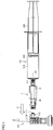
- Fig. 1 is a side view of a connector according to a first embodiment.
- a connector 1 has a second connector member 10 serving as a connector main body, and a first connector member 40 serving as a connector guide and fitting into second connector member 10.
- a tip of first connector member 40 fits into an access member 101.
- a rear end of second connector member 10 fits into a syringe 201.
- Access member 101 has a connector cap 110, and an arm portion 112 held in connector cap 110.
- a tip of arm portion 112 is a passage pawl portion 111.
- Syringe 201 has a circular cylindrical barrel 210, and a plunger 220 that fits into barrel 210.
- a tip of plunger 220 is fitted with a gasket 230.
- a tip tube 211 of barrel 210 is screwed onto second connector member 10.
- Connector 1 moves in a direction indicated by an arrow 2 and the tip of first connector member 40 thereby fits with passage pawl portion 111.
- Gasket 230 is provided to be freely slidable in barrel 210 which is a tubular container, and maintains a portion between an inner circumferential surface of barrel 210 and gasket 230 liquid-tight.
- a liquid 215 is housed in a space formed by barrel 210 and gasket 230.
- Natural rubber, butyl rubber, chlorinated butyl rubber, ethylene butadiene rubber, thermoplastic elastomer and the like can be used as gasket 230.
- the space formed by barrel 210 and gasket 230 may be empty such that a drug solution can be housed in the space in use.
- Fig. 2 is a cross-sectional view taken along line II-II in Fig. 1 .
- connector 1 has second connector member 10, first connector member 40 that fits into second connector member 10, and a housing 50 that fits into first connector member 40.
- Second connector member 10 has an inner circumferential surface 10i.
- An engaging portion 11 is provided on inner circumferential surface 10i.
- Engaging portion 11 is provided on inner circumferential surface 10i.
- a through hole 12 is provided at an end of second connector member 10.
- a hub 20 fits into through hole 12.
- Second connector member 10 may be integral with hub 20.
- a ridge 41 is provided at a rear end of first connector member 40. In a state shown in Fig. 2 , ridge 41 engages with engaging portion 11. This restricts movement of first connector member 40 in a direction away from second connector member 10.
- First connector member 40 has an inner circumferential surface 40i.
- a first pawl portion 42 is provided at the tip of first connector member 40.
- First pawl portion 42 restricts sliding of housing 50.
- Housing 50 protects a tip 31 of a needle 30.
- Tip 31 is located in a space 52 which is a through hole of housing 50.
- a stopper 51 at a tip of housing 50 engages with first pawl portion 42. This restricts sliding of housing 50 in a direction approaching second connector member 10.
- 50 has a space 53 and a space 54.
- a second sealing member 61 which is a rubber stopper is housed in space 53.
- a first sealing member 62 which is a rubber stopper is housed in space 54.
- Access member 101 has arm portion 112. The tip of arm portion 112 is passage pawl portion 111. Access member 101 holds a third sealing member 120 which is a rubber stopper. Third sealing member 120 is positioned by connector cap 110.
- Hub 20 fits into through hole 12.
- a male screw 25 is provided at a syringe-side end (female luer lock) of hub 20.
- Male screw 25 is screwed into a female screw 213 of tip tube (male luer lock) 211 of barrel 210.
- a component other than syringe 201 may be used as long as connection with hub 20 is possible.
- First sealing member 62 and second sealing member 61 may be made of, for example, a rubber member or a thermoplastic elastomer resin.
- a rubber member represented by isoprene rubber, butyl rubber, silicone rubber and the like can be used.
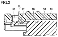
- Fig. 3 is an enlarged cross-sectional view showing a portion enclosed with III in Fig. 2 .
- first pawl portion 42 and stopper 51 are arranged in an abuttable manner.
- a first lock portion 1L has first pawl portion 42.
- stopper 51 does not abut against first pawl portion 42, However, stopper 51 can slide to a portion that abuts against first pawl portion 42.
- stopper 51 cannot slide in a right direction (direction approaching syringe 201 in Fig. 1 ) in Fig. 3 .
- Fig. 4 is a cross-sectional view of the connector before the connector is connected to the access member.
- a first inclined piece 43 is provided at the rear end of first connector member 40.
- a second inclined piece 13 is provided at a tip of second connector member 10.
- Second inclined piece 13 and a rear end 44 can abut against each other.
- Second connector member 10 has a second lock portion 2L.
- Fig. 5 is a perspective view of the tubular second connector member. As shown in Fig. 5 , through hole 12 is provided in the bottom of tubular second connector member 10. In order to allow through hole 12 to bend, through hole 12 is provided with radial grooves 12a. The number of grooves 12a may be larger or smaller than the number shown in Fig. 5 . Without having through hole 12, second connector member 10 may be integral with hub 20.
- Second inclined piece 13 is provided on inner circumferential surface 10i of second connector member 10 so as to be inclined toward the inner circumferential side.
- Second inclined piece 13 has flexibility (elasticity). That is, when second inclined piece 13 is pushed outward, second inclined piece 13 moves outward.
- Engaging portions 11 are provided at two locations of second connector member 10.
- Second connector member 10 has a tubular shape having a bottom and through hole 12 is provided in the bottom.
- second connector member 10 has a substantially octagonal shape.
- the shape of second connector member 10 is not limited thereto, and may be another polygonal shape, a circular shape or an elliptical shape.
- Fig. 6 is a perspective view of the tubular first connector member.
- First connector member 40 fits with inner circumferential surface 10i of second connector member 10. Since first connector member 40 fits into second connector member 10, first connector member 40 has a shape similar to that of inner circumferential surface 10i of second connector member 10.
- First pawl portion 42 is provided on inner circumferential surface 40i so as to protrude toward the inner circumferential side. First pawl portion 42 restricts sliding of housing 50.
- a rear end-side engaging piece 45 is provided on inner circumferential surface 40i. Rear end-side engaging piece 45 serves as a stopper that restricts sliding of housing 50.
- a front end-side engaging piece 49 is provided on inner circumferential surface 40i.
- Front end-side engaging piece 49 restricts sliding of housing 50 in a direction away from rear end-side engaging piece 45.
- First connector member 40 has first inclined piece 43.
- First inclined piece 43 is a tapered plate member.
- Ridge 41 is provided on an outer circumferential surface of first connector member 40. Ridge 41 is a convex member extending to be orthogonal to the sliding direction.
- Fig. 7 is a perspective view of the housing that protects the needle tip.
- housing 50 has stoppers 51 provided at the tip portion, a drum-like main body portion 55, space 52 passing through main body portion 55, and space 53 forming an end of space 52.
- Stoppers 51 extend in a horizontal direction (direction orthogonal to the sliding direction).
- a pair of stoppers 51 are arranged to be parallel to each other.
- Main body portion 55 extends from one end to the other end of housing 50.
- main body portion 55 has a circular cylindrical shape in this example, main body portion 55 may have a rectangular cylindrical shape.
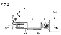
- Fig. 8 is a side view of the connector after the connector is connected to the access member. As shown in Fig. 8 , the position moves in the direction indicated by arrow 2. As a result, first connector member 40 fits with connector cap 110.
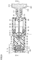
- Fig. 9 is a cross-sectional view taken along line IX-IX in Fig. 8 .
- second sealing member 61 abuts against third sealing member 120.
- Passage pawl portion 111 of arm portion 112 abuts against first pawl portion 42 and housing 50.
- passage pawl portion 111 pushes housing 50 toward the syringe 201 side, housing 50 tries to move toward the side approaching syringe 201.
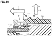
- Fig. 10 is a cross-sectional view of a portion enclosed with X in Fig. 9 .
- passage pawl portion 111 abuts against first pawl portion 42, and thus, first pawl portion 42 moves upward.
- the position of first pawl portion 42 shown in Fig. 10 moves upward (in a direction indicated by an arrow 3) relative to the position of first pawl portion 42 shown in Fig. 3 .
- Fig. 11 is a cross-sectional view taken along line XI-XI in Fig. 9 .
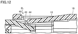
- Fig. 12 is an enlarged cross-sectional view showing a portion enclosed with XII in Fig. 11 .
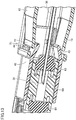
- Fig. 13 is a perspective view of the second lock portion that locks sliding of the first connector member.
- first connector member 40 cannot move from a position shown in Figs. 11 and 12 to a position approaching second connector member 10. Although the force is applied to syringe 201 such that syringe 201 approaches the access member 101 side, first connector member 40 cannot slide and move toward the second connector member 10 side because second lock portion 2L is present.
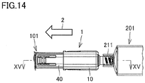
- Fig. 14 is a side view of the connector in a state where locking by the second lock portion is released.
- Fig. 15 is a cross-sectional view taken along line XV-XV in Fig. 14 .
- connector 1 is further moved in the direction approaching access member 101 from the position shown in Fig. 11 .
- first connector member 40 is deeply inserted into access member 101.
- Stopper 51 abuts against first pawl portion 42, and then, passes first pawl portion 42 and moves in the direction approaching second connector member 10.
- housing 50 moves in the direction approaching second connector member 10.
- a position of tip 31 in space 52 moves and tip 31 approaches second sealing member 61.
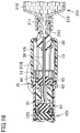
- Fig. 16 is a cross-sectional view taken along line XVI-XVI in Fig. 15 .
- Fig. 17 is a cross-sectional view of a portion enclosed with XVII in Fig. 16 .
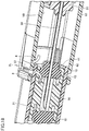
- Fig. 18 is a perspective view of the second lock portion that does not lock sliding of the first connector member.
- housing 50 moves in the direction approaching second connector member 10.
- housing 50 abuts against first inclined piece 43 and first inclined piece 43 pivots in the direction indicated by arrow 3.
- second inclined piece 13 pivots in a direction indicated by an arrow 4.
- first inclined piece 43 and second inclined piece 13 inclined with respect to first connector member 40 and second connector member 10 are no longer inclined with respect to first connector member 40 and second connector member 10 and become parallel to each other.
- second inclined piece 13 is lifted in an outer circumferential direction indicated by an arrow 4.
- rear end 44 no longer abuts against second inclined piece 13.
- first connector member 40 can slide in the direction approaching second connector member 10.
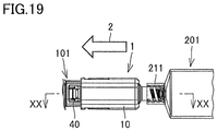
- Fig. 19 is a side view of the connector in a state where the needle communicates with the access member.
- Fig. 20 is a cross-sectional view taken along line XX-XX in Fig. 19 .
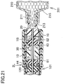
- Fig. 21 is a cross-sectional view taken along line XXI-XXI in Fig. 20 .
- first connector member 40 moves in the direction approaching syringe 201.
- first connector member 40 slides in second connector member 10.
- Housing 50 moves in the direction approaching syringe 201.
- tip 31 of needle 30 passes through second sealing member 61 and third sealing member 120 and reaches access member 101. This brings about a state in which liquid 215 can be supplied to access member 101 through needle 30.
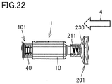
- Fig. 22 is a side view of the connector that is transferring the liquid. As shown in Fig. 22 , plunger 220 ( Fig. 1 ) is moved in the direction approaching second connector member 10. As a result, liquid 215 in Fig. 21 can be injected into access member 101.
- Fig. 23 is a side view of the connector in a state where communication with the access member is released.
- Syringe 201 is moved in a direction indicated by an arrow 5.
- connector 1 has a structure shown in Fig. 21 .
- second connector member 10 coupled to syringe 201 slides with respect to first connector member 40.
- second connector member 10 retracts to a position shown in Figs. 15 to 17 .
- Fig. 24 is a side view of the connector disconnected from the access member. As shown in Fig. 24 , when second connector member 10 is further moved in a direction indicated by an arrow 6, first connector member 40 also moves in the direction away from access member 101. As a result, as shown in Figs. 8 to 12 , first connector member 40 and second connector member 10 are positioned at the position where second lock portion 2L locks sliding of first connector member 40.
- Fig. 25 is a side view of the connector separated from the access member. As shown in Fig. 25 , when syringe 201 is moved in the direction away from access member 101, engagement between first connector member 40 and access member 101 is released. As a result, as shown in Fig. 25 , connector 1 is separated from access member 101.
- a solution in syringe 201 can be injected into a drug vial through connector 1.
- Connector 1 is connected to syringe 201 (male luer lock syringe).
- a vial access is connected to the drug vial.
- Connector 1 is brought close to the vial access and connector 1 is connected to the vial access.
- the solution in syringe 201 can be transferred to the drug vial through connector 1, the powdered drug can be dissolved in the solution, and the solution can be obtained in syringe 201.
- a liquid drug is contained in the drug vial, the drug in the drug vial can be obtained in syringe 201 through connector 1.
- a method for administering a drug solution using an infusion container in a main route and an infusion container in a sub route will be described.
- an infusion is injected into a patient using the infusion container in the main route and an infusion line.
- a bag access is connected to the infusion container in the sub route.
- the bag access is formed by access member 101, connector 1, and a tube that connects access member 101 and connector 1.
- the drug (drug solution) obtained in the above-described process is present in syringe 201.
- Connector 1 is connected to access member 101 of the bag access and the drug solution in syringe 201 is transferred from syringe 201 to the bag access.
- Connector 1 of the bag access is connected to a lock connector in the main route. As a result, the drug solution in the syringe is administered to the patient through the bag access.
- Liquid 215 is contained in syringe 201, and when liquid 215 is any liquid whose leakage to the outside is undesirable, above-described connector 1 has an excellent effect.
- connector 1 can be used for transferring liquid 215 containing pathogenic bacteria, bacteria to be prevented from having resistance, or the like.
- connector 1 can be appropriately used, for example, for transferring a drug solution from syringe 201 to a drug bag, for transferring an infusion from an infusion line to an empty syringe for sampling, for transferring a liquid specimen containing pathogenic bacteria from a specimen collecting tool to an inspection kit.
- connector 1 can be used for transferring a dangerous solvent such as trichloroethylene or liquid 215 containing an endocrine-disrupting substance.
- Connector 1 is connector 1 interposed between syringe 201 serving as a first member and access member 101 serving as a second member, connector 1 including: needle 30; housing 50 that protects tip 31 of needle 30; tubular first connector member 40 that holds housing 50 in a slidable manner; and first lock portion 1L capable of locking sliding of housing 50, housing 50 protecting tip 31 of needle 30 when sliding of housing 50 and first connector member 40 is locked, first lock portion 1L being provided on inner circumferential surface 40i of first connector member 40, first lock portion 1L engaging with access member 101 to thereby unlock housing 50, and separating from access member 101 to thereby maintain housing 50 locked.
- First lock portion 1L is provided on inner circumferential surface 40i of first connector member 40, and thus, it is difficult for an operator to touch first lock portion 1L. As a result, unlocking caused by careless operation can be prevented.
- housing 50 can be slid to expose tip 31 of needle 30. In this state, tip 31 of needle 30 is inserted into the access member, and thus, injection of the liquid using needle 30 becomes possible.
- First lock portion 1L has first pawl portion 42 that protrudes toward the inner circumferential surface 40i side of first connector member 40. Since first lock portion 1L is formed by first pawl portion 42, first lock portion 1L can be realized with a simple configuration.
- First pawl portion 42 is held by arm portion 48 having elasticity. Since arm portion 48 has elasticity, first pawl portion 42 moves easily when first pawl portion 42 engages with access member 101. As a result, access member 101 engages easily with first pawl portion 42.
- Housing 50 is provided with space 52 that houses tip 31 of needle 30 when sliding of housing 50 is locked, housing 50 has first sealing member 62 that seals space 52, and needle 30 passes through first sealing member 62. Since tip 31 of needle 30 is housed in sealed space 52, the liquid does not leak to the outside even when the liquid leaks from tip 31 of needle 30.
- Housing 50 has second sealing member 61 that seals space 52, second sealing member 61 is compression-connectable to third sealing member 120 provided in access member 101, and needle 30 passes through second sealing member 61 and third sealing member 120 in a state where second sealing member 61 and third sealing member 120 are compression-connected, and tip 31 of needle 30 thereby reaches access member 101. Since needle 30 passes through second sealing member 61 and third sealing member 120 compression-connected to each other and tip 31 reaches access member 101, exposure of tip 31 of needle 30 to the outside can be prevented. As a result, it is possible to prevent a person from coming into contact with tip 31 of needle 30.
- Connector 1 further includes: hub 20 that holds needle 30; tubular second connector member 10 that holds first connector member 40 in a slidable manner; and second lock portion 2L capable of locking sliding of first connector member 40, and through hole 12 that fits with hub 20 is provided in the bottom surface of second connector member 10. Since hub 20 fits into through hole 12, hub 20 can be reliably held by through hole 12. As a result, separation of syringe 201 from connector 1 during transfer of the liquid from syringe 201 through connector 1 to access member 101 can be reduced.
- first sealing member 62 abuts against hub 20.
- hub 20 abuts against first sealing member 62, and thus, hub 20 can be reliably positioned.
- First connector member 40 has first inclined piece 43 inclined toward the inner circumferential surface 40i side, and when housing 50 slides toward the first inclined piece 43 side, first inclined piece 43 pivots toward the outer circumferential surface side.
- Second lock portion 2L has second inclined piece 13 of second connector member 10 located outside first inclined piece 43 and inclined toward the inner circumferential surface 10i side, and when second inclined piece 13 engages with first connector member 40, sliding of first connector member 40 is locked.
- first inclined piece 43 pivots outward and abuts against second inclined piece 13 to thereby pivot second inclined piece 13 outward, engagement between second inclined piece 13 and first connector member 40 is released and first connector member 40 becomes slidable.
- first connector member 40 Since sliding of first connector member 40 is locked by first inclined piece 43 inclined toward the inner circumferential surface 40i side and second inclined piece 13 inclined toward the inner circumferential surface 10i side, it is difficult for a person to pivot first inclined piece 43 and second inclined piece 13 outward. As a result, sliding of first connector member 40 caused by person's operation can be reduced.
- Access member 101 has passage pawl portion 111 that protrudes toward the outer circumferential side, and passage pawl portion 111 moves first lock portion 1L toward the outer circumferential surface side of first connector member 40 and locking of housing 50 by first lock portion 1L can thereby be released.
- Housing 50 can be unlocked by operation of first lock portion 1L using passage pawl portion 111, and thus, locking can be released with a simple configuration.
Landscapes
- Health & Medical Sciences (AREA)
- Heart & Thoracic Surgery (AREA)
- Pulmonology (AREA)
- Engineering & Computer Science (AREA)
- Anesthesiology (AREA)
- Biomedical Technology (AREA)
- Hematology (AREA)
- Life Sciences & Earth Sciences (AREA)
- Animal Behavior & Ethology (AREA)
- General Health & Medical Sciences (AREA)
- Public Health (AREA)
- Veterinary Medicine (AREA)
- Infusion, Injection, And Reservoir Apparatuses (AREA)
Abstract
Description
- The present invention relates to a connector.
- Conventionally, connectors are described in, for example, Japanese National Patent Publication No,
2010-521219 2011-19924 -
- PTL 1: Japanese National Patent Publication No.
2010-521219 - PTL 2: Japanese Patent Laying-Open No.
2011-19924 - According to PTL 1, a first member is arranged to slide with respect to a second member between a secured position in which at least a tip of a piercing member is housed in a protection chamber and an unsecured position in which the tip of the piercing member is arranged outside the protection chamber.
- According to
PTL 2, a tip of a syringe adapter is constantly provided in a body. - In the structure described in
PTL 1, the tip of the needle can be exposed by person's operation. As a result, a person can come into contact with the tip of the needle. According toPTL 2, the tip of the needle is constantly located in the body and a biasing member is provided. Therefore, the needle cannot be connected unless the adapter is pushed in, and thus, injection of a liquid is difficult. - The present invention has been made in light of the above-described problem, and an object of the present invention is to provide a connector that makes it difficult for a person to come into contact with a tip of a needle and that facilitates injection of a liquid by connecting another member because a biasing member is not provided.
- A connector is a connector interposed between a first member and a second member, the connector including: a needle; a housing that protects a tip of the needle; a tubular first connector member that holds the housing in a slidable manner; and a first lock portion capable of locking sliding of the housing, the housing protecting the tip of the needle when sliding of the housing and the first connector member is locked, the first lock portion being provided on an inner circumferential surface of the first connector member, the first lock portion engaging with the second member to thereby unlock the housing, and separating from the second member to thereby maintain the housing locked.
- In the connector configured as described above, the first lock portion is provided on the inner circumferential surface of the first connector member, and thus, it is difficult for an operator to touch the first lock member. As a result, unlocking caused by careless operation can be prevented. Furthermore, when the first lock portion engages with the second member to thereby unlock the housing, the housing can be slid to expose the tip of the needle. In this state, the tip of the needle is inserted into the second member, and thus, injection of a liquid using the needle becomes possible.
- Preferably, the first lock portion has a first pawl portion that protrudes toward an inner circumferential surface side of the first connector member.
- Preferably, the first pawl portion is held by an arm portion having elasticity.
- Preferably, the housing is provided with a space that houses the tip of the needle when sliding of the housing is locked, the housing has a first sealing member that seals the space, and the needle passes through the first sealing member.
- Preferably, the housing has a second sealing member that seals the space, the second sealing member is compression-connectable to a third sealing member provided in the second member, and the needle passes through the second sealing member and the third sealing member in a state where the second sealing member and the third sealing member are compression-connected, and the tip of the needle thereby reaches the second member.
- Preferably, the connector further includes: a hub that holds the needle; a tubular second connector member that holds the first connector member in a slidable manner; and a second lock portion capable of locking sliding of the first connector member, and a through hole that fits with the hub is provided in a bottom surface of the second connector member. The second connector member may be integral with the hub.
- Preferably, when sliding of the housing and the first connector member is unlocked and the housing and the first connector member move in a direction approaching the hub, the first sealing member abuts against the hub.
- Preferably, the first connector member has a first inclined piece inclined toward an inner circumferential surface side, and when the housing slides toward the first inclined piece side, the first inclined piece pivots toward an outer circumferential surface side. The second lock portion has a second inclined piece of the second connector member located outside the first inclined piece and inclined toward the inner circumferential surface side, and when the second inclined piece engages with the first connector member, sliding of the first connector member is locked. When the first inclined piece pivots outward and abuts against the second inclined piece to thereby pivot the second inclined piece outward, engagement between the second inclined piece and the first connector member is released and the first connector member becomes slidable.
- Preferably, the second member has a passage pawl portion that protrudes toward an outer circumferential side, and the passage pawl portion moves the first lock portion toward an outer circumferential surface side of the first connector member and locking of the housing by the first lock portion can thereby be released.
- According to the present invention, there can be provided a connector that makes it difficult for a person to come into contact with a tip of a needle and that facilitates injection of a liquid by connecting another member.
-
-
Fig. 1 is a side view of a connector according to a first embodiment. -
Fig. 2 is a cross-sectional view taken along line II-II inFig. 1 . -
Fig. 3 is an enlarged cross-sectional view showing a portion enclosed with III inFig. 2 . -
Fig. 4 is a cross-sectional view of the connector before the connector is connected to an access member. -
Fig. 5 is a perspective view of a tubular second connector member, -
Fig. 6 is a perspective view of a tubular first connector member. -
Fig. 7 is a perspective view of a housing that protects a needle tip. -
Fig. 8 is a side view of the connector after the connector is connected to the access member. -
Fig. 9 is a cross-sectional view taken along line IX-IX inFig. 8 . -
Fig. 10 is a cross-sectional view of a portion enclosed with X inFig. 9 . -
Fig. 11 is a cross-sectional view taken along line XI-XI inFig. 9 . -
Fig. 12 is an enlarged cross-sectional view showing a portion enclosed with XII inFig. 11 . -
Fig. 13 is a perspective view of a second lock portion that locks sliding of the first connector member. -
Fig. 14 is a side view of the connector in a state where locking by the second lock portion is released. -
Fig. 15 is a cross-sectional view taken along line XV-XV inFig. 14 . -
Fig. 16 is a cross-sectional view taken along line XVI-XVI inFig. 15 , -
Fig. 17 is a cross-sectional view of a portion enclosed with XVII inFig. 16 . -
Fig. 18 is a perspective view of the second lock portion that does not lock sliding of the first connector member. -
Fig. 19 is a side view of the connector in a state where a needle communicates with the access member. -
Fig. 20 is a cross-sectional view taken along line XX-XX inFig. 19 . -
Fig. 21 is a cross-sectional view taken along line XXI-XXI inFig. 20 . -
Fig. 22 is a side view of the connector that is transferring a liquid. -
Fig. 23 is a side view of the connector in a state where communication with the access member is released. -
Fig. 24 is a side view of the connector disconnected from the access member. -
Fig. 25 is a side view of the connector separated from the access member. - An embodiment of the present invention will be described in detail hereinafter with reference to the drawings. In the embodiment described below, the same or common portions are denoted by the same reference signs in the drawings and description thereof will not be repeated.
-
Fig. 1 is a side view of a connector according to a first embodiment. As shown inFig. 1 , aconnector 1 has asecond connector member 10 serving as a connector main body, and afirst connector member 40 serving as a connector guide and fitting intosecond connector member 10. A tip offirst connector member 40 fits into anaccess member 101. A rear end ofsecond connector member 10 fits into asyringe 201. -
Access member 101 has aconnector cap 110, and anarm portion 112 held inconnector cap 110. A tip ofarm portion 112 is apassage pawl portion 111. -
Syringe 201 has a circularcylindrical barrel 210, and aplunger 220 that fits intobarrel 210. A tip ofplunger 220 is fitted with agasket 230. Atip tube 211 ofbarrel 210 is screwed ontosecond connector member 10.Connector 1 moves in a direction indicated by anarrow 2 and the tip offirst connector member 40 thereby fits withpassage pawl portion 111. -
Gasket 230 is provided to be freely slidable inbarrel 210 which is a tubular container, and maintains a portion between an inner circumferential surface ofbarrel 210 andgasket 230 liquid-tight. A liquid 215 is housed in a space formed bybarrel 210 andgasket 230. Natural rubber, butyl rubber, chlorinated butyl rubber, ethylene butadiene rubber, thermoplastic elastomer and the like can be used asgasket 230. The space formed bybarrel 210 andgasket 230 may be empty such that a drug solution can be housed in the space in use. -
Fig. 2 is a cross-sectional view taken along line II-II inFig. 1 . As shown inFig. 2 ,connector 1 hassecond connector member 10,first connector member 40 that fits intosecond connector member 10, and ahousing 50 that fits intofirst connector member 40.Second connector member 10 has an innercircumferential surface 10i. An engagingportion 11 is provided on innercircumferential surface 10i. Engagingportion 11 is provided on innercircumferential surface 10i. A throughhole 12 is provided at an end ofsecond connector member 10. Ahub 20 fits into throughhole 12.Second connector member 10 may be integral withhub 20. - A
ridge 41 is provided at a rear end offirst connector member 40. In a state shown inFig. 2 ,ridge 41 engages with engagingportion 11. This restricts movement offirst connector member 40 in a direction away fromsecond connector member 10. -
First connector member 40 has an innercircumferential surface 40i. Afirst pawl portion 42 is provided at the tip offirst connector member 40.First pawl portion 42 restricts sliding ofhousing 50.Housing 50 protects atip 31 of aneedle 30.Tip 31 is located in aspace 52 which is a through hole ofhousing 50. Astopper 51 at a tip ofhousing 50 engages withfirst pawl portion 42. This restricts sliding ofhousing 50 in a direction approachingsecond connector member 10. 50 has aspace 53 and aspace 54. Asecond sealing member 61 which is a rubber stopper is housed inspace 53. A first sealingmember 62 which is a rubber stopper is housed inspace 54. -
Access member 101 hasarm portion 112. The tip ofarm portion 112 ispassage pawl portion 111.Access member 101 holds athird sealing member 120 which is a rubber stopper. Third sealingmember 120 is positioned byconnector cap 110. -
Hub 20 fits into throughhole 12. Amale screw 25 is provided at a syringe-side end (female luer lock) ofhub 20.Male screw 25 is screwed into afemale screw 213 of tip tube (male luer lock) 211 ofbarrel 210. A component other thansyringe 201 may be used as long as connection withhub 20 is possible. - First sealing
member 62 and second sealingmember 61 may be made of, for example, a rubber member or a thermoplastic elastomer resin. When the rubber member is used, a rubber member represented by isoprene rubber, butyl rubber, silicone rubber and the like can be used. -
Fig. 3 is an enlarged cross-sectional view showing a portion enclosed with III inFig. 2 . As shown inFig. 3 ,first pawl portion 42 andstopper 51 are arranged in an abuttable manner. Afirst lock portion 1L hasfirst pawl portion 42. In a state shown inFig. 3 ,stopper 51 does not abut againstfirst pawl portion 42, However,stopper 51 can slide to a portion that abuts againstfirst pawl portion 42. Whenstopper 51 abuts againstfirst pawl portion 42,stopper 51 cannot slide in a right direction (direction approaching syringe 201 inFig. 1 ) inFig. 3 . -
Fig. 4 is a cross-sectional view of the connector before the connector is connected to the access member. As shown inFig. 4 , a firstinclined piece 43 is provided at the rear end offirst connector member 40. A secondinclined piece 13 is provided at a tip ofsecond connector member 10. Secondinclined piece 13 and arear end 44 can abut against each other.Second connector member 10 has asecond lock portion 2L. Whenfirst connector member 40 slides in the direction approachingsecond connector member 10,rear end 44 abuts against secondinclined piece 13, and sliding offirst connector member 40 is thereby restricted. -
Fig. 5 is a perspective view of the tubular second connector member. As shown inFig. 5 , throughhole 12 is provided in the bottom of tubularsecond connector member 10. In order to allow throughhole 12 to bend, throughhole 12 is provided withradial grooves 12a. The number ofgrooves 12a may be larger or smaller than the number shown inFig. 5 . Without having throughhole 12,second connector member 10 may be integral withhub 20. - Second
inclined piece 13 is provided on innercircumferential surface 10i ofsecond connector member 10 so as to be inclined toward the inner circumferential side. Secondinclined piece 13 has flexibility (elasticity). That is, when secondinclined piece 13 is pushed outward, secondinclined piece 13 moves outward. Engagingportions 11 are provided at two locations ofsecond connector member 10.Second connector member 10 has a tubular shape having a bottom and throughhole 12 is provided in the bottom. In this example,second connector member 10 has a substantially octagonal shape. However, the shape ofsecond connector member 10 is not limited thereto, and may be another polygonal shape, a circular shape or an elliptical shape. -
Fig. 6 is a perspective view of the tubular first connector member.First connector member 40 fits with innercircumferential surface 10i ofsecond connector member 10. Sincefirst connector member 40 fits intosecond connector member 10,first connector member 40 has a shape similar to that of innercircumferential surface 10i ofsecond connector member 10.First pawl portion 42 is provided on innercircumferential surface 40i so as to protrude toward the inner circumferential side.First pawl portion 42 restricts sliding ofhousing 50. A rear end-side engaging piece 45 is provided on innercircumferential surface 40i. Rear end-side engaging piece 45 serves as a stopper that restricts sliding ofhousing 50. A front end-side engaging piece 49 is provided on innercircumferential surface 40i. Front end-side engaging piece 49 restricts sliding ofhousing 50 in a direction away from rear end-side engaging piece 45.First connector member 40 has first inclinedpiece 43. Firstinclined piece 43 is a tapered plate member.Ridge 41 is provided on an outer circumferential surface offirst connector member 40.Ridge 41 is a convex member extending to be orthogonal to the sliding direction. -
Fig. 7 is a perspective view of the housing that protects the needle tip. As shown inFig. 7 ,housing 50 hasstoppers 51 provided at the tip portion, a drum-likemain body portion 55,space 52 passing throughmain body portion 55, andspace 53 forming an end ofspace 52.Stoppers 51 extend in a horizontal direction (direction orthogonal to the sliding direction). A pair ofstoppers 51 are arranged to be parallel to each other.Main body portion 55 extends from one end to the other end ofhousing 50. Althoughmain body portion 55 has a circular cylindrical shape in this example,main body portion 55 may have a rectangular cylindrical shape. -
Fig. 8 is a side view of the connector after the connector is connected to the access member. As shown inFig. 8 , the position moves in the direction indicated byarrow 2. As a result,first connector member 40 fits withconnector cap 110. -
Fig. 9 is a cross-sectional view taken along line IX-IX inFig. 8 . As shown inFig. 9 , second sealingmember 61 abuts against third sealingmember 120.Passage pawl portion 111 ofarm portion 112 abuts againstfirst pawl portion 42 andhousing 50. Whenpassage pawl portion 111 pusheshousing 50 toward thesyringe 201 side,housing 50 tries to move toward theside approaching syringe 201. -
Fig. 10 is a cross-sectional view of a portion enclosed with X inFig. 9 . As shown inFig. 10 ,passage pawl portion 111 abuts againstfirst pawl portion 42, and thus,first pawl portion 42 moves upward. Specifically, when a position offirst pawl portion 42 shown inFig. 3 is compared with a position offirst pawl portion 42 shown inFig. 10 , the position offirst pawl portion 42 shown inFig. 10 moves upward (in a direction indicated by an arrow 3) relative to the position offirst pawl portion 42 shown inFig. 3 . -
Fig. 11 is a cross-sectional view taken along line XI-XI inFig. 9 .Fig. 12 is an enlarged cross-sectional view showing a portion enclosed with XII inFig. 11 .Fig. 13 is a perspective view of the second lock portion that locks sliding of the first connector member. - As shown in
Figs. 11 to 13 , a tip of secondinclined piece 13 abuts againstrear end 44. Therefore,first connector member 40 cannot move from a position shown inFigs. 11 and12 to a position approachingsecond connector member 10. Although the force is applied tosyringe 201 such thatsyringe 201 approaches theaccess member 101 side,first connector member 40 cannot slide and move toward thesecond connector member 10 side becausesecond lock portion 2L is present. -
Fig. 14 is a side view of the connector in a state where locking by the second lock portion is released.Fig. 15 is a cross-sectional view taken along line XV-XV inFig. 14 . As shown inFigs. 14 and15 ,connector 1 is further moved in the direction approachingaccess member 101 from the position shown inFig. 11 . Then,first connector member 40 is deeply inserted intoaccess member 101.Stopper 51 abuts againstfirst pawl portion 42, and then, passesfirst pawl portion 42 and moves in the direction approachingsecond connector member 10. With this,housing 50 moves in the direction approachingsecond connector member 10. As a result, a position oftip 31 inspace 52 moves and tip 31 approaches second sealingmember 61. -
Fig. 16 is a cross-sectional view taken along line XVI-XVI inFig. 15 .Fig. 17 is a cross-sectional view of a portion enclosed with XVII inFig. 16 .Fig. 18 is a perspective view of the second lock portion that does not lock sliding of the first connector member. - As shown in
Figs. 16 to 18 ,housing 50 moves in the direction approachingsecond connector member 10. As a result,housing 50 abuts against firstinclined piece 43 and firstinclined piece 43 pivots in the direction indicated byarrow 3. Since an outer circumferential portion of firstinclined piece 43 abuts against secondinclined piece 13, secondinclined piece 13 pivots in a direction indicated by anarrow 4. As a result, firstinclined piece 43 and secondinclined piece 13 inclined with respect tofirst connector member 40 andsecond connector member 10 are no longer inclined with respect tofirst connector member 40 andsecond connector member 10 and become parallel to each other. As shown inFig. 18 , secondinclined piece 13 is lifted in an outer circumferential direction indicated by anarrow 4. Thus,rear end 44 no longer abuts against secondinclined piece 13. As a result,first connector member 40 can slide in the direction approachingsecond connector member 10. -
Fig. 19 is a side view of the connector in a state where the needle communicates with the access member.Fig. 20 is a cross-sectional view taken along line XX-XX inFig. 19 .Fig. 21 is a cross-sectional view taken along line XXI-XXI inFig. 20 . - As shown in
Figs, 19 to 21 ,first connector member 40 moves in thedirection approaching syringe 201. As a result,first connector member 40 slides insecond connector member 10.Housing 50 moves in thedirection approaching syringe 201. As a result,tip 31 ofneedle 30 passes through second sealingmember 61 and third sealingmember 120 and reachesaccess member 101. This brings about a state in which liquid 215 can be supplied to accessmember 101 throughneedle 30. -
Fig. 22 is a side view of the connector that is transferring the liquid. As shown inFig. 22 , plunger 220 (Fig. 1 ) is moved in the direction approachingsecond connector member 10. As a result, liquid 215 inFig. 21 can be injected intoaccess member 101. -
Fig. 23 is a side view of the connector in a state where communication with the access member is released. As shown inFig. 23 , when injection of the liquid ends, it is necessary to detachconnector 1 fromaccess member 101.Syringe 201 is moved in a direction indicated by anarrow 5. In a state where injection ends,connector 1 has a structure shown inFig. 21 . Whensyringe 201 is moved from this state in the direction indicated byarrow 5,second connector member 10 coupled tosyringe 201 slides with respect tofirst connector member 40. As a result,second connector member 10 retracts to a position shown inFigs. 15 to 17 . -
Fig. 24 is a side view of the connector disconnected from the access member. As shown inFig. 24 , whensecond connector member 10 is further moved in a direction indicated by anarrow 6,first connector member 40 also moves in the direction away fromaccess member 101. As a result, as shown inFigs. 8 to 12 ,first connector member 40 andsecond connector member 10 are positioned at the position wheresecond lock portion 2L locks sliding offirst connector member 40. -
Fig. 25 is a side view of the connector separated from the access member. As shown inFig. 25 , whensyringe 201 is moved in the direction away fromaccess member 101, engagement betweenfirst connector member 40 andaccess member 101 is released. As a result, as shown inFig. 25 ,connector 1 is separated fromaccess member 101. - Using the connector shown in
Fig. 4 , a solution insyringe 201 can be injected into a drug vial throughconnector 1. - When the drug solution is obtained from the drug
vial using connector 1, the following procedure is followed. -
Connector 1 is connected to syringe 201 (male luer lock syringe). A vial access is connected to the drug vial.Connector 1 is brought close to the vial access andconnector 1 is connected to the vial access. When a powdered drug is contained in the drug vial, the solution insyringe 201 can be transferred to the drug vial throughconnector 1, the powdered drug can be dissolved in the solution, and the solution can be obtained insyringe 201. When a liquid drug is contained in the drug vial, the drug in the drug vial can be obtained insyringe 201 throughconnector 1. - A method for administering a drug solution using an infusion container in a main route and an infusion container in a sub route will be described. First, an infusion is injected into a patient using the infusion container in the main route and an infusion line. A bag access is connected to the infusion container in the sub route. The bag access is formed by
access member 101,connector 1, and a tube that connectsaccess member 101 andconnector 1. The drug (drug solution) obtained in the above-described process is present insyringe 201.Connector 1 is connected to accessmember 101 of the bag access and the drug solution insyringe 201 is transferred fromsyringe 201 to the bag access.Connector 1 of the bag access is connected to a lock connector in the main route. As a result, the drug solution in the syringe is administered to the patient through the bag access. -
Liquid 215 is contained insyringe 201, and when liquid 215 is any liquid whose leakage to the outside is undesirable, above-describedconnector 1 has an excellent effect. For example, in addition to dangerous drug such as anti-cancer drug,connector 1 can be used for transferring liquid 215 containing pathogenic bacteria, bacteria to be prevented from having resistance, or the like. Specifically,connector 1 can be appropriately used, for example, for transferring a drug solution fromsyringe 201 to a drug bag, for transferring an infusion from an infusion line to an empty syringe for sampling, for transferring a liquid specimen containing pathogenic bacteria from a specimen collecting tool to an inspection kit. Also,connector 1 can be used for transferring a dangerous solvent such as trichloroethylene or liquid 215 containing an endocrine-disrupting substance. - Even when
such liquid 215 adheres to tip 31 ofneedle 30, greater safety is secured becausetip 31 ofneedle 30 is not exposed. -
Connector 1 isconnector 1 interposed betweensyringe 201 serving as a first member andaccess member 101 serving as a second member,connector 1 including:needle 30;housing 50 that protectstip 31 ofneedle 30; tubularfirst connector member 40 that holdshousing 50 in a slidable manner; andfirst lock portion 1L capable of locking sliding ofhousing 50,housing 50 protectingtip 31 ofneedle 30 when sliding ofhousing 50 andfirst connector member 40 is locked,first lock portion 1L being provided on innercircumferential surface 40i offirst connector member 40,first lock portion 1L engaging withaccess member 101 to thereby unlockhousing 50, and separating fromaccess member 101 to thereby maintainhousing 50 locked.First lock portion 1L is provided on innercircumferential surface 40i offirst connector member 40, and thus, it is difficult for an operator to touchfirst lock portion 1L. As a result, unlocking caused by careless operation can be prevented. - Furthermore, when
first lock portion 1L engages withaccess member 101 to thereby unlockhousing 50,housing 50 can be slid to exposetip 31 ofneedle 30. In this state, tip 31 ofneedle 30 is inserted into the access member, and thus, injection of theliquid using needle 30 becomes possible. -
First lock portion 1L hasfirst pawl portion 42 that protrudes toward the innercircumferential surface 40i side offirst connector member 40. Sincefirst lock portion 1L is formed byfirst pawl portion 42,first lock portion 1L can be realized with a simple configuration. -
First pawl portion 42 is held byarm portion 48 having elasticity. Sincearm portion 48 has elasticity,first pawl portion 42 moves easily whenfirst pawl portion 42 engages withaccess member 101. As a result,access member 101 engages easily withfirst pawl portion 42. -
Housing 50 is provided withspace 52 that houses tip 31 ofneedle 30 when sliding ofhousing 50 is locked,housing 50 has first sealingmember 62 that sealsspace 52, and needle 30 passes through first sealingmember 62. Sincetip 31 ofneedle 30 is housed in sealedspace 52, the liquid does not leak to the outside even when the liquid leaks fromtip 31 ofneedle 30. -
Housing 50 has second sealingmember 61 that sealsspace 52, second sealingmember 61 is compression-connectable tothird sealing member 120 provided inaccess member 101, and needle 30 passes through second sealingmember 61 and third sealingmember 120 in a state where second sealingmember 61 and third sealingmember 120 are compression-connected, andtip 31 ofneedle 30 thereby reachesaccess member 101. Sinceneedle 30 passes through second sealingmember 61 and third sealingmember 120 compression-connected to each other andtip 31reaches access member 101, exposure oftip 31 ofneedle 30 to the outside can be prevented. As a result, it is possible to prevent a person from coming into contact withtip 31 ofneedle 30. -
Connector 1 further includes:hub 20 that holdsneedle 30; tubularsecond connector member 10 that holdsfirst connector member 40 in a slidable manner; andsecond lock portion 2L capable of locking sliding offirst connector member 40, and throughhole 12 that fits withhub 20 is provided in the bottom surface ofsecond connector member 10. Sincehub 20 fits into throughhole 12,hub 20 can be reliably held by throughhole 12. As a result, separation ofsyringe 201 fromconnector 1 during transfer of the liquid fromsyringe 201 throughconnector 1 to accessmember 101 can be reduced. - When sliding of
housing 50 andfirst connector member 40 is unlocked andhousing 50 andfirst connector member 40 move in adirection approaching hub 20, first sealingmember 62 abuts againsthub 20. In this case,hub 20 abuts against first sealingmember 62, and thus,hub 20 can be reliably positioned. -
First connector member 40 has first inclinedpiece 43 inclined toward the innercircumferential surface 40i side, and whenhousing 50 slides toward the firstinclined piece 43 side, firstinclined piece 43 pivots toward the outer circumferential surface side.Second lock portion 2L has second inclinedpiece 13 ofsecond connector member 10 located outside firstinclined piece 43 and inclined toward the innercircumferential surface 10i side, and when secondinclined piece 13 engages withfirst connector member 40, sliding offirst connector member 40 is locked. When first inclinedpiece 43 pivots outward and abuts against secondinclined piece 13 to thereby pivot secondinclined piece 13 outward, engagement between secondinclined piece 13 andfirst connector member 40 is released andfirst connector member 40 becomes slidable. Since sliding offirst connector member 40 is locked by firstinclined piece 43 inclined toward the innercircumferential surface 40i side and secondinclined piece 13 inclined toward the innercircumferential surface 10i side, it is difficult for a person to pivot firstinclined piece 43 and secondinclined piece 13 outward. As a result, sliding offirst connector member 40 caused by person's operation can be reduced. -
Access member 101 haspassage pawl portion 111 that protrudes toward the outer circumferential side, andpassage pawl portion 111 movesfirst lock portion 1L toward the outer circumferential surface side offirst connector member 40 and locking ofhousing 50 byfirst lock portion 1L can thereby be released.Housing 50 can be unlocked by operation offirst lock portion 1L usingpassage pawl portion 111, and thus, locking can be released with a simple configuration. - While the embodiment of the present invention has been described above, the embodiment disclosed herein is illustrative and non-restrictive in every respect. The scope of the present invention is defined by the terms of the claims and is intended to include any modifications within the scope and meaning equivalent to the terms of the claims.
- 1 connector; 1L first lock portion; 2L second lock portion; 10 second connector member; 10i, 40i inner circumferential surface; 11 engaging portion; 12 through hole; 12a groove; 13 second inclined piece; 20 hub; 25 male screw; 30 needle; 31 tip; 40 first connector member; 41 ridge; 42 first pawl portion; 43 first inclined piece; 44 rear end; 45 rear end-side engaging piece; 48, 112 arm portion; 49 front end-side engaging piece; 50 housing; 51 stopper; 52, 53, 54 space; 55 main body portion; 61 second sealing member; 62 first sealing member; 101 access member; 110 connector cap; 111 passage pawl portion; 120 third sealing member; 201 syringe; 210 barrel; 211 tip tube; 213 female screw; 215 liquid; 220 plunger; 230 gasket.
Claims (9)
- A connector interposed between a first member and a second member, the connector comprising:a needle;a housing that protects a tip of the needle;a tubular first connector member that holds the housing in a slidable manner; anda first lock portion capable of locking sliding of the housing,the housing protecting the tip of the needle when sliding of the housing and the first connector member is locked,the first lock portion being provided on an inner circumferential surface of the first connector member,the first lock portion engaging with the second member to thereby unlock the housing, and separating from the second member to thereby maintain the housing locked.
- The connector according to claim 1, wherein
the first lock portion has a first pawl portion that protrudes toward an inner circumferential surface side of the first connector member. - The connector according to claim 2, wherein
the first pawl portion is held by an arm portion having elasticity. - The connector according to any one of claims 1 to 3, wherein
the housing is provided with a space that houses the tip of the needle when sliding of the housing is locked,
the housing has a first sealing member that seals the space, and
the needle passes through the first sealing member. - The connector according to claim 4, wherein
the housing has a second sealing member that seals the space, the second sealing member is compression-connectable to a third sealing member provided in the second member, and
the needle passes through the second sealing member and the third sealing member in a state where the second sealing member and the third sealing member are compression-connected, and the tip of the needle thereby reaches the second member. - The connector according to claim 4 or 5, further comprising:a hub that holds the needle;a tubular second connector member that holds the first connector member in a slidable manner; anda second lock portion capable of locking sliding of the first connector member, whereina through hole that fits with the hub is provided in a bottom surface of the second connector member.
- The connector according to claim 6, wherein
when sliding of the housing and the first connector member is unlocked and the housing and the first connector member move in a direction approaching the hub, the first sealing member abuts against the hub. - The connector according to claim 6 or 7, wherein
the first connector member has a first inclined piece inclined toward an inner circumferential surface side, and when the housing slides toward the first inclined piece side, the first inclined piece pivots toward an outer circumferential surface side,
the second lock portion has a second inclined piece of the second connector member located outside the first inclined piece and inclined toward the inner circumferential surface side, and when the second inclined piece engages with the first connector member, sliding of the first connector member is locked, and
when the first inclined piece pivots outward and abuts against the second inclined piece to thereby pivot the second inclined piece outward, engagement between the second inclined piece and the first connector member is released and the first connector member becomes slidable. - The connector according to any one of claims 1 to 8, wherein
the second member has a passage pawl portion that protrudes toward an outer circumferential side, and
the passage pawl portion moves the first lock portion toward an outer circumferential surface side of the first connector member and locking of the housing by the first lock portion can thereby be released.
Applications Claiming Priority (2)
| Application Number | Priority Date | Filing Date | Title |
|---|---|---|---|
| JP2017074542 | 2017-04-04 | ||
| PCT/JP2018/013200 WO2018186276A1 (en) | 2017-04-04 | 2018-03-29 | Connector |
Publications (3)
| Publication Number | Publication Date |
|---|---|
| EP3607993A1 true EP3607993A1 (en) | 2020-02-12 |
| EP3607993A4 EP3607993A4 (en) | 2021-01-06 |
| EP3607993B1 EP3607993B1 (en) | 2024-07-10 |
Family
ID=63713121
Family Applications (1)
| Application Number | Title | Priority Date | Filing Date |
|---|---|---|---|
| EP18781431.4A Active EP3607993B1 (en) | 2017-04-04 | 2018-03-29 | Connector |
Country Status (5)
| Country | Link |
|---|---|
| EP (1) | EP3607993B1 (en) |
| JP (1) | JP7172993B2 (en) |
| AU (1) | AU2018249974B2 (en) |
| ES (1) | ES2987636T3 (en) |
| WO (1) | WO2018186276A1 (en) |
Cited By (4)
| Publication number | Priority date | Publication date | Assignee | Title |
|---|---|---|---|---|
| US11951273B2 (en) | 2020-03-06 | 2024-04-09 | B. Braun Melsungen Ag | Coupling system for a closed fluid transfer system |
| US12048827B2 (en) | 2020-03-06 | 2024-07-30 | B. Braun Melsungen Ag | Coupling element for a closed fluid transfer system, counter coupling element for a coupling element of this type, and coupling system |
| US12303661B2 (en) | 2020-03-06 | 2025-05-20 | B. Braun Melsungen Ag | Coupling element and coupling system for a closed fluid transfer system |
| WO2026067768A1 (en) * | 2024-09-30 | 2026-04-02 | 天津九安医疗电子股份有限公司 | Emitter assembly and detection assembly |
Family Cites Families (8)
| Publication number | Priority date | Publication date | Assignee | Title |
|---|---|---|---|---|
| US7425209B2 (en) * | 1998-09-15 | 2008-09-16 | Baxter International Inc. | Sliding reconstitution device for a diluent container |
| US6715520B2 (en) * | 2001-10-11 | 2004-04-06 | Carmel Pharma Ab | Method and assembly for fluid transfer |
| PT2463201E (en) | 2003-10-30 | 2014-05-09 | Teva Medical Ltd | Safety drug handling device |
| ES2613073T3 (en) | 2007-03-16 | 2017-05-22 | Carmel Pharma Ab | A drilling element protection device |
| EP2606872B1 (en) * | 2007-04-23 | 2014-07-02 | Equashield Medical Ltd | Method and apparatus for contamination-free transfer of a hazardous drug |
| IL221635A0 (en) * | 2012-08-26 | 2012-12-31 | Medimop Medical Projects Ltd | Drug vial mixing and transfer device for use with iv bag and drug vial |
| US9414991B2 (en) * | 2013-11-06 | 2016-08-16 | Becton Dickinson and Company Limited | Medical connector having locking engagement |
| CN110448461B (en) * | 2014-04-21 | 2022-07-01 | 贝克顿迪金森有限公司 | Syringe adapter with disconnect feedback mechanism |
-
2018
- 2018-03-29 WO PCT/JP2018/013200 patent/WO2018186276A1/en not_active Ceased
- 2018-03-29 JP JP2019511193A patent/JP7172993B2/en active Active
- 2018-03-29 EP EP18781431.4A patent/EP3607993B1/en active Active
- 2018-03-29 ES ES18781431T patent/ES2987636T3/en active Active
- 2018-03-29 AU AU2018249974A patent/AU2018249974B2/en active Active
Cited By (4)
| Publication number | Priority date | Publication date | Assignee | Title |
|---|---|---|---|---|
| US11951273B2 (en) | 2020-03-06 | 2024-04-09 | B. Braun Melsungen Ag | Coupling system for a closed fluid transfer system |
| US12048827B2 (en) | 2020-03-06 | 2024-07-30 | B. Braun Melsungen Ag | Coupling element for a closed fluid transfer system, counter coupling element for a coupling element of this type, and coupling system |
| US12303661B2 (en) | 2020-03-06 | 2025-05-20 | B. Braun Melsungen Ag | Coupling element and coupling system for a closed fluid transfer system |
| WO2026067768A1 (en) * | 2024-09-30 | 2026-04-02 | 天津九安医疗电子股份有限公司 | Emitter assembly and detection assembly |
Also Published As
| Publication number | Publication date |
|---|---|
| EP3607993B1 (en) | 2024-07-10 |
| ES2987636T3 (en) | 2024-11-15 |
| JPWO2018186276A1 (en) | 2020-02-13 |
| WO2018186276A1 (en) | 2018-10-11 |
| AU2018249974A1 (en) | 2019-11-21 |
| EP3607993A4 (en) | 2021-01-06 |
| AU2018249974B2 (en) | 2023-06-15 |
| JP7172993B2 (en) | 2022-11-16 |
Similar Documents
| Publication | Publication Date | Title |
|---|---|---|
| AU2023204298B2 (en) | Connector for system for closed transfer of fluids | |
| CN105792793B (en) | Liquid-tight transfer system with connector | |
| US10850087B2 (en) | Fluid transfer device and packaging therefor | |
| AU2018210218B2 (en) | Syringe adapter for closed transfer of fluids | |
| AU2018210219B2 (en) | Syringe adapter with lock mechanism | |
| US12383466B2 (en) | Fluid transfer device and packaging therefor | |
| CN110448461B (en) | Syringe adapter with disconnect feedback mechanism | |
| AU2018249974B2 (en) | Connector | |
| JP2024529125A (en) | Syringe adapter with needle hub |
Legal Events
| Date | Code | Title | Description |
|---|---|---|---|
| STAA | Information on the status of an ep patent application or granted ep patent |
Free format text: STATUS: THE INTERNATIONAL PUBLICATION HAS BEEN MADE |
|
| PUAI | Public reference made under article 153(3) epc to a published international application that has entered the european phase |
Free format text: ORIGINAL CODE: 0009012 |
|
| STAA | Information on the status of an ep patent application or granted ep patent |
Free format text: STATUS: REQUEST FOR EXAMINATION WAS MADE |
|
| 17P | Request for examination filed |
Effective date: 20191030 |
|
| AK | Designated contracting states |
Kind code of ref document: A1 Designated state(s): AL AT BE BG CH CY CZ DE DK EE ES FI FR GB GR HR HU IE IS IT LI LT LU LV MC MK MT NL NO PL PT RO RS SE SI SK SM TR |
|
| AX | Request for extension of the european patent |
Extension state: BA ME |
|
| DAV | Request for validation of the european patent (deleted) | ||
| DAX | Request for extension of the european patent (deleted) | ||
| A4 | Supplementary search report drawn up and despatched |
Effective date: 20201208 |
|
| RIC1 | Information provided on ipc code assigned before grant |
Ipc: A61J 1/20 20060101ALI20201202BHEP Ipc: A61M 39/10 20060101AFI20201202BHEP |
|
| STAA | Information on the status of an ep patent application or granted ep patent |
Free format text: STATUS: EXAMINATION IS IN PROGRESS |
|
| 17Q | First examination report despatched |
Effective date: 20211119 |
|
| GRAP | Despatch of communication of intention to grant a patent |
Free format text: ORIGINAL CODE: EPIDOSNIGR1 |
|
| STAA | Information on the status of an ep patent application or granted ep patent |
Free format text: STATUS: GRANT OF PATENT IS INTENDED |
|
| INTG | Intention to grant announced |
Effective date: 20240209 |
|
| GRAS | Grant fee paid |
Free format text: ORIGINAL CODE: EPIDOSNIGR3 |
|
| GRAA | (expected) grant |
Free format text: ORIGINAL CODE: 0009210 |
|
| STAA | Information on the status of an ep patent application or granted ep patent |
Free format text: STATUS: THE PATENT HAS BEEN GRANTED |
|
| RAP3 | Party data changed (applicant data changed or rights of an application transferred) |
Owner name: NIPRO CORPORATION |
|
| AK | Designated contracting states |
Kind code of ref document: B1 Designated state(s): AL AT BE BG CH CY CZ DE DK EE ES FI FR GB GR HR HU IE IS IT LI LT LU LV MC MK MT NL NO PL PT RO RS SE SI SK SM TR |
|
| REG | Reference to a national code |
Ref country code: CH Ref legal event code: EP |
|
| P01 | Opt-out of the competence of the unified patent court (upc) registered |
Free format text: CASE NUMBER: APP_34025/2024 Effective date: 20240606 |
|
| REG | Reference to a national code |
Ref country code: DE Ref legal event code: R096 Ref document number: 602018071603 Country of ref document: DE |
|
| REG | Reference to a national code |
Ref country code: LT Ref legal event code: MG9D |
|
| REG | Reference to a national code |
Ref country code: NL Ref legal event code: MP Effective date: 20240710 |
|
| REG | Reference to a national code |
Ref country code: ES Ref legal event code: FG2A Ref document number: 2987636 Country of ref document: ES Kind code of ref document: T3 Effective date: 20241115 |
|
| PG25 | Lapsed in a contracting state [announced via postgrant information from national office to epo] |
Ref country code: PT Free format text: LAPSE BECAUSE OF FAILURE TO SUBMIT A TRANSLATION OF THE DESCRIPTION OR TO PAY THE FEE WITHIN THE PRESCRIBED TIME-LIMIT Effective date: 20241111 |
|
| REG | Reference to a national code |
Ref country code: AT Ref legal event code: MK05 Ref document number: 1701520 Country of ref document: AT Kind code of ref document: T Effective date: 20240710 |
|
| PG25 | Lapsed in a contracting state [announced via postgrant information from national office to epo] |
Ref country code: NL Free format text: LAPSE BECAUSE OF FAILURE TO SUBMIT A TRANSLATION OF THE DESCRIPTION OR TO PAY THE FEE WITHIN THE PRESCRIBED TIME-LIMIT Effective date: 20240710 |
|
| PG25 | Lapsed in a contracting state [announced via postgrant information from national office to epo] |
Ref country code: PT Free format text: LAPSE BECAUSE OF FAILURE TO SUBMIT A TRANSLATION OF THE DESCRIPTION OR TO PAY THE FEE WITHIN THE PRESCRIBED TIME-LIMIT Effective date: 20241111 Ref country code: NL Free format text: LAPSE BECAUSE OF FAILURE TO SUBMIT A TRANSLATION OF THE DESCRIPTION OR TO PAY THE FEE WITHIN THE PRESCRIBED TIME-LIMIT Effective date: 20240710 |
|
| PG25 | Lapsed in a contracting state [announced via postgrant information from national office to epo] |
Ref country code: NO Free format text: LAPSE BECAUSE OF FAILURE TO SUBMIT A TRANSLATION OF THE DESCRIPTION OR TO PAY THE FEE WITHIN THE PRESCRIBED TIME-LIMIT Effective date: 20241010 |
|
| PG25 | Lapsed in a contracting state [announced via postgrant information from national office to epo] |
Ref country code: GR Free format text: LAPSE BECAUSE OF FAILURE TO SUBMIT A TRANSLATION OF THE DESCRIPTION OR TO PAY THE FEE WITHIN THE PRESCRIBED TIME-LIMIT Effective date: 20241011 Ref country code: FI Free format text: LAPSE BECAUSE OF FAILURE TO SUBMIT A TRANSLATION OF THE DESCRIPTION OR TO PAY THE FEE WITHIN THE PRESCRIBED TIME-LIMIT Effective date: 20240710 Ref country code: PL Free format text: LAPSE BECAUSE OF FAILURE TO SUBMIT A TRANSLATION OF THE DESCRIPTION OR TO PAY THE FEE WITHIN THE PRESCRIBED TIME-LIMIT Effective date: 20240710 |
|
| PG25 | Lapsed in a contracting state [announced via postgrant information from national office to epo] |
Ref country code: BG Free format text: LAPSE BECAUSE OF FAILURE TO SUBMIT A TRANSLATION OF THE DESCRIPTION OR TO PAY THE FEE WITHIN THE PRESCRIBED TIME-LIMIT Effective date: 20240710 |
|
| PG25 | Lapsed in a contracting state [announced via postgrant information from national office to epo] |
Ref country code: LV Free format text: LAPSE BECAUSE OF FAILURE TO SUBMIT A TRANSLATION OF THE DESCRIPTION OR TO PAY THE FEE WITHIN THE PRESCRIBED TIME-LIMIT Effective date: 20240710 |
|
| PG25 | Lapsed in a contracting state [announced via postgrant information from national office to epo] |
Ref country code: IS Free format text: LAPSE BECAUSE OF FAILURE TO SUBMIT A TRANSLATION OF THE DESCRIPTION OR TO PAY THE FEE WITHIN THE PRESCRIBED TIME-LIMIT Effective date: 20241110 Ref country code: AT Free format text: LAPSE BECAUSE OF FAILURE TO SUBMIT A TRANSLATION OF THE DESCRIPTION OR TO PAY THE FEE WITHIN THE PRESCRIBED TIME-LIMIT Effective date: 20240710 |
|
| PG25 | Lapsed in a contracting state [announced via postgrant information from national office to epo] |
Ref country code: HR Free format text: LAPSE BECAUSE OF FAILURE TO SUBMIT A TRANSLATION OF THE DESCRIPTION OR TO PAY THE FEE WITHIN THE PRESCRIBED TIME-LIMIT Effective date: 20240710 |
|
| PG25 | Lapsed in a contracting state [announced via postgrant information from national office to epo] |
Ref country code: RS Free format text: LAPSE BECAUSE OF FAILURE TO SUBMIT A TRANSLATION OF THE DESCRIPTION OR TO PAY THE FEE WITHIN THE PRESCRIBED TIME-LIMIT Effective date: 20241010 |
|
| PG25 | Lapsed in a contracting state [announced via postgrant information from national office to epo] |
Ref country code: RS Free format text: LAPSE BECAUSE OF FAILURE TO SUBMIT A TRANSLATION OF THE DESCRIPTION OR TO PAY THE FEE WITHIN THE PRESCRIBED TIME-LIMIT Effective date: 20241010 Ref country code: PL Free format text: LAPSE BECAUSE OF FAILURE TO SUBMIT A TRANSLATION OF THE DESCRIPTION OR TO PAY THE FEE WITHIN THE PRESCRIBED TIME-LIMIT Effective date: 20240710 Ref country code: NO Free format text: LAPSE BECAUSE OF FAILURE TO SUBMIT A TRANSLATION OF THE DESCRIPTION OR TO PAY THE FEE WITHIN THE PRESCRIBED TIME-LIMIT Effective date: 20241010 Ref country code: LV Free format text: LAPSE BECAUSE OF FAILURE TO SUBMIT A TRANSLATION OF THE DESCRIPTION OR TO PAY THE FEE WITHIN THE PRESCRIBED TIME-LIMIT Effective date: 20240710 Ref country code: IS Free format text: LAPSE BECAUSE OF FAILURE TO SUBMIT A TRANSLATION OF THE DESCRIPTION OR TO PAY THE FEE WITHIN THE PRESCRIBED TIME-LIMIT Effective date: 20241110 Ref country code: HR Free format text: LAPSE BECAUSE OF FAILURE TO SUBMIT A TRANSLATION OF THE DESCRIPTION OR TO PAY THE FEE WITHIN THE PRESCRIBED TIME-LIMIT Effective date: 20240710 Ref country code: GR Free format text: LAPSE BECAUSE OF FAILURE TO SUBMIT A TRANSLATION OF THE DESCRIPTION OR TO PAY THE FEE WITHIN THE PRESCRIBED TIME-LIMIT Effective date: 20241011 Ref country code: FI Free format text: LAPSE BECAUSE OF FAILURE TO SUBMIT A TRANSLATION OF THE DESCRIPTION OR TO PAY THE FEE WITHIN THE PRESCRIBED TIME-LIMIT Effective date: 20240710 Ref country code: BG Free format text: LAPSE BECAUSE OF FAILURE TO SUBMIT A TRANSLATION OF THE DESCRIPTION OR TO PAY THE FEE WITHIN THE PRESCRIBED TIME-LIMIT Effective date: 20240710 Ref country code: AT Free format text: LAPSE BECAUSE OF FAILURE TO SUBMIT A TRANSLATION OF THE DESCRIPTION OR TO PAY THE FEE WITHIN THE PRESCRIBED TIME-LIMIT Effective date: 20240710 |
|
| REG | Reference to a national code |
Ref country code: DE Ref legal event code: R097 Ref document number: 602018071603 Country of ref document: DE |
|
| PG25 | Lapsed in a contracting state [announced via postgrant information from national office to epo] |
Ref country code: DK Free format text: LAPSE BECAUSE OF FAILURE TO SUBMIT A TRANSLATION OF THE DESCRIPTION OR TO PAY THE FEE WITHIN THE PRESCRIBED TIME-LIMIT Effective date: 20240710 Ref country code: RO Free format text: LAPSE BECAUSE OF FAILURE TO SUBMIT A TRANSLATION OF THE DESCRIPTION OR TO PAY THE FEE WITHIN THE PRESCRIBED TIME-LIMIT Effective date: 20240710 Ref country code: SM Free format text: LAPSE BECAUSE OF FAILURE TO SUBMIT A TRANSLATION OF THE DESCRIPTION OR TO PAY THE FEE WITHIN THE PRESCRIBED TIME-LIMIT Effective date: 20240710 |
|
| PG25 | Lapsed in a contracting state [announced via postgrant information from national office to epo] |
Ref country code: EE Free format text: LAPSE BECAUSE OF FAILURE TO SUBMIT A TRANSLATION OF THE DESCRIPTION OR TO PAY THE FEE WITHIN THE PRESCRIBED TIME-LIMIT Effective date: 20240710 |
|
| PG25 | Lapsed in a contracting state [announced via postgrant information from national office to epo] |
Ref country code: CZ Free format text: LAPSE BECAUSE OF FAILURE TO SUBMIT A TRANSLATION OF THE DESCRIPTION OR TO PAY THE FEE WITHIN THE PRESCRIBED TIME-LIMIT Effective date: 20240710 |
|
| PG25 | Lapsed in a contracting state [announced via postgrant information from national office to epo] |
Ref country code: IT Free format text: LAPSE BECAUSE OF FAILURE TO SUBMIT A TRANSLATION OF THE DESCRIPTION OR TO PAY THE FEE WITHIN THE PRESCRIBED TIME-LIMIT Effective date: 20240710 Ref country code: SK Free format text: LAPSE BECAUSE OF FAILURE TO SUBMIT A TRANSLATION OF THE DESCRIPTION OR TO PAY THE FEE WITHIN THE PRESCRIBED TIME-LIMIT Effective date: 20240710 |
|
| PLBE | No opposition filed within time limit |
Free format text: ORIGINAL CODE: 0009261 |
|
| STAA | Information on the status of an ep patent application or granted ep patent |
Free format text: STATUS: NO OPPOSITION FILED WITHIN TIME LIMIT |
|
| 26N | No opposition filed |
Effective date: 20250411 |
|
| PGFP | Annual fee paid to national office [announced via postgrant information from national office to epo] |
Ref country code: ES Payment date: 20250429 Year of fee payment: 8 |
|
| PG25 | Lapsed in a contracting state [announced via postgrant information from national office to epo] |
Ref country code: SE Free format text: LAPSE BECAUSE OF FAILURE TO SUBMIT A TRANSLATION OF THE DESCRIPTION OR TO PAY THE FEE WITHIN THE PRESCRIBED TIME-LIMIT Effective date: 20240710 |
|
| PG25 | Lapsed in a contracting state [announced via postgrant information from national office to epo] |
Ref country code: MC Free format text: LAPSE BECAUSE OF FAILURE TO SUBMIT A TRANSLATION OF THE DESCRIPTION OR TO PAY THE FEE WITHIN THE PRESCRIBED TIME-LIMIT Effective date: 20240710 |
|
| REG | Reference to a national code |
Ref country code: CH Ref legal event code: H13 Free format text: ST27 STATUS EVENT CODE: U-0-0-H10-H13 (AS PROVIDED BY THE NATIONAL OFFICE) Effective date: 20251024 |
|
| PG25 | Lapsed in a contracting state [announced via postgrant information from national office to epo] |
Ref country code: LU Free format text: LAPSE BECAUSE OF NON-PAYMENT OF DUE FEES Effective date: 20250329 |
|
| REG | Reference to a national code |
Ref country code: BE Ref legal event code: MM Effective date: 20250331 |
|
| PG25 | Lapsed in a contracting state [announced via postgrant information from national office to epo] |
Ref country code: FR Free format text: LAPSE BECAUSE OF NON-PAYMENT OF DUE FEES Effective date: 20250331 |
|
| PG25 | Lapsed in a contracting state [announced via postgrant information from national office to epo] |
Ref country code: BE Free format text: LAPSE BECAUSE OF NON-PAYMENT OF DUE FEES Effective date: 20250331 |
|
| PG25 | Lapsed in a contracting state [announced via postgrant information from national office to epo] |
Ref country code: CH Free format text: LAPSE BECAUSE OF NON-PAYMENT OF DUE FEES Effective date: 20250331 |
|
| PG25 | Lapsed in a contracting state [announced via postgrant information from national office to epo] |
Ref country code: IE Free format text: LAPSE BECAUSE OF NON-PAYMENT OF DUE FEES Effective date: 20250329 |
|
| PGFP | Annual fee paid to national office [announced via postgrant information from national office to epo] |
Ref country code: GB Payment date: 20260324 Year of fee payment: 9 |
|
| PGFP | Annual fee paid to national office [announced via postgrant information from national office to epo] |
Ref country code: DE Payment date: 20260319 Year of fee payment: 9 |