EP3607979A1 - Cap for syringe needle and device for dialysis circuit priming - Google Patents
Cap for syringe needle and device for dialysis circuit priming Download PDFInfo
- Publication number
- EP3607979A1 EP3607979A1 EP18780813.4A EP18780813A EP3607979A1 EP 3607979 A1 EP3607979 A1 EP 3607979A1 EP 18780813 A EP18780813 A EP 18780813A EP 3607979 A1 EP3607979 A1 EP 3607979A1
- Authority
- EP
- European Patent Office
- Prior art keywords
- needle
- cap
- needle cap
- flow path
- priming device
- Prior art date
- Legal status (The legal status is an assumption and is not a legal conclusion. Google has not performed a legal analysis and makes no representation as to the accuracy of the status listed.)
- Granted
Links
Images







Classifications
-
- A—HUMAN NECESSITIES
- A61—MEDICAL OR VETERINARY SCIENCE; HYGIENE
- A61M—DEVICES FOR INTRODUCING MEDIA INTO, OR ONTO, THE BODY; DEVICES FOR TRANSDUCING BODY MEDIA OR FOR TAKING MEDIA FROM THE BODY; DEVICES FOR PRODUCING OR ENDING SLEEP OR STUPOR
- A61M1/00—Suction or pumping devices for medical purposes; Devices for carrying-off, for treatment of, or for carrying-over, body-liquids; Drainage systems
- A61M1/36—Other treatment of blood in a by-pass of the natural circulatory system, e.g. temperature adaptation, irradiation ; Extra-corporeal blood circuits
- A61M1/3621—Extra-corporeal blood circuits
- A61M1/3643—Priming, rinsing before or after use
-
- A—HUMAN NECESSITIES
- A61—MEDICAL OR VETERINARY SCIENCE; HYGIENE
- A61M—DEVICES FOR INTRODUCING MEDIA INTO, OR ONTO, THE BODY; DEVICES FOR TRANSDUCING BODY MEDIA OR FOR TAKING MEDIA FROM THE BODY; DEVICES FOR PRODUCING OR ENDING SLEEP OR STUPOR
- A61M5/00—Devices for bringing media into the body in a subcutaneous, intra-vascular or intramuscular way; Accessories therefor, e.g. filling or cleaning devices, arm rests
- A61M5/178—Syringes
- A61M5/31—Details
- A61M5/32—Needles; Details of needles pertaining to their connection with syringe or hub; Accessories for bringing the needle into, or holding the needle on, the body; Devices for protection of needles
- A61M5/3202—Devices for protection of the needle before use, e.g. caps
-
- A—HUMAN NECESSITIES
- A61—MEDICAL OR VETERINARY SCIENCE; HYGIENE
- A61M—DEVICES FOR INTRODUCING MEDIA INTO, OR ONTO, THE BODY; DEVICES FOR TRANSDUCING BODY MEDIA OR FOR TAKING MEDIA FROM THE BODY; DEVICES FOR PRODUCING OR ENDING SLEEP OR STUPOR
- A61M1/00—Suction or pumping devices for medical purposes; Devices for carrying-off, for treatment of, or for carrying-over, body-liquids; Drainage systems
- A61M1/36—Other treatment of blood in a by-pass of the natural circulatory system, e.g. temperature adaptation, irradiation ; Extra-corporeal blood circuits
- A61M1/3621—Extra-corporeal blood circuits
- A61M1/3643—Priming, rinsing before or after use
- A61M1/3644—Mode of operation
- A61M1/3649—Mode of operation using dialysate as priming or rinsing liquid
-
- A—HUMAN NECESSITIES
- A61—MEDICAL OR VETERINARY SCIENCE; HYGIENE
- A61M—DEVICES FOR INTRODUCING MEDIA INTO, OR ONTO, THE BODY; DEVICES FOR TRANSDUCING BODY MEDIA OR FOR TAKING MEDIA FROM THE BODY; DEVICES FOR PRODUCING OR ENDING SLEEP OR STUPOR
- A61M1/00—Suction or pumping devices for medical purposes; Devices for carrying-off, for treatment of, or for carrying-over, body-liquids; Drainage systems
- A61M1/36—Other treatment of blood in a by-pass of the natural circulatory system, e.g. temperature adaptation, irradiation ; Extra-corporeal blood circuits
- A61M1/3621—Extra-corporeal blood circuits
- A61M1/367—Circuit parts not covered by the preceding subgroups of group A61M1/3621
-
- A—HUMAN NECESSITIES
- A61—MEDICAL OR VETERINARY SCIENCE; HYGIENE
- A61M—DEVICES FOR INTRODUCING MEDIA INTO, OR ONTO, THE BODY; DEVICES FOR TRANSDUCING BODY MEDIA OR FOR TAKING MEDIA FROM THE BODY; DEVICES FOR PRODUCING OR ENDING SLEEP OR STUPOR
- A61M5/00—Devices for bringing media into the body in a subcutaneous, intra-vascular or intramuscular way; Accessories therefor, e.g. filling or cleaning devices, arm rests
- A61M5/001—Apparatus specially adapted for cleaning or sterilising syringes or needles
-
- A—HUMAN NECESSITIES
- A61—MEDICAL OR VETERINARY SCIENCE; HYGIENE
- A61M—DEVICES FOR INTRODUCING MEDIA INTO, OR ONTO, THE BODY; DEVICES FOR TRANSDUCING BODY MEDIA OR FOR TAKING MEDIA FROM THE BODY; DEVICES FOR PRODUCING OR ENDING SLEEP OR STUPOR
- A61M5/00—Devices for bringing media into the body in a subcutaneous, intra-vascular or intramuscular way; Accessories therefor, e.g. filling or cleaning devices, arm rests
- A61M5/14—Infusion devices, e.g. infusing by gravity; Blood infusion; Accessories therefor
- A61M5/158—Needles for infusions; Accessories therefor, e.g. for inserting infusion needles, or for holding them on the body
-
- A—HUMAN NECESSITIES
- A61—MEDICAL OR VETERINARY SCIENCE; HYGIENE
- A61M—DEVICES FOR INTRODUCING MEDIA INTO, OR ONTO, THE BODY; DEVICES FOR TRANSDUCING BODY MEDIA OR FOR TAKING MEDIA FROM THE BODY; DEVICES FOR PRODUCING OR ENDING SLEEP OR STUPOR
- A61M5/00—Devices for bringing media into the body in a subcutaneous, intra-vascular or intramuscular way; Accessories therefor, e.g. filling or cleaning devices, arm rests
- A61M5/178—Syringes
- A61M5/31—Details
- A61M5/32—Needles; Details of needles pertaining to their connection with syringe or hub; Accessories for bringing the needle into, or holding the needle on, the body; Devices for protection of needles
- A61M5/3295—Multiple needle devices, e.g. a plurality of needles arranged coaxially or in parallel
-
- A—HUMAN NECESSITIES
- A61—MEDICAL OR VETERINARY SCIENCE; HYGIENE
- A61M—DEVICES FOR INTRODUCING MEDIA INTO, OR ONTO, THE BODY; DEVICES FOR TRANSDUCING BODY MEDIA OR FOR TAKING MEDIA FROM THE BODY; DEVICES FOR PRODUCING OR ENDING SLEEP OR STUPOR
- A61M5/00—Devices for bringing media into the body in a subcutaneous, intra-vascular or intramuscular way; Accessories therefor, e.g. filling or cleaning devices, arm rests
- A61M5/178—Syringes
- A61M5/24—Ampoule syringes, i.e. syringes with needle for use in combination with replaceable ampoules or cartridges, e.g. automatic
- A61M2005/2485—Ampoule holder connected to rest of syringe
- A61M2005/2488—Ampoule holder connected to rest of syringe via rotation, e.g. threads or bayonet
-
- A—HUMAN NECESSITIES
- A61—MEDICAL OR VETERINARY SCIENCE; HYGIENE
- A61M—DEVICES FOR INTRODUCING MEDIA INTO, OR ONTO, THE BODY; DEVICES FOR TRANSDUCING BODY MEDIA OR FOR TAKING MEDIA FROM THE BODY; DEVICES FOR PRODUCING OR ENDING SLEEP OR STUPOR
- A61M39/00—Tubes, tube connectors, tube couplings, valves, access sites or the like, specially adapted for medical use
- A61M2039/0009—Assemblies therefor designed for particular applications, e.g. contrast or saline injection, suction or irrigation
- A61M2039/0018—Assemblies therefor designed for particular applications, e.g. contrast or saline injection, suction or irrigation designed for flushing a line, e.g. by a by-pass
Definitions
- the present invention relates to a cap for injection needles and a device for dialysis circuit priming.
- a dialysis blood circuit is one route which is closed, and it is necessary to fill up the route with saline or dialysate at the start of dialysis.
- the artery side access part (arterial side) which is used in the following explanation means a bonding part between an artery side circuit and an artery side vascular access device
- a vein side access part (venous side) means a bonding part between a vein side circuit and a vein side vascular access device.
- the dialyzer and a blood circuit are properly connected. At this time, it is important to not touch the connection of the blood circuit and the dialyzer with hands or forceps.
- the artery side blood circuit is filled with saline using a saline connected to a priming line or a replacement fluid line and connected to the arterial side of the dialyzer.
- the vein side blood circuit is connected in the venous side of the dialyzer. The order this task is performed in may be changed according to the type of dialyzer in order to prevent air contamination. When all connections are finished, the dialyzer and blood circuit are flushed with saline and cleaned.
- the inside of the blood circuit and the dialyzer are replaced with filling saline, and a soft packed saline for rehydration and returning blood after replacement is substituted.
- the cleaning and priming operation is performed by skilled staff who sufficiently understands the concept of hygiene in medicine.
- Today's dialysis monitoring devices have evolved in which a method for creating a closed circuit by connecting two routes of an arterial side and a venous side to be connected to the patient, and automatically filling with saline or dialysate has become mainstream. By this method, it is possible to securely clean the dialyzer. However, since the two routes (tubes) of the arterial side and venous side are connected when dialysis is started, it is necessary to separate them and connect a needle respectively.
- Patent Literature 1 describes a blood cleaning device arranged with a Y shaped tube which can be connected to a drain line and in which an artery side needle connection end and a vein side needle connection end are mutually connected to a drain path.
- Patent Literature 1 Japanese Laid Open Patent Publication No. 2012-139405
- the present invention has been made to solve the problems described above and provides a needle cap and a dialysis circuit priming device with increased safety and convenience in the cleaning and priming of a blood circuit.
- a needle cap including two needle connecting parts, and a flow path connecting the two needle connecting parts.
- the needle cap may also include a weak part in the two needle connecting parts.
- the needle cap may also include a film arranged in the needle connecting part for sealing the flow path.
- the needle cap may also include a threaded part in the needle connecting part.
- the needle cap may also include a locking part for locking an infusion stand.
- a dialysis circuit priming device including two needles, two needle connecting parts each arranged with the two needles respectively, and a flow path for connecting the two needle connecting parts.
- the dialysis circuit priming device may also include a weak part in the two needle connecting parts.
- the dialysis circuit priming device may also include a film arranged in the needle connecting part for sealing the flow path.
- the dialysis circuit priming device may also include a threaded part arranged respectively on the two needles and the needle connecting part, wherein the two needles are screwed into the needle connecting parts.
- the dialysis circuit priming device may also include a locking part for locking an infusion stand.
- the dialysis circuit priming device may also include a butterfly shaped needle.
- a dialysis circuit priming device including a first injection needle cap and a second injection needle cap arranged with a needle and a needle connecting part arranged with the needle, a joint member locking the first needle cap and the second needle cap, and a flow path connected to two of the needle connecting parts.
- the dialysis circuit priming device may also include a thread arranged on a tip end part of the first needle cap and the second needle cap, wherein a joint part of the joint member for locking the first needle cap and the second needle cap is arranged with a thread.
- a needle cap and a dialysis circuit priming device are provided with increased safety and convenience in the cleaning and priming of a blood circuit.
- a needle cap and a dialysis circuit priming device according to the present invention is explained herein while referring to the drawings.
- the cap for injection needles and dialysis circuit priming device according to the present invention should be construed as being limited to the described contents of the embodiments below.
- the same parts or parts which have similar functions are denoted by the same reference numerals and a repeated explanation thereof is omitted.
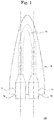
- Fig. 1 is a schematic diagram of a dialysis circuit priming device 100 according to one embodiment of the present invention.
- the dialysis circuit priming device 100 is arranged with a needle cap 10 which includes a flow path 13 connected to two needle connecting parts 11 each arranged with a needle 19 respectively.
- the needle 19 may be a puncturing needle comprised from an outer needle and an inner needle which are commonly used for in blood dialysis, or may be a butterfly needle or the like.
- a flow blocking means such as a clamp
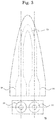
- Fig. 3 is a schematic diagram of a needle cap 10, the upper part shows an upper view of the needle cap 10, and the lower part shows a side view viewed from the needle connecting part 11 side.
- the needle cap 10 is, for example, made from a resin and can be formed by a known resin used for medical needle caps.
- the resin which forms the flow path 13 part preferably has flexibility. By providing the flow path par 13 with flexibility, in the case when the needle 19 and the flow path 13 are filled with saline, by clamping the flow path 13, it is possible to prevent air from entering the one needle 19 even when the other needle 19 is removed from the needle cap 10.
- the flow blocking means is not limited thereto, and a valve (not shown in the diagram) may be arranged in the flow path 13.
- the flow path 13 has a length which allows the needle connecting part 11 to be connected and the length of the flow path 13 is not particularly limited.
- the flow path 13 may further include an air reservoir.
- the needle connecting part 11 has a shape corresponding to the shape of the needle 19 and adhesion to the needle 19 is imparted to the needle cap 10.
- the needle connecting part 11 may also have a contact surface with the needle 19 having elasticity in order to improve adhesion with the needle 19.
- two needles 19 are shown in Fig. 1 having the same thickness, the present invention is not limited thereto, and the needles may each have different thickness.
- the dialysis circuit priming device 400 shown in Fig. 8 as a modified example in which each needle has a different thickness.
- the dialysis circuit priming device 400 is arranged with a needle 69a and a needle 69b having different thicknesses in a needle cap 60.
- a thick needle 69a is arranged on a needle connecting part 61a
- a thin needle 69b is arranged on a needle connecting part 61b.
- the flow path 63 connects the needle connecting part 61a having a thick needle 69a and the needle connecting part 61b having a thin needle 69b, a structure may be provided in which the diameter decreases toward the needle connecting part 61b from the needle connecting part 61a.
- the outer shape is not particularly limited, but from the view point of needle accident prevention, it is preferred that the needle cap 10 has a structure in which the two needles 19 are arranged in parallel or substantially parallel.
- the two needles 19 have such an arrangement, it is possible to provide a handle part on the side where the needles 19 of the needle cap 10 are arranged, improving retention when inserting and removing the needle 19, and it is possible to prevent needle accidents. Therefore, it is preferred to provide a sufficient size so that a user can hold the needle cap 10 on the side where the needles 19 of the needle cap 10 are arranged.
- FIG. 2 is a schematic diagram for explaining a priming method using the dialysis circuit priming device 100 according to one embodiment of the present invention. Since it is possible to use a blood circuit which is commercially available for medical use, although a detailed explained is omitted, in recent years there have been cases where a dialysate is supplied from a dialysis monitoring device or when pressure is applied to a dialysate connected to dialyzer and a priming solution is supplied into the blood circuit by reverse filtration, it is also possible to use the dialysis circuit priming device according the present invention for any method. A general method conventionally performed is described as an example. For example, a priming liquid container 1010, a blood dialyzer 1020, an artery chamber 1030, a vein chamber 1050 and a pump 1060 are arranged.
- the priming liquid container 1010 is connected to a line 1120 between an artery side connection part 1121 and the artery chamber 1030 through a priming liquid supply line 1111.
- the blood dialyzer 1020 is connected to the artery chamber 1030 via a line 1140 and connected to the vein chamber 1050 via a line 1150.
- the artery chamber 1030 is connected to one of the needles 19 arranged in the dialysis circuit priming device 100 through the vein side connection part 1161 of the line 1130.
- the vein chamber 1050 includes a line 1170 which drains a priming solution from the close blood circuit.
- the line 1170 is arranged with a valve 1171 and the priming solution can be drained from the blood circuit by opening the valve.
- vein chamber 1050 is connected to the other of the needles 19 arranged in the dialysis circuit priming device 100 via a line 1160.
- the pump 1060 is arranged in the artery chamber 1030 side (arterial side blood circuit) is shown in Fig. 2
- the present invention is not limited to this arrangement and the blood dialysis device in which the pump 1060 is arranged in the vein chamber 1050 side (artery side blood circuit) may be used.
- saline or dialysate and the like is supplied from the priming liquid container 1010 when the pump 1060 rotates. While a supplied liquid fills the artery chamber 1030, the blood dialyzer 1020 and the vein chamber 1050, it is possible for the liquid to flow around the closed circuit via a flow path (flow path 13 in Fig. 1 ) created by the present invention and perform washing and circuit filling. It is possible to discard the air and washed liquid within the circuit by discharging the air and injected liquid from the circuit through a tube from the vein chamber 1050 to the exterior of the circuit.
- the cleaning procedure of a blood circuit is carried out according to the operation procedure of a blood dialysis apparatus and blood circuit which are used.
- the dialysis circuit priming device 100 By using the dialysis circuit priming device 100 according to the present invention, it is possible to perform priming via the flow path 13 in a state in which it is connected with the needle 19, and it is possible to puncture the needle 19 in a dialysis patient after priming and start blood dialysis immediately.
- the dialysis circuit priming device 100 By simply connecting the dialysis circuit priming device 100 to a blood circuit, it is not necessary to perform an attachment operation of a needle after priming, and it is possible to provide a simple operation to users.
- the liquid in the circuit is generally extracted and discarded after the completion of the dialysis.
- a needle cap and a dialysis circuit priming device are provided with increased safety and convenience during an extraction operation after completion of a blood dialysis.
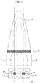
- Fig. 4 is a schematic diagram of a needle cap 20 according to one embodiment of the present invention.
- the needle cap 20 includes a flow path 23 which is connected to two needle connecting parts 21.
- the needle cap 20 is different from the needle cap 10 in that a film 25 for sealing the flow path 23 is arranged on the needle connecting part 21.
- the film 25 Since it is possible to use a known film which is used for a vial for injection liquids as the film 25, a detailed explanation is omitted.
- a structure is shown in Fig. 4 in which the film 25 is arranged on the entire surface of a cross section in a perpendicular direction to which the needle is inserted in the needle connecting part 21, the present embodiment is not limited to this and the film 25 may be arranged on only a cavity part of the needle connecting part 21.
- the film 25 is a flow blocking means which replaces a valve explained using the needle cap 20.
- Fig. 5 is a schematic diagram of a needle cap 30 according to another embodiment of the present invention.
- the needle cap 30 includes a flow path 33 which is connected to two needle connecting parts 31.
- the needle cap 30 differs from the needle cap 10 in that a threaded part 35 is arranged in the needle connecting part 31.
- the threaded part 35 has a shape corresponding to the thread of the needle. Therefore, a thread with a shape which latches with the threaded part 35 is also included in needle which is used in the present embodiment.
- the needle By rotating the needle in a range of 30° or more and 180° or less, the needle can be attached to and detached from the needle connecting part 31. It is preferred that the needle can be attached to and detached from the needle connecting part 31 in a rotation angle range of 45° or more and 90° or less.
- the threaded part 35 By arranging the threaded part 35 to the needle connecting part 31 in the needle cap 30, it is possible to prevent the needle from falling out of the needle connecting part 31. Since the remaining structure is the same as the needle cap 10 described above, a detailed explanation is omitted.
- Fig. 6 is a schematic diagram of a needle cap 40 according to another embodiment of the present invention.
- the needle cap 40 has two needle connecting parts 41 and a flow path 43 which connects to the two needle connecting parts 41.
- the needle cap 40 differs from the needle cap 10 in that a locking part 45 for locking an infusion stand is arranged.
- the locking part 45 is preferred to be arranged in the flow path 43 side (tip end part) of the needle cap 40 but is limited to this.
- the locking part 45 is preferred to have a structure so that it can be hooked on the infusion stand and may have a ring shaped structure.
- the size of the locking part 45 is not particularly limited as long as it can be hooked to the infusion stand and has the size and strength so that it is possible to lock the needle cap 40 in which a needle is connected to the artery side blood circuit and the vein side blood circuit. Since the remaining structure is the same as the needle cap 10 described above, a detailed explanation is omitted.
- Fig. 7 (a) is a schematic diagram showing a dialysis circuit priming device 200 arranged with a with butterfly needle 219 according to another embodiment of the present invention
- Fig. 7 (b) is a schematic diagram showing a dialysis circuit priming device 300 arranged with the butterfly needle 219 according to another embodiment of the present invention.
- the butterfly needle 219 has a pair of wing parts 218.
- the dialysis circuit priming device 200 has a structure in which the needle cap 10 described above is arranged with the butterfly needle 219.
- the wing parts 218 of two butterfly needles 219 are arranged to be parallel or substantially parallel so that each of the wing parts 218 of two butterfly needles 219 do not to interfere.
- each needle has a different thickness described above.
- the needle connecting part 51 is arranged in the needle cap 50 at a distance so that the wing parts 218 of the two butterfly needles 219 do not interfere.
- the flow path 53 is not particularly limited as long as it has a length which allows the two needle connecting parts 51 to be connected. Since the remaining structure is the same as the needle cap 10 described above, a detailed explanation is omitted.
- the needle cap 50 may be arranged with a film 25 explained in the needle cap 20, the threaded part 35 explained in the needle cap 30, or the locking part 45 explained in the needle cap 40, or may be arranged with a combination of these.
- the present invention is not limited to this, and one of the artery side connecting part 1121 and the vein side connecting part 1161 may be directly connected to the needle connecting part without passing through the needle.
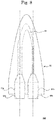
- Fig. 9 (a) is a schematic diagram of a needle cap 70 according to another embodiment of the present invention.
- the needle cap 70 includes two needle connecting parts 71 and a flow path 73 which is connected to the two needle connecting parts 71.
- the needle cap 70 has an arrangement in which the two needle connecting parts 71 are facing each other.
- the flow path 73 has a shape which linearly connects the two needle connecting parts 71.
- the needle cap 70 having such a structure can also be integrally molded. For example, it is possible to be formed by preparing a cylindrical needle cap and connecting the tip end parts of the needle caps.
- This type of needle cap 70 can also be carried out by a modified example such as the needle cap 80 shown in Fig. 9 (b) .
- the needle cap 80 includes a flow path 83 which is connected to the two needle connecting parts 81.
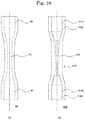
- the flow path 83 has a structure in which a diameter becomes narrower from one needle connecting part 81 toward the center of the flow path 83, and the diameter becomes thicker from the center of the flow path 83 towards the other needle connecting part 81.
- the needle cap 90 includes two needle connecting parts 91 and a flow path 93 which is connected to the two needle connecting parts 91.
- the flow path 93 has a structure in which the diameter becomes narrower from one of the needle connecting parts 91 to the center of the flow path 93, and the diameter becomes thicker from the center of the flow part 93 to the other needle connecting part 91.
- the needle cap 90 is different to the needle cap 80 in that the flow path 93 has a curved cross-section with respect to the center axis of the flow path 93, whereas the needle cap 80 is arranged with a flow path 83 having a linear cross-sectional shape.
- Fig. 10 (b) is a schematic diagram for explaining a dialysis circuit priming device 500 as a modified example.
- the dialysis circuit priming device 500 is arranged with a needle 519a and a needle 519b having different thicknesses in the needle cap 510.
- the flow path 513 connects the needle connecting part 511a which is arranged with a thick needle 519a and the needle connecting part 511b which is arranged with a thin needle 519b, it may have a structure in which the diameter becomes smaller from the needle connecting part 511a towards the needle connecting part 511b.
- the dialysis circuit priming device having an arrangement in which two needle connecting parts according to the present invention face each other is not limited to this structure, any of the needle cap 70 to the needle cap injections 90 can be applied.
- a film for sealing the flow path explained in the needle cap 20 may be arranged in a needle connecting part in the dialysis priming device according to the present invention having an arrangement in which two needle connecting parts face each other.
- the dialysis circuit priming device according to the present invention having an arrangement in which two needle connecting parts face each other may have a structure in which a threaded part is arranged on the needle connecting part explained in the needle cap 30.
- the needle cap according to the present invention Although an example of the needle cap according to the present invention described above was explained having a structure in which two needle connecting parts and a flow path connecting the two needle connecting parts are integrally formed, the needle cap according to the present invention is not limited to this structure. An explanation is given below of another modified example of a needle cap according to the present invention.
- Joint member 610 One end of the joint member 610 is locked with the needle cap 630a, and the other end is locked with the needle cap 630b.
- Each locking part 611 of the needle cap 630a and the needle cap 630b are respectively arranged at both ends of the joint member 610.
- Joint member 610 has a hollow structure including a flow path 613 which connects the locking parts 611 at both end parts.
- the joint member 610 is, for example, made of resin, and can be formed by a known resin which is used for the needle cap for medical application.
- the resin which forms the flow path 613 part has flexibility.
- the flow blocking means is not limited to this structure, and the flow path 613 may also be arranged with a valve (not shown in the diagram).
- the needle cap 630a is arranged with a needle connecting part 631a which is arranged with a needle 619a.
- the needle cap 630b is arranged with a needle connecting part 631b which is arranged with a needle 619b.
- a flow path 633a is arranged at the tip end part of the needle 619a.
- a flow path 633b is arranged at the tip end part of the needle 619b.
- the tip end part of the needle cap 630a and the needle cap 630b has a shape which locks with the lock part 611 of the joint member 610.
- the needle cap 630a and the needle cap 630b may be a cylindrical needle cap, and in this case, a tip end part of the needle cap 630a and the needle cap 630b has a cylindrical shape.
- the needle cap 630a and the needle cap 630b are, for example, made from a resin and can be formed by a known resin which is used for the needle caps for medical application.
- the dialysis circuit priming device 600 as explained in the dialysis circuit priming device 400, can be carried out as a modified example in which the needle cap 630a and the needle cap 630b have needles with different thicknesses.
- the cylindrical needle cap does not have any difference (or almost identical) in the thickness (diameter) of the tip end part even if the thickness of the needles is different.
- both ends of the locking part 611 of the joint member 610 may be the same diameter.
- the locking part 611 of the joint member 610 has a different thickness (diameter) than the other end, it is possible to lock even in the case when the thickness (diameter) of the tip end parts of the needle cap 630a and the needle cap 630b are different.
- a film which seals the flow path explained in the needle cap 20 may be arranged in the dialysis circuit priming device 600 according to the present invention having an arrangement in which the needle connecting part 631a and the needle connecting part 631b face each other.
- the dialysis circuit priming device 600 may have a structure in which a threaded part is arranged on the needle connecting part explained in the needle cap 30.
- the needle cap according to the present invention is not limited to this structure.
- An explanation is given below of a modified example of the dialysis circuit priming device 600.
- Fig. 12 is a schematic diagram for explaining a dialysis circuit priming device 700 according to one embodiment of the present invention.
- Fig. 12 (a) shows the dialysis circuit priming device 700
- Fig. 12 (b) shows a cross sectional view (upper diagram) taken along the center line in Fig. 12 (a) and a side surface view (lower diagram) seen from the center line direction.
- the dialysis circuit priming device 700 includes a needle cap 730a having a needle connecting part 731a arranged with a needle 719a, and a needle cap 730b having a needle connecting part 731b arranged with a needle 719b.
- the dialysis circuit priming device 700 is further arranged with a joint member 710 for connecting the needle cap 730a and the needle cap 730b.
- the joint member 710 locks with the needle cap 730a and the other end locks with the needle cap 730b.
- the locking part 711 which respectively locks the needle cap 730a and the needle cap 730b is arranged at both ends of the joint member 710.
- the joint member 710 has a hollow structure including a flow path 713 which connects the locking part 711 at both end parts.
- the locking part 711 has a threaded part.
- the threaded part of the locking part 711 has a shape corresponding to the threaded part of the needle cap 730a and the needle cap 730b described herein.
- the dialysis circuit priming device 700 is arranged with the threaded part to the locking part 711 of the joint member 710, and thereby the needle cap 730a and the needle cap 730b can be prevented from falling from the joint member 710. Since the remaining structure is the same as the dialysis circuit priming device 600 described above, a detailed explanation is omitted.
- Fig. 13 is a schematic diagram for explaining a needle cap 730 according to one embodiment of the present invention.
- the needle cap 730a is arranged with a needle connecting part 731a including a needle 719a.
- the needle cap 730b is arranged with a needle connecting part 731b including a needle 719b.
- a flow path 733a is arranged at the tip end part of the needle 719a.
- a flow path 733b is arranged at the tip end part of the needle 719b.
- the tip end part of the needle cap 730a and the needle cap 730b includes a threaded part 735 which locks with the locking part 711 of the joint member 710.
- the needle cap 730a and the needle cap 730b are, for example, made of a resin, and can be formed by a known resin used for needle cap for medical applications.
- the opening of the flow path 733 may be sealed by placing a cap on the threaded part 735 during use.
- the dialysis circuit priming device 700 as explained in the dialysis circuit priming device 400, can be carried out as a modified example in which the needle cap 730a and the injection needle cap 730b have a needles with different thicknesses. Both end parts of the locking part 711 of the joint member 710 may have the same diameter. In addition, by making one end of the locking part 711 a different thickness (diameter) than the other end, it is possible to lock even in the case where the thickness (diameter) of the tip end parts of the needle cap 730a and the needle cap 730b are different.
- a film which seals the flow path explained in the needle cap 20 may be arranged in the dialysis circuit priming device 700 according to the present invention having an arrangement in which the needle connecting part 731a and the needle connecting part 731b face each other.
- the dialysis circuit priming device 700 may have a structure in which a threaded part is arranged on the needle connecting part explained in the needle cap 30.
- Fig. 14 (a) is a diagram showing a dialysis circuit priming device 800
- Fig. 14 (b) is a cross sectional diagram of a segment AB in the vicinity of the needle connecting part 811 surrounded by a broken line shown in Fig. 14 (a)
- the dialysis circuit priming device 800 is arranged with a needle cap 810 having a flow path 813 which is connected to two needle connecting parts 811 which are arranged respectively with a needle 819.
- a needle 819 is preferred to be a butterfly shape as an example from the view point of simplicity of puncture procedure, it is not limited to this shape.
- the needle 819 has a wing part 818a and a wing part 818b on the needle hub 819b for holding the needle body 819a.
- an example of the dialysis circuit priming device 800 having a tube 830 is shown. A first end of the tube 830 is connected to the needle hub 819b, and a second end is connected to a connector 831.
- the connector 831 is protected by a cap 833.
- the tube 830 may be arranged with a Robert clamp 840 for example.
- the flow path 813 is formed from a tube and has flexibility, it is possible to freely change each arrangement of the two needle bodies 819a via the flow path 813, it is possible to hook it to an infusion stand, and it is possible to reduce the size of the packaging.
- the flow path 813 is preferred to have any length so that it can be hooked to the infusion stand, and has a hardness so that the flow path 813 is not blocked when the tube bends when hooked to the infusion stand.
- the flow path 813 and the needle hub 819b are fixed at each end of the needle connecting part 811, and the needle connecting part 811 has an internal structure that covers the entire needle body 819a.
- the needle connecting part 811 may be molded including a weak part, it may also be formed by fixing or assembling a plurality of members, or a part which is assembled or fixed may be a weak part.
- a flexible tube as a flow path 813, it is not essential. For example, it is possible to hook to an infusion stand by forming the entire flow path 813 from a hard material as an arrangement in which two needle bodies 819a are in parallel or substantially parallel.
- the tube 830 is formed by a known resin material and is not particularly limited.
- the connector 831 is a terminal for connecting to a blood circuit and is not particularly limited.
- the present invention may be directly connected to an end part of the blood circuit without going through the connector 831.
- the cap 833 is connected to the connector 831, and can be removed from the connector 831 when the connector 831 is connected to a blood circuit, and is not particularly limited.
- Fig. 15 (a) is a schematic diagram showing a state in which the needle cap 810 is removed from the dialysis circuit priming device 800 according to one embodiment of the present invention.
- Fig. 15 (b) is a cross sectional diagram in the segment AB of the needle 819 surrounded by a broken line in Fig. 15 (a) .
- a part of the needle connecting part 811 which is broken by the weak part 812 is located in the vicinity of the needle hub 819b.
- the wing part 818a and wing part818b may be held with one hand and bent in a direction substantially perpendicular (Z-direction in Fig. 16 (a) ) with respect to the wing part 818a and wing part 818b, and by holding the needle connecting part 811 with the other hand and performing relative rotation, it is possible to tear the weak part 812 and separate the needle connecting part 811 from the needle 819.
- the needle connecting part 811 for example, has a flat plate shaped structure which is easily held, and the weak part 812 is easy to tear which is preferred.
- each end part of the needle connecting part 811 in the present embodiment is a cylindrical part, and a flow path or needle hub is inserted into each end part.
- the outer surface has a flat plate part between cylindrical parts.
- the flat plate part has a hollow shape having a tapered structure which decreases in diameter toward the needle hub side, and the needle body 819a is located inside.
- the external shape of the flat plate part has a planar view elliptical shape and a side view biconcave shape from the viewpoint of usability.
- the flat plate part has a surface that intersects a surface of the wing part 818a and wing part 818b in a state held by one hand, and the flat plate shaped part is easily rotated in a state where the wing parts are held with one hand.
- the flat plate shaped part has a structure having a surface parallel to the wing part 818a and wing part 818b in a state before being held with a hand.
- the shape of the needle connecting part 811 may be a structure which is easily held and is easy to tear the weak part 812 but is not limited to this shape.
- a flat plate part can be a cylindrical shape which has ribs.
- the needle connecting part 811 is preferred to be easy to hold and is formed of a material having sufficient rigidity in order to protect the needle body 819a.
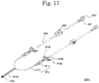
- Fig. 17 is a schematic diagram of a dialysis circuit priming device 800a according to a modified example.
- the dialysis circuit priming device 800a is different from the dialysis circuit priming device 800 in that it includes a drain path 813a in a flow path 813.
- a cap 835 is arranged at the end part of the drain path 813a.
- Fig. 18 is a schematic diagram for explaining a modified example using a dialysis circuit priming device 800.
- a branch tube 870 is connected to a connector 831 of the dialysis circuit priming device 800.
- a first end part 871 of the branch tube 870 is connected to the connector 831, a second end part 873 is connected to the blood circuit, and it is possible to use the third end part 875 as a drain path. Since the same structure as the dialysis circuit priming device 800 described above can be used for the remaining structure, a detailed explanation is omitted.
Landscapes
- Health & Medical Sciences (AREA)
- Heart & Thoracic Surgery (AREA)
- Vascular Medicine (AREA)
- Hematology (AREA)
- Biomedical Technology (AREA)
- Anesthesiology (AREA)
- Engineering & Computer Science (AREA)
- Life Sciences & Earth Sciences (AREA)
- Animal Behavior & Ethology (AREA)
- General Health & Medical Sciences (AREA)
- Public Health (AREA)
- Veterinary Medicine (AREA)
- Cardiology (AREA)
- External Artificial Organs (AREA)
Abstract
Description
- The present invention relates to a cap for injection needles and a device for dialysis circuit priming.
- When a renal function is reduced it is necessary to remove uremic toxins from the blood. As a result, blood dialysis has become a global mainstream treatment for removing uremic toxins from the blood. In a blood dialysis, two needles are inserted into a blood vessel, uremic toxins are removed by extracting blood via a tube connected to one of the needles and passing the blood through a dialyzer, and returning the blood into the body via a tube connected to the other needle. A dialysis blood circuit is one route which is closed, and it is necessary to fill up the route with saline or dialysate at the start of dialysis. The artery side access part (arterial side) which is used in the following explanation means a bonding part between an artery side circuit and an artery side vascular access device, and a vein side access part (venous side) means a bonding part between a vein side circuit and a vein side vascular access device.
- In order to remove fine dust within a dialyzer and a blood circuit, remove a film protective agent and remove a filling liquid and air by washing and return it to a state in which the treatment can be started, it is necessary to prepare the circuit before starting dialysis and perform cleaning in the blood circuit and priming the blood circuit. Cleaning and priming are performed according to the method described in the instruction manual of the dialyzer. This work is preferably carried out immediately before starting dialysis, and has been conventionally performed by the hand of the medical practitioner by the method described below.
- The dialyzer and a blood circuit are properly connected. At this time, it is important to not touch the connection of the blood circuit and the dialyzer with hands or forceps. The artery side blood circuit is filled with saline using a saline connected to a priming line or a replacement fluid line and connected to the arterial side of the dialyzer. Next, the vein side blood circuit is connected in the venous side of the dialyzer. The order this task is performed in may be changed according to the type of dialyzer in order to prevent air contamination. When all connections are finished, the dialyzer and blood circuit are flushed with saline and cleaned. After cleaning is completed, the inside of the blood circuit and the dialyzer are replaced with filling saline, and a soft packed saline for rehydration and returning blood after replacement is substituted. The cleaning and priming operation is performed by skilled staff who sufficiently understands the concept of hygiene in medicine.
- Today's dialysis monitoring devices have evolved in which a method for creating a closed circuit by connecting two routes of an arterial side and a venous side to be connected to the patient, and automatically filling with saline or dialysate has become mainstream. By this method, it is possible to securely clean the dialyzer. However, since the two routes (tubes) of the arterial side and venous side are connected when dialysis is started, it is necessary to separate them and connect a needle respectively.
- For example, Patent Literature 1 describes a blood cleaning device arranged with a Y shaped tube which can be connected to a drain line and in which an artery side needle connection end and a vein side needle connection end are mutually connected to a drain path.
- Patent Literature 1: Japanese Laid Open Patent Publication No.
2012-139405 - It is desirable to safely and conveniently perform attachment of a needle after cleaning and priming of a blood circuit from the viewpoint of reducing the workload burden of medical staff, needle penetration accidents and the risk of infections.
- The present invention has been made to solve the problems described above and provides a needle cap and a dialysis circuit priming device with increased safety and convenience in the cleaning and priming of a blood circuit.
- According to one embodiment of the present invention, a needle cap is provided including two needle connecting parts, and a flow path connecting the two needle connecting parts.
- The needle cap may also include a weak part in the two needle connecting parts.
- The needle cap may also include a film arranged in the needle connecting part for sealing the flow path.
- The needle cap may also include a threaded part in the needle connecting part.
- The needle cap may also include a locking part for locking an infusion stand.
- In addition, according to one embodiment of the invention, a dialysis circuit priming device is provided including two needles, two needle connecting parts each arranged with the two needles respectively, and a flow path for connecting the two needle connecting parts.
- The dialysis circuit priming device may also include a weak part in the two needle connecting parts.
- The dialysis circuit priming device may also include a film arranged in the needle connecting part for sealing the flow path.
- The dialysis circuit priming device may also include a threaded part arranged respectively on the two needles and the needle connecting part, wherein the two needles are screwed into the needle connecting parts.
- The dialysis circuit priming device may also include a locking part for locking an infusion stand.
- The dialysis circuit priming device may also include a butterfly shaped needle.
- In addition, according to one embodiment of the present invention, a dialysis circuit priming device is provided including a first injection needle cap and a second injection needle cap arranged with a needle and a needle connecting part arranged with the needle, a joint member locking the first needle cap and the second needle cap, and a flow path connected to two of the needle connecting parts.
- The dialysis circuit priming device may also include a thread arranged on a tip end part of the first needle cap and the second needle cap, wherein a joint part of the joint member for locking the first needle cap and the second needle cap is arranged with a thread.
- According to the present invention, a needle cap and a dialysis circuit priming device are provided with increased safety and convenience in the cleaning and priming of a blood circuit.
-
- [
Fig. 1] Fig. 1 is a schematic diagram of a dialysiscircuit priming device 100 according to one embodiment of the present invention. - [
Fig. 2] Fig. 2 is a schematic diagram for explaining a priming method using the dialysiscircuit priming device 100 according to one embodiment of the present invention. - [
Fig. 3] Fig. 3 is a schematic diagram of a needle cap according to one embodiment of the present invention. - [
Fig. 4] Fig. 4 is a schematic diagram of a needle cap according to one embodiment of the present invention. - [
Fig. 5] Fig. 5 is a schematic diagram of a needle cap according to one embodiment of the present invention. - [
Fig. 6] Fig. 6 is a schematic diagram of a needle cap according to one embodiment of the present invention. - [
Fig. 7 ] (a) is a schematic diagram of the dialysiscircuit priming device 100 according to one embodiment of the present invention, (b) is a schematic diagram of a dialysiscircuit priming device 300 according to one embodiment of the present invention. - [
Fig. 8] Fig. 8 is a schematic diagram of a dialysiscircuit priming device 400 according to one embodiment of the present invention. - [
Fig. 9 ] (a) is a schematic diagram of aneedle cap 70 according to one embodiment of the present invention, (b) is a schematic diagram of aneedle cap 80 according to one embodiment of the present invention. - [
Fig. 10 ] (a) is a schematic diagram of aneedle cap 90 according to one embodiment of the present invention, (b) is a schematic diagram of dialysiscircuit priming device 500 according to one embodiment of the present invention. - [
Fig. 11 ] shows a dialysiscircuit priming device 600, (b) shows a cross sectional diagram taken along a center line of (a) (upper diagram) and a side surface diagram as seen from the center line direction (lower diagram). - [
Fig. 12 ] (a) shows a dialysiscircuit priming device 700, (b) shows a cross sectional diagram taken along a center line of (a) (upper diagram) and a side surface diagram as seen from the center line direction (lower diagram). - [
Fig. 13] Fig. 13 is a schematic diagram for explaining aneedle cap 730 according to one embodiment of the present invention. - [
Fig. 14 ] (a) is a schematic diagram of a dialysiscircuit priming device 800 according to one embodiment of the present invention, (b) is a cross sectional diagram in a segment AB near aneedle connecting part 811 surrounded by the broken line in (a). - [
Fig. 15 ] (a) is a schematic diagram showing a state in which aneedle cap 810 is removed from the dialysiscircuit priming device 800 according to one embodiment of the present invention, (b) is a cross sectional diagram of aneedle 811 in a segment AB surrounded by the broken line in (a). - [
Fig. 16 ] (a) is a schematic diagram for explaining a method of removing aneedle cap 810 from the dialysiscircuit priming device 800 according to one embodiment of the present invention, (b) is a schematic diagram showing a state in which theneedle cap 810 is removed. - [
Fig. 17] Fig. 17 is a schematic diagram of a dialysiscircuit priming device 800a according to a modified example of the present invention. - [
Fig. 18] Fig. 18 is a schematic diagram for explaining a modified example using the dialysiscircuit priming device 800 of the present invention. - A needle cap and a dialysis circuit priming device according to the present invention is explained herein while referring to the drawings. The cap for injection needles and dialysis circuit priming device according to the present invention should be construed as being limited to the described contents of the embodiments below. Furthermore, in the drawings referred to in the present embodiment, the same parts or parts which have similar functions are denoted by the same reference numerals and a repeated explanation thereof is omitted.
-
Fig. 1 is a schematic diagram of a dialysiscircuit priming device 100 according to one embodiment of the present invention. The dialysiscircuit priming device 100 is arranged with aneedle cap 10 which includes aflow path 13 connected to twoneedle connecting parts 11 each arranged with aneedle 19 respectively. Theneedle 19 may be a puncturing needle comprised from an outer needle and an inner needle which are commonly used for in blood dialysis, or may be a butterfly needle or the like. By arranging a flow blocking means such as a clamp to theflow path 13, it is possible to prevent the mixing of air into one of theneedles 19 and the dialysis circuit even after removing theother needle 19. -
Fig. 3 is a schematic diagram of aneedle cap 10, the upper part shows an upper view of theneedle cap 10, and the lower part shows a side view viewed from theneedle connecting part 11 side. Theneedle cap 10 is, for example, made from a resin and can be formed by a known resin used for medical needle caps. In addition, the resin which forms theflow path 13 part preferably has flexibility. By providing the flow path par 13 with flexibility, in the case when theneedle 19 and theflow path 13 are filled with saline, by clamping theflow path 13, it is possible to prevent air from entering the oneneedle 19 even when theother needle 19 is removed from theneedle cap 10. In theneedle cap 10 according to the present invention, the flow blocking means is not limited thereto, and a valve (not shown in the diagram) may be arranged in theflow path 13. - In addition, it is sufficient that the
flow path 13 has a length which allows theneedle connecting part 11 to be connected and the length of theflow path 13 is not particularly limited. Theflow path 13 may further include an air reservoir. - In addition, the
needle connecting part 11 has a shape corresponding to the shape of theneedle 19 and adhesion to theneedle 19 is imparted to theneedle cap 10. In addition, theneedle connecting part 11 may also have a contact surface with theneedle 19 having elasticity in order to improve adhesion with theneedle 19. Although twoneedles 19 are shown inFig. 1 having the same thickness, the present invention is not limited thereto, and the needles may each have different thickness. - In addition, for example, it is possible to use the dialysis
circuit priming device 400 shown inFig. 8 as a modified example in which each needle has a different thickness. The dialysiscircuit priming device 400 is arranged with aneedle 69a and aneedle 69b having different thicknesses in aneedle cap 60. InFig. 8 , as an example, athick needle 69a is arranged on a needle connecting part 61a, and athin needle 69b is arranged on aneedle connecting part 61b. Here, since theflow path 63 connects the needle connecting part 61a having athick needle 69a and theneedle connecting part 61b having athin needle 69b, a structure may be provided in which the diameter decreases toward theneedle connecting part 61b from the needle connecting part 61a. - In addition, if the
needle cap 10 has a structure including theflow path 13 connected to the twoneedle connecting parts 11, then the outer shape is not particularly limited, but from the view point of needle accident prevention, it is preferred that theneedle cap 10 has a structure in which the twoneedles 19 are arranged in parallel or substantially parallel. When the twoneedles 19 have such an arrangement, it is possible to provide a handle part on the side where theneedles 19 of theneedle cap 10 are arranged, improving retention when inserting and removing theneedle 19, and it is possible to prevent needle accidents. Therefore, it is preferred to provide a sufficient size so that a user can hold theneedle cap 10 on the side where theneedles 19 of theneedle cap 10 are arranged. - A cleaning and priming method of a blood circuit using the dialysis
circuit priming device 100 according to the present invention is explained while referring toFig. 2. Fig. 2 is a schematic diagram for explaining a priming method using the dialysiscircuit priming device 100 according to one embodiment of the present invention. Since it is possible to use a blood circuit which is commercially available for medical use, although a detailed explained is omitted, in recent years there have been cases where a dialysate is supplied from a dialysis monitoring device or when pressure is applied to a dialysate connected to dialyzer and a priming solution is supplied into the blood circuit by reverse filtration, it is also possible to use the dialysis circuit priming device according the present invention for any method. A general method conventionally performed is described as an example. For example, a primingliquid container 1010, ablood dialyzer 1020, anartery chamber 1030, avein chamber 1050 and apump 1060 are arranged. - The priming
liquid container 1010 is connected to aline 1120 between an arteryside connection part 1121 and theartery chamber 1030 through a priming liquid supply line 1111. Theblood dialyzer 1020 is connected to theartery chamber 1030 via aline 1140 and connected to thevein chamber 1050 via aline 1150. Theartery chamber 1030 is connected to one of theneedles 19 arranged in the dialysiscircuit priming device 100 through the veinside connection part 1161 of theline 1130. Thevein chamber 1050 includes aline 1170 which drains a priming solution from the close blood circuit. Theline 1170 is arranged with avalve 1171 and the priming solution can be drained from the blood circuit by opening the valve. In addition, thevein chamber 1050 is connected to the other of theneedles 19 arranged in the dialysiscircuit priming device 100 via aline 1160. Furthermore, although an example in which thepump 1060 is arranged in theartery chamber 1030 side (arterial side blood circuit) is shown inFig. 2 , the present invention is not limited to this arrangement and the blood dialysis device in which thepump 1060 is arranged in thevein chamber 1050 side (artery side blood circuit) may be used. - After the blood circuit is connected, saline or dialysate and the like is supplied from the priming
liquid container 1010 when thepump 1060 rotates. While a supplied liquid fills theartery chamber 1030, theblood dialyzer 1020 and thevein chamber 1050, it is possible for the liquid to flow around the closed circuit via a flow path (flowpath 13 inFig. 1 ) created by the present invention and perform washing and circuit filling. It is possible to discard the air and washed liquid within the circuit by discharging the air and injected liquid from the circuit through a tube from thevein chamber 1050 to the exterior of the circuit. - The cleaning procedure of a blood circuit is carried out according to the operation procedure of a blood dialysis apparatus and blood circuit which are used. By using the dialysis
circuit priming device 100 according to the present invention, it is possible to perform priming via theflow path 13 in a state in which it is connected with theneedle 19, and it is possible to puncture theneedle 19 in a dialysis patient after priming and start blood dialysis immediately. As a result, by simply connecting the dialysiscircuit priming device 100 to a blood circuit, it is not necessary to perform an attachment operation of a needle after priming, and it is possible to provide a simple operation to users. - In addition, the liquid in the circuit is generally extracted and discarded after the completion of the dialysis. In this case, after completion of the dialysis, it is necessary to extract saline or dialysate remaining in the blood circuit due to blood return from the blood circuit. As a result, conventionally, it was necessary to remove the two needles and connect the ends at the artery side and vein side in the blood circuit to each other. As a result, it is desirable to safely and conveniently perform the removal of needles when performing an extraction operation after completion of the blood dialysis and a reconnection operation of the artery side blood circuit and the vein side blood circuit. As a result, in one embodiment, a needle cap and a dialysis circuit priming device are provided with increased safety and convenience during an extraction operation after completion of a blood dialysis. In one embodiment, it is possible to perform an extraction process by again returning both needles to the device according to the present invention. Following this, it is possible to prevent the needle accidents which are likely to occur during a process such as removing the needle by cutting a tube connected to the device of present invention with scissors or the like. According to the present invention, it is also possible to provide a needle cap and a dialysis circuit priming device with increased safety and convenience during an extraction operation after completion of blood dialysis.
- The needle cap according to the present invention is further explained.
Fig. 4 is a schematic diagram of aneedle cap 20 according to one embodiment of the present invention. Theneedle cap 20 includes aflow path 23 which is connected to twoneedle connecting parts 21. In addition, theneedle cap 20 is different from theneedle cap 10 in that afilm 25 for sealing theflow path 23 is arranged on theneedle connecting part 21. - Since it is possible to use a known film which is used for a vial for injection liquids as the
film 25, a detailed explanation is omitted. In addition, although a structure is shown inFig. 4 in which thefilm 25 is arranged on the entire surface of a cross section in a perpendicular direction to which the needle is inserted in theneedle connecting part 21, the present embodiment is not limited to this and thefilm 25 may be arranged on only a cavity part of theneedle connecting part 21. In theneedle cap 20, thefilm 25 is a flow blocking means which replaces a valve explained using theneedle cap 20. By providing thefilm 25, in the case when theneedle 19 and theflow path 13 are filled with a saline, even when oneneedle 19 is removed from theneedle cap 10, it is possible to block air entering into theflow path 23 by thefilm 25, and prevent air entering theother needle 19. Since the remaining structure is the same as theneedle cap 10 described above, a detailed explanation is omitted. It is also possible to apply the modified example having needles each with different thickness described above. -
Fig. 5 is a schematic diagram of aneedle cap 30 according to another embodiment of the present invention. Theneedle cap 30 includes aflow path 33 which is connected to twoneedle connecting parts 31. In addition, theneedle cap 30 differs from theneedle cap 10 in that a threadedpart 35 is arranged in theneedle connecting part 31. By arranging a clamp to theflow path 33, it is possible to prevent air from being mixed into the other needle and the blood circuit even after removing one of the needles. - The threaded
part 35 has a shape corresponding to the thread of the needle. Therefore, a thread with a shape which latches with the threadedpart 35 is also included in needle which is used in the present embodiment. By rotating the needle in a range of 30° or more and 180° or less, the needle can be attached to and detached from theneedle connecting part 31. It is preferred that the needle can be attached to and detached from theneedle connecting part 31 in a rotation angle range of 45° or more and 90° or less. By arranging the threadedpart 35 to theneedle connecting part 31 in theneedle cap 30, it is possible to prevent the needle from falling out of theneedle connecting part 31. Since the remaining structure is the same as theneedle cap 10 described above, a detailed explanation is omitted. Furthermore, it is also possible to arrange theneedle cap 20 described above with a structure having a threadedpart 35. In addition, it is also possible to apply the modified example in which each needle has a different thickness described above. -
Fig. 6 is a schematic diagram of aneedle cap 40 according to another embodiment of the present invention. Theneedle cap 40 has twoneedle connecting parts 41 and aflow path 43 which connects to the twoneedle connecting parts 41. In addition, theneedle cap 40 differs from theneedle cap 10 in that a lockingpart 45 for locking an infusion stand is arranged. - The locking
part 45 is preferred to be arranged in theflow path 43 side (tip end part) of theneedle cap 40 but is limited to this. The lockingpart 45 is preferred to have a structure so that it can be hooked on the infusion stand and may have a ring shaped structure. The size of the lockingpart 45 is not particularly limited as long as it can be hooked to the infusion stand and has the size and strength so that it is possible to lock theneedle cap 40 in which a needle is connected to the artery side blood circuit and the vein side blood circuit. Since the remaining structure is the same as theneedle cap 10 described above, a detailed explanation is omitted. Furthermore, it is also possible to arrange theneedle cap 20 and theneedle cap 30 described above with a structure including the lockingpart 45. In addition, it is also possible to apply the modified example in which each needle has a different thickness described above. -
Fig. 7 (a) is a schematic diagram showing a dialysiscircuit priming device 200 arranged with a withbutterfly needle 219 according to another embodiment of the present invention, andFig. 7 (b) is a schematic diagram showing a dialysiscircuit priming device 300 arranged with thebutterfly needle 219 according to another embodiment of the present invention. - The
butterfly needle 219 has a pair ofwing parts 218. The dialysiscircuit priming device 200 has a structure in which theneedle cap 10 described above is arranged with thebutterfly needle 219. In the dialysiscircuit priming device 200, thewing parts 218 of two butterfly needles 219 are arranged to be parallel or substantially parallel so that each of thewing parts 218 of two butterfly needles 219 do not to interfere. Furthermore, it is also possible to use theneedle cap 20 or theneedle cap 40 described above instead of theneedle cap 10. In addition, it is also possible to apply the modified example in which each needle has a different thickness described above. - On the other hand, in the dialysis
circuit priming device 300, theneedle connecting part 51 is arranged in theneedle cap 50 at a distance so that thewing parts 218 of the two butterfly needles 219 do not interfere. The flow path 53 is not particularly limited as long as it has a length which allows the twoneedle connecting parts 51 to be connected. Since the remaining structure is the same as theneedle cap 10 described above, a detailed explanation is omitted. Furthermore, theneedle cap 50 may be arranged with afilm 25 explained in theneedle cap 20, the threadedpart 35 explained in theneedle cap 30, or the lockingpart 45 explained in theneedle cap 40, or may be arranged with a combination of these. In addition, it is also possible to apply the modified example in which each needle has a different thickness described above. - Furthermore, in the embodiments described above, although an example is shown in which two needles are arranged in the needle cap according to the present invention, the present invention is not limited to this, and one of the artery
side connecting part 1121 and the veinside connecting part 1161 may be directly connected to the needle connecting part without passing through the needle. -
Fig. 9 (a) is a schematic diagram of aneedle cap 70 according to another embodiment of the present invention. Theneedle cap 70 includes twoneedle connecting parts 71 and aflow path 73 which is connected to the twoneedle connecting parts 71. Although an example having an arrangement in which the two needle connecting parts are parallel or substantially parallel is shown in the embodiment described above, theneedle cap 70 has an arrangement in which the twoneedle connecting parts 71 are facing each other. As a result, theflow path 73 has a shape which linearly connects the twoneedle connecting parts 71. Theneedle cap 70 having such a structure can also be integrally molded. For example, it is possible to be formed by preparing a cylindrical needle cap and connecting the tip end parts of the needle caps. - This type of
needle cap 70, for example, can also be carried out by a modified example such as theneedle cap 80 shown inFig. 9 (b) . Theneedle cap 80 includes aflow path 83 which is connected to the twoneedle connecting parts 81. Theflow path 83 has a structure in which a diameter becomes narrower from oneneedle connecting part 81 toward the center of theflow path 83, and the diameter becomes thicker from the center of theflow path 83 towards the otherneedle connecting part 81. - In addition, it is also possible to be carried out by a modified example such as a
needle cap 90 shown inFig. 10 (a) . Theneedle cap 90 includes twoneedle connecting parts 91 and aflow path 93 which is connected to the twoneedle connecting parts 91. Theflow path 93 has a structure in which the diameter becomes narrower from one of theneedle connecting parts 91 to the center of theflow path 93, and the diameter becomes thicker from the center of theflow part 93 to the otherneedle connecting part 91. Here, theneedle cap 90 is different to theneedle cap 80 in that theflow path 93 has a curved cross-section with respect to the center axis of theflow path 93, whereas theneedle cap 80 is arranged with aflow path 83 having a linear cross-sectional shape. - Furthermore, the
needle cap 70 to theneedle cap 90 described above, can also be carried out implemented as a modified example having each needle with different thicknesses as explained in the dialysiscircuit priming device 400.Fig. 10 (b) is a schematic diagram for explaining a dialysiscircuit priming device 500 as a modified example. The dialysiscircuit priming device 500 is arranged with aneedle 519a and aneedle 519b having different thicknesses in theneedle cap 510. Here, since theflow path 513 connects theneedle connecting part 511a which is arranged with athick needle 519a and theneedle connecting part 511b which is arranged with athin needle 519b, it may have a structure in which the diameter becomes smaller from theneedle connecting part 511a towards theneedle connecting part 511b. The dialysis circuit priming device having an arrangement in which two needle connecting parts according to the present invention face each other is not limited to this structure, any of theneedle cap 70 to theneedle cap injections 90 can be applied. - In addition, a film for sealing the flow path explained in the
needle cap 20 may be arranged in a needle connecting part in the dialysis priming device according to the present invention having an arrangement in which two needle connecting parts face each other. Furthermore, the dialysis circuit priming device according to the present invention having an arrangement in which two needle connecting parts face each other may have a structure in which a threaded part is arranged on the needle connecting part explained in theneedle cap 30. - Although an example of the needle cap according to the present invention described above was explained having a structure in which two needle connecting parts and a flow path connecting the two needle connecting parts are integrally formed, the needle cap according to the present invention is not limited to this structure. An explanation is given below of another modified example of a needle cap according to the present invention.
-
Fig. 11 is a schematic diagram for explaining a dialysiscircuit priming device 600 according to one embodiment of the present invention.Fig. 11 (a) shows the dialysiscircuit priming device 600, andFig. 11 (b) shows a cross sectional view (upper diagram) taken along the center line ofFig. 11 (a) and shows a side surface view (lower diagram) seen from the center line direction. The dialysiscircuit priming device 600 is arranged with aneedle cap 630a including aneedle connecting part 631a arranged with aneedle 619a, and aneedle cap 630b including aneedle connecting part 631b arranged with aneedle 619b. The dialysiscircuit priming device 600 is further arranged with ajoint member 610 for connecting theneedle cap 630a and theneedle cap 630b. - One end of the
joint member 610 is locked with theneedle cap 630a, and the other end is locked with theneedle cap 630b. Each lockingpart 611 of theneedle cap 630a and theneedle cap 630b are respectively arranged at both ends of thejoint member 610.Joint member 610 has a hollow structure including aflow path 613 which connects the lockingparts 611 at both end parts. - The
joint member 610 is, for example, made of resin, and can be formed by a known resin which is used for the needle cap for medical application. In addition, it is preferred that the resin which forms theflow path 613 part has flexibility. By providing theflow path 613 part with flexibility, in the case where theneedle 619a, theneedle 619b and theflow path 613 are filled with saline, by clamping theflow path 613, it is possible to prevent the entry of air into the other needle 619 even if theneedle 619a or theneedle 619b is removed from theneedle cap 630a orneedle cap injections 630b which connect theneedles 619a orneedle 619b. In thejoint member 610 according to the present invention, the flow blocking means is not limited to this structure, and theflow path 613 may also be arranged with a valve (not shown in the diagram). - The
needle cap 630a is arranged with aneedle connecting part 631a which is arranged with aneedle 619a. In addition, theneedle cap 630b is arranged with aneedle connecting part 631b which is arranged with aneedle 619b. Aflow path 633a is arranged at the tip end part of theneedle 619a. In addition, aflow path 633b is arranged at the tip end part of theneedle 619b. By arranging theneedle cap 630a and theneedle cap 630b at both ends of thejoint member 610, theflow path 633a and theflow path 633b are connected to theflow path 613 to form one flow path. - The tip end part of the
needle cap 630a and theneedle cap 630b has a shape which locks with thelock part 611 of thejoint member 610. Theneedle cap 630a and theneedle cap 630b may be a cylindrical needle cap, and in this case, a tip end part of theneedle cap 630a and theneedle cap 630b has a cylindrical shape. Theneedle cap 630a and theneedle cap 630b are, for example, made from a resin and can be formed by a known resin which is used for the needle caps for medical application. - In addition, the dialysis
circuit priming device 600, as explained in the dialysiscircuit priming device 400, can be carried out as a modified example in which theneedle cap 630a and theneedle cap 630b have needles with different thicknesses. The cylindrical needle cap does not have any difference (or almost identical) in the thickness (diameter) of the tip end part even if the thickness of the needles is different. As a result, both ends of the lockingpart 611 of thejoint member 610 may be the same diameter. In addition, when one end of the lockingpart 611 of thejoint member 610 has a different thickness (diameter) than the other end, it is possible to lock even in the case when the thickness (diameter) of the tip end parts of theneedle cap 630a and theneedle cap 630b are different. - In the present embodiment, in the case when a cylindrical needle cap is used for the
needle cap 630a and theneedle cap 630b, the tip end part of the needle cap (from the tip to the open position of the flow path 633) is cut and the tip end part of the needle cap is opened. The opened tip end part of the needle cap (needle cap 630a andneedle cap 630b) respectively lock the both end parts of the lockingpart 611 of thejoint member 610. - In addition, a film which seals the flow path explained in the
needle cap 20 may be arranged in the dialysiscircuit priming device 600 according to the present invention having an arrangement in which theneedle connecting part 631a and theneedle connecting part 631b face each other. Furthermore, the dialysiscircuit priming device 600 may have a structure in which a threaded part is arranged on the needle connecting part explained in theneedle cap 30. - Although an example was explained in which two
needle caps circuit priming device 600 according to the present invention described above, the needle cap according to the present invention is not limited to this structure. An explanation is given below of a modified example of the dialysiscircuit priming device 600. -
Fig. 12 is a schematic diagram for explaining a dialysiscircuit priming device 700 according to one embodiment of the present invention.Fig. 12 (a) shows the dialysiscircuit priming device 700, andFig. 12 (b) shows a cross sectional view (upper diagram) taken along the center line inFig. 12 (a) and a side surface view (lower diagram) seen from the center line direction. The dialysiscircuit priming device 700 includes aneedle cap 730a having aneedle connecting part 731a arranged with aneedle 719a, and aneedle cap 730b having aneedle connecting part 731b arranged with aneedle 719b. The dialysiscircuit priming device 700 is further arranged with ajoint member 710 for connecting theneedle cap 730a and theneedle cap 730b. - One end of the
joint member 710 locks with theneedle cap 730a and the other end locks with theneedle cap 730b. The lockingpart 711 which respectively locks theneedle cap 730a and theneedle cap 730b is arranged at both ends of thejoint member 710. Thejoint member 710 has a hollow structure including aflow path 713 which connects the lockingpart 711 at both end parts. In the present embodiment, the lockingpart 711 has a threaded part. The threaded part of the lockingpart 711 has a shape corresponding to the threaded part of theneedle cap 730a and theneedle cap 730b described herein. By rotating theneedle cap 730a and theneedle cap 730b in a range of 30° or more and 180° or less, it is possible to attach and detach theneedle cap 730a and theneedle cap 730b to thejoint member 710. It is preferred that it is possible to attach and detach theneedle cap 730a and theneedle cap 730b to thejoint member 710 in a range of rotation angle of 45° or more and 90° or less. The dialysiscircuit priming device 700 is arranged with the threaded part to the lockingpart 711 of thejoint member 710, and thereby theneedle cap 730a and theneedle cap 730b can be prevented from falling from thejoint member 710. Since the remaining structure is the same as the dialysiscircuit priming device 600 described above, a detailed explanation is omitted. -
Fig. 13 is a schematic diagram for explaining aneedle cap 730 according to one embodiment of the present invention. Theneedle cap 730a is arranged with aneedle connecting part 731a including aneedle 719a. In addition, theneedle cap 730b is arranged with aneedle connecting part 731b including aneedle 719b. Aflow path 733a is arranged at the tip end part of theneedle 719a. In addition, aflow path 733b is arranged at the tip end part of theneedle 719b. By arranging theneedle cap 730a and theneedle cap 730b at both ends of thejoint member 710, theflow path 733a and theflow path 733b are connected to form one flow path. - The tip end part of the
needle cap 730a and theneedle cap 730b includes a threadedpart 735 which locks with the lockingpart 711 of thejoint member 710. Theneedle cap 730a and theneedle cap 730b are, for example, made of a resin, and can be formed by a known resin used for needle cap for medical applications. The opening of theflow path 733 may be sealed by placing a cap on the threadedpart 735 during use. - In addition, the dialysis
circuit priming device 700, as explained in the dialysiscircuit priming device 400, can be carried out as a modified example in which theneedle cap 730a and theinjection needle cap 730b have a needles with different thicknesses. Both end parts of the lockingpart 711 of thejoint member 710 may have the same diameter. In addition, by making one end of the locking part 711 a different thickness (diameter) than the other end, it is possible to lock even in the case where the thickness (diameter) of the tip end parts of theneedle cap 730a and theneedle cap 730b are different. - In addition, a film which seals the flow path explained in the
needle cap 20 may be arranged in the dialysiscircuit priming device 700 according to the present invention having an arrangement in which theneedle connecting part 731a and theneedle connecting part 731b face each other. Furthermore, the dialysiscircuit priming device 700 may have a structure in which a threaded part is arranged on the needle connecting part explained in theneedle cap 30. - Although an example in which a needle and a flow path are connected by adhering to a needle hub which supports a needle in the needle cap according to the present invention is explained in the embodiment described above, the needle cap according to the present invention is not limited to this. As a specific example, a different embodiment to the embodiment described above is explained below.
-
Fig. 14 (a) is a diagram showing a dialysiscircuit priming device 800, andFig. 14 (b) is a cross sectional diagram of a segment AB in the vicinity of theneedle connecting part 811 surrounded by a broken line shown inFig. 14 (a) . The dialysiscircuit priming device 800 is arranged with aneedle cap 810 having aflow path 813 which is connected to twoneedle connecting parts 811 which are arranged respectively with aneedle 819. Although aneedle 819 is preferred to be a butterfly shape as an example from the view point of simplicity of puncture procedure, it is not limited to this shape. Theneedle 819 has awing part 818a and awing part 818b on theneedle hub 819b for holding theneedle body 819a. In the present embodiment, an example of the dialysiscircuit priming device 800 having atube 830 is shown. A first end of thetube 830 is connected to theneedle hub 819b, and a second end is connected to aconnector 831. In addition, theconnector 831 is protected by acap 833. In addition, thetube 830 may be arranged with aRobert clamp 840 for example. - In one embodiment, since the
flow path 813 is formed from a tube and has flexibility, it is possible to freely change each arrangement of the twoneedle bodies 819a via theflow path 813, it is possible to hook it to an infusion stand, and it is possible to reduce the size of the packaging. As a result, theflow path 813 is preferred to have any length so that it can be hooked to the infusion stand, and has a hardness so that theflow path 813 is not blocked when the tube bends when hooked to the infusion stand. In the present embodiment, theflow path 813 and theneedle hub 819b are fixed at each end of theneedle connecting part 811, and theneedle connecting part 811 has an internal structure that covers theentire needle body 819a. Theneedle connecting part 811 is formed by a rigid member, prevents theneedle body 819a from piercing theneedle connecting part 811, and prevents theneedle body 819a from being exposed to the exterior. In addition, theneedle connecting part 811 includes aweak part 812 in the vicinity of theneedle hub 819b. Theweak part 812 is weak region which has lower strength than other parts of theneedle connecting part 811, for example, a part having a thin part, but is not limited to this, and may have a structure or may be a material capable of separating theneedle connecting part 811 from theneedle 819. Furthermore, although theneedle connecting part 811 may be molded including a weak part, it may also be formed by fixing or assembling a plurality of members, or a part which is assembled or fixed may be a weak part. In addition, although it is preferred to provide a flexible tube as aflow path 813, it is not essential. For example, it is possible to hook to an infusion stand by forming theentire flow path 813 from a hard material as an arrangement in which twoneedle bodies 819a are in parallel or substantially parallel. - In addition, the
tube 830 is formed by a known resin material and is not particularly limited. Theconnector 831 is a terminal for connecting to a blood circuit and is not particularly limited. In addition, the present invention may be directly connected to an end part of the blood circuit without going through theconnector 831. In addition, thecap 833 is connected to theconnector 831, and can be removed from theconnector 831 when theconnector 831 is connected to a blood circuit, and is not particularly limited. -
Fig. 15 (a) is a schematic diagram showing a state in which theneedle cap 810 is removed from the dialysiscircuit priming device 800 according to one embodiment of the present invention.Fig. 15 (b) is a cross sectional diagram in the segment AB of theneedle 819 surrounded by a broken line inFig. 15 (a) . In one embodiment, when theneedle cap 810 is removed, it is preferred that a part of theneedle connecting part 811 which is broken by theweak part 812 is located in the vicinity of theneedle hub 819b. That is, it is particularly preferred that a part of theneedle connecting part 811 which is broken by theweak part 812 is adjacent to theneedle hub 819b for connecting to theneedle body 819a, and in the present embodiment, a part of theneedle connecting part 811 which is broken by theweak part 812 is adjacent to the tip end of theneedle hub 819b. When theneedle cap 810 is removed, by adopting such a structure, it becomes difficult for part of theneedle connecting part 811 to obstruct a puncture and handling is easily performed. -
Fig. 16 (a) is a schematic diagram for explaining a method of removing theneedle cap 810 from the dialysiscircuit priming device 800 according to one embodiment of the present invention.Fig. 16 (b) is a schematic diagram showing a state in which theneedle cap 810 is removed. In one embodiment, theweak part 812 is torn and theneedle connecting part 811 can be separated from theneedle 810 by relative rotation (either by rotating in one direction or twisting each in revere directions) while pulling theneedle connecting part 811 and theneedle 819. - For example, in the case where the
needle 819 is a butterfly needle, thewing part 818a and wing part818b may be held with one hand and bent in a direction substantially perpendicular (Z-direction inFig. 16 (a) ) with respect to thewing part 818a andwing part 818b, and by holding theneedle connecting part 811 with the other hand and performing relative rotation, it is possible to tear theweak part 812 and separate theneedle connecting part 811 from theneedle 819. As a result, in one embodiment, theneedle connecting part 811, for example, has a flat plate shaped structure which is easily held, and theweak part 812 is easy to tear which is preferred. Specifically, each end part of theneedle connecting part 811 in the present embodiment is a cylindrical part, and a flow path or needle hub is inserted into each end part. The outer surface has a flat plate part between cylindrical parts. The flat plate part has a hollow shape having a tapered structure which decreases in diameter toward the needle hub side, and theneedle body 819a is located inside. The external shape of the flat plate part has a planar view elliptical shape and a side view biconcave shape from the viewpoint of usability. In addition, the flat plate part has a surface that intersects a surface of thewing part 818a andwing part 818b in a state held by one hand, and the flat plate shaped part is easily rotated in a state where the wing parts are held with one hand. Furthermore, the flat plate shaped part has a structure having a surface parallel to thewing part 818a andwing part 818b in a state before being held with a hand. Furthermore, the shape of theneedle connecting part 811 may be a structure which is easily held and is easy to tear theweak part 812 but is not limited to this shape. For example, a flat plate part can be a cylindrical shape which has ribs. In addition, theneedle connecting part 811 is preferred to be easy to hold and is formed of a material having sufficient rigidity in order to protect theneedle body 819a. - Since the dialysis
circuit priming device 800 according to the present embodiment has theneedle connecting part 811 fixed to theneedle hub 819b, it is possible to safely perform priming without theneedle body 819a being released from theneedle connecting part 811 by pressure when priming. In addition, since theneedle connecting part 811 includes theweak part 812, it is easy to separate theneedle 819 from theneedle connecting part 811 after the priming. -
Fig. 17 is a schematic diagram of a dialysiscircuit priming device 800a according to a modified example. The dialysiscircuit priming device 800a is different from the dialysiscircuit priming device 800 in that it includes adrain path 813a in aflow path 813. In one embodiment, acap 835 is arranged at the end part of thedrain path 813a. By arranging thedrain path 813a, it is possible to discharge a fluid from theflow path 813. Since it is possible to use the same structure as the dialysiscircuit priming device 800 described above for the remaining structure, a detailed explanation thereof is omitted. -
Fig. 18 is a schematic diagram for explaining a modified example using a dialysiscircuit priming device 800. In this modified example, abranch tube 870 is connected to aconnector 831 of the dialysiscircuit priming device 800. For example, afirst end part 871 of thebranch tube 870 is connected to theconnector 831, asecond end part 873 is connected to the blood circuit, and it is possible to use thethird end part 875 as a drain path. Since the same structure as the dialysiscircuit priming device 800 described above can be used for the remaining structure, a detailed explanation is omitted. - 10 needle cap , 11 needle connecting part, 13 flow path, 19 needle, 20 needle cap , 21 needle connecting part, 23 flow path, 25 film, 30 needle cap , 31 needle connecting part, 33 flow path, 35 threaded part, 40 needle cap , 41 needle connecting part, 43 flow path, 45 locking part, 50 needle cap , 51 needle connecting part, 53 flow path, 60 needle cap , 61a needle connecting part, 61b needle connecting part, 63 flow path, 69a thick needle, 69b thin needle, 70 needle cap , 71 needle connecting part, 73 flow path, 80 needle cap , 81 needle connecting part, 83 flow path, 90 needle cap , 91 needle connecting part, 93 flow path, 100 dialysis circuit priming device, 200 dialysis circuit priming device, 218 wing part, 219 butterfly needle, 300 dialysis circuit priming device, 400 dialysis circuit priming device, 500 dialysis circuit priming device, 510 needle cap , 511a needle connecting part, 511b needle connecting part, 513 flow path, 519a thick needle, 519b thin needle, 600 dialysis circuit priming device, 610 joint member, 611 locking part 613, flow path, 619 needle, 619a needle, 619b needle, 633 flow path, 633a flow path, 633b flow path, 700 dialysis circuit priming device, 710 joint member, 711 locking part, 713 flow path, 719 needle, 719a needle, 719b needle, 733 flow path, 733a flow path, 733b flow path, 735 threaded part, 800 dialysis circuit priming device, 800a dialysis circuit priming device, 812 weak part, 813 flow path , 813a drain path, 818a wing part, 818b wing part, 819 needle, 819a needle body, 819b needle hub, 830 tube, 831 connector, 833 cap, 835 cap, 840 robert clamp, 870 branch tube, 871 first end part, 873 second end part, 875 third end part, 1010 priming liquid container, 1020 blood dialyzer, 1030 artery chamber, 1050 vein chamber, 1060 pump, 1111 priming liquid supply line, 1120 line, 1121 artery side connection part, 1130 line, 1140 line, 1150 line, 1160 line, 1161 vein side connection part, 1170 line, 1171 valve
Claims (13)
- A needle cap comprising:two needle connecting parts; anda flow path connecting the two needle connecting parts.
- The needle cap according to claim 1, further comprising:
a weak part in the two needle connecting parts. - The needle cap according to claim 1, further comprising:
a film arranged in the needle connecting part to seal the flow path. - The needle cap according to claim 1 or claim 3, further comprising:
a threaded part in the needle connecting part. - The needle cap according to claim 3 or claim 4, further comprising:
a locking part to lock an infusion stand. - A dialysis circuit priming device comprising:two needles;two needle connecting parts each arranged with the two needles respectively; anda flow path for connecting the two needle connecting parts.
- The dialysis circuit priming device according to claim 6, further comprising:
a weak part in the two needle connecting parts. - The dialysis circuit priming device according to claim 6, further comprising:
a film arranged in the needle connecting part to seal the flow path. - The dialysis circuit priming device according to claim 6 or claim 8, further comprising:a threaded part arranged respectively on the two needles and the needle connecting part;whereinthe two needles are screwed into the needle connecting parts.
- The dialysis circuit priming device according to claim 8 or claim 9, further comprising:
a locking part to lock an infusion stand. - The dialysis circuit priming device according to claim 9 or claim 10,
wherein the needle is a butterfly shaped needle. - A dialysis circuit priming device comprising:a first needle cap and a second needle cap arranged with a needle and a needle connecting part arranged with the needle;a joint member locking the first needle cap and the second needle cap; anda flow path connected to two of the needle connecting parts.
- The dialysis circuit priming device according to claim 12, further comprising:a thread arranged on a tip end part of the first needle cap and the second needle cap;whereina joint part of the joint member for locking the first needle cap and the second needle cap is arranged with a thread.
Applications Claiming Priority (3)
| Application Number | Priority Date | Filing Date | Title |
|---|---|---|---|
| JP2017077074 | 2017-04-07 | ||
| JP2017129165 | 2017-06-30 | ||
| PCT/JP2018/014775 WO2018186495A1 (en) | 2017-04-07 | 2018-04-06 | Cap for syringe needle and device for dialysis circuit priming |
Publications (3)
| Publication Number | Publication Date |
|---|---|
| EP3607979A1 true EP3607979A1 (en) | 2020-02-12 |
| EP3607979A4 EP3607979A4 (en) | 2020-12-16 |
| EP3607979B1 EP3607979B1 (en) | 2025-02-12 |
Family
ID=63712241
Family Applications (1)
| Application Number | Title | Priority Date | Filing Date |
|---|---|---|---|
| EP18780813.4A Active EP3607979B1 (en) | 2017-04-07 | 2018-04-06 | Device for dialysis circuit priming |
Country Status (5)
| Country | Link |
|---|---|
| US (1) | US11690961B2 (en) |
| EP (1) | EP3607979B1 (en) |
| JP (1) | JP6935106B2 (en) |
| CN (1) | CN110662565A (en) |
| WO (1) | WO2018186495A1 (en) |
Families Citing this family (2)
| Publication number | Priority date | Publication date | Assignee | Title |
|---|---|---|---|---|
| WO2021192104A1 (en) * | 2020-03-25 | 2021-09-30 | テルモ株式会社 | Priming tool for medical device, medical device system, and method for priming medical device |
| CN117957026A (en) * | 2021-07-20 | 2024-04-30 | 波士顿科学国际有限公司 | Injectable material delivery devices, systems and methods |
Family Cites Families (11)
| Publication number | Priority date | Publication date | Assignee | Title |
|---|---|---|---|---|
| JPS6137168A (en) * | 1984-07-31 | 1986-02-22 | 川澄化学工業株式会社 | Body fluid treating circuit |
| US4654034A (en) * | 1986-02-03 | 1987-03-31 | Masters Edwin J | Safety needle cap |
| DE3784347T3 (en) * | 1987-02-25 | 1998-04-02 | Baxter Int | CLEANING SYSTEM FOR A BLOOD LINE. |
| US5951870A (en) | 1997-10-21 | 1999-09-14 | Dsu Medical Corporation | Automatic priming of blood sets |
| US6824524B1 (en) * | 1999-03-02 | 2004-11-30 | Infomed Sa | Tubing for the extracorporal purification of the blood and use thereof |
| US20030028156A1 (en) * | 2001-05-07 | 2003-02-06 | Nexell Therapeutics, Inc. | Fluid connector devices and methods of use |
| JP2009089841A (en) * | 2007-10-05 | 2009-04-30 | Nikkiso Co Ltd | Indwelling needle connector |
| DE102008048988A1 (en) * | 2008-09-25 | 2010-04-08 | Fresenius Kabi Deutschland Gmbh | Device for connecting a syringe to a container or a hose line |
| JP5294985B2 (en) | 2008-12-16 | 2013-09-18 | 日機装株式会社 | Blood purification apparatus and priming method thereof |
| JP5449869B2 (en) * | 2009-06-03 | 2014-03-19 | 川澄化学工業株式会社 | Male shunt cap and extracorporeal circuit |
| JP5621591B2 (en) | 2010-12-29 | 2014-11-12 | ニプロ株式会社 | Blood purification apparatus and automatic priming method for blood circulation circuit thereof |
-
2018
- 2018-04-06 JP JP2019511324A patent/JP6935106B2/en active Active
- 2018-04-06 CN CN201880023125.2A patent/CN110662565A/en active Pending
- 2018-04-06 WO PCT/JP2018/014775 patent/WO2018186495A1/en not_active Ceased
- 2018-04-06 EP EP18780813.4A patent/EP3607979B1/en active Active
-
2019
- 2019-10-07 US US16/595,176 patent/US11690961B2/en active Active
Also Published As
| Publication number | Publication date |
|---|---|
| JP6935106B2 (en) | 2021-09-15 |
| US11690961B2 (en) | 2023-07-04 |
| EP3607979A4 (en) | 2020-12-16 |
| CN110662565A (en) | 2020-01-07 |
| WO2018186495A1 (en) | 2018-10-11 |
| US20200038596A1 (en) | 2020-02-06 |
| EP3607979B1 (en) | 2025-02-12 |
| JPWO2018186495A1 (en) | 2020-03-05 |
Similar Documents
| Publication | Publication Date | Title |
|---|---|---|
| EP3222310B1 (en) | Syringe for sequential expression of different liquids | |
| US3342179A (en) | Blood collection and sampling apparatus having separable coupling means | |
| US5584819A (en) | Nested blunt/sharp injection assembly | |
| TWI771985B (en) | Multi vial joint connector | |
| EP0395758B1 (en) | Separate storage container | |
| BG61386B1 (en) | Medical valve | |
| US3523530A (en) | Needle assembly for parenteral liquid container | |
| JPH11114064A (en) | Fluid transfer device | |
| US11690961B2 (en) | Cap for syringe needle and device for dialysis circuit priming | |
| CN102164628A (en) | A connector with a diaphragm for connecting a syringe to a container or hose line | |
| JP2018516153A (en) | Filter needle and filter syringe equipped with a rotary incision removal suction tube | |
| JP5951032B2 (en) | Device for interfacing a fluid injection device with a puncturable flask and method of use thereof | |
| JP5967096B2 (en) | Protector and its usage | |
| SE503544C2 (en) | Holder for a cannula | |
| KR101939858B1 (en) | Integrated puncture needle adapter | |
| CN112654375B (en) | Blood sampling assembly | |
| US20180099135A1 (en) | Medical fluid line connector | |
| WO2018030354A1 (en) | Blood circuit adapter set and blood circuit | |
| KR100780407B1 (en) | Sap supply device with reversible disposable vascular needle and eyedropper | |
| CN111905190A (en) | Easy-to-operate large-inner-diameter triple trocar device and application | |
| JP5758760B2 (en) | Protector and its usage | |
| EP3159024B1 (en) | Connector for blood circuit | |
| KR101919140B1 (en) | Plastic cannula device for hemodialysis with side holes and cannular tube separated in two directions and method of using the same | |
| JP2020065808A (en) | Pressurized pharmaceutical injector | |
| JP2000245852A (en) | Puncture member, syringe with puncture member, co-injection member, medical instrument, mouth, and pharmaceutical container |
Legal Events
| Date | Code | Title | Description |
|---|---|---|---|
| STAA | Information on the status of an ep patent application or granted ep patent |
Free format text: STATUS: THE INTERNATIONAL PUBLICATION HAS BEEN MADE |
|
| PUAI | Public reference made under article 153(3) epc to a published international application that has entered the european phase |
Free format text: ORIGINAL CODE: 0009012 |
|
| STAA | Information on the status of an ep patent application or granted ep patent |
Free format text: STATUS: REQUEST FOR EXAMINATION WAS MADE |
|
| 17P | Request for examination filed |
Effective date: 20191021 |
|
| AK | Designated contracting states |
Kind code of ref document: A1 Designated state(s): AL AT BE BG CH CY CZ DE DK EE ES FI FR GB GR HR HU IE IS IT LI LT LU LV MC MK MT NL NO PL PT RO RS SE SI SK SM TR |
|
| AX | Request for extension of the european patent |
Extension state: BA ME |
|
| DAV | Request for validation of the european patent (deleted) | ||
| DAX | Request for extension of the european patent (deleted) | ||
| A4 | Supplementary search report drawn up and despatched |
Effective date: 20201113 |
|
| RIC1 | Information provided on ipc code assigned before grant |
Ipc: A61M 5/32 20060101ALI20201109BHEP Ipc: A61M 1/36 20060101AFI20201109BHEP Ipc: A61M 5/158 20060101ALI20201109BHEP |
|
| STAA | Information on the status of an ep patent application or granted ep patent |
Free format text: STATUS: EXAMINATION IS IN PROGRESS |
|
| 17Q | First examination report despatched |
Effective date: 20230614 |
|
| RIC1 | Information provided on ipc code assigned before grant |
Ipc: A61M 39/00 20060101ALI20240726BHEP Ipc: A61M 5/32 20060101ALI20240726BHEP Ipc: A61M 5/158 20060101ALI20240726BHEP Ipc: A61M 1/36 20060101AFI20240726BHEP |
|
| GRAP | Despatch of communication of intention to grant a patent |
Free format text: ORIGINAL CODE: EPIDOSNIGR1 |
|
| STAA | Information on the status of an ep patent application or granted ep patent |
Free format text: STATUS: GRANT OF PATENT IS INTENDED |
|
| INTG | Intention to grant announced |
Effective date: 20240909 |
|
| GRAS | Grant fee paid |
Free format text: ORIGINAL CODE: EPIDOSNIGR3 |
|
| GRAA | (expected) grant |
Free format text: ORIGINAL CODE: 0009210 |
|
| STAA | Information on the status of an ep patent application or granted ep patent |
Free format text: STATUS: THE PATENT HAS BEEN GRANTED |
|
| AK | Designated contracting states |
Kind code of ref document: B1 Designated state(s): AL AT BE BG CH CY CZ DE DK EE ES FI FR GB GR HR HU IE IS IT LI LT LU LV MC MK MT NL NO PL PT RO RS SE SI SK SM TR |
|
| REG | Reference to a national code |
Ref country code: GB Ref legal event code: FG4D |
|
| REG | Reference to a national code |
Ref country code: CH Ref legal event code: EP |
|
| REG | Reference to a national code |
Ref country code: DE Ref legal event code: R096 Ref document number: 602018079096 Country of ref document: DE |
|
| REG | Reference to a national code |
Ref country code: IE Ref legal event code: FG4D |
|
| P01 | Opt-out of the competence of the unified patent court (upc) registered |
Free format text: CASE NUMBER: APP_11890/2025 Effective date: 20250311 |
|
| REG | Reference to a national code |
Ref country code: NL Ref legal event code: MP Effective date: 20250212 |
|
| PG25 | Lapsed in a contracting state [announced via postgrant information from national office to epo] |
Ref country code: RS Free format text: LAPSE BECAUSE OF FAILURE TO SUBMIT A TRANSLATION OF THE DESCRIPTION OR TO PAY THE FEE WITHIN THE PRESCRIBED TIME-LIMIT Effective date: 20250512 |
|
| PG25 | Lapsed in a contracting state [announced via postgrant information from national office to epo] |
Ref country code: FI Free format text: LAPSE BECAUSE OF FAILURE TO SUBMIT A TRANSLATION OF THE DESCRIPTION OR TO PAY THE FEE WITHIN THE PRESCRIBED TIME-LIMIT Effective date: 20250212 |
|
| PG25 | Lapsed in a contracting state [announced via postgrant information from national office to epo] |
Ref country code: PL Free format text: LAPSE BECAUSE OF FAILURE TO SUBMIT A TRANSLATION OF THE DESCRIPTION OR TO PAY THE FEE WITHIN THE PRESCRIBED TIME-LIMIT Effective date: 20250212 |
|
| PG25 | Lapsed in a contracting state [announced via postgrant information from national office to epo] |
Ref country code: ES Free format text: LAPSE BECAUSE OF FAILURE TO SUBMIT A TRANSLATION OF THE DESCRIPTION OR TO PAY THE FEE WITHIN THE PRESCRIBED TIME-LIMIT Effective date: 20250212 |
|
| REG | Reference to a national code |
Ref country code: LT Ref legal event code: MG9D |
|
| PG25 | Lapsed in a contracting state [announced via postgrant information from national office to epo] |
Ref country code: IS Free format text: LAPSE BECAUSE OF FAILURE TO SUBMIT A TRANSLATION OF THE DESCRIPTION OR TO PAY THE FEE WITHIN THE PRESCRIBED TIME-LIMIT Effective date: 20250612 Ref country code: NO Free format text: LAPSE BECAUSE OF FAILURE TO SUBMIT A TRANSLATION OF THE DESCRIPTION OR TO PAY THE FEE WITHIN THE PRESCRIBED TIME-LIMIT Effective date: 20250512 |
|
| PG25 | Lapsed in a contracting state [announced via postgrant information from national office to epo] |
Ref country code: NL Free format text: LAPSE BECAUSE OF FAILURE TO SUBMIT A TRANSLATION OF THE DESCRIPTION OR TO PAY THE FEE WITHIN THE PRESCRIBED TIME-LIMIT Effective date: 20250212 |
|
| PG25 | Lapsed in a contracting state [announced via postgrant information from national office to epo] |
Ref country code: HR Free format text: LAPSE BECAUSE OF FAILURE TO SUBMIT A TRANSLATION OF THE DESCRIPTION OR TO PAY THE FEE WITHIN THE PRESCRIBED TIME-LIMIT Effective date: 20250212 |
|
| PG25 | Lapsed in a contracting state [announced via postgrant information from national office to epo] |
Ref country code: LV Free format text: LAPSE BECAUSE OF FAILURE TO SUBMIT A TRANSLATION OF THE DESCRIPTION OR TO PAY THE FEE WITHIN THE PRESCRIBED TIME-LIMIT Effective date: 20250212 Ref country code: PT Free format text: LAPSE BECAUSE OF FAILURE TO SUBMIT A TRANSLATION OF THE DESCRIPTION OR TO PAY THE FEE WITHIN THE PRESCRIBED TIME-LIMIT Effective date: 20250612 |
|
| PG25 | Lapsed in a contracting state [announced via postgrant information from national office to epo] |
Ref country code: GR Free format text: LAPSE BECAUSE OF FAILURE TO SUBMIT A TRANSLATION OF THE DESCRIPTION OR TO PAY THE FEE WITHIN THE PRESCRIBED TIME-LIMIT Effective date: 20250513 Ref country code: BG Free format text: LAPSE BECAUSE OF FAILURE TO SUBMIT A TRANSLATION OF THE DESCRIPTION OR TO PAY THE FEE WITHIN THE PRESCRIBED TIME-LIMIT Effective date: 20250212 |
|
| REG | Reference to a national code |
Ref country code: AT Ref legal event code: MK05 Ref document number: 1765486 Country of ref document: AT Kind code of ref document: T Effective date: 20250212 |
|
| PG25 | Lapsed in a contracting state [announced via postgrant information from national office to epo] |
Ref country code: SE Free format text: LAPSE BECAUSE OF FAILURE TO SUBMIT A TRANSLATION OF THE DESCRIPTION OR TO PAY THE FEE WITHIN THE PRESCRIBED TIME-LIMIT Effective date: 20250212 |
|
| PG25 | Lapsed in a contracting state [announced via postgrant information from national office to epo] |
Ref country code: SM Free format text: LAPSE BECAUSE OF FAILURE TO SUBMIT A TRANSLATION OF THE DESCRIPTION OR TO PAY THE FEE WITHIN THE PRESCRIBED TIME-LIMIT Effective date: 20250212 |
|
| PG25 | Lapsed in a contracting state [announced via postgrant information from national office to epo] |
Ref country code: DK Free format text: LAPSE BECAUSE OF FAILURE TO SUBMIT A TRANSLATION OF THE DESCRIPTION OR TO PAY THE FEE WITHIN THE PRESCRIBED TIME-LIMIT Effective date: 20250212 |
|
| PG25 | Lapsed in a contracting state [announced via postgrant information from national office to epo] |
Ref country code: IT Free format text: LAPSE BECAUSE OF FAILURE TO SUBMIT A TRANSLATION OF THE DESCRIPTION OR TO PAY THE FEE WITHIN THE PRESCRIBED TIME-LIMIT Effective date: 20250212 |
|
| PG25 | Lapsed in a contracting state [announced via postgrant information from national office to epo] |
Ref country code: AT Free format text: LAPSE BECAUSE OF FAILURE TO SUBMIT A TRANSLATION OF THE DESCRIPTION OR TO PAY THE FEE WITHIN THE PRESCRIBED TIME-LIMIT Effective date: 20250212 |
|
| PG25 | Lapsed in a contracting state [announced via postgrant information from national office to epo] |
Ref country code: EE Free format text: LAPSE BECAUSE OF FAILURE TO SUBMIT A TRANSLATION OF THE DESCRIPTION OR TO PAY THE FEE WITHIN THE PRESCRIBED TIME-LIMIT Effective date: 20250212 Ref country code: CZ Free format text: LAPSE BECAUSE OF FAILURE TO SUBMIT A TRANSLATION OF THE DESCRIPTION OR TO PAY THE FEE WITHIN THE PRESCRIBED TIME-LIMIT Effective date: 20250212 |
|
| PG25 | Lapsed in a contracting state [announced via postgrant information from national office to epo] |
Ref country code: RO Free format text: LAPSE BECAUSE OF FAILURE TO SUBMIT A TRANSLATION OF THE DESCRIPTION OR TO PAY THE FEE WITHIN THE PRESCRIBED TIME-LIMIT Effective date: 20250212 |
|
| PG25 | Lapsed in a contracting state [announced via postgrant information from national office to epo] |
Ref country code: SK Free format text: LAPSE BECAUSE OF FAILURE TO SUBMIT A TRANSLATION OF THE DESCRIPTION OR TO PAY THE FEE WITHIN THE PRESCRIBED TIME-LIMIT Effective date: 20250212 |
|
| REG | Reference to a national code |
Ref country code: DE Ref legal event code: R097 Ref document number: 602018079096 Country of ref document: DE |
|
| REG | Reference to a national code |
Ref country code: CH Ref legal event code: H13 Free format text: ST27 STATUS EVENT CODE: U-0-0-H10-H13 (AS PROVIDED BY THE NATIONAL OFFICE) Effective date: 20251125 |
|
| PG25 | Lapsed in a contracting state [announced via postgrant information from national office to epo] |
Ref country code: LU Free format text: LAPSE BECAUSE OF NON-PAYMENT OF DUE FEES Effective date: 20250406 |
|
| PLBE | No opposition filed within time limit |
Free format text: ORIGINAL CODE: 0009261 |
|
| STAA | Information on the status of an ep patent application or granted ep patent |
Free format text: STATUS: NO OPPOSITION FILED WITHIN TIME LIMIT |
|
| PG25 | Lapsed in a contracting state [announced via postgrant information from national office to epo] |
Ref country code: MC Free format text: LAPSE BECAUSE OF FAILURE TO SUBMIT A TRANSLATION OF THE DESCRIPTION OR TO PAY THE FEE WITHIN THE PRESCRIBED TIME-LIMIT Effective date: 20250212 |
|
| REG | Reference to a national code |
Ref country code: BE Ref legal event code: MM Effective date: 20250430 |
|
| PG25 | Lapsed in a contracting state [announced via postgrant information from national office to epo] |
Ref country code: BE Free format text: LAPSE BECAUSE OF NON-PAYMENT OF DUE FEES Effective date: 20250430 |
|
| PG25 | Lapsed in a contracting state [announced via postgrant information from national office to epo] |
Ref country code: CH Free format text: LAPSE BECAUSE OF NON-PAYMENT OF DUE FEES Effective date: 20250430 |
|
| 26N | No opposition filed |
Effective date: 20251113 |
|
| PG25 | Lapsed in a contracting state [announced via postgrant information from national office to epo] |
Ref country code: IE Free format text: LAPSE BECAUSE OF NON-PAYMENT OF DUE FEES Effective date: 20250406 |
|
| PG25 | Lapsed in a contracting state [announced via postgrant information from national office to epo] |
Ref country code: CY Free format text: LAPSE BECAUSE OF FAILURE TO SUBMIT A TRANSLATION OF THE DESCRIPTION OR TO PAY THE FEE WITHIN THE PRESCRIBED TIME-LIMIT Effective date: 20250212 |
|
| PG25 | Lapsed in a contracting state [announced via postgrant information from national office to epo] |
Ref country code: LT Free format text: LAPSE BECAUSE OF FAILURE TO SUBMIT A TRANSLATION OF THE DESCRIPTION OR TO PAY THE FEE WITHIN THE PRESCRIBED TIME-LIMIT Effective date: 20250212 |
|
| PGFP | Annual fee paid to national office [announced via postgrant information from national office to epo] |
Ref country code: GB Payment date: 20260423 Year of fee payment: 9 |
|
| PGFP | Annual fee paid to national office [announced via postgrant information from national office to epo] |
Ref country code: DE Payment date: 20260422 Year of fee payment: 9 |
|
| PGFP | Annual fee paid to national office [announced via postgrant information from national office to epo] |
Ref country code: FR Payment date: 20260420 Year of fee payment: 9 |