EP3607861B1 - Handheld household grinder - Google Patents
Handheld household grinder Download PDFInfo
- Publication number
- EP3607861B1 EP3607861B1 EP18776199.4A EP18776199A EP3607861B1 EP 3607861 B1 EP3607861 B1 EP 3607861B1 EP 18776199 A EP18776199 A EP 18776199A EP 3607861 B1 EP3607861 B1 EP 3607861B1
- Authority
- EP
- European Patent Office
- Prior art keywords
- grinding rod
- housing
- accommodating cavity
- hole
- stress block
- Prior art date
- Legal status (The legal status is an assumption and is not a legal conclusion. Google has not performed a legal analysis and makes no representation as to the accuracy of the status listed.)
- Active
Links
Images


Classifications
-
- A—HUMAN NECESSITIES
- A47—FURNITURE; DOMESTIC ARTICLES OR APPLIANCES; COFFEE MILLS; SPICE MILLS; SUCTION CLEANERS IN GENERAL
- A47J—KITCHEN EQUIPMENT; COFFEE MILLS; SPICE MILLS; APPARATUS FOR MAKING BEVERAGES
- A47J42/00—Coffee mills; Spice mills
- A47J42/32—Coffee mills; Spice mills with other grinding or pulverising members
- A47J42/34—Coffee mills; Spice mills with other grinding or pulverising members hand driven
-
- A—HUMAN NECESSITIES
- A47—FURNITURE; DOMESTIC ARTICLES OR APPLIANCES; COFFEE MILLS; SPICE MILLS; SUCTION CLEANERS IN GENERAL
- A47J—KITCHEN EQUIPMENT; COFFEE MILLS; SPICE MILLS; APPARATUS FOR MAKING BEVERAGES
- A47J42/00—Coffee mills; Spice mills
- A47J42/38—Parts or details
-
- A—HUMAN NECESSITIES
- A47—FURNITURE; DOMESTIC ARTICLES OR APPLIANCES; COFFEE MILLS; SPICE MILLS; SUCTION CLEANERS IN GENERAL
- A47J—KITCHEN EQUIPMENT; COFFEE MILLS; SPICE MILLS; APPARATUS FOR MAKING BEVERAGES
- A47J42/00—Coffee mills; Spice mills
- A47J42/38—Parts or details
- A47J42/46—Driving mechanisms; Coupling to drives
-
- Y—GENERAL TAGGING OF NEW TECHNOLOGICAL DEVELOPMENTS; GENERAL TAGGING OF CROSS-SECTIONAL TECHNOLOGIES SPANNING OVER SEVERAL SECTIONS OF THE IPC; TECHNICAL SUBJECTS COVERED BY FORMER USPC CROSS-REFERENCE ART COLLECTIONS [XRACs] AND DIGESTS
- Y02—TECHNOLOGIES OR APPLICATIONS FOR MITIGATION OR ADAPTATION AGAINST CLIMATE CHANGE
- Y02P—CLIMATE CHANGE MITIGATION TECHNOLOGIES IN THE PRODUCTION OR PROCESSING OF GOODS
- Y02P70/00—Climate change mitigation technologies in the production process for final industrial or consumer products
- Y02P70/10—Greenhouse gas [GHG] capture, material saving, heat recovery or other energy efficient measures, e.g. motor control, characterised by manufacturing processes, e.g. for rolling metal or metal working
Definitions
- the present disclosure relates to the technical field of kitchen utensils, in particular to a handheld household grinder.
- a household grinder refers to a household hand-operated tool for grinding large-grained or blocky seasonings or spices, it has gained great popularity since compared to a large grinding apparatus, it's more suitable for realizing fresh grinding of a small amount of seasonings in family kitchen for instant use.
- the existing household grinder is mostly electrically driven or handheld rocker-arm driven, and finally implements smashing by driving crushing blades through a rotation shaft or squeezed pulverization through oppositely rotatable two rollers.
- the grinder in the prior art is complicated in structure, involves more drive components, and thus is complex in operation, high in equipment cost and high in failure rate.
- remaining seasonings are easy to deposit in the grinder, thereby being inconvenient to clean.
- Document US 2006/076441 A1 discloses a handheld household grinder, comprising a housing having an accommodating cavity, wherein a grinding rod is arranged in the accommodating cavity of the housing; the upper portion of the grinding rod penetrates through the housing until the grinding rod is partially exposed out of the accommodating cavity; a stress block is fixed on the upper portion of the grinding rod outside the accommodating cavity; a through hole is formed at the corresponding location of the housing underneath the grinding rod along the length direction; the lower portion of the grinding rod penetrates out of the accommodating cavity via the through hole or resets into the accommodating cavity via the through hole; a coarse surface is formed on the external lateral wall and proximal to the lower portion of the grinding rod; when the grinding rod drives the coarse surface on the external lateral wall of the grinding rod to move into the through hole, the clearance between the coarse surface and the internal lateral wall of the through hole forms a grinding space for the materials to be ground.
- a reset spring is arranged between the stress block and the housing, and the two ends of the reset spring abut against the housing and the stress block
- the technical problem to be solved by the present disclosure is to provide a handheld household grinder with simple structure, therefore, achieved a reduced cost and simple and reliable operation.
- the technical solution adopted to resolve the above technical problem is to provide a handheld household grinder, as defined in claim 1.
- the grinding of materials is completed by relative movement of the coarse surface on the grinding rod and the internal lateral wall of the through hole to achieve a simple operation.
- the lower end face where the through hole is located in the accommodating cavity sinks downwards in the vertical direction to form a tapered face, with its small opening end mating with the through hole.
- the upper portion of the grinding rod outside the accommodating cavity is fixed with a stress block whereby an external action force is conveniently applied to the grinding rod so as to drive the grinding rod to move axially.
- the stress block is detachably connected to the upper portion of the grinding rod.
- a reset spring is arranged between the stress block and the housing, with its two ends respectively abutting against the housing and the stress block.
- a working cavity is provided on the housing above the accommodating cavity.
- the upper portion of the grinding rod extends into the working cavity in which the stress block and the reset spring are also accommodated.
- An active block is arranged above the stress block deviating from the grinding rod, in the working cavity. Inertia force of the active block is used to impact the stress block so as to drive the grinding rod to axially move, therefore a user is able to operate with one hand, that is, the user grasps the housing with one hand and shakes the housing so as to enable the active block in the working cavity to shake back and forth to impact the stress block.
- the lateral wall of the housing extends upwards along the length direction to form a groove with an upward opening.
- the opening of the groove is covered with an upper end cap.
- the lower end face of the upper end cap and the internal surface of the groove encircle to form the working cavity.
- the housing is comprised by a body with a downward opening and a lower end cap covering the opening of the body.
- the upper end face of the lower end cap and the internal lateral wall of the body encircle to form the accommodating cavity; the through hole is formed in the lower end cap. Cleaning of the accommodating cavity or refilling of seasonings to be ground is convenient by way of detaching the lower end cap.
- the handheld household grinder provided by the present disclosure has the advantages that the seasonings are ground by the mating of the grinding rod and the through hole in the housing, which requires less components, and the structure is simple and reliable; and by adding an active block, the user can operate with one hand, hence, simply the operation; meanwhile due to the closed working cavity, outside dust or oil stain is prevented from falling into the accommodating cavity via the clearance of the hole that is in sliding fit with the grinding rod in the housing.
- the present disclosure provides a handheld household grinder , which comprises a housing 1 having an accommodating cavity 1.1 and a grinding rod 2 is arranged in the accommodating cavity 1.1 of the housing 1; the upper portion of the grinding rod 2 penetrates through the housing 1 until the grinding rod 2 is partially exposed out of the accommodating cavity 1.1; a through hole 3 is formed at the corresponding location of the housing 1 underneath the grinding rod 2 along the length direction; the lower portion of the grinding rod 2 penetrates out of the accommodating cavity 1.1 via the through hole 3 or resets into the accommodating cavity 1.1 via the through hole 3, that is to say, the grinding rod 2 may move along its length direction, the lower portion of the grinding rod 2 penetrates through the through hole 3 to the outside of the accommodating cavity 1.1, or resets and is received in the accommodating cavity 1.1 or the lower end face of the grinding rod 2 is just accommodated in the through hole 3; the external lateral wall, proximal to the lower portion of the grinding rod 2 is provided with a coarse surface 4; when the grinding rod 2 drives the coarse surface 4 on the external lateral wall of the
- the said through hole 3 is provided for the lower portion of the grinding rod 2 to freely pass through outside the housing, therefore, it can be selected from a square hole, round hole or other arbitrary shapes.
- the grinding rod 2 can be a round rod or a square rod and etc.
- the said coarse surface 4 can be a polished rod, a plurality of pits are formed in its external lateral wall by sanding and all pits constitute the coarse surface 4.
- the external lateral wall of the polished rod is cladded with a covering layer having a coarse surface. Even, the external lateral wall is coated with a granular layer.
- the grinder of the present disclosure is used mostly in family kitchen, to prevent seasonings from being mixed with impurities, granular impurities dropping from the coarse surface are not allowed, in such a case, it is preferred to sanding the polished rod to form a plurality of pits, and adjacent pits have ribs therebetween.
- the above grinding space 5 refers to an annular clearance between the internal lateral wall of the through hole 3 and the rugged external face of the coarse surface 4. Arbitrary point in the annular clearance varies disorderly along the radial direction.
- the lower end face where the through hole 3 is located in the accommodating cavity 1.1 sinks downwards along the vertical direction to form a tapered face 1.1.1, with its small opening end mating with the through hole 3.
- This mating means that the tapered face 1.1.1 is of a horn mouth shape having different diameters at two ends, the large opening end is connected with the internal lateral wall of the accommodating cavity 1.1, while the small opening end is conncctcd with the upper end of the through hole 3, therefore, large-grained materials in the accommodating cavity 1.1 automatically gather into the through hole 3, and finally grinding operation is completed in the grinding space 5.
- the upper portion of the grinding rod 2 outside the accommodating cavity 1.1 is fixed with a stress block 6.
- An external action force is applied to the stress block 6.
- seasonings are continuously ground.
- the stress block 6 is detachably connected to the upper portion of the grinding rod 2.
- a reset spring 7 is arranged between the stress block 6 and the housing 1, with its two ends respectively abutting against the housing 1 and the stress block 6.
- a working cavity 1.2 is arranged on the housing 1 above the accommodating cavity 1.1.
- the upper portion of the grinding rod 2 extends into the working cavity 1.2; the stress block 6 and the reset spring 7 are also located in the working cavity 1.2.
- An active block 8 is arranged above the stress block 6 deviating from the grinding rod 2, in the working cavity 1.2.
- the user merely needs to grasp the housing 1 and continuously shake the housing 1 back and forth, that is to say, inertia force of the active block 8 is used to impact the stress block 6 so as to grind the seasonings. In such a case, the user is able to operate with one hand.
- the lateral wall of the housing 1 extends upwards along the length direction to form a groove with an upward opening.
- the opening of the groove is covered with an upper end cap 9.
- the lower end face of the upper end cap 9 and the internal surface of the groove encircle to form the working cavity 1.2.
- the housing 1 is comprised by a body with a downward opening and a lower end cap 10 covering the opening of the body.
- the upper end face of the lower end cap 10 and the internal lateral wall of the body encircle to form the accommodating cavity 1.1; the through hole 3 is formed in the lower end cap 10.
- the seasonings are conveniently filled in the accommodating cavity 1.1 by the detachable lower end cap 10.
- the accommodating cavity 1.1 is internally provided with an annular insulated pad 11, which sheathes outside the grinding rod 2, and of which the upper end face fits the top face of the accommodating cavity 1.1.
- the grinding rod 2 and the insulated pad 11 are in sliding fit for preventing seasoning powder in the accommodating cavity 1.1 from blocking the part between the grinding rod 2 and the hole in the housing 1.
- the grinder provided by the present disclosure operates as the following work principle: the user grasps the housing 1 and shakes it back and forth along the length direction of the housing 1, in turns, the active block 8 in the working cavity 1.2 continuously impacts the stress block 6 under the effect of inertia force per se, the stress block drives the grinding rod 2 to reciprocate axially, such that coarse-grained seasonings are continuously brought into the grinding space 5 following the axial movement of the grinding rod, and finally ground into fine-grained seasonings and brought out of the housing 1. If new coarse-grained seasonings need to be refilled, one merely needs to open the lower end cap 10.
Landscapes
- Engineering & Computer Science (AREA)
- Mechanical Engineering (AREA)
- Food Science & Technology (AREA)
- Finish Polishing, Edge Sharpening, And Grinding By Specific Grinding Devices (AREA)
- Food-Manufacturing Devices (AREA)
- Crushing And Grinding (AREA)
Description
- The present disclosure relates to the technical field of kitchen utensils, in particular to a handheld household grinder.
- A household grinder refers to a household hand-operated tool for grinding large-grained or blocky seasonings or spices, it has gained great popularity since compared to a large grinding apparatus, it's more suitable for realizing fresh grinding of a small amount of seasonings in family kitchen for instant use. Whereas, the existing household grinder is mostly electrically driven or handheld rocker-arm driven, and finally implements smashing by driving crushing blades through a rotation shaft or squeezed pulverization through oppositely rotatable two rollers. Apparently, the grinder in the prior art is complicated in structure, involves more drive components, and thus is complex in operation, high in equipment cost and high in failure rate. In addition, due to a complicate structure design, remaining seasonings are easy to deposit in the grinder, thereby being inconvenient to clean.
- Document
US 2006/076441 A1 discloses a handheld household grinder, comprising a housing having an accommodating cavity, wherein a grinding rod is arranged in the accommodating cavity of the housing; the upper portion of the grinding rod penetrates through the housing until the grinding rod is partially exposed out of the accommodating cavity; a stress block is fixed on the upper portion of the grinding rod outside the accommodating cavity; a through hole is formed at the corresponding location of the housing underneath the grinding rod along the length direction; the lower portion of the grinding rod penetrates out of the accommodating cavity via the through hole or resets into the accommodating cavity via the through hole; a coarse surface is formed on the external lateral wall and proximal to the lower portion of the grinding rod; when the grinding rod drives the coarse surface on the external lateral wall of the grinding rod to move into the through hole, the clearance between the coarse surface and the internal lateral wall of the through hole forms a grinding space for the materials to be ground. A reset spring is arranged between the stress block and the housing, and the two ends of the reset spring abut against the housing and the stress block respectively. Summary - The technical problem to be solved by the present disclosure is to provide a handheld household grinder with simple structure, therefore, achieved a reduced cost and simple and reliable operation.
- The technical solution adopted to resolve the above technical problem is to provide a handheld household grinder, as defined in
claim 1. - The grinding of materials is completed by relative movement of the coarse surface on the grinding rod and the internal lateral wall of the through hole to achieve a simple operation.
- The lower end face where the through hole is located in the accommodating cavity sinks downwards in the vertical direction to form a tapered face, with its small opening end mating with the through hole. By virtue of the tapered face, large-grained seasonings in the accommodating cavity automatically gather into the through hole.
- The upper portion of the grinding rod outside the accommodating cavity is fixed with a stress block whereby an external action force is conveniently applied to the grinding rod so as to drive the grinding rod to move axially.
- The stress block is detachably connected to the upper portion of the grinding rod.
- A reset spring is arranged between the stress block and the housing, with its two ends respectively abutting against the housing and the stress block.
- A working cavity is provided on the housing above the accommodating cavity. The upper portion of the grinding rod extends into the working cavity in which the stress block and the reset spring are also accommodated. An active block is arranged above the stress block deviating from the grinding rod, in the working cavity. Inertia force of the active block is used to impact the stress block so as to drive the grinding rod to axially move, therefore a user is able to operate with one hand, that is, the user grasps the housing with one hand and shakes the housing so as to enable the active block in the working cavity to shake back and forth to impact the stress block.
- The lateral wall of the housing extends upwards along the length direction to form a groove with an upward opening. The opening of the groove is covered with an upper end cap. The lower end face of the upper end cap and the internal surface of the groove encircle to form the working cavity.
- The housing is comprised by a body with a downward opening and a lower end cap covering the opening of the body. The upper end face of the lower end cap and the internal lateral wall of the body encircle to form the accommodating cavity; the through hole is formed in the lower end cap. Cleaning of the accommodating cavity or refilling of seasonings to be ground is convenient by way of detaching the lower end cap.
- With the abovementioned structure, as compared to the prior art, the handheld household grinder provided by the present disclosure has the advantages that the seasonings are ground by the mating of the grinding rod and the through hole in the housing, which requires less components, and the structure is simple and reliable; and by adding an active block, the user can operate with one hand, hence, simply the operation; meanwhile due to the closed working cavity, outside dust or oil stain is prevented from falling into the accommodating cavity via the clearance of the hole that is in sliding fit with the grinding rod in the housing.
-
-
FIG.1 is a schematic structural diagram of a handheld household grinder of the present disclosure. -
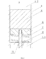
FIG.2 is a schematic diagram of partially enlarged area "A" inFIG. 1 . -
FIG.3 is a schematic diagram of partially enlarged area " B" inFIG. 1 . -
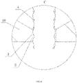
FIG.4 is a schematic diagram of partially enlarged area " C" inFIG. 3 . - The present disclosure will be explained in detail by referring to the appended drawings and the particular embodiments.
- The present disclosure provides a handheld household grinder , which comprises a
housing 1 having an accommodating cavity 1.1 and agrinding rod 2 is arranged in the accommodating cavity 1.1 of thehousing 1; the upper portion of thegrinding rod 2 penetrates through thehousing 1 until thegrinding rod 2 is partially exposed out of the accommodating cavity 1.1; a throughhole 3 is formed at the corresponding location of thehousing 1 underneath thegrinding rod 2 along the length direction; the lower portion of thegrinding rod 2 penetrates out of the accommodating cavity 1.1 via the throughhole 3 or resets into the accommodating cavity 1.1 via the throughhole 3, that is to say, thegrinding rod 2 may move along its length direction, the lower portion of thegrinding rod 2 penetrates through the throughhole 3 to the outside of the accommodating cavity 1.1, or resets and is received in the accommodating cavity 1.1 or the lower end face of thegrinding rod 2 is just accommodated in the throughhole 3; the external lateral wall, proximal to the lower portion of thegrinding rod 2 is provided with acoarse surface 4; when thegrinding rod 2 drives thecoarse surface 4 on the external lateral wall of thegrinding rod 2 to move into the throughhole 3, the clearance between thecoarse surface 4 and the internal lateral wall of the throughhole 3 forms agrinding space 5 where materials are ground. - The said through
hole 3 is provided for the lower portion of thegrinding rod 2 to freely pass through outside the housing, therefore, it can be selected from a square hole, round hole or other arbitrary shapes. Similarly, thegrinding rod 2 can be a round rod or a square rod and etc. - The said
coarse surface 4 can be a polished rod, a plurality of pits are formed in its external lateral wall by sanding and all pits constitute thecoarse surface 4. Optionally, the external lateral wall of the polished rod is cladded with a covering layer having a coarse surface. Even, the external lateral wall is coated with a granular layer. However, considering that the grinder of the present disclosure is used mostly in family kitchen, to prevent seasonings from being mixed with impurities, granular impurities dropping from the coarse surface are not allowed, in such a case, it is preferred to sanding the polished rod to form a plurality of pits, and adjacent pits have ribs therebetween. - The
above grinding space 5 refers to an annular clearance between the internal lateral wall of the throughhole 3 and the rugged external face of thecoarse surface 4. Arbitrary point in the annular clearance varies disorderly along the radial direction. - The lower end face where the
through hole 3 is located in the accommodating cavity 1.1 sinks downwards along the vertical direction to form a tapered face 1.1.1, with its small opening end mating with the throughhole 3. This mating means that the tapered face 1.1.1 is of a horn mouth shape having different diameters at two ends, the large opening end is connected with the internal lateral wall of the accommodating cavity 1.1, while the small opening end is conncctcd with the upper end of the throughhole 3, therefore, large-grained materials in the accommodating cavity 1.1 automatically gather into the throughhole 3, and finally grinding operation is completed in thegrinding space 5. - The upper portion of the
grinding rod 2 outside the accommodating cavity 1.1 is fixed with astress block 6. An external action force is applied to thestress block 6. By driving thegrinding rod 2 to reciprocate along its axial direction with thestress block 6, seasonings are continuously ground. - The
stress block 6 is detachably connected to the upper portion of thegrinding rod 2. - A
reset spring 7 is arranged between thestress block 6 and thehousing 1, with its two ends respectively abutting against thehousing 1 and thestress block 6. - A working cavity 1.2 is arranged on the
housing 1 above the accommodating cavity 1.1. The upper portion of thegrinding rod 2 extends into the working cavity 1.2; thestress block 6 and thereset spring 7 are also located in the working cavity 1.2. Anactive block 8 is arranged above thestress block 6 deviating from thegrinding rod 2, in the working cavity 1.2.The user merely needs to grasp thehousing 1 and continuously shake thehousing 1 back and forth, that is to say, inertia force of theactive block 8 is used to impact thestress block 6 so as to grind the seasonings. In such a case, the user is able to operate with one hand. - The lateral wall of the
housing 1 extends upwards along the length direction to form a groove with an upward opening. The opening of the groove is covered with anupper end cap 9. The lower end face of theupper end cap 9 and the internal surface of the groove encircle to form the working cavity 1.2. - The
housing 1 is comprised by a body with a downward opening and alower end cap 10 covering the opening of the body. The upper end face of thelower end cap 10 and the internal lateral wall of the body encircle to form the accommodating cavity 1.1; the throughhole 3 is formed in thelower end cap 10. The seasonings are conveniently filled in the accommodating cavity 1.1 by the detachablelower end cap 10. - The accommodating cavity 1.1 is internally provided with an annular insulated
pad 11, which sheathes outside thegrinding rod 2, and of which the upper end face fits the top face of the accommodating cavity 1.1. Thegrinding rod 2 and theinsulated pad 11 are in sliding fit for preventing seasoning powder in the accommodating cavity 1.1 from blocking the part between thegrinding rod 2 and the hole in thehousing 1. - The grinder provided by the present disclosure operates as the following work principle: the user grasps the
housing 1 and shakes it back and forth along the length direction of thehousing 1, in turns, theactive block 8 in the working cavity 1.2 continuously impacts thestress block 6 under the effect of inertia force per se, the stress block drives the grindingrod 2 to reciprocate axially, such that coarse-grained seasonings are continuously brought into the grindingspace 5 following the axial movement of the grinding rod, and finally ground into fine-grained seasonings and brought out of thehousing 1. If new coarse-grained seasonings need to be refilled, one merely needs to open thelower end cap 10. - The above is merely the explanations of preferred embodiments of the present disclosure, which however cannot be understood as limitations to the claims.
Claims (5)
- A handheld household grinder, comprising a housing (1) having an accommodating cavity (1.1), whereina grinding rod (2) is arranged in the accommodating cavity (1.1) of the housing (1); the upper portion of the grinding rod (2) penetrates through the housing (1) until the grinding rod (2) is partially exposed out of the accommodating cavity (1.1);a stress block (6) is fixed on the upper portion of the grinding rod (2) outside the accommodating cavity (1.1);a through hole (3) is formed at the corresponding location of the housing (1) underneath the grinding rod (2) along the length direction; the lower portion of the grinding rod (2) penetrates out of the accommodating cavity (1.1) via the through hole (3) or resets into the accommodating cavity (1.1) via the through hole (3);a coarse surface (4) is formed on the external lateral wall and proximal to the lower portion of the grinding rod (2); when the grinding rod (2) drives the coarse surface (4) on the external lateral wall of the grinding rod (2) to move into the through hole (3), the clearance between the coarse surface (4) and the internal lateral wall of the through hole (3) forms a grinding space (5) for the materials to be ground;wherein a reset spring (7) is arranged between the stress block (6) and the housing (1), and the two ends of the reset spring (7) abut against the housing (1) and the stress block (6) respectively;characterized in thata working cavity (1.2) is arranged on the housing (1) above the accommodating cavity (1.1); the upper portion of the grinding rod (2) extends into the working cavity (1.2); the stress block (6) and the reset spring (7) are also located in the working cavity (1.2); an active block (8) is arranged above the stress block (6) in the working cavity (1.2) deviating from the grinding rod (2), wherein the inertia force of the active block (8) is used to impact the stress block (6) so as to grind the seasonings, when the user continuously shake the housing (1) back and forth.
- The handheld household grinder of claim 1, wherein the lower end face where the through hole (3) is located in the accommodating cavity (1.1) sinks downwards along the vertical direction to form a tapered face (1.1.1), the small opening end of the tapered face (1.1.1) mates with the through hole (3).
- The handheld household grinder of claim 1, wherein the stress block (6) is detachably connected to the upper portion of the grinding rod (2).
- The handheld household grinder of claim 1, wherein the lateral wall of the housing (1) extends upwards along the length direction to form a groove with an upward opening; the opening of the groove is covered with an upper end cap (9); the lower end face of the upper end cap (9) and the internal surface of the groove encircle to form the working cavity (1.2).
- The handheld household grinder of claim 1, wherein the housing (1) comprises a body with a downward opening and a lower end cap (10) covering the opening of the body; the upper end face of the lower end cap (10) and the internal lateral wall of the body encircle to form the accommodating cavity (1.1); the through hole (3) is formed in the lower end cap (10).
Applications Claiming Priority (2)
| Application Number | Priority Date | Filing Date | Title |
|---|---|---|---|
| CN201710212307.1A CN106983390B (en) | 2017-04-01 | 2017-04-01 | Handheld household grinder |
| PCT/CN2018/079053 WO2018177122A1 (en) | 2017-04-01 | 2018-03-14 | Handheld household grinder |
Publications (3)
| Publication Number | Publication Date |
|---|---|
| EP3607861A1 EP3607861A1 (en) | 2020-02-12 |
| EP3607861A4 EP3607861A4 (en) | 2020-11-11 |
| EP3607861B1 true EP3607861B1 (en) | 2022-12-21 |
Family
ID=59415030
Family Applications (1)
| Application Number | Title | Priority Date | Filing Date |
|---|---|---|---|
| EP18776199.4A Active EP3607861B1 (en) | 2017-04-01 | 2018-03-14 | Handheld household grinder |
Country Status (5)
| Country | Link |
|---|---|
| US (1) | US20200022533A1 (en) |
| EP (1) | EP3607861B1 (en) |
| JP (1) | JP3225975U (en) |
| CN (1) | CN106983390B (en) |
| WO (1) | WO2018177122A1 (en) |
Families Citing this family (7)
| Publication number | Priority date | Publication date | Assignee | Title |
|---|---|---|---|---|
| CN106983390B (en) * | 2017-04-01 | 2023-08-11 | 宁波厨聚厨房科技有限公司 | Handheld household grinder |
| TWI642397B (en) * | 2017-08-31 | 2018-12-01 | 林萱 | Seasoning grinder |
| CN114073425B (en) * | 2020-08-18 | 2024-04-19 | 宁波厨聚厨房科技有限公司 | Portable grinder |
| USD1074332S1 (en) | 2021-10-15 | 2025-05-13 | Dynavap, LLC | Grinder and fidget device |
| USD1062399S1 (en) | 2021-10-15 | 2025-02-18 | Dynavap, LLC | Grinder and fidget device |
| USD1073416S1 (en) | 2021-10-15 | 2025-05-06 | Dynavap, LLC | Grinder and fidget device |
| IT202300006561A1 (en) * | 2023-04-03 | 2024-10-03 | Giudice Giuseppe Del | SEMI-AUTOMATIC DEVICE FOR CHOPPING HERBS AND SIMILAR PRODUCTS |
Family Cites Families (20)
| Publication number | Priority date | Publication date | Assignee | Title |
|---|---|---|---|---|
| TW595375U (en) * | 2000-09-30 | 2004-06-21 | Shou-Wen Chen | Pepper grinder |
| DE20018675U1 (en) * | 2000-11-02 | 2000-12-28 | Chen, Wen-Shou, Tainan | Pepper mill |
| US6676052B2 (en) * | 2001-09-10 | 2004-01-13 | Yienn Lih Enterprise Co., Ltd. | Pepper grinding tool with a sideways lever operated with one hand |
| DE10158987B4 (en) * | 2001-11-30 | 2011-08-11 | Grützke, Joachim, N.C. | spice dispenser |
| CN2512359Y (en) * | 2001-12-05 | 2002-09-25 | 东莞良佳五金塑胶制品有限公司 | Simple pepper grinder |
| CN2657553Y (en) * | 2003-09-03 | 2004-11-24 | 何佩珍 | Mill for solid seasoning |
| CN2662802Y (en) * | 2003-10-17 | 2004-12-15 | 李伟 | Simplified grinder |
| TWM266858U (en) * | 2004-10-13 | 2005-06-11 | Chung-Jen Pai | Mill set |
| US20090078807A1 (en) * | 2007-09-21 | 2009-03-26 | Yu Wing Tang | Adjustable grinder |
| CN201481160U (en) * | 2009-09-03 | 2010-05-26 | 王松彪 | Pepper grinder with charging function |
| GB2490155B (en) * | 2011-04-20 | 2015-02-25 | Maxpat Trading & Marketing | Grater for single-handed operation |
| TW201515620A (en) * | 2013-10-22 | 2015-05-01 | zhi-rong Zheng | Condiment grinding method and grinding pot |
| CN203693394U (en) * | 2014-01-22 | 2014-07-09 | 金德全有限公司 | Portable coffee grinder |
| CN204008247U (en) * | 2014-07-24 | 2014-12-10 | 贵州省烟草公司黔南州公司 | The quick mill of a kind of Tissues of Tobacco |
| CN204722895U (en) * | 2015-04-27 | 2015-10-28 | 宁波厨聚厨房科技有限公司 | A kind of nut mill |
| CN204765209U (en) * | 2015-06-25 | 2015-11-18 | 中山市技师学院 | Household seasoning grinder |
| TW201705886A (en) * | 2015-08-07 | 2017-02-16 | 張志成 | Grinding system and grinding method |
| DE202015008815U1 (en) * | 2015-12-23 | 2016-01-19 | Joma Kunststofftechnik Gmbh & Co. Kg | Container for holding spices |
| CN106983390B (en) * | 2017-04-01 | 2023-08-11 | 宁波厨聚厨房科技有限公司 | Handheld household grinder |
| CN207101157U (en) * | 2017-04-01 | 2018-03-16 | 宁波厨聚厨房科技有限公司 | A kind of hand-held family expenses mill |
-
2017
- 2017-04-01 CN CN201710212307.1A patent/CN106983390B/en active Active
-
2018
- 2018-03-14 EP EP18776199.4A patent/EP3607861B1/en active Active
- 2018-03-14 JP JP2020600011U patent/JP3225975U/en not_active Expired - Fee Related
- 2018-03-14 WO PCT/CN2018/079053 patent/WO2018177122A1/en not_active Ceased
-
2019
- 2019-09-27 US US16/585,476 patent/US20200022533A1/en not_active Abandoned
Also Published As
| Publication number | Publication date |
|---|---|
| WO2018177122A1 (en) | 2018-10-04 |
| EP3607861A4 (en) | 2020-11-11 |
| EP3607861A1 (en) | 2020-02-12 |
| CN106983390B (en) | 2023-08-11 |
| US20200022533A1 (en) | 2020-01-23 |
| CN106983390A (en) | 2017-07-28 |
| JP3225975U (en) | 2020-04-16 |
Similar Documents
| Publication | Publication Date | Title |
|---|---|---|
| EP3607861A1 (en) | Handheld household grinder | |
| EP2596730B1 (en) | Grinder facilitating adjustment of grinding fineness | |
| CN205799114U (en) | On a kind of mobile phone faceplate, blind hole processing clears off machine | |
| CN105030086B (en) | Mill beans hand is made coffee cup | |
| CN109330340A (en) | Top energization juice extractor | |
| KR20110094531A (en) | Hand grinder with elastic dust hood | |
| US2407808A (en) | Pepper mill | |
| CN204995263U (en) | Grind beans hand cup of making coffee | |
| TWI361675B (en) | ||
| CN203446991U (en) | Novel teapot with rotary filter screen structure | |
| CN104382506A (en) | Pepper grinder | |
| KR101981190B1 (en) | Rice washing apparatus | |
| CN109158660A (en) | A kind of Multifunctional hand-held electric drill being conveniently replaceable drill bit | |
| TWM584162U (en) | Hand-held household grinder | |
| CN210548298U (en) | Drill bit cleaning device for drilling machine for machining forge piece | |
| CN203676947U (en) | Soap smashing device | |
| CN210097883U (en) | Medicinal material grinding device | |
| CN204541564U (en) | Rotary filter screen teapot | |
| CN207101157U (en) | A kind of hand-held family expenses mill | |
| CN107752802A (en) | Grinding device | |
| CN110384404B (en) | Cup with grinding function | |
| CN208973529U (en) | A kind of dismembyator | |
| JP2016007665A (en) | Grinder | |
| CN203328557U (en) | Improved structure of the grinder | |
| CN214905828U (en) | Juicer with anti-swing part |
Legal Events
| Date | Code | Title | Description |
|---|---|---|---|
| STAA | Information on the status of an ep patent application or granted ep patent |
Free format text: STATUS: THE INTERNATIONAL PUBLICATION HAS BEEN MADE |
|
| PUAI | Public reference made under article 153(3) epc to a published international application that has entered the european phase |
Free format text: ORIGINAL CODE: 0009012 |
|
| STAA | Information on the status of an ep patent application or granted ep patent |
Free format text: STATUS: REQUEST FOR EXAMINATION WAS MADE |
|
| 17P | Request for examination filed |
Effective date: 20191029 |
|
| AK | Designated contracting states |
Kind code of ref document: A1 Designated state(s): AL AT BE BG CH CY CZ DE DK EE ES FI FR GB GR HR HU IE IS IT LI LT LU LV MC MK MT NL NO PL PT RO RS SE SI SK SM TR |
|
| AX | Request for extension of the european patent |
Extension state: BA ME |
|
| DAV | Request for validation of the european patent (deleted) | ||
| DAX | Request for extension of the european patent (deleted) | ||
| A4 | Supplementary search report drawn up and despatched |
Effective date: 20201013 |
|
| RIC1 | Information provided on ipc code assigned before grant |
Ipc: A47J 42/38 20060101ALI20201007BHEP Ipc: A47J 42/34 20060101AFI20201007BHEP |
|
| GRAP | Despatch of communication of intention to grant a patent |
Free format text: ORIGINAL CODE: EPIDOSNIGR1 |
|
| STAA | Information on the status of an ep patent application or granted ep patent |
Free format text: STATUS: GRANT OF PATENT IS INTENDED |
|
| GRAS | Grant fee paid |
Free format text: ORIGINAL CODE: EPIDOSNIGR3 |
|
| INTG | Intention to grant announced |
Effective date: 20221019 |
|
| GRAA | (expected) grant |
Free format text: ORIGINAL CODE: 0009210 |
|
| STAA | Information on the status of an ep patent application or granted ep patent |
Free format text: STATUS: THE PATENT HAS BEEN GRANTED |
|
| AK | Designated contracting states |
Kind code of ref document: B1 Designated state(s): AL AT BE BG CH CY CZ DE DK EE ES FI FR GB GR HR HU IE IS IT LI LT LU LV MC MK MT NL NO PL PT RO RS SE SI SK SM TR |
|
| REG | Reference to a national code |
Ref country code: GB Ref legal event code: FG4D |
|
| REG | Reference to a national code |
Ref country code: CH Ref legal event code: EP |
|
| REG | Reference to a national code |
Ref country code: DE Ref legal event code: R096 Ref document number: 602018044535 Country of ref document: DE |
|
| REG | Reference to a national code |
Ref country code: AT Ref legal event code: REF Ref document number: 1538511 Country of ref document: AT Kind code of ref document: T Effective date: 20230115 |
|
| REG | Reference to a national code |
Ref country code: IE Ref legal event code: FG4D |
|
| REG | Reference to a national code |
Ref country code: LT Ref legal event code: MG9D |
|
| REG | Reference to a national code |
Ref country code: NL Ref legal event code: MP Effective date: 20221221 |
|
| PG25 | Lapsed in a contracting state [announced via postgrant information from national office to epo] |
Ref country code: SE Free format text: LAPSE BECAUSE OF FAILURE TO SUBMIT A TRANSLATION OF THE DESCRIPTION OR TO PAY THE FEE WITHIN THE PRESCRIBED TIME-LIMIT Effective date: 20221221 Ref country code: NO Free format text: LAPSE BECAUSE OF FAILURE TO SUBMIT A TRANSLATION OF THE DESCRIPTION OR TO PAY THE FEE WITHIN THE PRESCRIBED TIME-LIMIT Effective date: 20230321 Ref country code: LT Free format text: LAPSE BECAUSE OF FAILURE TO SUBMIT A TRANSLATION OF THE DESCRIPTION OR TO PAY THE FEE WITHIN THE PRESCRIBED TIME-LIMIT Effective date: 20221221 Ref country code: FI Free format text: LAPSE BECAUSE OF FAILURE TO SUBMIT A TRANSLATION OF THE DESCRIPTION OR TO PAY THE FEE WITHIN THE PRESCRIBED TIME-LIMIT Effective date: 20221221 |
|
| PGFP | Annual fee paid to national office [announced via postgrant information from national office to epo] |
Ref country code: FR Payment date: 20230320 Year of fee payment: 6 |
|
| REG | Reference to a national code |
Ref country code: AT Ref legal event code: MK05 Ref document number: 1538511 Country of ref document: AT Kind code of ref document: T Effective date: 20221221 |
|
| PG25 | Lapsed in a contracting state [announced via postgrant information from national office to epo] |
Ref country code: RS Free format text: LAPSE BECAUSE OF FAILURE TO SUBMIT A TRANSLATION OF THE DESCRIPTION OR TO PAY THE FEE WITHIN THE PRESCRIBED TIME-LIMIT Effective date: 20221221 Ref country code: LV Free format text: LAPSE BECAUSE OF FAILURE TO SUBMIT A TRANSLATION OF THE DESCRIPTION OR TO PAY THE FEE WITHIN THE PRESCRIBED TIME-LIMIT Effective date: 20221221 Ref country code: HR Free format text: LAPSE BECAUSE OF FAILURE TO SUBMIT A TRANSLATION OF THE DESCRIPTION OR TO PAY THE FEE WITHIN THE PRESCRIBED TIME-LIMIT Effective date: 20221221 Ref country code: GR Free format text: LAPSE BECAUSE OF FAILURE TO SUBMIT A TRANSLATION OF THE DESCRIPTION OR TO PAY THE FEE WITHIN THE PRESCRIBED TIME-LIMIT Effective date: 20230322 |
|
| PGFP | Annual fee paid to national office [announced via postgrant information from national office to epo] |
Ref country code: GB Payment date: 20230324 Year of fee payment: 6 Ref country code: DE Payment date: 20230307 Year of fee payment: 6 |
|
| PG25 | Lapsed in a contracting state [announced via postgrant information from national office to epo] |
Ref country code: NL Free format text: LAPSE BECAUSE OF FAILURE TO SUBMIT A TRANSLATION OF THE DESCRIPTION OR TO PAY THE FEE WITHIN THE PRESCRIBED TIME-LIMIT Effective date: 20221221 |
|
| PG25 | Lapsed in a contracting state [announced via postgrant information from national office to epo] |
Ref country code: SM Free format text: LAPSE BECAUSE OF FAILURE TO SUBMIT A TRANSLATION OF THE DESCRIPTION OR TO PAY THE FEE WITHIN THE PRESCRIBED TIME-LIMIT Effective date: 20221221 Ref country code: RO Free format text: LAPSE BECAUSE OF FAILURE TO SUBMIT A TRANSLATION OF THE DESCRIPTION OR TO PAY THE FEE WITHIN THE PRESCRIBED TIME-LIMIT Effective date: 20221221 Ref country code: PT Free format text: LAPSE BECAUSE OF FAILURE TO SUBMIT A TRANSLATION OF THE DESCRIPTION OR TO PAY THE FEE WITHIN THE PRESCRIBED TIME-LIMIT Effective date: 20230421 Ref country code: ES Free format text: LAPSE BECAUSE OF FAILURE TO SUBMIT A TRANSLATION OF THE DESCRIPTION OR TO PAY THE FEE WITHIN THE PRESCRIBED TIME-LIMIT Effective date: 20221221 Ref country code: EE Free format text: LAPSE BECAUSE OF FAILURE TO SUBMIT A TRANSLATION OF THE DESCRIPTION OR TO PAY THE FEE WITHIN THE PRESCRIBED TIME-LIMIT Effective date: 20221221 Ref country code: CZ Free format text: LAPSE BECAUSE OF FAILURE TO SUBMIT A TRANSLATION OF THE DESCRIPTION OR TO PAY THE FEE WITHIN THE PRESCRIBED TIME-LIMIT Effective date: 20221221 Ref country code: AT Free format text: LAPSE BECAUSE OF FAILURE TO SUBMIT A TRANSLATION OF THE DESCRIPTION OR TO PAY THE FEE WITHIN THE PRESCRIBED TIME-LIMIT Effective date: 20221221 |
|
| PG25 | Lapsed in a contracting state [announced via postgrant information from national office to epo] |
Ref country code: SK Free format text: LAPSE BECAUSE OF FAILURE TO SUBMIT A TRANSLATION OF THE DESCRIPTION OR TO PAY THE FEE WITHIN THE PRESCRIBED TIME-LIMIT Effective date: 20221221 Ref country code: PL Free format text: LAPSE BECAUSE OF FAILURE TO SUBMIT A TRANSLATION OF THE DESCRIPTION OR TO PAY THE FEE WITHIN THE PRESCRIBED TIME-LIMIT Effective date: 20221221 Ref country code: IS Free format text: LAPSE BECAUSE OF FAILURE TO SUBMIT A TRANSLATION OF THE DESCRIPTION OR TO PAY THE FEE WITHIN THE PRESCRIBED TIME-LIMIT Effective date: 20230421 Ref country code: AL Free format text: LAPSE BECAUSE OF FAILURE TO SUBMIT A TRANSLATION OF THE DESCRIPTION OR TO PAY THE FEE WITHIN THE PRESCRIBED TIME-LIMIT Effective date: 20221221 |
|
| REG | Reference to a national code |
Ref country code: DE Ref legal event code: R097 Ref document number: 602018044535 Country of ref document: DE |
|
| PLBE | No opposition filed within time limit |
Free format text: ORIGINAL CODE: 0009261 |
|
| STAA | Information on the status of an ep patent application or granted ep patent |
Free format text: STATUS: NO OPPOSITION FILED WITHIN TIME LIMIT |
|
| PG25 | Lapsed in a contracting state [announced via postgrant information from national office to epo] |
Ref country code: MC Free format text: LAPSE BECAUSE OF FAILURE TO SUBMIT A TRANSLATION OF THE DESCRIPTION OR TO PAY THE FEE WITHIN THE PRESCRIBED TIME-LIMIT Effective date: 20221221 Ref country code: DK Free format text: LAPSE BECAUSE OF FAILURE TO SUBMIT A TRANSLATION OF THE DESCRIPTION OR TO PAY THE FEE WITHIN THE PRESCRIBED TIME-LIMIT Effective date: 20221221 |
|
| REG | Reference to a national code |
Ref country code: CH Ref legal event code: PL |
|
| 26N | No opposition filed |
Effective date: 20230922 |
|
| REG | Reference to a national code |
Ref country code: BE Ref legal event code: MM Effective date: 20230331 |
|
| PG25 | Lapsed in a contracting state [announced via postgrant information from national office to epo] |
Ref country code: LU Free format text: LAPSE BECAUSE OF NON-PAYMENT OF DUE FEES Effective date: 20230314 |
|
| REG | Reference to a national code |
Ref country code: IE Ref legal event code: MM4A |
|
| PG25 | Lapsed in a contracting state [announced via postgrant information from national office to epo] |
Ref country code: SI Free format text: LAPSE BECAUSE OF FAILURE TO SUBMIT A TRANSLATION OF THE DESCRIPTION OR TO PAY THE FEE WITHIN THE PRESCRIBED TIME-LIMIT Effective date: 20221221 Ref country code: LI Free format text: LAPSE BECAUSE OF NON-PAYMENT OF DUE FEES Effective date: 20230331 Ref country code: IE Free format text: LAPSE BECAUSE OF NON-PAYMENT OF DUE FEES Effective date: 20230314 Ref country code: CH Free format text: LAPSE BECAUSE OF NON-PAYMENT OF DUE FEES Effective date: 20230331 |
|
| PG25 | Lapsed in a contracting state [announced via postgrant information from national office to epo] |
Ref country code: BE Free format text: LAPSE BECAUSE OF NON-PAYMENT OF DUE FEES Effective date: 20230331 |
|
| PG25 | Lapsed in a contracting state [announced via postgrant information from national office to epo] |
Ref country code: IT Free format text: LAPSE BECAUSE OF FAILURE TO SUBMIT A TRANSLATION OF THE DESCRIPTION OR TO PAY THE FEE WITHIN THE PRESCRIBED TIME-LIMIT Effective date: 20221221 |
|
| REG | Reference to a national code |
Ref country code: DE Ref legal event code: R119 Ref document number: 602018044535 Country of ref document: DE |
|
| PG25 | Lapsed in a contracting state [announced via postgrant information from national office to epo] |
Ref country code: BG Free format text: LAPSE BECAUSE OF FAILURE TO SUBMIT A TRANSLATION OF THE DESCRIPTION OR TO PAY THE FEE WITHIN THE PRESCRIBED TIME-LIMIT Effective date: 20221221 |
|
| GBPC | Gb: european patent ceased through non-payment of renewal fee |
Effective date: 20240314 |
|
| PG25 | Lapsed in a contracting state [announced via postgrant information from national office to epo] |
Ref country code: BG Free format text: LAPSE BECAUSE OF FAILURE TO SUBMIT A TRANSLATION OF THE DESCRIPTION OR TO PAY THE FEE WITHIN THE PRESCRIBED TIME-LIMIT Effective date: 20221221 |
|
| PG25 | Lapsed in a contracting state [announced via postgrant information from national office to epo] |
Ref country code: DE Free format text: LAPSE BECAUSE OF NON-PAYMENT OF DUE FEES Effective date: 20241001 |
|
| PG25 | Lapsed in a contracting state [announced via postgrant information from national office to epo] |
Ref country code: GB Free format text: LAPSE BECAUSE OF NON-PAYMENT OF DUE FEES Effective date: 20240314 |
|
| PG25 | Lapsed in a contracting state [announced via postgrant information from national office to epo] |
Ref country code: FR Free format text: LAPSE BECAUSE OF NON-PAYMENT OF DUE FEES Effective date: 20240331 |
|
| PG25 | Lapsed in a contracting state [announced via postgrant information from national office to epo] |
Ref country code: GB Free format text: LAPSE BECAUSE OF NON-PAYMENT OF DUE FEES Effective date: 20240314 Ref country code: FR Free format text: LAPSE BECAUSE OF NON-PAYMENT OF DUE FEES Effective date: 20240331 Ref country code: DE Free format text: LAPSE BECAUSE OF NON-PAYMENT OF DUE FEES Effective date: 20241001 |
|
| PG25 | Lapsed in a contracting state [announced via postgrant information from national office to epo] |
Ref country code: CY Free format text: LAPSE BECAUSE OF FAILURE TO SUBMIT A TRANSLATION OF THE DESCRIPTION OR TO PAY THE FEE WITHIN THE PRESCRIBED TIME-LIMIT; INVALID AB INITIO Effective date: 20180314 |
|
| PG25 | Lapsed in a contracting state [announced via postgrant information from national office to epo] |
Ref country code: HU Free format text: LAPSE BECAUSE OF FAILURE TO SUBMIT A TRANSLATION OF THE DESCRIPTION OR TO PAY THE FEE WITHIN THE PRESCRIBED TIME-LIMIT; INVALID AB INITIO Effective date: 20180314 |
|
| PG25 | Lapsed in a contracting state [announced via postgrant information from national office to epo] |
Ref country code: TR Free format text: LAPSE BECAUSE OF FAILURE TO SUBMIT A TRANSLATION OF THE DESCRIPTION OR TO PAY THE FEE WITHIN THE PRESCRIBED TIME-LIMIT Effective date: 20221221 |