EP3607848A1 - Clamping system - Google Patents
Clamping system Download PDFInfo
- Publication number
- EP3607848A1 EP3607848A1 EP19189821.2A EP19189821A EP3607848A1 EP 3607848 A1 EP3607848 A1 EP 3607848A1 EP 19189821 A EP19189821 A EP 19189821A EP 3607848 A1 EP3607848 A1 EP 3607848A1
- Authority
- EP
- European Patent Office
- Prior art keywords
- bracket
- path
- clamping system
- angle
- component
- Prior art date
- Legal status (The legal status is an assumption and is not a legal conclusion. Google has not performed a legal analysis and makes no representation as to the accuracy of the status listed.)
- Withdrawn
Links
Images





Classifications
-
- A—HUMAN NECESSITIES
- A43—FOOTWEAR
- A43D—MACHINES, TOOLS, EQUIPMENT OR METHODS FOR MANUFACTURING OR REPAIRING FOOTWEAR
- A43D25/00—Devices for gluing shoe parts
- A43D25/047—Devices for lasting with adhesives or for gluing together insoles and uppers
-
- F—MECHANICAL ENGINEERING; LIGHTING; HEATING; WEAPONS; BLASTING
- F16—ENGINEERING ELEMENTS AND UNITS; GENERAL MEASURES FOR PRODUCING AND MAINTAINING EFFECTIVE FUNCTIONING OF MACHINES OR INSTALLATIONS; THERMAL INSULATION IN GENERAL
- F16M—FRAMES, CASINGS OR BEDS OF ENGINES, MACHINES OR APPARATUS, NOT SPECIFIC TO ENGINES, MACHINES OR APPARATUS PROVIDED FOR ELSEWHERE; STANDS; SUPPORTS
- F16M11/00—Stands or trestles as supports for apparatus or articles placed thereon ; Stands for scientific apparatus such as gravitational force meters
- F16M11/02—Heads
- F16M11/04—Means for attachment of apparatus; Means allowing adjustment of the apparatus relatively to the stand
- F16M11/06—Means for attachment of apparatus; Means allowing adjustment of the apparatus relatively to the stand allowing pivoting
- F16M11/08—Means for attachment of apparatus; Means allowing adjustment of the apparatus relatively to the stand allowing pivoting around a vertical axis, e.g. panoramic heads
-
- A—HUMAN NECESSITIES
- A43—FOOTWEAR
- A43D—MACHINES, TOOLS, EQUIPMENT OR METHODS FOR MANUFACTURING OR REPAIRING FOOTWEAR
- A43D25/00—Devices for gluing shoe parts
-
- A—HUMAN NECESSITIES
- A43—FOOTWEAR
- A43D—MACHINES, TOOLS, EQUIPMENT OR METHODS FOR MANUFACTURING OR REPAIRING FOOTWEAR
- A43D86/00—Machines for assembling soles or heels onto uppers, not provided for in groups A43D25/00 - A43D83/00, e.g. by welding
-
- B—PERFORMING OPERATIONS; TRANSPORTING
- B23—MACHINE TOOLS; METAL-WORKING NOT OTHERWISE PROVIDED FOR
- B23B—TURNING; BORING
- B23B31/00—Chucks; Expansion mandrels; Adaptations thereof for remote control
- B23B31/02—Chucks
- B23B31/10—Chucks characterised by the retaining or gripping devices or their immediate operating means
- B23B31/12—Chucks with simultaneously-acting jaws, whether or not also individually adjustable
- B23B31/16—Chucks with simultaneously-acting jaws, whether or not also individually adjustable moving radially
- B23B31/16004—Jaws movement actuated by one or more spiral grooves
-
- B—PERFORMING OPERATIONS; TRANSPORTING
- B23—MACHINE TOOLS; METAL-WORKING NOT OTHERWISE PROVIDED FOR
- B23Q—DETAILS, COMPONENTS, OR ACCESSORIES FOR MACHINE TOOLS, e.g. ARRANGEMENTS FOR COPYING OR CONTROLLING; MACHINE TOOLS IN GENERAL CHARACTERISED BY THE CONSTRUCTION OF PARTICULAR DETAILS OR COMPONENTS; COMBINATIONS OR ASSOCIATIONS OF METAL-WORKING MACHINES, NOT DIRECTED TO A PARTICULAR RESULT
- B23Q3/00—Devices holding, supporting, or positioning work or tools, of a kind normally removable from the machine
-
- B—PERFORMING OPERATIONS; TRANSPORTING
- B25—HAND TOOLS; PORTABLE POWER-DRIVEN TOOLS; MANIPULATORS
- B25B—TOOLS OR BENCH DEVICES NOT OTHERWISE PROVIDED FOR, FOR FASTENING, CONNECTING, DISENGAGING, OR HOLDING
- B25B1/00—Vices
- B25B1/24—Details, e.g. jaws of special shape, slideways
- B25B1/2405—Construction of the jaws
- B25B1/241—Construction of the jaws characterised by surface features or material
- B25B1/2415—Construction of the jaws characterised by surface features or material being composed of a plurality of parts adapting to the shape of the workpiece
- B25B1/2421—Construction of the jaws characterised by surface features or material being composed of a plurality of parts adapting to the shape of the workpiece the parts having a linear movement
-
- B—PERFORMING OPERATIONS; TRANSPORTING
- B25—HAND TOOLS; PORTABLE POWER-DRIVEN TOOLS; MANIPULATORS
- B25B—TOOLS OR BENCH DEVICES NOT OTHERWISE PROVIDED FOR, FOR FASTENING, CONNECTING, DISENGAGING, OR HOLDING
- B25B11/00—Work holders not covered by any preceding group in the subclass, e.g. magnetic work holders, vacuum work holders
- B25B11/02—Assembly jigs
-
- B—PERFORMING OPERATIONS; TRANSPORTING
- B25—HAND TOOLS; PORTABLE POWER-DRIVEN TOOLS; MANIPULATORS
- B25B—TOOLS OR BENCH DEVICES NOT OTHERWISE PROVIDED FOR, FOR FASTENING, CONNECTING, DISENGAGING, OR HOLDING
- B25B5/00—Clamps
- B25B5/003—Combinations of clamps
-
- B—PERFORMING OPERATIONS; TRANSPORTING
- B25—HAND TOOLS; PORTABLE POWER-DRIVEN TOOLS; MANIPULATORS
- B25B—TOOLS OR BENCH DEVICES NOT OTHERWISE PROVIDED FOR, FOR FASTENING, CONNECTING, DISENGAGING, OR HOLDING
- B25B5/00—Clamps
- B25B5/006—Supporting devices for clamps
-
- B—PERFORMING OPERATIONS; TRANSPORTING
- B25—HAND TOOLS; PORTABLE POWER-DRIVEN TOOLS; MANIPULATORS
- B25B—TOOLS OR BENCH DEVICES NOT OTHERWISE PROVIDED FOR, FOR FASTENING, CONNECTING, DISENGAGING, OR HOLDING
- B25B5/00—Clamps
- B25B5/06—Arrangements for positively actuating jaws
- B25B5/08—Arrangements for positively actuating jaws using cams
Definitions
- the present invention relates to an improved clamping system, especially for the production of an article of footwear or a sports article.
- Numerous clamping systems are known for temporarily fixing workpieces during assembly. It is frequently required in a production environment to secure workpieces of different sizes for a particular process. In order to allow an accurate and secure arrangement of a workpiece it is presently required to use a number of custom-fitted forms or molds. This is especially true for fragile and / or soft workpieces which cannot be clamped with great force without risking damage to the workpiece.
- an issue in the production of footwear concerns the securing of a midsole during assembly.
- Present methods involve a number of forms that are fitted specifically for one particular type, size, and side (left/right) of midsole. This leads to a large inventory and lost processing time due to tooling change over.
- DE 20 2012 004 576 U1 concerns a workpiece carrier for use, for example, on a workpiece conveyor with its own base pallet, on which the workpiece carrier can be mounted in order to bring the workpieces into the engine room.
- An object underlying the present invention is therefore to provide an improved clamping system and method that allows even fragile workpieces of different sizes, shapes, and types to be secured during processing in a simple and effective manner.
- a clamping system for a component for an article of footwear or a sports article, comprising: (a) a first member; (b) a second member, (c) wherein the first member and the second member are rotatable relative to each other about a pivot; (d) a first bracket, wherein the first bracket is adapted to slidably move along a first path on the first member and a second path, by a first distance, on the second member, when the first member and the second member are rotated relative to each other from a first angle to a second angle; and (e) at least a second bracket, wherein the second bracket is adapted to slidably move along a third path on the first member and a fourth path, by a second distance, on the second member, when the first member and the second member are rotated relative to each other from the first angle to the second angle.
- An article of footwear may be a shoe, a boot, a hiking boot, a running shoe, a football boot, a tennis shoe, a golf shoe, sandal, etc.
- a sports article may be any type of apparel especially used for sports, or any sports accessory, such as for example, a tennis racket, a baseball bat, a shinguard, a glove, a knee or elbow protector etc.
- a path is understood as a physical path, rather than a potentially mathematically infinite path, a section of which would be the physical path.
- a member is understood as any solid construction, that may consist of just a single piece or may comprise several pieces, which are preferably connected.
- the member may be essentially rigid, wherein "essentially rigid” means not necessarily rigid in a strictly mathematical sense but allowing for some flexibility inherent to real materials, such as a metal, e.g. aluminium, steel etc., wood, polymers, e.g. acrylonitrile butadiene styrene copolymer (also known as ABS), poly(methyl methacrylate), a polycarbonate etc.
- the surfaces of each of the members may or may not be flat.
- a bracket is understood to be any moveable item configured for securing the component by contacting and engaging the component. It is to be understood that the clamping system may comprise further brackets, for example a third bracket, a fourth bracket, a fifth bracket etc.
- the clamping system allows the relative motion of the first bracket and the second bracket to be controlled with a single operation, i.e. the relative rotation of the first member and the second member. Therefore, the system is easy and fast to operate and may be adapted to different sizes of components simply by rotating the first member relative to the second member. It is to be understood that it is not important which member is physically rotated with respect to an external reference frame, such as a workbench. It is only important that a relative rotation of the first member and the second member is performed.
- a key aspect of the present invention is thus that the first distance and the second distance by which the first and bracket move, respectively, is determined by the first and second angle.
- a single parameter, the relative angle of the first and second member controls the motion of the first bracket, the second bracket, and further brackets, if present.
- the first angle and the second angle are defined with respect to one, i.e. the same, suitable axis.
- suitable axis There may be numerous suitable axes, for example the first angle and the second angle may conveniently be measured with respect to an edge of the first member or the second member.
- first angle and the second angle are not necessarily limiting angles, e.g. a minimum or a maximum physically reachable value. In other words, the clamping system may be operable beyond the first and the second angle.
- the rotation axis about which the first member and the second member rotate may be essentially perpendicular to the first member and/or the second member. However, it is also possible that the rotation axis is tilted by a tilting angle with respect to a normal to the surface of the first member and/or a normal to the surface of the second member. This way, the clamping system allows the relative motion of the first bracket and the second bracket to be controlled in three dimensions (relative to the first and / or second member and so also relative to the component).
- the tilting angle may be at least 5°, or at least 15° to allow a greater control in three dimensions.
- the pivot is located on the rotation axis. However, it is not necessary for a physical joint to be located at the pivot.
- the rotation mechanism may be located away from the pivot. For example, this may be done by an essentially-circular guiding wheel arranged at an outside of the clamping system, wherein a rotation center of the guiding wheel is located at the pivot.
- the guiding wheel may be supported from below with a circular bearing.
- the mechanism driving the motion may be on an outside of the clamping system, for example as a linear actuator acting tangentially to the ring, or with a geared interface, and / or a motor. This may provide more space for a component to be secured by the clamping system.
- any one of the first path, the second path, the third path, and the fourth path may have any shape, for example approximated by or given by any mathematical function, which may, for example, be defined by an explicit equation or a parametric equation.
- suitable functions may define a circle, an ellipse, a hyperbola, a trochoid, a cycloid, a parabola, a straight line, a sinusoid, or combinations thereof.
- the shapes of the paths determine the motion of the first bracket and the second bracket effected by the relative rotation of the first member at the second member. Therefore, the shapes may be selected such that different sizes of components are clamped effectively when engaged by the first bracket and the second bracket. Therefore, the clamping system according to the present invention allows a component to be secured effectively even without application of a large clamping force, thus preventing damage especially to a soft or fragile component.
- Any one of the first path, the second path, the third path, and the fourth path may be located on a surface of the first member or the second member, respectively.
- any one of the first path, the second path, the third path, and the fourth path may be located on an inside of the first member and/or the second member.
- This arrangement may also allow a three-dimensional control of the first bracket and the second bracket by a single operation, i.e. the relative rotation of the first member and the second member.
- the first member may comprise a first plate and the second member may comprise a second plate. This allows for a simple production of the first member and the second member and enables a great amount of choice for any one of the first path, the second path, the third path, and the fourth path, without the risk of collision between any of the paths, which is preferably avoided.
- the first path may be defined by a first slot arranged in the first member and the third path may be defined by a second slot arranged in the first member.
- a slot may be any indentation or recess that may or may not extend from a surface to an opposing surface on the first member. This allows a simple, accurate, and fast production of the first member and provides a durable first and third path.
- a slot may be drilled or milled into the first member.
- the first path may be defined by a first guide rail or a first pair of guide rails and the third path may be defined by a second guide rail or a second pair of guide rails.
- the first bracket may be attached to a first pin and / or the second bracket may be attached to a second pin, wherein the first and / or the second pin is/are arranged in the first slot or the second slot, respectively.
- a pin may have approximate rotational symmetry such as to facilitate low-friction sliding along the first and second slot.
- the first bracket may be essentially rigidly attached to a first pin and / or the second bracket may be essentially rigidly attached to a second pin.
- "Essentially rigidly attached” means not allowing for any relative motion except due to some flexibility of the material and manufacturing tolerances. This setup using a pin may be produced simply and accurately and allows for an accurate control of the first bracket and the second bracket with low wear and tear.
- the first pin and / or the second pin may further comprise means for attaching the first pin and / or the second pin to the first member such that the first pin and / or the second pin may slide along the first slot or the second slot, respectively, but cannot move out of the first slot or the second slot, respectively.
- suitable means for attaching for this purpose may be a nut tightened around a threaded pin. This way, the clamping system is more robust and may be used with a reduced need for maintenance in an industrial production environment.
- the second path may be defined by a first channel arranged in the second member and the fourth path may be defined by a second channel arranged in the second member.
- a channel may be any indentation or recess that may or may not extend from a surface to an opposing surface of the second member. This allows a simple, accurate, and fast production of the second member and provides a durable second and fourth path. For example, a channel may be drilled or milled into the second member. However, other arrangements are possible.
- the second path may be defined by a third guide rail or a third pair of guide rails and the fourth path may be defined by a fourth guide rail or a fourth pair of guide rails.
- the first bracket may be attached to a first slider and / or the second bracket may be attached to a second slider and the first and / or the second slider may be arranged in the first channel or the second channel, respectively.
- Each bracket may be attached to one slider to allow a spatially-efficient arrangement.
- the first bracket may further be attached to a third slider and / or the second bracket may further be attached to a fourth slider.
- the third and / or the fourth slider may be arranged in a third channel or a fourth channel, respectively.
- the first bracket and / or the second bracket may be attached to two sliders. This allows a more stable locking-mechanism of the first and /or second bracket and may prevent twisting and uneven bending forces.
- the third channel may be essentially parallel to the first channel and the fourth channel may be essentially parallel to the second channel.
- first bracket and / or the second bracket may be attached to further sliders.
- the first bracket may be essentially rigidly attached to a first slider (or possible further sliders such as the third slider) and / or the second bracket may be essentially rigidly attached to a second slider (or possible further sliders such as the fourth slider).
- This setup using a slider may be produced simply and accurately and allows for an accurate control of the first bracket and the second bracket with low wear and tear.
- a slider may be a protrusion similar to a pin.
- a slider may lack rotational symmetry such as to prevent rotation of the first bracket and/or the second bracket with respect to the second member.
- a non-rotationally-symmetric slider may be attached to the first bracket or the second bracket, respectively, using a rotatable attachment mechanism. The inventors have found that this may improve the stability of the clamping system.
- the first slider and / or the second slider may further comprise means for attaching the first slider and / or the second slider to the second member such that the first slider and / or the second slider may slide along the first channel or the second channel, respectively, but cannot move out of the first channel or the second channel, respectively.
- suitable means for attaching for this purpose may be a nut tightened around a threaded slider, or groves formed on the sides of the slider. This way, the clamping system is more robust and may be used with a reduced need for maintenance in an industrial production environment.
- pins, sliders, slots, or channels may comprise a durable, low friction material, e.g. polytetrafluoroethylene (PTFE), which may be applied as a surface coating or in the bulk of any of these parts.
- PTFE polytetrafluoroethylene
- the first bracket and / or the second bracket may be rotatable with respect to the first member and / or the second member.
- the first bracket and / or the second bracket may be rotatable with respect to the second member. This additional degree of freedom may allow a better grip of the first bracket and/or the second bracket of the component.
- the first bracket and / or the second bracket are not rotatable with respect to the second member. This arrangement is simpler and may be more stable.
- the clamping system engages the component when rotating the first member relative to the second member from the first angle to the second angle. It should be noted that the clamping system, in particular the first bracket and the second bracket, may already engage the component before the full range of motion of the clamping system has been exploited, i.e. before the second angle has been reached, when starting from the first angle.
- the second distance may be greater than the first distance.
- the first bracket and the second bracket may move in a non-symmetric, non-circular manner, when rotating the first member relative to the second member.
- first bracket and the second bracket may be achieved for numerous shapes of the first and third path.
- Rotation of the first member relative to the second member from the first angle to the second angle may cause the first bracket to move towards the second bracket.
- the first bracket and the second bracket may be located on opposite sides of the component. Therefore, this arrangement allows a particularly good grip on the component.
- the second path and the fourth path may be essentially linear. This arrangement may allow for a simple construction as well as a low wear and tear, e.g. on the first and second slider (or any further sliders).
- the first path may comprise a first position and a second position, wherein the first position may be located at a first-position distance from the pivot and the second position may be located at a second-position distance from the pivot, wherein first-position distance may be different from the second-position distance; and / or the third path may comprise a third position and a fourth position, wherein the third position may be located at a third-position distance from the pivot and the fourth position may be located at a fourth-position distance from the pivot, wherein the third-position distance may be different from the fourth-position distance.
- a first bracket displacement vector defining the direction and magnitude of displacement of the first bracket, comprises a radial component with respect to the pivot. The inventors have found this is especially effective in achieving a good clamping effect, since it means that the component is pushed towards or away from the pivot by the first bracket.
- a second bracket displacement vector defining the direction and magnitude of displacement of the second bracket, comprises a radial component with respect to the pivot. The inventors have found this is especially effective in achieving a good clamping effect, since it means that the component is pushed towards or away from the pivot by the second bracket.
- Clamping is particularly effective if the first-position distance is different from the second-position distance and the third-position distance is different from the fourth-position distance.
- the first bracket pushes the component radially towards or away from the pivot and the second bracket pushes the component radially towards or away from the pivot.
- the first bracket and the second bracket may, in some configurations, clamp the component between them, without the need for further structural elements to guide or hold the component.
- the displacement of the first bracket upon rotation of the first member relative to the second member from the first angle to the second angle can be determined and engineered as follows.
- the rotation of the first member relative to the second member causes a circular motion of the first member relative to the second member in the plane of rotation.
- a first position of the first bracket is defined. Physically the first position may, for example, be defined by a first position of a first pin.
- a circle centered on the pivot is drawn through the first position, thus also defining a starting position on the circle, which may be selected to coincide with the first position.
- a final position on the circle, in the reference frame of the first member is determined by the starting position, the first angle, and the second angle, wherein the first and second angle are defined by the relative orientation of the first member and the second member.
- a desired first bracket displacement vector is defined.
- the first bracket displacement vector may be arranged radially pointing away or towards the pivot.
- the first bracket displacement vector further comprises a non-radial component.
- the vector sum of the final position on the circle and the first bracket displacement vector determines the second position on the first path. Since the first and second angle are defined with respect to the relative orientation of the first member and the second member, the angle between the first position of the first bracket and the second position of the first bracket, both determined with respect to the pivot, is not identical to the difference between the first and second angle, if the first bracket displacement vector further comprises a non-radial component.
- the first bracket is constrained to slidably move at least partly along the second path. Therefore, in the simple case in which the second path is linear, the first bracket displacement vector is parallel to a second path vector, which is defined by the direction of the second path, in the reference frame of the second member. It is to be understood, that a similar method may be applied to determine the displacement of the second bracket or any additional brackets, if present, upon rotation of the first member relative to the second member from the first angle to the second angle.
- the first path may comprise a first essentially circular segment and / or the third path may comprise a second essentially circular segment.
- Essentially circular means, in this context, that the first segment and / or the second segment need not be mathematically perfect segments but may allow for manufacturing tolerances. This arrangement may allow for a simple construction and a smooth movement of the first and second bracket, therefore helping to prevent damage to the component due to a sudden movement of the first and second bracket. Moreover, it helps to ensure that the first and second bracket move at the same speed when the first member and the second member are rotated relative to each other about the pivot thus allowing an effective clamping without an undesirable movement of the component, that may be caused by clamps that move at different speeds.
- the first path may comprise a first end and a second end, wherein the first path may deviate from an essentially circular shape at the first end by a first deviation vector and / or at the second end by a second deviation vector; and / or wherein the third path may comprise a third end and a fourth end, wherein the third path may deviate from an essentially circular shape at the third end by a third deviation vector and / or at the fourth end by a fourth deviation vector.
- the center of the first essentially circular segment may be located at the pivot. Therefore, the sum of the first and the second deviation vector may yield the first distance. Additionally, or alternatively, the center of the second essentially circular segment may be located at the pivot. Therefore, the sum of the third and the fourth deviation vector may yield the second distance.
- This arrangement allows for a simple arrangement of the clamping system.
- the first segment and the second segment may not be concentric.
- the arrangement wherein the first segment and the second segment are not concentric allows a simple way of effecting a different motion of the first bracket compared to the second bracket, in order to improve the accuracy of the grip for different sizes of components as described herein.
- the first segment may have a first center and the second segment path may have a second center and the first center may be displaced by a first displacement vector from the pivot and the second center may be displaced by a second displacement vector from the pivot that is not identical to the first displacement vector.
- the second displacement vector may have a larger magnitude than the first displacement vector.
- the inventors have found that, the greater the displacement vector, the greater the motion of the respective bracket may be, that is effected by a rotation of the first member relative to the second member by a given rotation angle. Therefore, this arrangement effects a larger movement of the second bracket compared to the first bracket, thus improving the accuracy of the grip for different sizes of components as described herein.
- the first, second, third, and fourth path may be selected such as to engineer a different timing and / or speed of the first and second bracket.
- the clamping system may comprise at least three brackets and the three brackets may be arranged such as to form a convex void for receiving a convex component in at least one angular orientation of the first and second member.
- the void comprises a concave shape or a mixed concave and convex shape, i.e. a first part of the void may be convex while a second part of the void may be concave.
- Many components may have a convex shape for at least a portion of the component, for example much of a forefoot region of an article of footwear has a convex shape. Therefore, the grip is improved for components that comprise a convex shape.
- the three brackets may alternatively be arranged to create a concave void for receiving a concave component in at least one angular orientation of the first and second member.
- the component may be a sole element of an article of footwear.
- Sole elements may be fragile and / or soft and thus the clamping system according to the present invention is particularly beneficial for securing a sole element for an article of footwear, e.g. during production or repair.
- the second bracket may be configured to contact a forefoot portion of the sole element and the first bracket may be configured to contact a rearfoot portion of the sole element.
- This arrangement may be advantageous to achieve a minimum level of grip.
- the differences between different sizes of an article of footwear may be greater in a forefoot portion than in a rear foot portion. Therefore, the combination of this feature and the feature wherein the second distance may be greater than the first distance, is particularly advantageous as rotation of the first member and the second member by a given angle therefore leads to a greater attraction or advancement of the second bracket in a forefoot portion than of the first bracket in their rear foot portion.
- At least one of: the first bracket, the second bracket, the first element, or the second element may comprise a metal, e.g. aluminium, steel etc.
- a metal may generally offer a good level of durability.
- the first bracket, the second bracket, the first element, and / or the second element may comprise wood, polymers, e.g. acrylonitrile butadiene styrene copolymer (also known as ABS), poly(methyl methacrylate), a polycarbonate etc, which are also durable but more lightweight.
- the invention further concerns a method of securing a component, especially for an article of footwear or a sports article, comprising using a clamping system according to the present invention.
- a clamping system according to the present invention therefore lead to an improved method of securing a component.
- the using may comprise: (a) rotating the first plate to the first angle relative to the second plate; (b) arranging the component proximate to the first and the second bracket; and (c) rotating the first plate to the second angle relative to the second plate such that the first and / or second brackets touches the component.
- the first angle and the second angle may represent the opening and closing position of the clamping system for a particular application based, for example, on the properties of the component, especially its size and shape, and the procedure to be performed. It should be understood that any or all steps of this method may be performed automatically, for example by a computer-controlled system.
- the component may be a sole element. It was already described herein, why the clamping system according to the present invention may be particularly advantageous for securing a sole element.
- the sole element may comprise a midsole.
- a midsole is generally quite soft, especially compared with an outsole. Therefore, the present method is particularly advantageous and may help to prevent damage to a soft and fragile midsole.
- the sole element may further comprise an outsole.
- the method may further comprise attaching a portion of an upper to the midsole, when the sole element is secured in the clamping system. This is an important step in the production of footwear. It is important that the sole element is secured well during this production step, since once the portion of the sole element is secured to the upper, it may not be possible to adjust their arrangement without damaging the article of footwear.
- the attaching may comprise welding. Welding, for example infrared welding, maybe advantageous since it does not involve the use of solvents. Furthermore, a particularly secure connection may be achieved if two similar materials, for example two materials comprising a same thermoplastic polymer, are welded together.
- Figs. 1A-C show an exemplary clamping system 10 according to the present invention in different stages of operation.
- Fig. 1A shows the clamping system 10 when the first member 11 and the second member 12 are at a first angle ⁇ 14
- Fig. 1B shows the clamping system 10 when the first member 11 and the second member 12 are at an intermediate angle ⁇
- Fig. 1C shows the clamping system 10 when the first member 11 and the second member 12 are at a second angle ⁇ 16.
- the space configured to receive the component is at the bottom end of the clamping system.
- the clamping system 10 is for a component, especially for an article of footwear or a sports article and comprises: (a) a first member 11; (b) a second member 12, (c) wherein the first member 11 and the second member 12 are rotatable relative to each other about a pivot 13 from a first angle 14 to a second angle 16; (d) a first bracket 17a, wherein the first bracket 17a is adapted to slidably move along a first path 18a on the first member 11 and a second path, by a first distance, on the second member 12, when the first member 11 and the second member 12 rotate relative to each other; and (e) at least a second bracket 17b, wherein the second bracket 17b is adapted to slidably move along a third path 18b on the first member 11 and a fourth path 20b, by a second distance, on the second member 12, when the first member 11 and the second member 12 rotate relative to each other.
- the clamping system 10 comprises further brackets, in this case a total of 12 brackets.
- the clamping system 10 allows the relative motion of each of the brackets to be controlled with a single operation, i.e. the relative rotation of the first member 11 and the second member 12.
- the brackets are arranged such as to form a convex void for receiving a convex component in at least one angular orientation of the first and second member 12.
- FIG. 1A shows an "open” configuration of the clamping system 10
- Fig. 1B an intermediate configuration
- Fig. 1C shows a "closed", i.e. engaging, configuration of the clamping system 10.
- the system is easy and fast to operate and may be adapted to different sizes of components simply by rotating the first member 11 relative to the second member 12.
- the first angle 14 and the second angle 16 are defined with respect to one, i.e. the same, suitable axis. In this example, the first angle 14 and the second angle 16 are conveniently defined with respect to an edge of the first member 11 and the second member 12.
- the rotation axis about which the first member 11 and the second member 12 rotate is essentially perpendicular to the first member 11 and the second member 12.
- the rotation axis is tilted by a tilting angle with respect to a normal to the surface of the first member 11 and/or a normal to the surface of the second member 12.
- the first path 18a, the second path, the third path 18b, and the fourth path 20b are located on a surface of the first member 11 or the second member 12, respectively. However, it is also possible that any one of the first path 18a, the second path, the third path 18b, and the fourth path 20b is located on an inside of the first member 11 and/or the second member 12.
- the first member 11 comprises a first plate and the second member 12 comprises a second plate.
- the first path 18a is defined by a first slot arranged in the first member 11 and the third path 18b is defined by a second slot arranged in the first member 11.
- the first path 18a may be defined by a first guide rail or a first pair of guide rails and the third path 18b may be defined by a second guide rail or a second pair of guide rails.
- the first bracket 17a is attached to a first pin 19a and the second bracket 17b is attached to a second pin 19b, wherein the first 19a and the second pin 19b are arranged in the first slot and the second slot, respectively.
- the exemplary pins have approximate rotational symmetry such as to facilitate low-friction sliding in the first and second slot, respectively.
- the first bracket 17a is essentially rigidly attached to a first pin 19a and the second bracket 17b is essentially rigidly attached to a second pin 19b.
- neither the first pin 19a nor the second pin 19b comprises means for attaching the first pin 19a and the second pin 19b to the first member 11 such that the first pin 19a and the second pin 19b may slide along the first slot or the second slot, respectively, but cannot move out of the first slot or the second slot, respectively.
- the first pin 19a and / or the second pin 19b may comprise such means.
- the second path (not shown) is defined by a first channel (not shown) arranged in the second member 12 and the fourth path 20b (visible in Fig. 1A only) is defined by a second channel arranged in the second member 12.
- the exemplary channels are an indentation or recess that may or may not extend from a surface to an opposing surface on the second member 12.
- the second path may be defined by a third guide rail or a third pair of guide rails and the fourth path 20b may be defined by a fourth guide rail or a fourth pair of guide rails.
- the exemplary first and second brackets 17b are rotatable with respect to the first member 11 and the second member 12. This additional degree of freedom allows a better grip of the first bracket and the second bracket 17b of the component.
- the second distance may be greater than the first distance.
- the first bracket 17a and the second bracket 17b may move in a non-symmetric, non-circular manner, when rotating the first member 11 relative to the second member 12. This can be seen very well by comparing Figs. 1A-C , which shows that the second bracket 17b moves a lot more than the first bracket 17a.
- An important insight of the inventors was that many components have an irregular shape. Therefore, the differences between different sizes of a component may be greater in some areas than in other areas. Therefore, the accuracy of the grip for different sizes of components may be improved.
- first bracket 17a Rotation of the first member 11 relative to the second member 12 from the first angle 14 to the second angle 16 causes the first bracket 17a to move towards the second bracket 17b.
- first bracket 17a and the second bracket 17b may be located on opposite sides of the component.
- the first path 18a comprises a first essentially circular segment and the third path 18b comprises a second essentially circular segment.
- the first path 18a and the third path 18b are sections of a circle, rather than a complete circle.
- the first path 18a and the third path 18b are not concentric.
- the first path 18a has a first center and the third path 18b has a third center and the first center is displaced by a first displacement vector from the pivot 13 and the third center is displaced by a third displacement vector from the pivot 13 that is not identical to the first displacement vector.
- the third displacement vector has a larger magnitude than the first displacement vector.
- first bracket 17a and the second bracket 17b may equally be achieved for other shapes of the first and third path 18b.
- the component (not shown) is a sole element of an article of footwear and the second bracket 17b is configured to contact a forefoot portion of the sole element and the first bracket 17a is configured to contact a rearfoot portion of the sole element.
- first bracket 17a, the second bracket 17b, the first element, and the second element comprise aluminium.
- the pivot 14 is determined by a rotary mechanism located at the pivot 14 itself, i.e. located near the final position of the first bracket 17a and some of the other brackets.
- this may be done by an essentially-circular guiding wheel arranged at an outside of the clamping system, wherein a rotation center of the guiding wheel is located at the pivot. This may provide more space for a component to be secured by the clamping system.
- Fig. 2 shows a close-up lateral view of the exemplary clamping system 10 shown in Figs. 1A-C .
- Fig. 2 shows the second channel 20b arranged in the second member 12.
- the first bracket is attached to a first slider (not shown) and the second bracket 17b is attached to a second slider 21b and the first and the second slider 21b are arranged in the first channel / second channel 20b, respectively.
- the first bracket is further attached to a third slider arranged in a third channel and the second bracket 17b is further attached to a fourth slider arranged in a fourth channel (not shown).
- the third channel is essentially parallel to the first channel and the fourth channel is essentially parallel to the second channel.
- the first, second, third, and fourth sliders are essentially similar.
- first bracket 17a is essentially rigidly attached to the first and third slider and the second bracket 17b is essentially rigidly attached to the second 21b and fourth slider.
- the exemplary sliders lack rotational symmetry such as to prevent rotation of the first bracket 17a and the second bracket 17b with respect to the second member 12.
- the non-rotationally-symmetric sliders are attached to the first bracket 17a and the second bracket 17b, respectively, using a spacer 24.
- Fig. 3 shows an exemplary close-up view of a bottom side of the second member 12 of the exemplary clamping system 10 shown in Figs. 1A-C .
- Fig. 3 shows a plurality of channels 22. In this example, there is more than one channel 22 per bracket.
- Each path, including the second path and the fourth path 20b is essentially linear.
- Each slider 21, including the first slider and the second slider further comprises means for attaching the slider 21 to the second member 12 such that the slider may slide along the respective channel 22, but cannot move out of the respective channel 22.
- each slider 21 contains two parts, an upper part and a lower part which form a groove in between. The upper and lower part of each slider 21 are fixed to each other using two screws. This allows an easy way of securing the sliders.
- the sliders comprise polytetrafluoroethylene (PTFE) in the bulk of any of these parts.
- PTFE polytetrafluoroethylene
- Fig. 4 shows an exemplary close-up view of part of the brackets 17 and channels 22 of the exemplary clamping system 10 shown in Figs. 1A-C .
- the brackets each contain several small recesses 23. This way, the position of a pin connected to a bracket 17 may be adjusted in order to further improve the grip of a component.
- the ends of the brackets 17 configured to engage the component are at the bottom end of Fig. 4 .
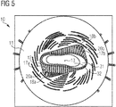
- Fig. 5 shows another exemplary clamping system 10 according to the present invention.
- the clamping system 10 is similar to the clamping system shown in Figs. 1A-C and Fig. 2 .
- the clamping system 10 is for a component 31, 32, especially for an article of footwear or a sports article and comprises: (a) a first member 11; (b) a second member 12, (c) wherein the first member 11 and the second member 12 are rotatable relative to each other about a pivot 13 from a first angle to a second angle; (d) a first bracket 17a, wherein the first bracket 17a is adapted to slidably move along a first path 18a on the first member 11 and a second path 20a, by a first distance, on the second member 12, when the first member 11 and the second member 12 rotate relative to each other; and (e) at least a second bracket 17b, wherein the second bracket 17b is adapted to slidably move along a third path 18b on the first member 11 and a fourth path 20b, by a second distance, on the second member 12, when the first member 11 and the second member 12 rotate relative to each other.
- the clamping system 10 comprises a plurality of brackets 17.
- the clamping system 10 is shown in an angular orientation, in which the plurality of brackets 17 engages the component 31, which, in this case, is a large sole element.
- An overlay shows a small component 32, in this case a small sole element 32, to illustrate the location of the plurality of brackets when the clamping system 10 is rotated further, in order to engage a small component 32 instead of a large component 31.
- the brackets 17 are arranged such as to form a void that has a mixed convex and concave shape for receiving a component 31, 32 that has a mixed convex and concave shape.
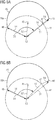
- Fig. 6A illustrates an example of how the displacement of the first bracket upon rotation of the first member relative to the second member from the first angle 14 to the second angle 16 can be determined and engineered.
- Fig. 6A shows an exemplary first path 18a on the first member, although it is to be understood that this could be equally an exemplary third path, for example.
- Fig. 6A is drawn in the reference frame of the first member.
- the exemplary first path 18a comprises a first position 46 and a second position 48, wherein the first position 46 is located at a first-position distance 50 from the pivot 13 and the second position 48 is located at a second-position distance 51 from the pivot 13, wherein first-position distance 50 is smaller than the second-position distance 51, although the first-position distance 50 could alternatively be larger than the second-position distance 51.
- Fig. 6A illustrates the rotation of the clamping system 10 from a first angle 14 to a second angle 16 about a pivot 13.
- Any object that is fixedly attached to the first member will therefore traverse a circular path in the plane of rotation, for example at least part of the exemplary circular path of rotation 41, or circle 41, with respect to the second member.
- any circular path centered on the pivot for example circle 41, is the same in the reference frame of the first member and the second member, since a circular path centered on the pivot is invariant under rotation about the pivot.
- first position 46 may, for example, be defined by a first pin.
- a circular path of rotation 41 centered on the pivot 13 is drawn through the first position 46.
- the first position 46 coincides with the starting position on the circle 46, defined by the first angle.
- a final position 47 on the circular path of rotation 41, in the reference frame of the first member, is then given by the second angle 16.
- a desired first bracket displacement vector 54 is defined, depending on the size and shape of the component to be clamped.
- the first bracket displacement vector 54 comprises a radial component and a non-radial component.
- the vector sum of the final position 47 on the circle and the first bracket displacement vector 54 determines the second position 48 of the bracket on the first path 18a.
- first and second angle are defined with respect to the relative orientation of the first member and the second member, the angle between the first position of the first bracket and the second position of the first bracket, both determined with respect to the pivot, is different to the difference between the first and second angle, because the first bracket displacement vector further comprises a non-radial component.
- the magnitude of the first bracket displacement vector 54 is the first distance, which is determined with respect to the second member.
- the shape of the first path determines the speed of movement of the bracket per unit of change in angular rotation, measured, for example, in mm/°, which may not be constant, but instead depend on the rotation angle.
- Fig. 6B illustrates another example of how the displacement of the first bracket upon rotation of the first member relative to the second member from the first angle 14 to the second angle 16 can be determined and engineered.
- Fig. 6B is drawn in the reference frame of the first member.
- the example of Fig. 6B is substantially similar to the example of Fig. 6A , except that in the example of Fig. 6B the first bracket displacement vector 54 comprises only a radial component and does not comprise a non-radial component. Therefore, in the example of Fig. 6B , the angle between the first position of the first bracket and the second position of the first bracket, both determined with respect to the pivot, is identical to the difference between the first and second angle, because the first bracket displacement vector does not comprise a non-radial component.
- Fig. 7A illustrates an aspect of another exemplary clamping system according to the present invention.
- Fig. 7A shows an exemplary first path 18a on the first member, although it is to be understood that this could equally be an exemplary third path, for example.
- Fig. 7A is drawn in the reference frame of the first member.
- the exemplary first path 18a comprises a first position 46 and a second position 48, wherein the first position 46 is located at a first-position distance 50 from the pivot 13 and the second position 48 is located at a second-position distance 51 from the pivot 13, wherein first-position distance 50 is smaller than the second-position distance 51.
- the first position 46 on the first path 18a coincides with the starting position 46 on the circular path 41, which is determined by the first angle 14.
- the final position on the circular path is indicated by reference numeral 47 and is determined by the second angle 16.
- the first path 18a comprises a first essentially circular segment 49.
- the first path comprises a first position 46 is located at the first end 46, and a second position 48 is located at the second end 48, wherein the first path 18a deviates from an essentially circular shape at the first end 46 by a first deviation vector 43 and at the second end 48 by a second deviation vector 44.
- the center of the first essentially circular segment is located at the pivot 13. Therefore, the difference between the magnitude of the first deviation vector 43 and the magnitude of the second deviation vector 44 yields the first bracket displacement vector 54, which, in the example of Fig. 7A , is oriented along a radial direction.
- Fig. 7B illustrates a similar example to the example shown in Fig. 7A .
- the first bracket displacement vector 54 further comprises a non-radial component.
- Fig. 8A illustrates an aspect of another exemplary clamping system according to the present invention.
- Fig. 8A shows an exemplary first path 18a, although it is to be understood that this could equally be an exemplary third path, for example.
- Fig. 8A is drawn in the reference frame of the first member.
- the exemplary first path 18a comprises a first position 46 and a second position 48, wherein the first position 46 is located at a first-position distance 50 from the pivot 13 and the second position 48 is located at a second-position distance 51 from the pivot 13, wherein first-position distance 50 is smaller than the second-position distance 51.
- the first position 46 on the first path 18a coincides with the starting position 46 on the circular path 41, which is determined by the first angle 14.
- the final position on the circular path is indicated by reference numeral 47 and is determined by the second angle 16.
- the first path 18a comprises a first essentially circular segment 49.
- the first path 18a is essentially circular over its whole length.
- the center 45 of the first path 18a, i.e. of the first segment 49, is displaced by a first displacement vector 52 from the pivot 13.
- the clamping system is rotated from the first angle 14 to the second angle 16.
- the first bracket displacement vector 54 comprises a radial component only.
- the third path may analogously comprise a second essentially circular segment.
- the first segment and the second segment may not be concentric.
- the second segment may have a second center and the second center may be displaced by a second displacement vector from the pivot 13 that is not identical to the first displacement vector 52.
- the second displacement vector may have a larger magnitude than the first displacement vector 52.
- Fig. 8B illustrates a similar example to the example shown in Fig. 8A .
- the first bracket displacement vector 54 displacement vector further comprises a non-radial component.
- first bracket displacement vectors shown in Figs. 6-8 all comprise a radial component, it is to be understood that this is not essential for the invention.
- the first bracket displacement vector may comprise only a non-radial component.
- Fig. 9 illustrates an aspect of another exemplary clamping system according to the present invention.
- Fig. 9 is drawn in the reference frame of the second member, unlike Fig. 6-8 , which are drawn in the reference frame of the first member.
- a corresponding first position 66 of a first bracket is shown.
- the corresponding first position 66 corresponds to the first position of the first bracket in the reference frame of the first member.
- a corresponding second position 68 of the first bracket is shown, which corresponds to the second position in the reference frame of the first member.
- a desired corresponding first bracket displacement vector 64 is defined, depending on the size and shape of the component to be clamped.
- the corresponding first bracket displacement vector 64 determines the magnitude and direction of the displacement of the first bracket with respect to the second member.
- the magnitude of the corresponding first bracket displacement vector 64 is identical to the magnitude of the first bracket displacement vector it corresponds to.
- the direction of the corresponding first bracket displacement vector 64 is parallel to the direction of the first bracket displacement vector it corresponds to, when the first member and the second member are at the second angle relative to each another.
- a first circular path 41a centered on a pivot 13 is drawn at a first radius 60, r 1 which corresponds to the radial distance of the corresponding first position 66 from the pivot 13.
- a second circular path 41b centered on a pivot 13 is drawn at a second radius 61, r 2 , which corresponds to the radial distance of the corresponding second position 68 from the pivot 13.
- the corresponding first bracket displacement vector 64 is not arranged in a radial direction. Instead, it is arranged pointing towards an offset position 63 located at an offset distance 62, d 0 , from the pivot 13.
- exemplary concepts illustrated with reference to Figs. 6-9 serve to illustrate just some possible ways of engineering the first, second, third, and fourth path in order to effect a particular, desired displacement of a first or second brackets, or further brackets, if present.
Landscapes
- Engineering & Computer Science (AREA)
- Mechanical Engineering (AREA)
- General Engineering & Computer Science (AREA)
- Clamps And Clips (AREA)
- Footwear And Its Accessory, Manufacturing Method And Apparatuses (AREA)
Abstract
The invention concerns a clamping system (10) for a component (31, 32), especially for an article of footwear or a sports article, comprising: (a) a first member (11); (b) a second member (12), (c) wherein the first member (11) and the second member (12) are rotatable relative to each other about a pivot (13); (d) a first bracket (17a), wherein the first bracket (17a) is adapted to slidably move along a first path (18a) on the first member (11) and a second path (20a), by a first distance, on the second member (12), when the first member (11) and the second member (12) are rotated relative to each other from a first angle (14) to a second angle (16); and (e) at least a second bracket (17b), wherein the second bracket (17b) is adapted to slidably move along a third path (18b) on the first member (11) and a fourth path (20b), by a second distance, on the second member (12), when the first member (11) and the second member (12) are rotated relative to each other from the first angle (14) to the second angle (16).
Description
- The present invention relates to an improved clamping system, especially for the production of an article of footwear or a sports article.
- Numerous clamping systems are known for temporarily fixing workpieces during assembly. It is frequently required in a production environment to secure workpieces of different sizes for a particular process. In order to allow an accurate and secure arrangement of a workpiece it is presently required to use a number of custom-fitted forms or molds. This is especially true for fragile and / or soft workpieces which cannot be clamped with great force without risking damage to the workpiece.
- For example, an issue in the production of footwear concerns the securing of a midsole during assembly. Present methods involve a number of forms that are fitted specifically for one particular type, size, and side (left/right) of midsole. This leads to a large inventory and lost processing time due to tooling change over.
-
DE 20 2012 004 576 U1 concerns a workpiece carrier for use, for example, on a workpiece conveyor with its own base pallet, on which the workpiece carrier can be mounted in order to bring the workpieces into the engine room. -
DE 80 26 966 U1 concerns a holding- or clamping mechanism. - An object underlying the present invention is therefore to provide an improved clamping system and method that allows even fragile workpieces of different sizes, shapes, and types to be secured during processing in a simple and effective manner.
- This object is accomplished by the teachings of the independent claims and in particular by a clamping system for a component, especially for an article of footwear or a sports article, comprising: (a) a first member; (b) a second member, (c) wherein the first member and the second member are rotatable relative to each other about a pivot; (d) a first bracket, wherein the first bracket is adapted to slidably move along a first path on the first member and a second path, by a first distance, on the second member, when the first member and the second member are rotated relative to each other from a first angle to a second angle; and (e) at least a second bracket, wherein the second bracket is adapted to slidably move along a third path on the first member and a fourth path, by a second distance, on the second member, when the first member and the second member are rotated relative to each other from the first angle to the second angle.
- An article of footwear may be a shoe, a boot, a hiking boot, a running shoe, a football boot, a tennis shoe, a golf shoe, sandal, etc. A sports article may be any type of apparel especially used for sports, or any sports accessory, such as for example, a tennis racket, a baseball bat, a shinguard, a glove, a knee or elbow protector etc.
- A path is understood as a physical path, rather than a potentially mathematically infinite path, a section of which would be the physical path.
- A member is understood as any solid construction, that may consist of just a single piece or may comprise several pieces, which are preferably connected. The member may be essentially rigid, wherein "essentially rigid" means not necessarily rigid in a strictly mathematical sense but allowing for some flexibility inherent to real materials, such as a metal, e.g. aluminium, steel etc., wood, polymers, e.g. acrylonitrile butadiene styrene copolymer (also known as ABS), poly(methyl methacrylate), a polycarbonate etc. The surfaces of each of the members may or may not be flat.
- A bracket is understood to be any moveable item configured for securing the component by contacting and engaging the component. It is to be understood that the clamping system may comprise further brackets, for example a third bracket, a fourth bracket, a fifth bracket etc. The clamping system allows the relative motion of the first bracket and the second bracket to be controlled with a single operation, i.e. the relative rotation of the first member and the second member. Therefore, the system is easy and fast to operate and may be adapted to different sizes of components simply by rotating the first member relative to the second member. It is to be understood that it is not important which member is physically rotated with respect to an external reference frame, such as a workbench. It is only important that a relative rotation of the first member and the second member is performed. A key aspect of the present invention is thus that the first distance and the second distance by which the first and bracket move, respectively, is determined by the first and second angle. In other words, a single parameter, the relative angle of the first and second member, controls the motion of the first bracket, the second bracket, and further brackets, if present.
- The first angle and the second angle are defined with respect to one, i.e. the same, suitable axis. There may be numerous suitable axes, for example the first angle and the second angle may conveniently be measured with respect to an edge of the first member or the second member. It is to be understood that the first angle and the second angle are not necessarily limiting angles, e.g. a minimum or a maximum physically reachable value. In other words, the clamping system may be operable beyond the first and the second angle.
- The rotation axis about which the first member and the second member rotate may be essentially perpendicular to the first member and/or the second member. However, it is also possible that the rotation axis is tilted by a tilting angle with respect to a normal to the surface of the first member and/or a normal to the surface of the second member. This way, the clamping system allows the relative motion of the first bracket and the second bracket to be controlled in three dimensions (relative to the first and / or second member and so also relative to the component). The tilting angle may be at least 5°, or at least 15° to allow a greater control in three dimensions.
- The pivot is located on the rotation axis. However, it is not necessary for a physical joint to be located at the pivot. The rotation mechanism may be located away from the pivot. For example, this may be done by an essentially-circular guiding wheel arranged at an outside of the clamping system, wherein a rotation center of the guiding wheel is located at the pivot. The guiding wheel may be supported from below with a circular bearing. The mechanism driving the motion may be on an outside of the clamping system, for example as a linear actuator acting tangentially to the ring, or with a geared interface, and / or a motor. This may provide more space for a component to be secured by the clamping system.
- Any one of the first path, the second path, the third path, and the fourth path may have any shape, for example approximated by or given by any mathematical function, which may, for example, be defined by an explicit equation or a parametric equation. For example, suitable functions may define a circle, an ellipse, a hyperbola, a trochoid, a cycloid, a parabola, a straight line, a sinusoid, or combinations thereof. The shapes of the paths determine the motion of the first bracket and the second bracket effected by the relative rotation of the first member at the second member. Therefore, the shapes may be selected such that different sizes of components are clamped effectively when engaged by the first bracket and the second bracket. Therefore, the clamping system according to the present invention allows a component to be secured effectively even without application of a large clamping force, thus preventing damage especially to a soft or fragile component.
- Any one of the first path, the second path, the third path, and the fourth path may be located on a surface of the first member or the second member, respectively.
- It is also possible that any one of the first path, the second path, the third path, and the fourth path may be located on an inside of the first member and/or the second member. This arrangement may also allow a three-dimensional control of the first bracket and the second bracket by a single operation, i.e. the relative rotation of the first member and the second member.
- The first member may comprise a first plate and the second member may comprise a second plate. This allows for a simple production of the first member and the second member and enables a great amount of choice for any one of the first path, the second path, the third path, and the fourth path, without the risk of collision between any of the paths, which is preferably avoided.
- The first path may be defined by a first slot arranged in the first member and the third path may be defined by a second slot arranged in the first member. A slot may be any indentation or recess that may or may not extend from a surface to an opposing surface on the first member. This allows a simple, accurate, and fast production of the first member and provides a durable first and third path. For example, a slot may be drilled or milled into the first member. However, other arrangements are possible. For example, the first path may be defined by a first guide rail or a first pair of guide rails and the third path may be defined by a second guide rail or a second pair of guide rails.
- The first bracket may be attached to a first pin and / or the second bracket may be attached to a second pin, wherein the first and / or the second pin is/are arranged in the first slot or the second slot, respectively. A pin may have approximate rotational symmetry such as to facilitate low-friction sliding along the first and second slot. In particular, the first bracket may be essentially rigidly attached to a first pin and / or the second bracket may be essentially rigidly attached to a second pin. "Essentially rigidly attached" means not allowing for any relative motion except due to some flexibility of the material and manufacturing tolerances. This setup using a pin may be produced simply and accurately and allows for an accurate control of the first bracket and the second bracket with low wear and tear.
- The first pin and / or the second pin may further comprise means for attaching the first pin and / or the second pin to the first member such that the first pin and / or the second pin may slide along the first slot or the second slot, respectively, but cannot move out of the first slot or the second slot, respectively. For example, suitable means for attaching for this purpose may be a nut tightened around a threaded pin. This way, the clamping system is more robust and may be used with a reduced need for maintenance in an industrial production environment.
- The second path may be defined by a first channel arranged in the second member and the fourth path may be defined by a second channel arranged in the second member. A channel may be any indentation or recess that may or may not extend from a surface to an opposing surface of the second member. This allows a simple, accurate, and fast production of the second member and provides a durable second and fourth path. For example, a channel may be drilled or milled into the second member. However, other arrangements are possible. For example, the second path may be defined by a third guide rail or a third pair of guide rails and the fourth path may be defined by a fourth guide rail or a fourth pair of guide rails.
- The first bracket may be attached to a first slider and / or the second bracket may be attached to a second slider and the first and / or the second slider may be arranged in the first channel or the second channel, respectively. Each bracket may be attached to one slider to allow a spatially-efficient arrangement.
- The first bracket may further be attached to a third slider and / or the second bracket may further be attached to a fourth slider. The third and / or the fourth slider may be arranged in a third channel or a fourth channel, respectively. In other words, the first bracket and / or the second bracket may be attached to two sliders. This allows a more stable locking-mechanism of the first and /or second bracket and may prevent twisting and uneven bending forces.
- The third channel may be essentially parallel to the first channel and the fourth channel may be essentially parallel to the second channel. In general, the first bracket and / or the second bracket may be attached to further sliders.
- The first bracket may be essentially rigidly attached to a first slider (or possible further sliders such as the third slider) and / or the second bracket may be essentially rigidly attached to a second slider (or possible further sliders such as the fourth slider). This setup using a slider may be produced simply and accurately and allows for an accurate control of the first bracket and the second bracket with low wear and tear. A slider may be a protrusion similar to a pin. A slider may lack rotational symmetry such as to prevent rotation of the first bracket and/or the second bracket with respect to the second member. However, it is also possible that a non-rotationally-symmetric slider may be attached to the first bracket or the second bracket, respectively, using a rotatable attachment mechanism. The inventors have found that this may improve the stability of the clamping system.
- The first slider and / or the second slider (or any further sliders) may further comprise means for attaching the first slider and / or the second slider to the second member such that the first slider and / or the second slider may slide along the first channel or the second channel, respectively, but cannot move out of the first channel or the second channel, respectively. For example, suitable means for attaching for this purpose may be a nut tightened around a threaded slider, or groves formed on the sides of the slider. This way, the clamping system is more robust and may be used with a reduced need for maintenance in an industrial production environment.
- Any of the pins, sliders, slots, or channels may comprise a durable, low friction material, e.g. polytetrafluoroethylene (PTFE), which may be applied as a surface coating or in the bulk of any of these parts.
- The first bracket and / or the second bracket may be rotatable with respect to the first member and / or the second member. In particular, the first bracket and / or the second bracket may be rotatable with respect to the second member. This additional degree of freedom may allow a better grip of the first bracket and/or the second bracket of the component. However, it is also possible that the first bracket and / or the second bracket are not rotatable with respect to the second member. This arrangement is simpler and may be more stable.
- Rotation of the first member relative to the second member from the first angle to the second angle may cause the first bracket and / or the second bracket to move towards the component. Therefore, the clamping system engages the component when rotating the first member relative to the second member from the first angle to the second angle. It should be noted that the clamping system, in particular the first bracket and the second bracket, may already engage the component before the full range of motion of the clamping system has been exploited, i.e. before the second angle has been reached, when starting from the first angle.
- The second distance may be greater than the first distance. In other words, the first bracket and the second bracket may move in a non-symmetric, non-circular manner, when rotating the first member relative to the second member. An important insight of the inventors was that many components have an irregular shape. Therefore, the differences between different sizes of a component may be greater in some areas than in other areas. This arrangement therefore improves the accuracy of the grip for different sizes of components.
- It is important to understand, that a different movement of the first bracket and the second bracket, e.g. a second distance that is greater than the first distance, may be achieved for numerous shapes of the first and third path.
- Rotation of the first member relative to the second member from the first angle to the second angle may cause the first bracket to move towards the second bracket. For example, the first bracket and the second bracket may be located on opposite sides of the component. Therefore, this arrangement allows a particularly good grip on the component.
- The second path and the fourth path may be essentially linear. This arrangement may allow for a simple construction as well as a low wear and tear, e.g. on the first and second slider (or any further sliders).
- The first path may comprise a first position and a second position, wherein the first position may be located at a first-position distance from the pivot and the second position may be located at a second-position distance from the pivot, wherein first-position distance may be different from the second-position distance; and / or the third path may comprise a third position and a fourth position, wherein the third position may be located at a third-position distance from the pivot and the fourth position may be located at a fourth-position distance from the pivot, wherein the third-position distance may be different from the fourth-position distance.
- By rotating the first member relative to the second member such that the first bracket slidably moves along the first path from the first position to the second position, the first bracket moves relative to the second member. The first position may correspond to the first angle and the second position may correspond to the second angle. If the first-position distance is different from the second-position distance, a first bracket displacement vector, defining the direction and magnitude of displacement of the first bracket, comprises a radial component with respect to the pivot. The inventors have found this is especially effective in achieving a good clamping effect, since it means that the component is pushed towards or away from the pivot by the first bracket. Similarly, by rotating the first member relative to the second member such that the second bracket slidably moves along the third path from the third position to the fourth position, the second bracket moves relative to the second member. The third position may correspond to the first angle and the fourth position may correspond to the second angle. If the third-position distance is different from the fourth-position distance, a second bracket displacement vector, defining the direction and magnitude of displacement of the second bracket, comprises a radial component with respect to the pivot. The inventors have found this is especially effective in achieving a good clamping effect, since it means that the component is pushed towards or away from the pivot by the second bracket.
- Clamping is particularly effective if the first-position distance is different from the second-position distance and the third-position distance is different from the fourth-position distance. In this case, the first bracket pushes the component radially towards or away from the pivot and the second bracket pushes the component radially towards or away from the pivot. Thus, the first bracket and the second bracket may, in some configurations, clamp the component between them, without the need for further structural elements to guide or hold the component.
- The displacement of the first bracket upon rotation of the first member relative to the second member from the first angle to the second angle can be determined and engineered as follows. The rotation of the first member relative to the second member causes a circular motion of the first member relative to the second member in the plane of rotation. A first position of the first bracket is defined. Physically the first position may, for example, be defined by a first position of a first pin. A circle centered on the pivot is drawn through the first position, thus also defining a starting position on the circle, which may be selected to coincide with the first position. A final position on the circle, in the reference frame of the first member is determined by the starting position, the first angle, and the second angle, wherein the first and second angle are defined by the relative orientation of the first member and the second member. A desired first bracket displacement vector is defined. The first bracket displacement vector may be arranged radially pointing away or towards the pivot. However, it is also possible that the first bracket displacement vector further comprises a non-radial component. The vector sum of the final position on the circle and the first bracket displacement vector determines the second position on the first path. Since the first and second angle are defined with respect to the relative orientation of the first member and the second member, the angle between the first position of the first bracket and the second position of the first bracket, both determined with respect to the pivot, is not identical to the difference between the first and second angle, if the first bracket displacement vector further comprises a non-radial component.
- The first bracket is constrained to slidably move at least partly along the second path. Therefore, in the simple case in which the second path is linear, the first bracket displacement vector is parallel to a second path vector, which is defined by the direction of the second path, in the reference frame of the second member. It is to be understood, that a similar method may be applied to determine the displacement of the second bracket or any additional brackets, if present, upon rotation of the first member relative to the second member from the first angle to the second angle.
- The first path may comprise a first essentially circular segment and / or the third path may comprise a second essentially circular segment. "Essentially circular" means, in this context, that the first segment and / or the second segment need not be mathematically perfect segments but may allow for manufacturing tolerances. This arrangement may allow for a simple construction and a smooth movement of the first and second bracket, therefore helping to prevent damage to the component due to a sudden movement of the first and second bracket. Moreover, it helps to ensure that the first and second bracket move at the same speed when the first member and the second member are rotated relative to each other about the pivot thus allowing an effective clamping without an undesirable movement of the component, that may be caused by clamps that move at different speeds.
- The first path may comprise a first end and a second end, wherein the first path may deviate from an essentially circular shape at the first end by a first deviation vector and / or at the second end by a second deviation vector; and / or
wherein the third path may comprise a third end and a fourth end, wherein the third path may deviate from an essentially circular shape at the third end by a third deviation vector and / or at the fourth end by a fourth deviation vector. - The center of the first essentially circular segment may be located at the pivot. Therefore, the sum of the first and the second deviation vector may yield the first distance. Additionally, or alternatively, the center of the second essentially circular segment may be located at the pivot. Therefore, the sum of the third and the fourth deviation vector may yield the second distance.
- This arrangement allows for a simple arrangement of the clamping system.
- The first segment and the second segment may not be concentric. In the case that the first and second segment are essentially circular, the arrangement wherein the first segment and the second segment are not concentric allows a simple way of effecting a different motion of the first bracket compared to the second bracket, in order to improve the accuracy of the grip for different sizes of components as described herein.
- The first segment may have a first center and the second segment path may have a second center and the first center may be displaced by a first displacement vector from the pivot and the second center may be displaced by a second displacement vector from the pivot that is not identical to the first displacement vector. This arrangement allows improved control of the motion of the first bracket and the second bracket in order to improve the accuracy of the grip for different sizes of components as described herein.
- The second displacement vector may have a larger magnitude than the first displacement vector. The inventors have found that, the greater the displacement vector, the greater the motion of the respective bracket may be, that is effected by a rotation of the first member relative to the second member by a given rotation angle. Therefore, this arrangement effects a larger movement of the second bracket compared to the first bracket, thus improving the accuracy of the grip for different sizes of components as described herein. The first, second, third, and fourth path may be selected such as to engineer a different timing and / or speed of the first and second bracket.
- The clamping system may comprise at least three brackets and the three brackets may be arranged such as to form a convex void for receiving a convex component in at least one angular orientation of the first and second member. It is also possible that the void comprises a concave shape or a mixed concave and convex shape, i.e. a first part of the void may be convex while a second part of the void may be concave. Many components may have a convex shape for at least a portion of the component, for example much of a forefoot region of an article of footwear has a convex shape. Therefore, the grip is improved for components that comprise a convex shape. However, the three brackets may alternatively be arranged to create a concave void for receiving a concave component in at least one angular orientation of the first and second member.
- The component may be a sole element of an article of footwear. Sole elements may be fragile and / or soft and thus the clamping system according to the present invention is particularly beneficial for securing a sole element for an article of footwear, e.g. during production or repair.
- The second bracket may be configured to contact a forefoot portion of the sole element and the first bracket may be configured to contact a rearfoot portion of the sole element. The inventors have found that this arrangement may be advantageous to achieve a minimum level of grip. Moreover, the differences between different sizes of an article of footwear may be greater in a forefoot portion than in a rear foot portion. Therefore, the combination of this feature and the feature wherein the second distance may be greater than the first distance, is particularly advantageous as rotation of the first member and the second member by a given angle therefore leads to a greater attraction or advancement of the second bracket in a forefoot portion than of the first bracket in their rear foot portion.
- At least one of: the first bracket, the second bracket, the first element, or the second element, may comprise a metal, e.g. aluminium, steel etc. A metal may generally offer a good level of durability. Alternatively or additionally the first bracket, the second bracket, the first element, and / or the second element, may comprise wood, polymers, e.g. acrylonitrile butadiene styrene copolymer (also known as ABS), poly(methyl methacrylate), a polycarbonate etc, which are also durable but more lightweight.
- The invention further concerns a method of securing a component, especially for an article of footwear or a sports article, comprising using a clamping system according to the present invention. The advantages of a clamping system according to the present invention therefore lead to an improved method of securing a component.
- The using may comprise: (a) rotating the first plate to the first angle relative to the second plate; (b) arranging the component proximate to the first and the second bracket; and (c) rotating the first plate to the second angle relative to the second plate such that the first and / or second brackets touches the component.
- In other words, the first angle and the second angle may represent the opening and closing position of the clamping system for a particular application based, for example, on the properties of the component, especially its size and shape, and the procedure to be performed. It should be understood that any or all steps of this method may be performed automatically, for example by a computer-controlled system.
- The component may be a sole element. It was already described herein, why the clamping system according to the present invention may be particularly advantageous for securing a sole element.
- The sole element may comprise a midsole. A midsole is generally quite soft, especially compared with an outsole. Therefore, the present method is particularly advantageous and may help to prevent damage to a soft and fragile midsole. The sole element may further comprise an outsole.
- The method may further comprise attaching a portion of an upper to the midsole, when the sole element is secured in the clamping system. This is an important step in the production of footwear. It is important that the sole element is secured well during this production step, since once the portion of the sole element is secured to the upper, it may not be possible to adjust their arrangement without damaging the article of footwear.
- The attaching may comprise welding. Welding, for example infrared welding, maybe advantageous since it does not involve the use of solvents. Furthermore, a particularly secure connection may be achieved if two similar materials, for example two materials comprising a same thermoplastic polymer, are welded together.
- In the following, exemplary embodiments of the invention are described with reference to the figures. The figures show:
- Figs. 1A-C:
- shows an exemplary clamping system according to the present invention in operation;
- Fig. 2:
- shows a close-up lateral view of the exemplary clamping system shown in
Figs. 1A-C ; - Fig. 3:
- shows an exemplary close-up view of a second member of the exemplary clamping system shown in
Figs. 1A-C ; - Fig. 4:
- shows an exemplary close-up view of part of the brackets and channels of the exemplary clamping system shown in
Figs. 1A-C ; - Fig. 5:
- shows another exemplary clamping system according to the present invention;
- Figs. 6A-
- illustrate an aspect of an exemplary clamping system according to the
- B:
- present invention in the reference frame of the first member;
- Figs. 7A-
- illustrate an aspect of another exemplary clamping system according to
- B:
- the present invention in the reference frame of the first member;
- Figs. 8A-
- illustrate an aspect of another exemplary clamping system according to
- B:
- the present invention in the reference frame of the first member; and
- Fig. 9:
- illustrates an aspect of another exemplary clamping system according to the present invention in the reference frame of the second member.
- In the following, only some possible embodiments of the invention are described in detail. It is to be understood that these exemplary embodiments can be modified in a number of ways and combined with each other whenever compatible and that certain features may be omitted in so far as they appear dispensable. The figures merely illustrate the principle of operation, numerous modifications are possible. The clamping system may be smaller or larger and in particular may surround, substantially on all sides, a space configured to receive a component.
-
Figs. 1A-C show anexemplary clamping system 10 according to the present invention in different stages of operation.Fig. 1A shows theclamping system 10 when thefirst member 11 and thesecond member 12 are at afirst angle α 14,Fig. 1B shows theclamping system 10 when thefirst member 11 and thesecond member 12 are at anintermediate angle β 15, andFig. 1C shows theclamping system 10 when thefirst member 11 and thesecond member 12 are at asecond angle γ 16. The space configured to receive the component is at the bottom end of the clamping system. - The
clamping system 10 is for a component, especially for an article of footwear or a sports article and comprises: (a) afirst member 11; (b) asecond member 12, (c) wherein thefirst member 11 and thesecond member 12 are rotatable relative to each other about apivot 13 from afirst angle 14 to asecond angle 16; (d) afirst bracket 17a, wherein thefirst bracket 17a is adapted to slidably move along afirst path 18a on thefirst member 11 and a second path, by a first distance, on thesecond member 12, when thefirst member 11 and thesecond member 12 rotate relative to each other; and (e) at least asecond bracket 17b, wherein thesecond bracket 17b is adapted to slidably move along athird path 18b on thefirst member 11 and afourth path 20b, by a second distance, on thesecond member 12, when thefirst member 11 and thesecond member 12 rotate relative to each other. - In the present example, the
clamping system 10 comprises further brackets, in this case a total of 12 brackets. Theclamping system 10 allows the relative motion of each of the brackets to be controlled with a single operation, i.e. the relative rotation of thefirst member 11 and thesecond member 12. The brackets are arranged such as to form a convex void for receiving a convex component in at least one angular orientation of the first andsecond member 12. - This motion can be seen from a comparison of
Figs. 1A-C , whereinFig. 1A shows an "open" configuration of theclamping system 10,Fig. 1B an intermediate configuration, andFig. 1C shows a "closed", i.e. engaging, configuration of theclamping system 10. - Therefore, the system is easy and fast to operate and may be adapted to different sizes of components simply by rotating the
first member 11 relative to thesecond member 12. Thefirst angle 14 and thesecond angle 16 are defined with respect to one, i.e. the same, suitable axis. In this example, thefirst angle 14 and thesecond angle 16 are conveniently defined with respect to an edge of thefirst member 11 and thesecond member 12. - In this example, the rotation axis about which the
first member 11 and thesecond member 12 rotate is essentially perpendicular to thefirst member 11 and thesecond member 12. However, it is also possible that the rotation axis is tilted by a tilting angle with respect to a normal to the surface of thefirst member 11 and/or a normal to the surface of thesecond member 12. - The
first path 18a, the second path, thethird path 18b, and thefourth path 20b are located on a surface of thefirst member 11 or thesecond member 12, respectively. However, it is also possible that any one of thefirst path 18a, the second path, thethird path 18b, and thefourth path 20b is located on an inside of thefirst member 11 and/or thesecond member 12. Thefirst member 11 comprises a first plate and thesecond member 12 comprises a second plate. - The
first path 18a is defined by a first slot arranged in thefirst member 11 and thethird path 18b is defined by a second slot arranged in thefirst member 11. However, other arrangements are possible. For example, thefirst path 18a may be defined by a first guide rail or a first pair of guide rails and thethird path 18b may be defined by a second guide rail or a second pair of guide rails. - The
first bracket 17a is attached to afirst pin 19a and thesecond bracket 17b is attached to asecond pin 19b, wherein the first 19a and thesecond pin 19b are arranged in the first slot and the second slot, respectively. The exemplary pins have approximate rotational symmetry such as to facilitate low-friction sliding in the first and second slot, respectively. In particular, thefirst bracket 17a is essentially rigidly attached to afirst pin 19a and thesecond bracket 17b is essentially rigidly attached to asecond pin 19b. - In this example, neither the
first pin 19a nor thesecond pin 19b comprises means for attaching thefirst pin 19a and thesecond pin 19b to thefirst member 11 such that thefirst pin 19a and thesecond pin 19b may slide along the first slot or the second slot, respectively, but cannot move out of the first slot or the second slot, respectively. However, in other embodiments, thefirst pin 19a and / or thesecond pin 19b may comprise such means. - The second path (not shown) is defined by a first channel (not shown) arranged in the
second member 12 and thefourth path 20b (visible inFig. 1A only) is defined by a second channel arranged in thesecond member 12. The exemplary channels are an indentation or recess that may or may not extend from a surface to an opposing surface on thesecond member 12. However, other arrangements are possible. For example, the second path may be defined by a third guide rail or a third pair of guide rails and thefourth path 20b may be defined by a fourth guide rail or a fourth pair of guide rails. - The exemplary first and
second brackets 17b are rotatable with respect to thefirst member 11 and thesecond member 12. This additional degree of freedom allows a better grip of the first bracket and thesecond bracket 17b of the component. - Rotation of the
first member 11 relative to thesecond member 12 from thefirst angle 14 to thesecond angle 16 causes thefirst bracket 17a and thesecond bracket 17b to move towards the component (component not shown). Therefore, theclamping system 10 engages the component when rotating thefirst member 11 relative to thesecond member 12 from thefirst angle 14 to thesecond angle 16. - In this example, the second distance may be greater than the first distance. In other words, the
first bracket 17a and thesecond bracket 17b may move in a non-symmetric, non-circular manner, when rotating thefirst member 11 relative to thesecond member 12. This can be seen very well by comparingFigs. 1A-C , which shows that thesecond bracket 17b moves a lot more than thefirst bracket 17a. An important insight of the inventors was that many components have an irregular shape. Therefore, the differences between different sizes of a component may be greater in some areas than in other areas. Therefore, the accuracy of the grip for different sizes of components may be improved. - Rotation of the
first member 11 relative to thesecond member 12 from thefirst angle 14 to thesecond angle 16 causes thefirst bracket 17a to move towards thesecond bracket 17b. In some embodiments, thefirst bracket 17a and thesecond bracket 17b may be located on opposite sides of the component. - In this example, the
first path 18a comprises a first essentially circular segment and thethird path 18b comprises a second essentially circular segment. In particular thefirst path 18a and thethird path 18b are sections of a circle, rather than a complete circle. Thefirst path 18a and thethird path 18b are not concentric. Thefirst path 18a has a first center and thethird path 18b has a third center and the first center is displaced by a first displacement vector from thepivot 13 and the third center is displaced by a third displacement vector from thepivot 13 that is not identical to the first displacement vector. The third displacement vector has a larger magnitude than the first displacement vector. - However, it is important to understand, that a different movement of the
first bracket 17a and thesecond bracket 17b, e.g. a second distance that is greater than the first distance, may equally be achieved for other shapes of the first andthird path 18b. - In this example, the component (not shown) is a sole element of an article of footwear and the
second bracket 17b is configured to contact a forefoot portion of the sole element and thefirst bracket 17a is configured to contact a rearfoot portion of the sole element. - In this example, the
first bracket 17a, thesecond bracket 17b, the first element, and the second element comprise aluminium. - In the present case, the
pivot 14 is determined by a rotary mechanism located at thepivot 14 itself, i.e. located near the final position of thefirst bracket 17a and some of the other brackets. However, it is possible to move the mechanical rotary mechanism to another position, e.g. around an outside of the clamping system, while maintaining the pivot in the same position. For example, this may be done by an essentially-circular guiding wheel arranged at an outside of the clamping system, wherein a rotation center of the guiding wheel is located at the pivot. This may provide more space for a component to be secured by the clamping system. -
Fig. 2 shows a close-up lateral view of theexemplary clamping system 10 shown inFigs. 1A-C . - In particular,
Fig. 2 shows thesecond channel 20b arranged in thesecond member 12. The first bracket is attached to a first slider (not shown) and thesecond bracket 17b is attached to asecond slider 21b and the first and thesecond slider 21b are arranged in the first channel /second channel 20b, respectively. In this example, the first bracket is further attached to a third slider arranged in a third channel and thesecond bracket 17b is further attached to a fourth slider arranged in a fourth channel (not shown). The third channel is essentially parallel to the first channel and the fourth channel is essentially parallel to the second channel. The first, second, third, and fourth sliders are essentially similar. In particular, thefirst bracket 17a is essentially rigidly attached to the first and third slider and thesecond bracket 17b is essentially rigidly attached to the second 21b and fourth slider. The exemplary sliders lack rotational symmetry such as to prevent rotation of thefirst bracket 17a and thesecond bracket 17b with respect to thesecond member 12. The non-rotationally-symmetric sliders are attached to thefirst bracket 17a and thesecond bracket 17b, respectively, using aspacer 24. -
Fig. 3 shows an exemplary close-up view of a bottom side of thesecond member 12 of theexemplary clamping system 10 shown inFigs. 1A-C . -
Fig. 3 shows a plurality ofchannels 22. In this example, there is more than onechannel 22 per bracket. Each path, including the second path and thefourth path 20b is essentially linear. - Each
slider 21, including the first slider and the second slider further comprises means for attaching theslider 21 to thesecond member 12 such that the slider may slide along therespective channel 22, but cannot move out of therespective channel 22. In this example, eachslider 21 contains two parts, an upper part and a lower part which form a groove in between. The upper and lower part of eachslider 21 are fixed to each other using two screws. This allows an easy way of securing the sliders. - In this example the sliders comprise polytetrafluoroethylene (PTFE) in the bulk of any of these parts.
-
Fig. 4 shows an exemplary close-up view of part of thebrackets 17 andchannels 22 of theexemplary clamping system 10 shown inFigs. 1A-C . In particular, to further improve the adjustability of the system, the brackets each contain severalsmall recesses 23. This way, the position of a pin connected to abracket 17 may be adjusted in order to further improve the grip of a component. The ends of thebrackets 17 configured to engage the component are at the bottom end ofFig. 4 . -
Fig. 5 shows anotherexemplary clamping system 10 according to the present invention. Theclamping system 10 is similar to the clamping system shown inFigs. 1A-C andFig. 2 . - The
clamping system 10 is for acomponent first member 11; (b) asecond member 12, (c) wherein thefirst member 11 and thesecond member 12 are rotatable relative to each other about apivot 13 from a first angle to a second angle; (d) afirst bracket 17a, wherein thefirst bracket 17a is adapted to slidably move along afirst path 18a on thefirst member 11 and asecond path 20a, by a first distance, on thesecond member 12, when thefirst member 11 and thesecond member 12 rotate relative to each other; and (e) at least asecond bracket 17b, wherein thesecond bracket 17b is adapted to slidably move along athird path 18b on thefirst member 11 and afourth path 20b, by a second distance, on thesecond member 12, when thefirst member 11 and thesecond member 12 rotate relative to each other. - In this example, the
clamping system 10 comprises a plurality ofbrackets 17. Theclamping system 10 is shown in an angular orientation, in which the plurality ofbrackets 17 engages thecomponent 31, which, in this case, is a large sole element. An overlay shows asmall component 32, in this case a smallsole element 32, to illustrate the location of the plurality of brackets when theclamping system 10 is rotated further, in order to engage asmall component 32 instead of alarge component 31. - The
brackets 17 are arranged such as to form a void that has a mixed convex and concave shape for receiving acomponent -
Fig. 6A illustrates an example of how the displacement of the first bracket upon rotation of the first member relative to the second member from thefirst angle 14 to thesecond angle 16 can be determined and engineered.Fig. 6A shows an exemplaryfirst path 18a on the first member, although it is to be understood that this could be equally an exemplary third path, for example.Fig. 6A is drawn in the reference frame of the first member. - The exemplary
first path 18a comprises afirst position 46 and asecond position 48, wherein thefirst position 46 is located at a first-position distance 50 from thepivot 13 and thesecond position 48 is located at a second-position distance 51 from thepivot 13, wherein first-position distance 50 is smaller than the second-position distance 51, although the first-position distance 50 could alternatively be larger than the second-position distance 51. -
Fig. 6A illustrates the rotation of theclamping system 10 from afirst angle 14 to asecond angle 16 about apivot 13. Any object that is fixedly attached to the first member will therefore traverse a circular path in the plane of rotation, for example at least part of the exemplary circular path ofrotation 41, orcircle 41, with respect to the second member. It is to be understood that any circular path centered on the pivot, forexample circle 41, is the same in the reference frame of the first member and the second member, since a circular path centered on the pivot is invariant under rotation about the pivot. - Numerous shapes of the
first path 18a are possible. Physically thefirst position 46 may, for example, be defined by a first pin. A circular path ofrotation 41 centered on thepivot 13 is drawn through thefirst position 46. Thefirst position 46 coincides with the starting position on thecircle 46, defined by the first angle. Afinal position 47 on the circular path ofrotation 41, in the reference frame of the first member, is then given by thesecond angle 16. A desired firstbracket displacement vector 54 is defined, depending on the size and shape of the component to be clamped. In this example, the firstbracket displacement vector 54 comprises a radial component and a non-radial component. The vector sum of thefinal position 47 on the circle and the firstbracket displacement vector 54 determines thesecond position 48 of the bracket on thefirst path 18a. Since the first and second angle are defined with respect to the relative orientation of the first member and the second member, the angle between the first position of the first bracket and the second position of the first bracket, both determined with respect to the pivot, is different to the difference between the first and second angle, because the first bracket displacement vector further comprises a non-radial component. The magnitude of the firstbracket displacement vector 54 is the first distance, which is determined with respect to the second member. - The shape of the first path determines the speed of movement of the bracket per unit of change in angular rotation, measured, for example, in mm/°, which may not be constant, but instead depend on the rotation angle.
-
Fig. 6B illustrates another example of how the displacement of the first bracket upon rotation of the first member relative to the second member from thefirst angle 14 to thesecond angle 16 can be determined and engineered.Fig. 6B is drawn in the reference frame of the first member. The example ofFig. 6B is substantially similar to the example ofFig. 6A , except that in the example ofFig. 6B the firstbracket displacement vector 54 comprises only a radial component and does not comprise a non-radial component. Therefore, in the example ofFig. 6B , the angle between the first position of the first bracket and the second position of the first bracket, both determined with respect to the pivot, is identical to the difference between the first and second angle, because the first bracket displacement vector does not comprise a non-radial component. -
Fig. 7A illustrates an aspect of another exemplary clamping system according to the present invention.Fig. 7A shows an exemplaryfirst path 18a on the first member, although it is to be understood that this could equally be an exemplary third path, for example.Fig. 7A is drawn in the reference frame of the first member. - The exemplary
first path 18a comprises afirst position 46 and asecond position 48, wherein thefirst position 46 is located at a first-position distance 50 from thepivot 13 and thesecond position 48 is located at a second-position distance 51 from thepivot 13, wherein first-position distance 50 is smaller than the second-position distance 51. Thefirst position 46 on thefirst path 18a coincides with the startingposition 46 on thecircular path 41, which is determined by thefirst angle 14. The final position on the circular path is indicated byreference numeral 47 and is determined by thesecond angle 16. - The example shown in
Fig. 7A is similar to the example shown inFig. 6B . However, in the example ofFig. 7A , thefirst path 18a comprises a first essentiallycircular segment 49. The first path comprises afirst position 46 is located at thefirst end 46, and asecond position 48 is located at thesecond end 48, wherein thefirst path 18a deviates from an essentially circular shape at thefirst end 46 by afirst deviation vector 43 and at thesecond end 48 by asecond deviation vector 44. The center of the first essentially circular segment is located at thepivot 13. Therefore, the difference between the magnitude of thefirst deviation vector 43 and the magnitude of thesecond deviation vector 44 yields the firstbracket displacement vector 54, which, in the example ofFig. 7A , is oriented along a radial direction. -
Fig. 7B illustrates a similar example to the example shown inFig. 7A . However, in the example ofFig. 7B , the firstbracket displacement vector 54 further comprises a non-radial component. -
Fig. 8A illustrates an aspect of another exemplary clamping system according to the present invention.Fig. 8A shows an exemplaryfirst path 18a, although it is to be understood that this could equally be an exemplary third path, for example.Fig. 8A is drawn in the reference frame of the first member. - The exemplary
first path 18a comprises afirst position 46 and asecond position 48, wherein thefirst position 46 is located at a first-position distance 50 from thepivot 13 and thesecond position 48 is located at a second-position distance 51 from thepivot 13, wherein first-position distance 50 is smaller than the second-position distance 51. Thefirst position 46 on thefirst path 18a coincides with the startingposition 46 on thecircular path 41, which is determined by thefirst angle 14. The final position on the circular path is indicated byreference numeral 47 and is determined by thesecond angle 16. - In this example, the
first path 18a comprises a first essentiallycircular segment 49. In this case, thefirst path 18a is essentially circular over its whole length. Thecenter 45 of thefirst path 18a, i.e. of thefirst segment 49, is displaced by afirst displacement vector 52 from thepivot 13. The clamping system is rotated from thefirst angle 14 to thesecond angle 16. In this example, the firstbracket displacement vector 54 comprises a radial component only. - In regard of a third path (not shown), the third path may analogously comprise a second essentially circular segment. The first segment and the second segment may not be concentric. The second segment may have a second center and the second center may be displaced by a second displacement vector from the
pivot 13 that is not identical to thefirst displacement vector 52. The second displacement vector may have a larger magnitude than thefirst displacement vector 52. -
Fig. 8B illustrates a similar example to the example shown inFig. 8A . However, in the example ofFig. 8B , the firstbracket displacement vector 54 displacement vector further comprises a non-radial component. - While the exemplary first bracket displacement vectors shown in
Figs. 6-8 all comprise a radial component, it is to be understood that this is not essential for the invention. The first bracket displacement vector may comprise only a non-radial component. -
Fig. 9 illustrates an aspect of another exemplary clamping system according to the present invention.Fig. 9 is drawn in the reference frame of the second member, unlikeFig. 6-8 , which are drawn in the reference frame of the first member. - A corresponding
first position 66 of a first bracket is shown. The correspondingfirst position 66 corresponds to the first position of the first bracket in the reference frame of the first member. A correspondingsecond position 68 of the first bracket is shown, which corresponds to the second position in the reference frame of the first member. A desired corresponding firstbracket displacement vector 64 is defined, depending on the size and shape of the component to be clamped. The corresponding firstbracket displacement vector 64 determines the magnitude and direction of the displacement of the first bracket with respect to the second member. The magnitude of the corresponding firstbracket displacement vector 64 is identical to the magnitude of the first bracket displacement vector it corresponds to. The direction of the corresponding firstbracket displacement vector 64 is parallel to the direction of the first bracket displacement vector it corresponds to, when the first member and the second member are at the second angle relative to each another. In practice one may, for example, first define a corresponding firstbracket displacement vector 64 in the reference frame of the second member and then define the first bracket displacement vector in the reference frame of the first member, which corresponds to the corresponding firstbracket displacement vector 64. - A first
circular path 41a centered on apivot 13 is drawn at afirst radius 60, r 1 which corresponds to the radial distance of the correspondingfirst position 66 from thepivot 13. A secondcircular path 41b centered on apivot 13 is drawn at asecond radius 61, r 2, which corresponds to the radial distance of the correspondingsecond position 68 from thepivot 13. - As can be seen from
Fig. 9 , the corresponding firstbracket displacement vector 64 is not arranged in a radial direction. Instead, it is arranged pointing towards an offsetposition 63 located at an offsetdistance 62, d 0, from thepivot 13. - The first distance d 1 is the magnitude of the corresponding first
bracket displacement vector 64 and is given by
- The exemplary concepts illustrated with reference to
Figs. 6-9 serve to illustrate just some possible ways of engineering the first, second, third, and fourth path in order to effect a particular, desired displacement of a first or second brackets, or further brackets, if present. - In the following, further embodiments are described in order to illustrate aspects according to the present invention:
- 1. A clamping system (10) for a component (31, 32), especially for an article of footwear or a sports article, comprising:
- (a) a first member (11);
- (b) a second member (12),
- (c) wherein the first member (11) and the second member (12) are rotatable relative to each other about a pivot (13);
- (d) a first bracket (17a), wherein the first bracket (17a) is adapted to slidably move at least partly along a first path (18a) on the first member (11) and at least partly along a second path (20a), by a first distance, on the second member (12), when the first member (11) and the second member (12) are rotated relative to each other from a first angle (14) to a second angle (16); and
- (e) at least a second bracket (17b), wherein the second bracket (17b) is adapted to slidably move at least partly along a third path (18b) on the first member (11) and at least partly along a fourth path (20b), by a second distance, on the second member (12), when the first member (11) and the second member (12) are rotated relative to each other from the first angle (14) to the second angle (16).
- 2. The clamping system (10) according to the preceding embodiment, wherein the first member (11) comprises a first plate and the second member (12) comprises a second plate.
- 3. The clamping system (10) according to the preceding embodiment, wherein the first path (18a) is defined by a first slot arranged in the first member (11) and wherein the third path (18b) is defined by a second slot arranged in the first member (11).
- 4. The clamping system (10) according to the preceding embodiment, wherein the first bracket (17a) is attached to a first pin (19a) and / or the second bracket (17b) is attached to a second pin (19b), wherein the first (19a) and / or the second pin (19b) is/are arranged in the first slot or the second slot, respectively.
- 5. The clamping system (10) according to the preceding embodiment, wherein the first pin (19a) and / or the second pin (19b) further comprises means for attaching the first pin (19a) and / or the second pin (19b) to the first member (11) such that the first pin (19a) and / or the second pin (19b) may slide along the first slot or the second slot, respectively, but cannot move out of the first slot or the second slot, respectively.
- 6. The clamping system (10) according to one of the preceding embodiments, wherein the second path (20a) is defined by a first channel arranged in the second member (12) and wherein the fourth path (20b) is defined by a second channel arranged in the second member (12).
- 7. The clamping system (10) according to the preceding embodiment, wherein the first bracket (17a) is attached to a first slider and / or the second bracket (17b) is attached to a second slider (21b), wherein the first and / or the second slider (21b) is/are arranged in the first channel or the second channel, respectively.
- 8. The clamping system (10) according to the preceding embodiment, wherein the first slider and / or the second slider (21b) further comprises means for attaching the first slider and / or the second slider (21b) to the second member (12) such that the first slider and / or the second slider (21b) may slide along the first channel or the second channel, respectively, but cannot move out of the first channel or the second channel, respectively.
- 9. The clamping system (10) according to one of embodiments 7 or 8, wherein the first bracket (17a) is further attached to a third slider arranged in a third channel and / or the second bracket (17b) is further attached to a fourth slider arranged in a fourth channel, wherein the third and fourth channel are arranged in the second member (12).
- 10. The clamping system (10) according to one of the preceding embodiments, wherein rotation of the first member (11) relative to the second member (12) from the first angle (14) to the second angle (16) causes the first bracket (17a) and / or the second bracket (17b) to move towards the component (31, 32).
- 11. The clamping system (10) according to one of the preceding embodiments, wherein the second distance is greater than the first distance.
- 12. The clamping system (10) according to one of the preceding embodiments, wherein rotation of the first member (11) relative to the second member (12) from the first angle (14) to the second angle (16) causes the first bracket (17a) to move towards the second bracket (17b).
- 13. The clamping system (10) according to one of the preceding embodiments, wherein the second path (20a) and the fourth path (20b) are essentially linear.
- 14. The clamping system (10) according to one of the preceding embodiments, wherein the first path (18a) comprises a first position (46) and a second position (48), wherein the first position (46) is located at a first-position distance (50) from the pivot (13) and the second position (48) is located at a second-position distance (51) from the pivot (13), wherein first-position distance (50) is different from the second-position distance (51); and / or wherein the third path (18b) comprises a third position and a fourth position, wherein the third position is located at a third-position distance from the pivot (13) and the fourth position is located at a fourth-position distance from the pivot (13), wherein the third-position distance is different from the fourth-position distance.
- 15. The clamping system (10) according to one of the preceding embodiments, wherein the first path (18a) comprises a first essentially circular segment and / or the third path (18b) comprises a second essentially circular segment.
- 16. The clamping system (10) according to the preceding embodiment, wherein the first segment (49) and the second segment are not concentric.
- 17. The clamping system (10) according to the preceding embodiment, wherein the first segment (49) has a first center and the second segment has a second center, and wherein, the first center is displaced by a first displacement vector (52) from the pivot (13) and the second center is displaced by a second displacement vector from the pivot (13) that is not identical to the first displacement vector (52).
- 18. The clamping system (10) according to the preceding embodiment, wherein the second displacement vector has a larger magnitude than the first displacement vector (52).
- 19. The clamping system (10) according to one of the preceding embodiments, wherein the clamping system (10) comprises at least three brackets and wherein the three brackets are arranged such as to form a convex void for receiving a convex component (31, 32) in at least one angular orientation of the first (11) and second member (12).
- 20. The clamping system (10) according to the preceding embodiment, wherein the component (31, 32) is a sole element (31, 32) of an article of footwear.
- 21. The clamping system (10) according to the preceding embodiment, wherein the second bracket (17b) is configured to contact a forefoot portion of the sole element and the first bracket (17a) is configured to contact a rearfoot portion of the sole element.
- 22. The clamping system (10) according to one of the preceding embodiments, wherein at least one of: the first bracket (17a), the second bracket (17b), the first element, or the second element, comprises a metal.
- 23. A method of securing a component (31, 32), especially for an article of footwear or a sports article, comprising using a clamping system (10) according to one of the preceding embodiments.
- 24. The method according to the preceding embodiment, wherein the using comprises:
- (a) rotating the first plate to the first angle relative to the second plate;
- (b) arranging the component (31, 32) proximate to the first (17a) and the second bracket (17b); and
- (c) rotating the first plate to the second angle relative to the second plate such that the first (17a) and / or the second bracket (17b) touches the component (31, 32).
- 25. A method of producing a shoe comprising a method according to one of
embodiments - 26. The method according to the preceding embodiment, wherein the sole element comprises a midsole.
- 27. The method according to one of
embodiments 24 or 25, further comprising attaching a portion of an upper to the sole element, when the sole element is secured in the clamping system (10). - 28. The method according to the preceding embodiment, wherein the attaching comprises welding.
-
- 10: clamping system
- 11: first member
- 12: second member
- 13: pivot
- 14: first angle
- 15: intermediate angle
- 16: second angle
- 17: bracket
- 17a: first bracket
- 17b: second bracket
- 18a: first path
- 18b: third path
- 19: pin
- 19a: first pin
- 19b: second pin
- 20a: second path
- 20b: fourth path
- 21: slider
- 21b: second slider
- 22: channel
- 23: recess
- 24: spacer
- 31: large sole element
- 32: small sole element
- 41: circular path of rotation
- 43: first deviation vector
- 44: second deviation vector
- 45: center
- 46: first position of pin /starting position on circular path of rotation
- 47: final position on circular path of rotation
- 48: second position of pin
- 49: first essentially circular segment
- 50: first-position distance
- 51: second-position distance
- 52: first displacement vector
- 54: first bracket displacement vector
- 60: first radius
- 61: second radius
- 62: offset distance
- 63: offset position
- 64: corresponding first bracket displacement vector
- 66: corresponding first position
- 68: corresponding second position
Claims (15)
- A clamping system (10) for a component (31, 32), especially for an article of footwear or a sports article, comprising:(a) a first member (11);(b) a second member (12),(c) wherein the first member (11) and the second member (12) are rotatable relative to each other about a pivot (13);(d) a first bracket (17a), wherein the first bracket (17a) is adapted to slidably move at least partly along a first path (18a) on the first member (11) and at least partly along a second path (20a), by a first distance, on the second member (12), when the first member (11) and the second member (12) are rotated relative to each other from a first angle (14) to a second angle (16); and(e) at least a second bracket (17b), wherein the second bracket (17b) is adapted to slidably move at least partly along a third path (18b) on the first member (11) and at least partly along a fourth path (20b), by a second distance, on the second member (12), when the first member (11) and the second member (12) are rotated relative to each other from the first angle (14) to the second angle (16).
- The clamping system (10) according to the preceding claim, wherein the first member (11) comprises a first plate and the second member (12) comprises a second plate.
- The clamping system (10) according to the preceding claim, wherein the first path (18a) is defined by a first slot arranged in the first member (11) and wherein the third path (18b) is defined by a second slot arranged in the first member (11).
- The clamping system (10) according to the preceding claim, wherein the first bracket (17a) is attached to a first pin (19a) and / or the second bracket (17b) is attached to a second pin (19b), wherein the first (19a) and / or the second pin (19b) is/are arranged in the first slot or the second slot, respectively.
- The clamping system (10) according to the preceding claim, wherein the first pin (19a) and / or the second pin (19b) further comprises means for attaching the first pin (19a) and / or the second pin (19b) to the first member (11) such that the first pin (19a) and / or the second pin (19b) may slide along the first slot or the second slot, respectively, but cannot move out of the first slot or the second slot, respectively.
- The clamping system (10) according to one of the preceding claims, wherein the second path (20a) is defined by a first channel arranged in the second member (12) and wherein the fourth path (20b) is defined by a second channel arranged in the second member (12).
- The clamping system (10) according to one of the preceding claims, wherein rotation of the first member (11) relative to the second member (12) from the first angle (14) to the second angle (16) causes the first bracket (17a) to move towards the second bracket (17b).
- The clamping system (10) according to one of the preceding claims,
wherein the first path (18a) comprises a first position (46) and a second position (48), wherein the first position (46) is located at a first-position distance (50) from the pivot (13) and the second position (48) is located at a second-position distance (51) from the pivot (13), wherein first-position distance (50) is different from the second-position distance (51); and / or
wherein the third path (18b) comprises a third position and a fourth position, wherein the third position is located at a third-position distance from the pivot (13) and the fourth position is located at a fourth-position distance from the pivot (13), wherein the third-position distance is different from the fourth-position distance. - The clamping system (10) according to one of the preceding claims, wherein the first path (18a) comprises a first essentially circular segment and / or the third path (18b) comprises a second essentially circular segment.
- The clamping system (10) according to the preceding claim, wherein the first segment (49) and the second segment are not concentric.
- The clamping system (10) according to one of the preceding claims, wherein the clamping system (10) comprises at least three brackets and wherein the three brackets are arranged such as to form a convex void for receiving a convex component (31, 32) in at least one angular orientation of the first (11) and second member (12).
- A method of securing a component (31, 32), especially for an article of footwear or a sports article, comprising using a clamping system (10) according to one of the preceding claims.
- The method according to the preceding claim, wherein the using comprises:(a) rotating the first plate to the first angle relative to the second plate;(b) arranging the component (31, 32) proximate to the first (17a) and the second bracket (17b); and(c) rotating the first plate to the second angle relative to the second plate such that the first (17a) and / or the second bracket (17b) touches the component (31, 32).
- A method of producing a shoe comprising a method according to one of claims 12 or 13, wherein the component (31, 32) is a sole element (31, 32).
- The method according to claim 14, further comprising attaching a portion of an upper to the sole element, when the sole element is secured in the clamping system (10).
Applications Claiming Priority (1)
| Application Number | Priority Date | Filing Date | Title |
|---|---|---|---|
| DE102018213115.5A DE102018213115B4 (en) | 2018-08-06 | 2018-08-06 | clamping system |
Publications (1)
| Publication Number | Publication Date |
|---|---|
| EP3607848A1 true EP3607848A1 (en) | 2020-02-12 |
Family
ID=67544027
Family Applications (1)
| Application Number | Title | Priority Date | Filing Date |
|---|---|---|---|
| EP19189821.2A Withdrawn EP3607848A1 (en) | 2018-08-06 | 2019-08-02 | Clamping system |
Country Status (4)
| Country | Link |
|---|---|
| US (1) | US11571046B2 (en) |
| EP (1) | EP3607848A1 (en) |
| CN (1) | CN110805802B (en) |
| DE (1) | DE102018213115B4 (en) |
Citations (5)
| Publication number | Priority date | Publication date | Assignee | Title |
|---|---|---|---|---|
| US2754708A (en) * | 1953-08-25 | 1956-07-17 | Multiple Die Vise Co Inc | Vise for irregularly shaped objects |
| DE8026966U1 (en) | 1981-04-09 | Bauer, Helene, 7000 Stuttgart | Holding or clamping device | |
| US4691398A (en) * | 1983-09-22 | 1987-09-08 | Leader Company Limited | Shoe making machine |
| US5556085A (en) * | 1995-07-21 | 1996-09-17 | Cyr; Adelard N. | Work holder for eyeglasses |
| DE202012004576U1 (en) | 2012-05-10 | 2012-08-17 | Frank Günter Fischer | Workpiece carrier for centering and fixing workpieces of various shapes, contours and diameters |
Family Cites Families (3)
| Publication number | Priority date | Publication date | Assignee | Title |
|---|---|---|---|---|
| CH558694A (en) | 1973-04-12 | 1975-02-14 | Metrology Systems Corp | PRESSURE ACTUATED CLAMPING DEVICE FOR MACHINE TOOLS. |
| DE9111510U1 (en) | 1991-09-16 | 1991-12-05 | Barabas, Ewald, Dipl.-Ing., 1000 Berlin | Continuously adjustable clamping tool |
| CN205996836U (en) | 2016-07-09 | 2017-03-08 | 陈巧琼 | A kind of high boot clamping tool based on many clips |
-
2018
- 2018-08-06 DE DE102018213115.5A patent/DE102018213115B4/en active Active
-
2019
- 2019-07-23 US US16/519,787 patent/US11571046B2/en active Active
- 2019-08-02 EP EP19189821.2A patent/EP3607848A1/en not_active Withdrawn
- 2019-08-05 CN CN201910716175.5A patent/CN110805802B/en active Active
Patent Citations (5)
| Publication number | Priority date | Publication date | Assignee | Title |
|---|---|---|---|---|
| DE8026966U1 (en) | 1981-04-09 | Bauer, Helene, 7000 Stuttgart | Holding or clamping device | |
| US2754708A (en) * | 1953-08-25 | 1956-07-17 | Multiple Die Vise Co Inc | Vise for irregularly shaped objects |
| US4691398A (en) * | 1983-09-22 | 1987-09-08 | Leader Company Limited | Shoe making machine |
| US5556085A (en) * | 1995-07-21 | 1996-09-17 | Cyr; Adelard N. | Work holder for eyeglasses |
| DE202012004576U1 (en) | 2012-05-10 | 2012-08-17 | Frank Günter Fischer | Workpiece carrier for centering and fixing workpieces of various shapes, contours and diameters |
Also Published As
| Publication number | Publication date |
|---|---|
| US20200037710A1 (en) | 2020-02-06 |
| CN110805802B (en) | 2021-07-13 |
| US11571046B2 (en) | 2023-02-07 |
| DE102018213115B4 (en) | 2022-10-13 |
| DE102018213115A1 (en) | 2020-02-06 |
| CN110805802A (en) | 2020-02-18 |
Similar Documents
| Publication | Publication Date | Title |
|---|---|---|
| US8313239B2 (en) | Adjustable preload type linear guide system | |
| EP3597575A1 (en) | Guide module and driving device having same | |
| US9296089B2 (en) | Centric clamping vice | |
| US10906157B2 (en) | Modular tooling fixture with interchangeable panel defining a tooling surface | |
| JP2019520288A (en) | Adjustable idler support system for conveyor belts | |
| US11571046B2 (en) | Clamping system | |
| KR20230030171A (en) | Tool transportation mechanism of chain-type tool magazine | |
| US8910534B2 (en) | Rotation adjusting mechanism and adjusting machine using the same | |
| US20140202270A1 (en) | Worktable sliding block positioning mechanism | |
| US9333604B1 (en) | Manually adjustable bracket for use with a fastener mechanism | |
| US20140064901A1 (en) | Transporting device | |
| CN116262080B (en) | A gripping device | |
| US12251850B2 (en) | Tooling guide for a mortise and tenon joint | |
| CN107009160A (en) | Driving equipment and the Workpiece clamping unit equipped with the driving equipment | |
| KR101562508B1 (en) | Core unit guide block assembly | |
| US20070267796A1 (en) | Multi-purpose clamp | |
| CN112974979B (en) | Bench saw fence with tensioning adjustment cam | |
| CN117399505A (en) | A mold mechanism with side running slider | |
| CN223021286U (en) | A film material detection sensor adjustment mechanism | |
| CN209868040U (en) | Finish machining clamp for scroll plate | |
| CN109176341A (en) | A kind of general-purpose calculator localization tool | |
| CN214816783U (en) | Precision mechanical fixture with adjusting structure | |
| CN219649752U (en) | Spanner with adjustable width | |
| CN219828239U (en) | Camera adjusting device for vision detection | |
| CN113618846B (en) | Planer tool easy to adjust |
Legal Events
| Date | Code | Title | Description |
|---|---|---|---|
| PUAI | Public reference made under article 153(3) epc to a published international application that has entered the european phase |
Free format text: ORIGINAL CODE: 0009012 |
|
| 17P | Request for examination filed |
Effective date: 20190802 |
|
| AK | Designated contracting states |
Kind code of ref document: A1 Designated state(s): AL AT BE BG CH CY CZ DE DK EE ES FI FR GB GR HR HU IE IS IT LI LT LU LV MC MK MT NL NO PL PT RO RS SE SI SK SM TR |
|
| AX | Request for extension of the european patent |
Extension state: BA ME |
|
| STAA | Information on the status of an ep patent application or granted ep patent |
Free format text: STATUS: THE APPLICATION IS DEEMED TO BE WITHDRAWN |
|
| 18D | Application deemed to be withdrawn |
Effective date: 20200813 |