EP3607634B1 - Method and apparatus for monitoring supply of electricity - Google Patents
Method and apparatus for monitoring supply of electricity Download PDFInfo
- Publication number
- EP3607634B1 EP3607634B1 EP18780937.1A EP18780937A EP3607634B1 EP 3607634 B1 EP3607634 B1 EP 3607634B1 EP 18780937 A EP18780937 A EP 18780937A EP 3607634 B1 EP3607634 B1 EP 3607634B1
- Authority
- EP
- European Patent Office
- Prior art keywords
- voltage
- power cord
- positioning information
- status message
- loss
- Prior art date
- Legal status (The legal status is an assumption and is not a legal conclusion. Google has not performed a legal analysis and makes no representation as to the accuracy of the status listed.)
- Active
Links
Images



Classifications
-
- G—PHYSICS
- G08—SIGNALLING
- G08B—SIGNALLING SYSTEMS, e.g. PERSONAL CALLING SYSTEMS; ORDER TELEGRAPHS; ALARM SYSTEMS
- G08B13/00—Burglar, theft or intruder alarms
- G08B13/02—Mechanical actuation
- G08B13/14—Mechanical actuation by lifting or attempted removal of hand-portable articles
- G08B13/1409—Mechanical actuation by lifting or attempted removal of hand-portable articles for removal detection of electrical appliances by detecting their physical disconnection from an electrical system, e.g. using a switch incorporated in the plug connector
-
- F—MECHANICAL ENGINEERING; LIGHTING; HEATING; WEAPONS; BLASTING
- F25—REFRIGERATION OR COOLING; COMBINED HEATING AND REFRIGERATION SYSTEMS; HEAT PUMP SYSTEMS; MANUFACTURE OR STORAGE OF ICE; LIQUEFACTION SOLIDIFICATION OF GASES
- F25D—REFRIGERATORS; COLD ROOMS; ICE-BOXES; COOLING OR FREEZING APPARATUS NOT OTHERWISE PROVIDED FOR
- F25D29/00—Arrangement or mounting of control or safety devices
- F25D29/006—Safety devices
-
- G—PHYSICS
- G01—MEASURING; TESTING
- G01R—MEASURING ELECTRIC VARIABLES; MEASURING MAGNETIC VARIABLES
- G01R19/00—Arrangements for measuring currents or voltages or for indicating presence or sign thereof
- G01R19/145—Indicating the presence of current or voltage
- G01R19/155—Indicating the presence of voltage
-
- G—PHYSICS
- G01—MEASURING; TESTING
- G01R—MEASURING ELECTRIC VARIABLES; MEASURING MAGNETIC VARIABLES
- G01R31/00—Arrangements for testing electric properties; Arrangements for locating electric faults; Arrangements for electrical testing characterised by what is being tested not provided for elsewhere
- G01R31/08—Locating faults in cables, transmission lines, or networks
-
- G—PHYSICS
- G08—SIGNALLING
- G08C—TRANSMISSION SYSTEMS FOR MEASURED VALUES, CONTROL OR SIMILAR SIGNALS
- G08C21/00—Systems for transmitting the position of an object with respect to a predetermined reference system, e.g. tele-autographic system
-
- H—ELECTRICITY
- H02—GENERATION; CONVERSION OR DISTRIBUTION OF ELECTRIC POWER
- H02J—ELECTRIC POWER NETWORKS; CIRCUIT ARRANGEMENTS OR SYSTEMS FOR SUPPLYING OR DISTRIBUTING ELECTRIC POWER; SYSTEMS FOR STORING ELECTRIC ENERGY
- H02J13/00—Circuit arrangements for providing remote monitoring or remote control of equipment in a power distribution network
- H02J13/12—Monitoring network conditions, e.g. electrical magnitudes or operational status
-
- H—ELECTRICITY
- H02—GENERATION; CONVERSION OR DISTRIBUTION OF ELECTRIC POWER
- H02J—ELECTRIC POWER NETWORKS; CIRCUIT ARRANGEMENTS OR SYSTEMS FOR SUPPLYING OR DISTRIBUTING ELECTRIC POWER; SYSTEMS FOR STORING ELECTRIC ENERGY
- H02J13/00—Circuit arrangements for providing remote monitoring or remote control of equipment in a power distribution network
- H02J13/13—Circuit arrangements for providing remote monitoring or remote control of equipment in a power distribution network characterised by the transmission of data to equipment in the power network
- H02J13/1331—Circuit arrangements for providing remote monitoring or remote control of equipment in a power distribution network characterised by the transmission of data to equipment in the power network using wireless data transmission
-
- F—MECHANICAL ENGINEERING; LIGHTING; HEATING; WEAPONS; BLASTING
- F25—REFRIGERATION OR COOLING; COMBINED HEATING AND REFRIGERATION SYSTEMS; HEAT PUMP SYSTEMS; MANUFACTURE OR STORAGE OF ICE; LIQUEFACTION SOLIDIFICATION OF GASES
- F25B—REFRIGERATION MACHINES, PLANTS OR SYSTEMS; COMBINED HEATING AND REFRIGERATION SYSTEMS; HEAT PUMP SYSTEMS
- F25B2700/00—Sensing or detecting of parameters; Sensors therefor
- F25B2700/15—Power, e.g. by voltage or current
-
- F—MECHANICAL ENGINEERING; LIGHTING; HEATING; WEAPONS; BLASTING
- F25—REFRIGERATION OR COOLING; COMBINED HEATING AND REFRIGERATION SYSTEMS; HEAT PUMP SYSTEMS; MANUFACTURE OR STORAGE OF ICE; LIQUEFACTION SOLIDIFICATION OF GASES
- F25D—REFRIGERATORS; COLD ROOMS; ICE-BOXES; COOLING OR FREEZING APPARATUS NOT OTHERWISE PROVIDED FOR
- F25D29/00—Arrangement or mounting of control or safety devices
- F25D29/005—Mounting of control devices
-
- G—PHYSICS
- G01—MEASURING; TESTING
- G01R—MEASURING ELECTRIC VARIABLES; MEASURING MAGNETIC VARIABLES
- G01R31/00—Arrangements for testing electric properties; Arrangements for locating electric faults; Arrangements for electrical testing characterised by what is being tested not provided for elsewhere
- G01R31/08—Locating faults in cables, transmission lines, or networks
- G01R31/081—Locating faults in cables, transmission lines, or networks according to type of conductors
- G01R31/086—Locating faults in cables, transmission lines, or networks according to type of conductors in power transmission or distribution networks, i.e. with interconnected conductors
-
- G—PHYSICS
- G08—SIGNALLING
- G08B—SIGNALLING SYSTEMS, e.g. PERSONAL CALLING SYSTEMS; ORDER TELEGRAPHS; ALARM SYSTEMS
- G08B21/00—Alarms responsive to a single specified undesired or abnormal condition and not otherwise provided for
- G08B21/18—Status alarms
- G08B21/185—Electrical failure alarms
-
- H—ELECTRICITY
- H04—ELECTRIC COMMUNICATION TECHNIQUE
- H04Q—SELECTING
- H04Q2209/00—Arrangements in telecontrol or telemetry systems
- H04Q2209/80—Arrangements in the sub-station, i.e. sensing device
- H04Q2209/82—Arrangements in the sub-station, i.e. sensing device where the sensing device takes the initiative of sending data
- H04Q2209/826—Arrangements in the sub-station, i.e. sensing device where the sensing device takes the initiative of sending data where the data is sent periodically
-
- H—ELECTRICITY
- H04—ELECTRIC COMMUNICATION TECHNIQUE
- H04Q—SELECTING
- H04Q2209/00—Arrangements in telecontrol or telemetry systems
- H04Q2209/80—Arrangements in the sub-station, i.e. sensing device
- H04Q2209/88—Providing power supply at the sub-station
- H04Q2209/883—Providing power supply at the sub-station where the sensing device enters an active or inactive mode
-
- Y—GENERAL TAGGING OF NEW TECHNOLOGICAL DEVELOPMENTS; GENERAL TAGGING OF CROSS-SECTIONAL TECHNOLOGIES SPANNING OVER SEVERAL SECTIONS OF THE IPC; TECHNICAL SUBJECTS COVERED BY FORMER USPC CROSS-REFERENCE ART COLLECTIONS [XRACs] AND DIGESTS
- Y02—TECHNOLOGIES OR APPLICATIONS FOR MITIGATION OR ADAPTATION AGAINST CLIMATE CHANGE
- Y02E—REDUCTION OF GREENHOUSE GAS [GHG] EMISSIONS, RELATED TO ENERGY GENERATION, TRANSMISSION OR DISTRIBUTION
- Y02E60/00—Enabling technologies; Technologies with a potential or indirect contribution to GHG emissions mitigation
-
- Y—GENERAL TAGGING OF NEW TECHNOLOGICAL DEVELOPMENTS; GENERAL TAGGING OF CROSS-SECTIONAL TECHNOLOGIES SPANNING OVER SEVERAL SECTIONS OF THE IPC; TECHNICAL SUBJECTS COVERED BY FORMER USPC CROSS-REFERENCE ART COLLECTIONS [XRACs] AND DIGESTS
- Y04—INFORMATION OR COMMUNICATION TECHNOLOGIES HAVING AN IMPACT ON OTHER TECHNOLOGY AREAS
- Y04S—SYSTEMS INTEGRATING TECHNOLOGIES RELATED TO POWER NETWORK OPERATION, COMMUNICATION OR INFORMATION TECHNOLOGIES FOR IMPROVING THE ELECTRICAL POWER GENERATION, TRANSMISSION, DISTRIBUTION, MANAGEMENT OR USAGE, i.e. SMART GRIDS
- Y04S10/00—Systems supporting electrical power generation, transmission or distribution
- Y04S10/30—State monitoring, e.g. fault, temperature monitoring, insulator monitoring, corona discharge
-
- Y—GENERAL TAGGING OF NEW TECHNOLOGICAL DEVELOPMENTS; GENERAL TAGGING OF CROSS-SECTIONAL TECHNOLOGIES SPANNING OVER SEVERAL SECTIONS OF THE IPC; TECHNICAL SUBJECTS COVERED BY FORMER USPC CROSS-REFERENCE ART COLLECTIONS [XRACs] AND DIGESTS
- Y04—INFORMATION OR COMMUNICATION TECHNOLOGIES HAVING AN IMPACT ON OTHER TECHNOLOGY AREAS
- Y04S—SYSTEMS INTEGRATING TECHNOLOGIES RELATED TO POWER NETWORK OPERATION, COMMUNICATION OR INFORMATION TECHNOLOGIES FOR IMPROVING THE ELECTRICAL POWER GENERATION, TRANSMISSION, DISTRIBUTION, MANAGEMENT OR USAGE, i.e. SMART GRIDS
- Y04S10/00—Systems supporting electrical power generation, transmission or distribution
- Y04S10/50—Systems or methods supporting the power network operation or management, involving a certain degree of interaction with the load-side end user applications
- Y04S10/52—Outage or fault management, e.g. fault detection or location
-
- Y—GENERAL TAGGING OF NEW TECHNOLOGICAL DEVELOPMENTS; GENERAL TAGGING OF CROSS-SECTIONAL TECHNOLOGIES SPANNING OVER SEVERAL SECTIONS OF THE IPC; TECHNICAL SUBJECTS COVERED BY FORMER USPC CROSS-REFERENCE ART COLLECTIONS [XRACs] AND DIGESTS
- Y04—INFORMATION OR COMMUNICATION TECHNOLOGIES HAVING AN IMPACT ON OTHER TECHNOLOGY AREAS
- Y04S—SYSTEMS INTEGRATING TECHNOLOGIES RELATED TO POWER NETWORK OPERATION, COMMUNICATION OR INFORMATION TECHNOLOGIES FOR IMPROVING THE ELECTRICAL POWER GENERATION, TRANSMISSION, DISTRIBUTION, MANAGEMENT OR USAGE, i.e. SMART GRIDS
- Y04S40/00—Systems for electrical power generation, transmission, distribution or end-user application management characterised by the use of communication or information technologies, or communication or information technology specific aspects supporting them
- Y04S40/12—Systems for electrical power generation, transmission, distribution or end-user application management characterised by the use of communication or information technologies, or communication or information technology specific aspects supporting them characterised by data transport means between the monitoring, controlling or managing units and monitored, controlled or operated electrical equipment
- Y04S40/126—Systems for electrical power generation, transmission, distribution or end-user application management characterised by the use of communication or information technologies, or communication or information technology specific aspects supporting them characterised by data transport means between the monitoring, controlling or managing units and monitored, controlled or operated electrical equipment using wireless data transmission
Definitions
- US2013335223 discloses a method and a system of deterring theft of an electronic device connected to an external source of charging power.
- Electronic device includes theft deterrent program, embedded controller, power controller, main battery, and backup power DC source 180. While the electronic device is armed, the electronic device detects loss of the connection to the source of charging power, and in response, the electronic device activates an alarm or notifies another computing device that the electronic device has been disconnected from the source of charging power.
- Fig. 1 shows, by way of example, an apparatus for monitoring electricity supply.
- the monitoring apparatus 100 is a voltage detection means installed over a power cord 150.
- the power cord 150 may be a power cord of any equipment, e.g. a cooler equipment such as a freezer or a refrigerator. Installation of the monitoring apparatus 100 may be carried out by a person not having any specific qualification of electrician or equivalent. The monitoring apparatus 100 need not have any galvanic connection to the electric parts of the power cord 150. The monitoring apparatus 100 may be installed such that it surrounds the power cord 150. The installation may be tight enough such that the monitoring apparatus 100 does not slide along the power cord 150.
- Fig. 2a shows, by way of example, the apparatus for monitoring electricity supply.
- the monitoring apparatus 100 may have a top cover 110 and a bottom cover 120.
- the top cover 110 and the bottom cover 120 may be hingedly attached to each other.
- the monitoring apparatus 100 In a closed position, such as in Fig. 1 , the monitoring apparatus 100 may have a form of cylinder.
- the form of the monitoring apparatus may be e.g. spherical or prism.
- the top cover 110 and the bottom cover 120 form a chamber when the covers are in the closed position.
- the formed chamber is a hollow space wherein e.g. a control unit 200 and one or more battery 250 may be assembled.
- the monitoring apparatus may comprise one or more battery 250 for supplying power to e.g.
- the top cover 110 and the bottom cover 120 may have openings 111, 112, 121, 122 for receiving the power cord 150.
- the power cord may be squeezed between the openings such that the monitoring apparatus 100 does not slide along the power cord 150.
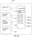
- Fig. 2b shows, by way of example, a block diagram of the control unit of the monitoring apparatus.
- the monitoring apparatus comprises the control unit 200.
- the control unit 200 may comprise memory MEM.
- the control unit 200 may comprise computer program code PROG residing in the memory MEM for implementing, for example, monitoring electricity supply.
- the control unit 200 may comprise one or more processors PROC1, PROC2 that, when running the computer program code PROG, causes the monitoring apparatus to carry out the method as disclosed herein.
- the control unit 200 may comprise communication modules COMM1, COMM2 for communicating with other devices.
- the control unit 200 may comprise circuitry and electronics for handling, receiving and transmitting data.
- the control unit 200 may comprise or may be connected to these elements, or fewer or more elements. The elements of the control unit 200 may be connected with each other.
- the monitoring apparatus comprises a sensor unit 210 for detecting electric field in the power cord.
- the sensor may be configured to monitor voltage in the electricity supply means of the device, e.g. beverage cooler.
- the electricity supply means is a power cord.
- the sensor is configured to detect a loss of voltage.
- a magnetic field is produced around a power cord (conductor) carrying a current. If the current is alternating current, the magnetic field produced around the power cord varies periodically.
- the sensor 210 may comprise e.g. one or more transistors for detecting the changing magnetic field.
- the transistor may be e.g. a NPN type transistor.
- the sensor may comprise an antenna 211 (see Fig. 2a ).
- a current will be induced into the antenna from the power cord carrying the current due to electromagnetic induction.
- the antenna is connected to the transistor and the current triggers the transistor on. If the electricity in the power cord is cut off, the transistor is triggered off.
- the transistor may act as a switch.
- the antenna 211 may function as a spring for producing a compressive force against the power cord 150. Size, i.e. diameter of the power cord may vary, and the compressive force of the spring helps to prevent the sliding of the monitoring apparatus along the power cord.
- the electricity in the power cord may be cut off.
- the electricity in the power cord may be cut off e.g. because of a power failure or if the power cord is removed from a power socket.
- the sensor 210 may detect a loss of voltage. The loss of voltage may be detected if the monitoring apparatus 100 is removed from the power cord. Indication that the loss of voltage has been detected may be stored in the memory MEM.
- the monitoring apparatus 100 may comprise a switch 240.
- the switch may be a tampering switch.
- the control unit 220 may be connected to or comprise the tampering switch 240.
- the tampering switch may be a micro switch i.e. a miniature snap-action switch.
- the micro switch is an electric switch that is actuated by small physical force through the use of a tipping-point mechanism.
- the tampering switch may detect if the cover 110, 120 of the monitoring apparatus 100 is opened or closed. If the cover 110, 120 of the monitoring apparatus 100 is opened and/or the monitoring apparatus is removed from the power cord 150, loss of voltage may be detected.
- the status of the tampering switch may be read and stored in the memory MEM. The status of the tampering switch may be reported as a part of a status message as described below.
- the monitoring apparatus may be configured to operate in a monitoring state and in an active state.
- the sensor unit is detecting voltage.
- Current consumption of the monitoring apparatus during the monitoring state is estimated to be low, approximately 10 ⁇ A in average. Thus, the use of the monitoring apparatus is environmentally friendly. If the loss of voltage occurs, the monitoring apparatus is configured to operate in the active state, which is described below.
- beverage coolers In addition to monitoring the supply of electricity of beverage coolers, it is beneficial to know location of the cooler which is out of electricity and/or the monitoring apparatus of which has been opened. Beverage coolers in restaurants or cafés are usually provided by a beverage distributor without direct costs. If a restaurant or a café closes its business, the beverage cooler may be e.g. given to someone or may get lost for some other reason. If the beverage cooler ends up to environment, it will be harmful for the nature.
- the monitoring apparatus comprises a positioning module 220.
- the control unit 200 may be connected to or may comprise the positioning module 220. If the loss of voltage has occurred, the positioning module 220 is configured to activate in response to the detected loss of voltage. Activating means that the positioning module is powered up. If the positioning module is already powered up, the activating means that the positioning module is requested to acquire positioning information.
- the sensor 210 may switch the positioning module on in response to the detected loss of voltage. When the positioning module is switched on, the monitoring apparatus is in the active state. Since the positioning module is powered off, i.e. in a sleep mode, during monitoring state when there is no loss of voltage detected, the power consumption of the monitoring apparatus may be decreased. The loss of voltage may trigger the powering up of the positioning module.
- the positioning module may be activated in a certain time after the loss of voltage has been detected if the loss of voltage is still detected after the certain time. This is beneficial, since a short and unharmful power failure may occur, and it may be unnecessary to activate the positioning module if the voltage is restored shortly.
- the certain time i.e. delay may be determined by a user. The delay may be provided through a user interface as an input.
- the positioning module When the positioning module is activated, the positioning module is configured to acquire positioning information of the monitoring apparatus.
- the positioning information may be acquired e.g. using network-based techniques and/or satellite navigation systems, such as GPS, Galileo or GLONASS.
- the positioning information may be acquired using e.g. triangulation or multilateration. Triangulation is a process of determining a location of a point by forming triangles to it from known points, e.g. three known base stations. Coordinates (latitude and longitude) of the beverage cooler may be determined using the positioning information.
- self-reported positioning may be used such that the user determines the position of the beverage cooler when installing the monitoring apparatus over the power cord of the beverage cooler.
- the user may provide the original installation position as an input to the monitoring apparatus.
- the input may be provided through a user interface.
- the monitoring apparatus may comprise or may be connected to the user interface.
- the user interface may receive user input through a touch screen and/or a keypad.
- the positioning module may be connected to the memory MEM.
- the positioning information may be stored in the memory MEM.
- the positioning information may be acquired from the memory MEM.
- the positioning module may be configured to acquire positioning information at certain time intervals, e.g. once a day or every hour and store the positioning information in the memory MEM.
- the positioning information e.g. the latest acquired positioning information, may be acquired from the memory MEM.
- the positioning module activates and the monitoring apparatus is in active state.
- the monitoring apparatus may provide status information on the monitoring apparatus to a database 810, 820 (see Fig. 3 ).
- the sensor may be active during the active state.
- the monitoring apparatus may comprise a status message generator 230.
- the control unit 200 may be connected to or may comprise the status message generator 230.
- the positioning module may be connected to or may comprise the status message generator.
- the status message generator may receive data from the memory MEM.
- the data may comprise e.g. the positioning information and/or the status of the tampering switch and/or information that the voltage loss has been detected.
- the status message generator may generate the status message based on the data received from the memory MEM.
- the monitoring apparatus may transmit a status message.
- the positioning module is configured to transmit the status message using the communication module COMM1, COMM2.
- the status message may be transmitted to a remote unit.
- the remote unit may be e.g. the database 810, 820 or the user device 900 (see Fig. 3 ).
- the status message comprises at least the positioning information.
- the positioning information may be used to determine which beverage cooler may be out of electric supply.
- the positioning information may be used to determine if
- the status message may comprise a time stamp.
- the time stamp may be UTC time received from a cellular network.
- the time stamp may be stored in the memory MEM.
- the status message may be provided once or the status message may be sent at certain time intervals. Time interval between the message transmissions may be set to e.g. 30 - 60 min. Between the transmissions the positioning module may be powered off. The power consumption may be decreased by keeping the positioning module in the sleep mode between the transmissions.
- the status message may comprise device authentication data.
- the status message may comprise information that the voltage loss has been detected.
- the status message may comprise a reason for the voltage loss.
- the monitoring apparatus may have been removed from the power cord and it may be detected using the tampering switch.
- the tampering switch is arranged to detect if the cover of the monitoring apparatus is opened or closed. If the tampering switch detects that the cover of the monitoring apparatus is opened, it may be determined that the loss of voltage occurred because of the removal of the monitoring apparatus from the power cord. This means that the beverage cooler is not necessarily out of electricity. Using the positioning information it may be determined where the beverage cooler is and the situation of the beverage cooler may be checked out by maintenance personnel.
- the status message may comprise information on battery 250 level of the monitoring apparatus 100 and/or low battery alert.
- the status message may comprise initial installation position of the beverage cooler.
- the status message may comprise indication that the positioning module is powered off to sleep mode.
- the monitoring apparatus may acquire positioning information of the monitoring apparatus and transmit the status message comprising at least the positioning information to the remote unit.
- the positioning module may be deactivated in response to the transmitting of the status message. Deactivating means that the positioning module is powered off. The powering off may be triggered by the providing of the status message. This may ensure that sending of the status message is carried out before the positioning module is powered off.
- the status message may comprise the data described above.
- the status message may comprise indication that the voltage is detected i.e. restored.
- the status message may comprise indication that the positioning module is powered off to sleep mode.
- the power consumption may be decreased by returning the positioning module into sleep mode.
- a time delay e.g. of half an hour, or 1 hour, may be set for deactivation. This means that after the restoration of voltage has been detected, the device may be in active state for 1 hour before returning to the monitoring state.
- Fig. 3 shows, by way of example, a system for monitoring electricity supply.
- the system may be a service system for monitoring and keeping track of beverage coolers.
- the system comprises one or more voltage detection means.
- the voltage detection means may comprise, for example, the sensor unit in the monitoring apparatus 100, 300, 400.
- the electricity supply means 150, 350, 450, e.g. the power cord, of the devices 500, 600, 700 may be provided with the voltage detection means.
- the one or more monitoring apparatus 100, 300, 400 are attached over the power cords of the devices 500, 600, 700.
- the device 500, 600, 700 may be e.g. a beverage cooler or a freezer.
- the one or more monitoring apparatus 100, 300, 400 may be connected through a communication connection to a network 800, e.g.
- the communication connection may be e.g. a wireless cellular communication network or a wireless local area network.
- the system may comprise one or more databases 810, 820. The databases may be connected through a communication connection to the network 800.
- the database 810, 820 may be implemented in one or more servers and together they may form a server system such as a cloud.
- the database 810, 820 may receive positioning information and/or status message(s) from the monitoring apparatus 100, 300, 400.
- the system may comprise a user device 900.
- the user device 900 may be connected through a communication connection to the network 800.
- the user device may comprise the user interface of the monitoring apparatus.
- the user device may be e.g. a personal computer or a smartphone.
- the user device 900 may receive the positioning information and/or status message(s) from the database and/or the user device 900 may be used to access the positioning information and/or status message(s) in the database.
- the monitoring apparatuses 100, 300, 400 may be paired with corresponding devices 500, 600, 700.
- the pairing may be carried out e.g. by scanning a bar code from the monitoring apparatus and entering details of the device to the service system using the user device 900. Details may comprise e.g. a serial number of a beverage cooler, model of the beverage cooler and/or a name of the possessor of the beverage cooler and/or a user responsible of the maintenance of the beverage cooler.
- the positioning module When installing the monitoring apparatus 100 over the power cord of the device for the first time, the positioning module may be powered on and configured to acquire positioning information and to provide the original installation position of the device to the service system. After sending at least the original installation position to the service system, the positioning module may be powered off to sleep mode.
- the remote unit is configured to receive the status message(s) from the monitoring apparatus 100, 300, 400.
- the status message comprises at least the positioning information of the monitoring apparatus.
- the remote unit is configured to determine based on the positioning information that loss of voltage has occurred in the power cord of the device 500, 600, 700.
- the remote unit may be configured to form a map showing a location of the monitoring apparatus based on the positioning information.
- the map (without location information of the monitoring apparatuses) may be a digital map received from a web mapping service, e.g. Bing ® Maps or Google ® Maps. Web mapping is a process of using maps delivered by geographic information systems (GIS).
- the remote unit may be configured to show the formed map showing location(s) of the monitoring apparatus(es) to the user, e.g. the maintenance personnel and/or the owner of the device 500, 600, 700.
- the map may be showed e.g. on a screen of the user device 900.
- the view on the map may be modified according to needs of the user. It may be selected to show on the map e.g. the devices that have been moved from the original installation location, the devices with which a voltage loss has occurred, the devices with low battery status, the devices that have reported tampering, or all the devices in the service system. At least part of the information received in the status message(s) may be delivered to the user e.g. the maintenance personnel and/or the owner of the device. The information may be delivered e.g. as a text message, e-mail, or as an automated phone call.
- the beverage cooler may have been returned to a warehouse of the owner.
- the device may be unpaired from the monitoring apparatus.
- the device and the monitoring apparatus may be unpaired automatically, if it is determined based on the received positioning information that the monitoring apparatus is located in the warehouse or at the proximity of the warehouse.
- the proximity settings may be defined by the user.
- Fig. 4 shows, by way of example, a block diagram of the monitoring apparatus 100, the databases 810, 820, and/or the user device 900.
- the monitoring apparatus, the databases 810, 820, and/or the user device 900 may comprise memory MEM.
- the monitoring apparatus, the databases 810, 820, and/or the user device 900 may comprise computer program code PROG residing in the memory MEM for implementing, for example, monitoring electricity supply.
- the monitoring apparatus, the databases 810, 820, and/or the user device 900 may comprise one or more processors PROC1, PROC2 that, when running the computer program code PROG, causes the apparatuses to carry out the method(s) as disclosed herein.
- the monitoring apparatus, the databases 810, 820, and/or the user device 900 may comprise communication modules COMM1, COMM2 for communicating with other devices.
- the monitoring apparatus, the databases 810, 820, and/or the user device 900 may comprise circuitry and electronics for handling, receiving and transmitting data.
- the monitoring apparatus, the databases 810, 820, and/or the user device 900 may comprise these elements, or fewer or more elements.
- Fig. 5 shows, by way of example, a method for monitoring electricity supply.
- the method comprises providing 910 an electricity supply means of a device with a voltage detection means, monitoring 920 voltage in the electricity supply means, detecting loss of voltage, activating 930, in response to the detected loss of voltage, a positioning module, acquiring 940 a first positioning information of the voltage detection means.
- the positioning information acquired in response to the detected loss of voltage is the first positioning information.
- the method further comprises transmitting 950 a first status message comprising at least the first positioning information to a remote unit.
- the status message transmitted in response to the detected loss of voltage is the first status message.
- the method may comprise detecting restoration of voltage.
- the method may comprise acquiring, in response to the detected restoration of voltage, a second positioning information of the voltage detection means.
- the positioning information acquired in response to the detected restoration of voltage is the second positioning information.
- the first positioning information may be the same as the second positioning information if the monitoring apparatus has not been moved.
- the method may comprise transmitting a second status message comprising at least the second positioning information to the remote unit.
- the status message transmitted in response to the restoration of voltage is the second status message.
- the method may comprise deactivating, in response to the transmitting of the second status message, the positioning module.
- Fig. 6 shows, by way of example, a method for monitoring electricity supply.
- the method comprises receiving 1010 a status message comprising at least a positioning information of a voltage detection means monitoring voltage in an electricity supply means of a device, determining 1020 based on the positioning information that loss of voltage has occurred in the electricity supply means of the device, and delivering 1030 the positioning information of the device to a user.
Landscapes
- Engineering & Computer Science (AREA)
- Physics & Mathematics (AREA)
- Power Engineering (AREA)
- General Physics & Mathematics (AREA)
- Mechanical Engineering (AREA)
- Combustion & Propulsion (AREA)
- Chemical & Material Sciences (AREA)
- Thermal Sciences (AREA)
- General Engineering & Computer Science (AREA)
- Telephonic Communication Services (AREA)
- Testing Electric Properties And Detecting Electric Faults (AREA)
- Protection Of Static Devices (AREA)
- Measurement Of Current Or Voltage (AREA)
- Secondary Cells (AREA)
- Remote Monitoring And Control Of Power-Distribution Networks (AREA)
Description
- Various devices, such as refrigerators, freezers and coolers, use electricity. Supply of electricity may be interrupted for various reasons. There is, therefore, a need for monitoring the supply of electricity.
-
US2013335223 discloses a method and a system of deterring theft of an electronic device connected to an external source of charging power. Electronic device includes theft deterrent program, embedded controller, power controller, main battery, and backup power DC source 180. While the electronic device is armed, the electronic device detects loss of the connection to the source of charging power, and in response, the electronic device activates an alarm or notifies another computing device that the electronic device has been disconnected from the source of charging power. - Various aspects of the invention include an apparatus and a system, and a computer readable medium comprising a computer program stored therein, which are characterized by what is stated in the independent claims. Various embodiments of the invention are disclosed in the dependent claims.
- In the following, various embodiments of the invention will be described in more detail with reference to the appended drawings, in which
- Fig. 1
- shows, by way of example, an apparatus for monitoring electricity supply;
- Fig. 2a
- shows, by way of example, an apparatus for monitoring electricity supply;
- Fig. 2b
- shows, by way of example, a block diagram of a control unit of an apparatus for monitoring electricity supply;
- Fig. 3
- shows, by way of example, a system for monitoring electricity supply;
- Fig. 4
- shows, by way of example, a block diagram of a monitoring apparatus;
- Fig. 5
- shows, by way of example, a method for monitoring electricity supply; and
- Fig. 6
- shows, by way of example, a method for monitoring electricity supply,
- The drawings are schematic.
- In the following, several embodiments of the invention will be described in the context of beverage coolers. It is to be noted, however, that the invention is not limited to beverage coolers. In fact, the different embodiments have applications in any environment where monitoring the supply of electricity is required.
-
Fig. 1 shows, by way of example, an apparatus for monitoring electricity supply. Themonitoring apparatus 100 is a voltage detection means installed over apower cord 150. - The
power cord 150 may be a power cord of any equipment, e.g. a cooler equipment such as a freezer or a refrigerator. Installation of themonitoring apparatus 100 may be carried out by a person not having any specific qualification of electrician or equivalent. Themonitoring apparatus 100 need not have any galvanic connection to the electric parts of thepower cord 150. Themonitoring apparatus 100 may be installed such that it surrounds thepower cord 150. The installation may be tight enough such that themonitoring apparatus 100 does not slide along thepower cord 150. -
Fig. 2a shows, by way of example, the apparatus for monitoring electricity supply. Themonitoring apparatus 100 may have atop cover 110 and abottom cover 120. Thetop cover 110 and thebottom cover 120 may be hingedly attached to each other. In a closed position, such as inFig. 1 , themonitoring apparatus 100 may have a form of cylinder. Alternatively, the form of the monitoring apparatus may be e.g. spherical or prism. Thetop cover 110 and thebottom cover 120 form a chamber when the covers are in the closed position. The formed chamber is a hollow space wherein e.g. acontrol unit 200 and one ormore battery 250 may be assembled. The monitoring apparatus may comprise one ormore battery 250 for supplying power to e.g. asensor unit 210 and/or to apositioning module 220. Thetop cover 110 and thebottom cover 120 may haveopenings power cord 150. The power cord may be squeezed between the openings such that themonitoring apparatus 100 does not slide along thepower cord 150. -
Fig. 2b shows, by way of example, a block diagram of the control unit of the monitoring apparatus. The monitoring apparatus comprises thecontrol unit 200. Thecontrol unit 200 may comprise memory MEM. Thecontrol unit 200 may comprise computer program code PROG residing in the memory MEM for implementing, for example, monitoring electricity supply. Thecontrol unit 200 may comprise one or more processors PROC1, PROC2 that, when running the computer program code PROG, causes the monitoring apparatus to carry out the method as disclosed herein. Thecontrol unit 200 may comprise communication modules COMM1, COMM2 for communicating with other devices. Thecontrol unit 200 may comprise circuitry and electronics for handling, receiving and transmitting data. Thecontrol unit 200 may comprise or may be connected to these elements, or fewer or more elements. The elements of thecontrol unit 200 may be connected with each other. - The monitoring apparatus comprises a
sensor unit 210 for detecting electric field in the power cord. The sensor may be configured to monitor voltage in the electricity supply means of the device, e.g. beverage cooler. The electricity supply means is a power cord. The sensor is configured to detect a loss of voltage. A magnetic field is produced around a power cord (conductor) carrying a current. If the current is alternating current, the magnetic field produced around the power cord varies periodically. Thesensor 210 may comprise e.g. one or more transistors for detecting the changing magnetic field. The transistor may be e.g. a NPN type transistor. The sensor may comprise an antenna 211 (seeFig. 2a ). A current will be induced into the antenna from the power cord carrying the current due to electromagnetic induction. The antenna is connected to the transistor and the current triggers the transistor on. If the electricity in the power cord is cut off, the transistor is triggered off. The transistor may act as a switch. - The
antenna 211 may function as a spring for producing a compressive force against thepower cord 150. Size, i.e. diameter of the power cord may vary, and the compressive force of the spring helps to prevent the sliding of the monitoring apparatus along the power cord. - There may be situations where the electricity in the power cord is cut off. The electricity in the power cord may be cut off e.g. because of a power failure or if the power cord is removed from a power socket. The
sensor 210 may detect a loss of voltage. The loss of voltage may be detected if themonitoring apparatus 100 is removed from the power cord. Indication that the loss of voltage has been detected may be stored in the memory MEM. - The
monitoring apparatus 100 may comprise aswitch 240. The switch may be a tampering switch. Thecontrol unit 220 may be connected to or comprise thetampering switch 240. The tampering switch may be a micro switch i.e. a miniature snap-action switch. The micro switch is an electric switch that is actuated by small physical force through the use of a tipping-point mechanism. The tampering switch may detect if thecover monitoring apparatus 100 is opened or closed. If thecover monitoring apparatus 100 is opened and/or the monitoring apparatus is removed from thepower cord 150, loss of voltage may be detected. The status of the tampering switch may be read and stored in the memory MEM. The status of the tampering switch may be reported as a part of a status message as described below. - The monitoring apparatus may be configured to operate in a monitoring state and in an active state. During the monitoring state the sensor unit is detecting voltage. Current consumption of the monitoring apparatus during the monitoring state is estimated to be low, approximately 10µA in average. Thus, the use of the monitoring apparatus is environmentally friendly. If the loss of voltage occurs, the monitoring apparatus is configured to operate in the active state, which is described below.
- In addition to monitoring the supply of electricity of beverage coolers, it is beneficial to know location of the cooler which is out of electricity and/or the monitoring apparatus of which has been opened. Beverage coolers in restaurants or cafés are usually provided by a beverage distributor without direct costs. If a restaurant or a café closes its business, the beverage cooler may be e.g. given to someone or may get lost for some other reason. If the beverage cooler ends up to environment, it will be harmful for the nature.
- The monitoring apparatus comprises a
positioning module 220. Thecontrol unit 200 may be connected to or may comprise thepositioning module 220. If the loss of voltage has occurred, thepositioning module 220 is configured to activate in response to the detected loss of voltage. Activating means that the positioning module is powered up. If the positioning module is already powered up, the activating means that the positioning module is requested to acquire positioning information. Thesensor 210 may switch the positioning module on in response to the detected loss of voltage. When the positioning module is switched on, the monitoring apparatus is in the active state. Since the positioning module is powered off, i.e. in a sleep mode, during monitoring state when there is no loss of voltage detected, the power consumption of the monitoring apparatus may be decreased. The loss of voltage may trigger the powering up of the positioning module. - The positioning module may be activated in a certain time after the loss of voltage has been detected if the loss of voltage is still detected after the certain time. This is beneficial, since a short and unharmful power failure may occur, and it may be unnecessary to activate the positioning module if the voltage is restored shortly. The certain time i.e. delay may be determined by a user. The delay may be provided through a user interface as an input.
- When the positioning module is activated, the positioning module is configured to acquire positioning information of the monitoring apparatus. The positioning information may be acquired e.g. using network-based techniques and/or satellite navigation systems, such as GPS, Galileo or GLONASS. The positioning information may be acquired using e.g. triangulation or multilateration. Triangulation is a process of determining a location of a point by forming triangles to it from known points, e.g. three known base stations. Coordinates (latitude and longitude) of the beverage cooler may be determined using the positioning information. Alternatively or in addition, self-reported positioning may be used such that the user determines the position of the beverage cooler when installing the monitoring apparatus over the power cord of the beverage cooler. The user may provide the original installation position as an input to the monitoring apparatus. The input may be provided through a user interface. The monitoring apparatus may comprise or may be connected to the user interface. The user interface may receive user input through a touch screen and/or a keypad. The positioning module may be connected to the memory MEM. The positioning information may be stored in the memory MEM.
- Alternatively or in addition to the network based techniques described above, the positioning information may be acquired from the memory MEM. The positioning module may be configured to acquire positioning information at certain time intervals, e.g. once a day or every hour and store the positioning information in the memory MEM. When the positioning module activates, the positioning information, e.g. the latest acquired positioning information, may be acquired from the memory MEM.
- When the loss of voltage occurs and is detected, the positioning module activates and the monitoring apparatus is in active state. During the active state the monitoring apparatus may provide status information on the monitoring apparatus to a
database 810, 820 (seeFig. 3 ). The sensor may be active during the active state. - The monitoring apparatus may comprise a
status message generator 230. Thecontrol unit 200 may be connected to or may comprise thestatus message generator 230. The positioning module may be connected to or may comprise the status message generator. The status message generator may receive data from the memory MEM. The data may comprise e.g. the positioning information and/or the status of the tampering switch and/or information that the voltage loss has been detected. The status message generator may generate the status message based on the data received from the memory MEM. The monitoring apparatus may transmit a status message. The positioning module is configured to transmit the status message using the communication module COMM1, COMM2. The status message may be transmitted to a remote unit. The remote unit may be e.g. thedatabase Fig. 3 ). The status message comprises at least the positioning information. The positioning information may be used to determine which beverage cooler may be out of electric supply. The positioning information may be used to determine if the beverage cooler is moved from its location, e.g. stolen. - The status message may comprise a time stamp. The time stamp may be UTC time received from a cellular network. The time stamp may be stored in the memory MEM.
- The status message may be provided once or the status message may be sent at certain time intervals. Time interval between the message transmissions may be set to e.g. 30 - 60 min. Between the transmissions the positioning module may be powered off. The power consumption may be decreased by keeping the positioning module in the sleep mode between the transmissions.
- The status message may comprise device authentication data. The status message may comprise information that the voltage loss has been detected. The status message may comprise a reason for the voltage loss. For example, the monitoring apparatus may have been removed from the power cord and it may be detected using the tampering switch. The tampering switch is arranged to detect if the cover of the monitoring apparatus is opened or closed. If the tampering switch detects that the cover of the monitoring apparatus is opened, it may be determined that the loss of voltage occurred because of the removal of the monitoring apparatus from the power cord. This means that the beverage cooler is not necessarily out of electricity. Using the positioning information it may be determined where the beverage cooler is and the situation of the beverage cooler may be checked out by maintenance personnel. The status message may comprise information on
battery 250 level of themonitoring apparatus 100 and/or low battery alert. The status message may comprise initial installation position of the beverage cooler. The status message may comprise indication that the positioning module is powered off to sleep mode. - If the cause of the detected voltage loss is removed and restoration of voltage is detected by the monitoring apparatus, the monitoring apparatus may acquire positioning information of the monitoring apparatus and transmit the status message comprising at least the positioning information to the remote unit. When the status message has been transmitted to the remote unit which saves it in the database, the positioning module may be deactivated in response to the transmitting of the status message. Deactivating means that the positioning module is powered off. The powering off may be triggered by the providing of the status message. This may ensure that sending of the status message is carried out before the positioning module is powered off. The status message may comprise the data described above. The status message may comprise indication that the voltage is detected i.e. restored. The status message may comprise indication that the positioning module is powered off to sleep mode. The power consumption may be decreased by returning the positioning module into sleep mode. A time delay, e.g. of half an hour, or 1 hour, may be set for deactivation. This means that after the restoration of voltage has been detected, the device may be in active state for 1 hour before returning to the monitoring state.
-
Fig. 3 shows, by way of example, a system for monitoring electricity supply. The system may be a service system for monitoring and keeping track of beverage coolers. The system comprises one or more voltage detection means. The voltage detection means may comprise, for example, the sensor unit in themonitoring apparatus devices more monitoring apparatus devices device more monitoring apparatus network 800, e.g. a cellular network or Internet. The communication connection may be e.g. a wireless cellular communication network or a wireless local area network. The system may comprise one ormore databases network 800. Thedatabase database monitoring apparatus user device 900. Theuser device 900 may be connected through a communication connection to thenetwork 800. The user device may comprise the user interface of the monitoring apparatus. The user device may be e.g. a personal computer or a smartphone. Theuser device 900 may receive the positioning information and/or status message(s) from the database and/or theuser device 900 may be used to access the positioning information and/or status message(s) in the database. - When the
devices apparatuses corresponding devices user device 900. Details may comprise e.g. a serial number of a beverage cooler, model of the beverage cooler and/or a name of the possessor of the beverage cooler and/or a user responsible of the maintenance of the beverage cooler. - When installing the
monitoring apparatus 100 over the power cord of the device for the first time, the positioning module may be powered on and configured to acquire positioning information and to provide the original installation position of the device to the service system. After sending at least the original installation position to the service system, the positioning module may be powered off to sleep mode. - The remote unit is configured to receive the status message(s) from the
monitoring apparatus device device user device 900. - The view on the map may be modified according to needs of the user. It may be selected to show on the map e.g. the devices that have been moved from the original installation location, the devices with which a voltage loss has occurred, the devices with low battery status, the devices that have reported tampering, or all the devices in the service system. At least part of the information received in the status message(s) may be delivered to the user e.g. the maintenance personnel and/or the owner of the device. The information may be delivered e.g. as a text message, e-mail, or as an automated phone call.
- It is possible to remove a device from the service system. For example, the beverage cooler may have been returned to a warehouse of the owner. The device may be unpaired from the monitoring apparatus. The device and the monitoring apparatus may be unpaired automatically, if it is determined based on the received positioning information that the monitoring apparatus is located in the warehouse or at the proximity of the warehouse. The proximity settings may be defined by the user.
-
Fig. 4 shows, by way of example, a block diagram of themonitoring apparatus 100, thedatabases user device 900. The monitoring apparatus, thedatabases user device 900 may comprise memory MEM. The monitoring apparatus, thedatabases user device 900 may comprise computer program code PROG residing in the memory MEM for implementing, for example, monitoring electricity supply. The monitoring apparatus, thedatabases user device 900 may comprise one or more processors PROC1, PROC2 that, when running the computer program code PROG, causes the apparatuses to carry out the method(s) as disclosed herein. The monitoring apparatus, thedatabases user device 900 may comprise communication modules COMM1, COMM2 for communicating with other devices. The monitoring apparatus, thedatabases user device 900 may comprise circuitry and electronics for handling, receiving and transmitting data. The monitoring apparatus, thedatabases user device 900 may comprise these elements, or fewer or more elements. -
Fig. 5 shows, by way of example, a method for monitoring electricity supply. The method comprises providing 910 an electricity supply means of a device with a voltage detection means, monitoring 920 voltage in the electricity supply means, detecting loss of voltage, activating 930, in response to the detected loss of voltage, a positioning module, acquiring 940 a first positioning information of the voltage detection means. The positioning information acquired in response to the detected loss of voltage is the first positioning information. The method further comprises transmitting 950 a first status message comprising at least the first positioning information to a remote unit. The status message transmitted in response to the detected loss of voltage is the first status message. - According to an embodiment, the method may comprise detecting restoration of voltage. The method may comprise acquiring, in response to the detected restoration of voltage, a second positioning information of the voltage detection means. The positioning information acquired in response to the detected restoration of voltage is the second positioning information. The first positioning information may be the same as the second positioning information if the monitoring apparatus has not been moved. The method may comprise transmitting a second status message comprising at least the second positioning information to the remote unit. The status message transmitted in response to the restoration of voltage is the second status message. The method may comprise deactivating, in response to the transmitting of the second status message, the positioning module.
-
Fig. 6 shows, by way of example, a method for monitoring electricity supply. The method comprises receiving 1010 a status message comprising at least a positioning information of a voltage detection means monitoring voltage in an electricity supply means of a device, determining 1020 based on the positioning information that loss of voltage has occurred in the electricity supply means of the device, and delivering 1030 the positioning information of the device to a user. - It is obvious that the present invention is not limited solely to the above-presented embodiments, but it can be modified within the scope of the appended claims.
Claims (6)
- An apparatus (100), installable over a power cord of a device, comprising:a sensor unit (210) configured to monitor voltage in the power cord (150) of the device (500) and to detect loss of voltage in the power cord;a positioning module (220) configured tobe in a sleep mode when the voltage in the power cord is monitored;activate in response to the detected loss of voltage;acquire a first positioning information of the apparatus (100); andtransmit a first status message comprising at least the first positioning information to a remote unit (810).
- The apparatus (100) according to claim 1, whereinthe sensor unit (210) is further configured to detect restoration of voltage in the power cord;the positioning module (220) is further configured toacquire, in response to the detected restoration of voltage, a second positioning information of the apparatus (100);transmit a second status message comprising at least the second positioning information to the remote unit (810);deactivate, in response to the transmitting of the second status message, the positioning module (220).
- The apparatus (100) according to claim 1 or 2, further comprising a cover (110);
a switch (240) configured to detect if the cover (110) of the apparatus (100) is open; and wherein the positioning module (220) is further configured to include in the first status message information that the cover (110) is open. - A system comprisingat least one apparatus (100, 300, 400) of any of the claims 1 to 3; anda remote unit (810) in a communication connection with the at least one apparatus (100, 300, 400), the remote unit (810) comprising at least one processor, memory including computer program code, the memory and the computer program code configured to, with the at least one processor, cause the remote unit toreceive a status message comprising at least the positioning information of the at least one voltage detection means (100, 300, 400);characterized in that the remote unit is further caused to determine based on the positioning information that loss of voltage has occurred in the power cord (150, 350, 450) of the device (500, 600, 700); anddeliver the positioning information of the device to a user.
- A computer program product embodied on a non-transitory computer readable medium, comprising computer program code configured to, when executed on at least one processor, cause an apparatus of any of the claims 1 to 3 to perform:monitoring, by a sensor unit (210), voltage in the power cord (150) of the device (500) and detecting loss of voltage in the power cord;causing the positioning module (220) to:be in a sleep mode when the voltage in the power cord is monitored;activate in response to detected loss of voltage;acquire a first positioning information of the apparatus (100); andtransmit a first status message comprising at least the first positioning information to a remote unit (810).
- A computer program product embodied on a non-transitory computer readable medium, comprising computer program code configured to, when executed on at least one processor, cause a system of claim 4 to perform:receive, by the remote unit, a status message comprising at least the positioning information of the at least one voltage detection means (100, 300, 400);characterized in that the system is configured to perform: monitoring, by a sensor unit (210), voltage in the power cord (150, 350, 450) of the device (500, 600, 700) and detecting loss of voltage in the power cord;causing the positioning module tobe in a sleep mode when the voltage in the power cord is monitored;activate in response to detected loss of voltage;acquire a first positioning information of the apparatus (100); andtransmit a first status message comprising at least the first positioning information to the remote unit (810); and in that the system is caused to perform:determining, by the remote unit, based on the positioning information that loss of voltage has occurred in the power cord (150, 350, 450) of the device (500, 600, 700); anddelivering the positioning information of the device to a user.
Applications Claiming Priority (2)
| Application Number | Priority Date | Filing Date | Title |
|---|---|---|---|
| FI20175307A FI128017B (en) | 2017-04-03 | 2017-04-03 | Method and apparatus for controlling power supply |
| PCT/FI2018/050222 WO2018185365A1 (en) | 2017-04-03 | 2018-03-23 | Method and apparatus for monitoring supply of electricity |
Publications (3)
| Publication Number | Publication Date |
|---|---|
| EP3607634A1 EP3607634A1 (en) | 2020-02-12 |
| EP3607634A4 EP3607634A4 (en) | 2021-01-06 |
| EP3607634B1 true EP3607634B1 (en) | 2023-06-07 |
Family
ID=63712047
Family Applications (1)
| Application Number | Title | Priority Date | Filing Date |
|---|---|---|---|
| EP18780937.1A Active EP3607634B1 (en) | 2017-04-03 | 2018-03-23 | Method and apparatus for monitoring supply of electricity |
Country Status (3)
| Country | Link |
|---|---|
| EP (1) | EP3607634B1 (en) |
| FI (1) | FI128017B (en) |
| WO (1) | WO2018185365A1 (en) |
Families Citing this family (1)
| Publication number | Priority date | Publication date | Assignee | Title |
|---|---|---|---|---|
| US12287357B2 (en) | 2023-06-23 | 2025-04-29 | John C. Atherton | Power cord voltage indicator |
Family Cites Families (5)
| Publication number | Priority date | Publication date | Assignee | Title |
|---|---|---|---|---|
| DE102006029427A1 (en) * | 2006-06-27 | 2008-01-03 | Wolf-Dieter Freyhann | Charger for e.g. mobile telephone, has alarm function, which is switched on or off by code, where alarm is triggered, when socket and terminal of cable of charger are disconnected independent of whether charging process is completed or not |
| US7893686B1 (en) * | 2008-06-05 | 2011-02-22 | Atherton John C | Power cord voltage indicator |
| JP4735728B2 (en) * | 2009-03-05 | 2011-07-27 | 株式会社デンソー | In-vehicle wireless communication device |
| US20130335223A1 (en) | 2012-06-18 | 2013-12-19 | International Business Machines Corporation | Electronics theft deterrent system |
| US9910102B2 (en) * | 2014-11-20 | 2018-03-06 | Abb Schweiz Ag | Methods, systems, and computer readable media for monitoring and management of a power distribution system |
-
2017
- 2017-04-03 FI FI20175307A patent/FI128017B/en active IP Right Grant
-
2018
- 2018-03-23 WO PCT/FI2018/050222 patent/WO2018185365A1/en not_active Ceased
- 2018-03-23 EP EP18780937.1A patent/EP3607634B1/en active Active
Also Published As
| Publication number | Publication date |
|---|---|
| FI20175307A7 (en) | 2018-10-04 |
| FI128017B (en) | 2019-08-15 |
| EP3607634A4 (en) | 2021-01-06 |
| FI20175307L (en) | 2018-10-04 |
| EP3607634A1 (en) | 2020-02-12 |
| WO2018185365A1 (en) | 2018-10-11 |
Similar Documents
| Publication | Publication Date | Title |
|---|---|---|
| EP2827168B1 (en) | Object location acquiring system and location acquiring method thereof | |
| US10101431B2 (en) | Systems and methods for pursuit governance in a monitoring system | |
| US11595784B2 (en) | Monitoring objects capable of wireless communications | |
| US6801853B2 (en) | Portable motion-activated position reporting device | |
| US20070290923A1 (en) | Relating to mobile location devices and methods | |
| US20160373893A1 (en) | Ibeacon compatible bluetooth low energy device monitoring system | |
| CN101719304A (en) | Personnel belongings monitoring system based mobile phone Bluetooth | |
| US10068462B2 (en) | Systems and methods for manual tamper reset in a monitoring system | |
| EP3607634B1 (en) | Method and apparatus for monitoring supply of electricity | |
| US11393307B2 (en) | Integrated battery monitoring circuit | |
| Girinath et al. | IoT based threat detection and location tracking for women safety | |
| CN106585560A (en) | Method and equipment for prevention of car burglary | |
| US11263881B2 (en) | System and method of alternative tracking upon disabling of monitoring device | |
| US10673284B2 (en) | Fail safe blocks | |
| EP2889578B1 (en) | Indoor system for providing navigation data | |
| US10529208B2 (en) | Device tracking systems and methods | |
| JP6541189B2 (en) | Transmitter and search system | |
| CN111416859A (en) | Monitoring method, monitoring equipment and computer readable storage medium | |
| US20140159883A1 (en) | Intrusion and theft alert device remotely armed and disarmed by mobile platform application | |
| Handayani et al. | Alert, monitoring and tracking for electronic device prototype | |
| KR20190057046A (en) | Method and apparatus for localizing faults in a power distribution system | |
| GB2523683A (en) | Personal location monitoring device and system | |
| US20230267813A1 (en) | Systems and Methods for Locating Discarded Tracking Devices | |
| CN105578415A (en) | Geographic location information based owner identification and monitoring method | |
| US10972875B2 (en) | System and method of alternative tracking upon disabling of monitoring device |
Legal Events
| Date | Code | Title | Description |
|---|---|---|---|
| STAA | Information on the status of an ep patent application or granted ep patent |
Free format text: STATUS: THE INTERNATIONAL PUBLICATION HAS BEEN MADE |
|
| PUAI | Public reference made under article 153(3) epc to a published international application that has entered the european phase |
Free format text: ORIGINAL CODE: 0009012 |
|
| STAA | Information on the status of an ep patent application or granted ep patent |
Free format text: STATUS: REQUEST FOR EXAMINATION WAS MADE |
|
| 17P | Request for examination filed |
Effective date: 20191101 |
|
| AK | Designated contracting states |
Kind code of ref document: A1 Designated state(s): AL AT BE BG CH CY CZ DE DK EE ES FI FR GB GR HR HU IE IS IT LI LT LU LV MC MK MT NL NO PL PT RO RS SE SI SK SM TR |
|
| AX | Request for extension of the european patent |
Extension state: BA ME |
|
| DAV | Request for validation of the european patent (deleted) | ||
| DAX | Request for extension of the european patent (deleted) | ||
| A4 | Supplementary search report drawn up and despatched |
Effective date: 20201209 |
|
| RIC1 | Information provided on ipc code assigned before grant |
Ipc: F25D 29/00 20060101ALI20201203BHEP Ipc: H02J 13/00 20060101AFI20201203BHEP Ipc: G08C 21/00 20060101ALI20201203BHEP Ipc: G01R 31/08 20200101ALI20201203BHEP |
|
| REG | Reference to a national code |
Ref country code: DE Ref legal event code: R079 Free format text: PREVIOUS MAIN CLASS: H02J0013000000 Ipc: F25D0029000000 Ref country code: DE Ref legal event code: R079 Ref document number: 602018051223 Country of ref document: DE Free format text: PREVIOUS MAIN CLASS: H02J0013000000 Ipc: F25D0029000000 |
|
| RIC1 | Information provided on ipc code assigned before grant |
Ipc: G08B 13/14 20060101ALI20221007BHEP Ipc: G08C 21/00 20060101ALI20221007BHEP Ipc: F25D 29/00 20060101AFI20221007BHEP |
|
| GRAP | Despatch of communication of intention to grant a patent |
Free format text: ORIGINAL CODE: EPIDOSNIGR1 |
|
| STAA | Information on the status of an ep patent application or granted ep patent |
Free format text: STATUS: GRANT OF PATENT IS INTENDED |
|
| INTG | Intention to grant announced |
Effective date: 20221208 |
|
| GRAS | Grant fee paid |
Free format text: ORIGINAL CODE: EPIDOSNIGR3 |
|
| GRAA | (expected) grant |
Free format text: ORIGINAL CODE: 0009210 |
|
| STAA | Information on the status of an ep patent application or granted ep patent |
Free format text: STATUS: THE PATENT HAS BEEN GRANTED |
|
| RAP3 | Party data changed (applicant data changed or rights of an application transferred) |
Owner name: NORDIC 24/7 SERVICES OY |
|
| AK | Designated contracting states |
Kind code of ref document: B1 Designated state(s): AL AT BE BG CH CY CZ DE DK EE ES FI FR GB GR HR HU IE IS IT LI LT LU LV MC MK MT NL NO PL PT RO RS SE SI SK SM TR |
|
| REG | Reference to a national code |
Ref country code: GB Ref legal event code: FG4D |
|
| REG | Reference to a national code |
Ref country code: CH Ref legal event code: EP Ref country code: AT Ref legal event code: REF Ref document number: 1576245 Country of ref document: AT Kind code of ref document: T Effective date: 20230615 Ref country code: DE Ref legal event code: R096 Ref document number: 602018051223 Country of ref document: DE |
|
| P01 | Opt-out of the competence of the unified patent court (upc) registered |
Effective date: 20230527 |
|
| REG | Reference to a national code |
Ref country code: LT Ref legal event code: MG9D |
|
| REG | Reference to a national code |
Ref country code: NL Ref legal event code: MP Effective date: 20230607 |
|
| PG25 | Lapsed in a contracting state [announced via postgrant information from national office to epo] |
Ref country code: SE Free format text: LAPSE BECAUSE OF FAILURE TO SUBMIT A TRANSLATION OF THE DESCRIPTION OR TO PAY THE FEE WITHIN THE PRESCRIBED TIME-LIMIT Effective date: 20230607 Ref country code: NO Free format text: LAPSE BECAUSE OF FAILURE TO SUBMIT A TRANSLATION OF THE DESCRIPTION OR TO PAY THE FEE WITHIN THE PRESCRIBED TIME-LIMIT Effective date: 20230907 Ref country code: ES Free format text: LAPSE BECAUSE OF FAILURE TO SUBMIT A TRANSLATION OF THE DESCRIPTION OR TO PAY THE FEE WITHIN THE PRESCRIBED TIME-LIMIT Effective date: 20230607 |
|
| REG | Reference to a national code |
Ref country code: AT Ref legal event code: MK05 Ref document number: 1576245 Country of ref document: AT Kind code of ref document: T Effective date: 20230607 |
|
| PG25 | Lapsed in a contracting state [announced via postgrant information from national office to epo] |
Ref country code: RS Free format text: LAPSE BECAUSE OF FAILURE TO SUBMIT A TRANSLATION OF THE DESCRIPTION OR TO PAY THE FEE WITHIN THE PRESCRIBED TIME-LIMIT Effective date: 20230607 Ref country code: NL Free format text: LAPSE BECAUSE OF FAILURE TO SUBMIT A TRANSLATION OF THE DESCRIPTION OR TO PAY THE FEE WITHIN THE PRESCRIBED TIME-LIMIT Effective date: 20230607 Ref country code: LV Free format text: LAPSE BECAUSE OF FAILURE TO SUBMIT A TRANSLATION OF THE DESCRIPTION OR TO PAY THE FEE WITHIN THE PRESCRIBED TIME-LIMIT Effective date: 20230607 Ref country code: LT Free format text: LAPSE BECAUSE OF FAILURE TO SUBMIT A TRANSLATION OF THE DESCRIPTION OR TO PAY THE FEE WITHIN THE PRESCRIBED TIME-LIMIT Effective date: 20230607 Ref country code: HR Free format text: LAPSE BECAUSE OF FAILURE TO SUBMIT A TRANSLATION OF THE DESCRIPTION OR TO PAY THE FEE WITHIN THE PRESCRIBED TIME-LIMIT Effective date: 20230607 Ref country code: GR Free format text: LAPSE BECAUSE OF FAILURE TO SUBMIT A TRANSLATION OF THE DESCRIPTION OR TO PAY THE FEE WITHIN THE PRESCRIBED TIME-LIMIT Effective date: 20230908 |
|
| PG25 | Lapsed in a contracting state [announced via postgrant information from national office to epo] |
Ref country code: FI Free format text: LAPSE BECAUSE OF FAILURE TO SUBMIT A TRANSLATION OF THE DESCRIPTION OR TO PAY THE FEE WITHIN THE PRESCRIBED TIME-LIMIT Effective date: 20230607 |
|
| PG25 | Lapsed in a contracting state [announced via postgrant information from national office to epo] |
Ref country code: SK Free format text: LAPSE BECAUSE OF FAILURE TO SUBMIT A TRANSLATION OF THE DESCRIPTION OR TO PAY THE FEE WITHIN THE PRESCRIBED TIME-LIMIT Effective date: 20230607 |
|
| PG25 | Lapsed in a contracting state [announced via postgrant information from national office to epo] |
Ref country code: IS Free format text: LAPSE BECAUSE OF FAILURE TO SUBMIT A TRANSLATION OF THE DESCRIPTION OR TO PAY THE FEE WITHIN THE PRESCRIBED TIME-LIMIT Effective date: 20231007 |
|
| PG25 | Lapsed in a contracting state [announced via postgrant information from national office to epo] |
Ref country code: SM Free format text: LAPSE BECAUSE OF FAILURE TO SUBMIT A TRANSLATION OF THE DESCRIPTION OR TO PAY THE FEE WITHIN THE PRESCRIBED TIME-LIMIT Effective date: 20230607 Ref country code: SK Free format text: LAPSE BECAUSE OF FAILURE TO SUBMIT A TRANSLATION OF THE DESCRIPTION OR TO PAY THE FEE WITHIN THE PRESCRIBED TIME-LIMIT Effective date: 20230607 Ref country code: RO Free format text: LAPSE BECAUSE OF FAILURE TO SUBMIT A TRANSLATION OF THE DESCRIPTION OR TO PAY THE FEE WITHIN THE PRESCRIBED TIME-LIMIT Effective date: 20230607 Ref country code: PT Free format text: LAPSE BECAUSE OF FAILURE TO SUBMIT A TRANSLATION OF THE DESCRIPTION OR TO PAY THE FEE WITHIN THE PRESCRIBED TIME-LIMIT Effective date: 20231009 Ref country code: IS Free format text: LAPSE BECAUSE OF FAILURE TO SUBMIT A TRANSLATION OF THE DESCRIPTION OR TO PAY THE FEE WITHIN THE PRESCRIBED TIME-LIMIT Effective date: 20231007 Ref country code: EE Free format text: LAPSE BECAUSE OF FAILURE TO SUBMIT A TRANSLATION OF THE DESCRIPTION OR TO PAY THE FEE WITHIN THE PRESCRIBED TIME-LIMIT Effective date: 20230607 Ref country code: CZ Free format text: LAPSE BECAUSE OF FAILURE TO SUBMIT A TRANSLATION OF THE DESCRIPTION OR TO PAY THE FEE WITHIN THE PRESCRIBED TIME-LIMIT Effective date: 20230607 Ref country code: AT Free format text: LAPSE BECAUSE OF FAILURE TO SUBMIT A TRANSLATION OF THE DESCRIPTION OR TO PAY THE FEE WITHIN THE PRESCRIBED TIME-LIMIT Effective date: 20230607 |
|
| PG25 | Lapsed in a contracting state [announced via postgrant information from national office to epo] |
Ref country code: PL Free format text: LAPSE BECAUSE OF FAILURE TO SUBMIT A TRANSLATION OF THE DESCRIPTION OR TO PAY THE FEE WITHIN THE PRESCRIBED TIME-LIMIT Effective date: 20230607 |
|
| REG | Reference to a national code |
Ref country code: DE Ref legal event code: R097 Ref document number: 602018051223 Country of ref document: DE |
|
| PLBE | No opposition filed within time limit |
Free format text: ORIGINAL CODE: 0009261 |
|
| STAA | Information on the status of an ep patent application or granted ep patent |
Free format text: STATUS: NO OPPOSITION FILED WITHIN TIME LIMIT |
|
| PG25 | Lapsed in a contracting state [announced via postgrant information from national office to epo] |
Ref country code: DK Free format text: LAPSE BECAUSE OF FAILURE TO SUBMIT A TRANSLATION OF THE DESCRIPTION OR TO PAY THE FEE WITHIN THE PRESCRIBED TIME-LIMIT Effective date: 20230607 |
|
| PG25 | Lapsed in a contracting state [announced via postgrant information from national office to epo] |
Ref country code: SI Free format text: LAPSE BECAUSE OF FAILURE TO SUBMIT A TRANSLATION OF THE DESCRIPTION OR TO PAY THE FEE WITHIN THE PRESCRIBED TIME-LIMIT Effective date: 20230607 |
|
| 26N | No opposition filed |
Effective date: 20240308 |
|
| PG25 | Lapsed in a contracting state [announced via postgrant information from national office to epo] |
Ref country code: SI Free format text: LAPSE BECAUSE OF FAILURE TO SUBMIT A TRANSLATION OF THE DESCRIPTION OR TO PAY THE FEE WITHIN THE PRESCRIBED TIME-LIMIT Effective date: 20230607 Ref country code: IT Free format text: LAPSE BECAUSE OF FAILURE TO SUBMIT A TRANSLATION OF THE DESCRIPTION OR TO PAY THE FEE WITHIN THE PRESCRIBED TIME-LIMIT Effective date: 20230607 |
|
| PGFP | Annual fee paid to national office [announced via postgrant information from national office to epo] |
Ref country code: GB Payment date: 20240502 Year of fee payment: 7 |
|
| REG | Reference to a national code |
Ref country code: CH Ref legal event code: PL |
|
| PG25 | Lapsed in a contracting state [announced via postgrant information from national office to epo] |
Ref country code: BG Free format text: LAPSE BECAUSE OF FAILURE TO SUBMIT A TRANSLATION OF THE DESCRIPTION OR TO PAY THE FEE WITHIN THE PRESCRIBED TIME-LIMIT Effective date: 20230607 |
|
| PG25 | Lapsed in a contracting state [announced via postgrant information from national office to epo] |
Ref country code: LU Free format text: LAPSE BECAUSE OF NON-PAYMENT OF DUE FEES Effective date: 20240323 |
|
| PG25 | Lapsed in a contracting state [announced via postgrant information from national office to epo] |
Ref country code: MC Free format text: LAPSE BECAUSE OF FAILURE TO SUBMIT A TRANSLATION OF THE DESCRIPTION OR TO PAY THE FEE WITHIN THE PRESCRIBED TIME-LIMIT Effective date: 20230607 |
|
| PG25 | Lapsed in a contracting state [announced via postgrant information from national office to epo] |
Ref country code: MC Free format text: LAPSE BECAUSE OF FAILURE TO SUBMIT A TRANSLATION OF THE DESCRIPTION OR TO PAY THE FEE WITHIN THE PRESCRIBED TIME-LIMIT Effective date: 20230607 Ref country code: LU Free format text: LAPSE BECAUSE OF NON-PAYMENT OF DUE FEES Effective date: 20240323 Ref country code: BG Free format text: LAPSE BECAUSE OF FAILURE TO SUBMIT A TRANSLATION OF THE DESCRIPTION OR TO PAY THE FEE WITHIN THE PRESCRIBED TIME-LIMIT Effective date: 20230607 |
|
| REG | Reference to a national code |
Ref country code: BE Ref legal event code: MM Effective date: 20240331 |
|
| PG25 | Lapsed in a contracting state [announced via postgrant information from national office to epo] |
Ref country code: BE Free format text: LAPSE BECAUSE OF NON-PAYMENT OF DUE FEES Effective date: 20240331 |
|
| PG25 | Lapsed in a contracting state [announced via postgrant information from national office to epo] |
Ref country code: FR Free format text: LAPSE BECAUSE OF NON-PAYMENT OF DUE FEES Effective date: 20240331 |
|
| PG25 | Lapsed in a contracting state [announced via postgrant information from national office to epo] |
Ref country code: IE Free format text: LAPSE BECAUSE OF NON-PAYMENT OF DUE FEES Effective date: 20240323 |
|
| PG25 | Lapsed in a contracting state [announced via postgrant information from national office to epo] |
Ref country code: IE Free format text: LAPSE BECAUSE OF NON-PAYMENT OF DUE FEES Effective date: 20240323 Ref country code: FR Free format text: LAPSE BECAUSE OF NON-PAYMENT OF DUE FEES Effective date: 20240331 Ref country code: BE Free format text: LAPSE BECAUSE OF NON-PAYMENT OF DUE FEES Effective date: 20240331 Ref country code: CH Free format text: LAPSE BECAUSE OF NON-PAYMENT OF DUE FEES Effective date: 20240331 |
|
| PGFP | Annual fee paid to national office [announced via postgrant information from national office to epo] |
Ref country code: DE Payment date: 20250319 Year of fee payment: 8 |
|
| PG25 | Lapsed in a contracting state [announced via postgrant information from national office to epo] |
Ref country code: CY Free format text: LAPSE BECAUSE OF FAILURE TO SUBMIT A TRANSLATION OF THE DESCRIPTION OR TO PAY THE FEE WITHIN THE PRESCRIBED TIME-LIMIT; INVALID AB INITIO Effective date: 20180323 |
|
| PG25 | Lapsed in a contracting state [announced via postgrant information from national office to epo] |
Ref country code: HU Free format text: LAPSE BECAUSE OF FAILURE TO SUBMIT A TRANSLATION OF THE DESCRIPTION OR TO PAY THE FEE WITHIN THE PRESCRIBED TIME-LIMIT; INVALID AB INITIO Effective date: 20180323 |
|
| GBPC | Gb: european patent ceased through non-payment of renewal fee |
Effective date: 20250323 |
|
| PG25 | Lapsed in a contracting state [announced via postgrant information from national office to epo] |
Ref country code: TR Free format text: LAPSE BECAUSE OF FAILURE TO SUBMIT A TRANSLATION OF THE DESCRIPTION OR TO PAY THE FEE WITHIN THE PRESCRIBED TIME-LIMIT Effective date: 20230607 |
|
| PG25 | Lapsed in a contracting state [announced via postgrant information from national office to epo] |
Ref country code: GB Free format text: LAPSE BECAUSE OF NON-PAYMENT OF DUE FEES Effective date: 20250323 |