EP3607196B1 - A piston for an internal combustion engine - Google Patents
A piston for an internal combustion engine Download PDFInfo
- Publication number
- EP3607196B1 EP3607196B1 EP18781265.6A EP18781265A EP3607196B1 EP 3607196 B1 EP3607196 B1 EP 3607196B1 EP 18781265 A EP18781265 A EP 18781265A EP 3607196 B1 EP3607196 B1 EP 3607196B1
- Authority
- EP
- European Patent Office
- Prior art keywords
- side wall
- central axis
- piston
- fuel
- internal combustion
- Prior art date
- Legal status (The legal status is an assumption and is not a legal conclusion. Google has not performed a legal analysis and makes no representation as to the accuracy of the status listed.)
- Active
Links
Images

Classifications
-
- F—MECHANICAL ENGINEERING; LIGHTING; HEATING; WEAPONS; BLASTING
- F02—COMBUSTION ENGINES; HOT-GAS OR COMBUSTION-PRODUCT ENGINE PLANTS
- F02B—INTERNAL-COMBUSTION PISTON ENGINES; COMBUSTION ENGINES IN GENERAL
- F02B23/00—Other engines characterised by special shape or construction of combustion chambers to improve operation
- F02B23/02—Other engines characterised by special shape or construction of combustion chambers to improve operation with compression ignition
- F02B23/06—Other engines characterised by special shape or construction of combustion chambers to improve operation with compression ignition the combustion space being arranged in working piston
- F02B23/0678—Unconventional, complex or non-rotationally symmetrical shapes of the combustion space, e.g. flower like, having special shapes related to the orientation of the fuel spray jets
- F02B23/0693—Unconventional, complex or non-rotationally symmetrical shapes of the combustion space, e.g. flower like, having special shapes related to the orientation of the fuel spray jets the combustion space consisting of step-wise widened multiple zones of different depth
-
- F—MECHANICAL ENGINEERING; LIGHTING; HEATING; WEAPONS; BLASTING
- F02—COMBUSTION ENGINES; HOT-GAS OR COMBUSTION-PRODUCT ENGINE PLANTS
- F02B—INTERNAL-COMBUSTION PISTON ENGINES; COMBUSTION ENGINES IN GENERAL
- F02B23/00—Other engines characterised by special shape or construction of combustion chambers to improve operation
- F02B23/02—Other engines characterised by special shape or construction of combustion chambers to improve operation with compression ignition
- F02B23/06—Other engines characterised by special shape or construction of combustion chambers to improve operation with compression ignition the combustion space being arranged in working piston
-
- F—MECHANICAL ENGINEERING; LIGHTING; HEATING; WEAPONS; BLASTING
- F02—COMBUSTION ENGINES; HOT-GAS OR COMBUSTION-PRODUCT ENGINE PLANTS
- F02B—INTERNAL-COMBUSTION PISTON ENGINES; COMBUSTION ENGINES IN GENERAL
- F02B23/00—Other engines characterised by special shape or construction of combustion chambers to improve operation
- F02B23/02—Other engines characterised by special shape or construction of combustion chambers to improve operation with compression ignition
- F02B23/06—Other engines characterised by special shape or construction of combustion chambers to improve operation with compression ignition the combustion space being arranged in working piston
- F02B23/0618—Other engines characterised by special shape or construction of combustion chambers to improve operation with compression ignition the combustion space being arranged in working piston having in-cylinder means to influence the charge motion
-
- F—MECHANICAL ENGINEERING; LIGHTING; HEATING; WEAPONS; BLASTING
- F02—COMBUSTION ENGINES; HOT-GAS OR COMBUSTION-PRODUCT ENGINE PLANTS
- F02B—INTERNAL-COMBUSTION PISTON ENGINES; COMBUSTION ENGINES IN GENERAL
- F02B23/00—Other engines characterised by special shape or construction of combustion chambers to improve operation
- F02B23/02—Other engines characterised by special shape or construction of combustion chambers to improve operation with compression ignition
- F02B23/06—Other engines characterised by special shape or construction of combustion chambers to improve operation with compression ignition the combustion space being arranged in working piston
- F02B23/0618—Other engines characterised by special shape or construction of combustion chambers to improve operation with compression ignition the combustion space being arranged in working piston having in-cylinder means to influence the charge motion
- F02B23/0624—Swirl flow
-
- F—MECHANICAL ENGINEERING; LIGHTING; HEATING; WEAPONS; BLASTING
- F02—COMBUSTION ENGINES; HOT-GAS OR COMBUSTION-PRODUCT ENGINE PLANTS
- F02B—INTERNAL-COMBUSTION PISTON ENGINES; COMBUSTION ENGINES IN GENERAL
- F02B23/00—Other engines characterised by special shape or construction of combustion chambers to improve operation
- F02B23/02—Other engines characterised by special shape or construction of combustion chambers to improve operation with compression ignition
- F02B23/06—Other engines characterised by special shape or construction of combustion chambers to improve operation with compression ignition the combustion space being arranged in working piston
- F02B23/0645—Details related to the fuel injector or the fuel spray
- F02B23/0648—Means or methods to improve the spray dispersion, evaporation or ignition
- F02B23/0651—Means or methods to improve the spray dispersion, evaporation or ignition the fuel spray impinging on reflecting surfaces or being specially guided throughout the combustion space
-
- F—MECHANICAL ENGINEERING; LIGHTING; HEATING; WEAPONS; BLASTING
- F02—COMBUSTION ENGINES; HOT-GAS OR COMBUSTION-PRODUCT ENGINE PLANTS
- F02B—INTERNAL-COMBUSTION PISTON ENGINES; COMBUSTION ENGINES IN GENERAL
- F02B23/00—Other engines characterised by special shape or construction of combustion chambers to improve operation
- F02B23/02—Other engines characterised by special shape or construction of combustion chambers to improve operation with compression ignition
- F02B23/06—Other engines characterised by special shape or construction of combustion chambers to improve operation with compression ignition the combustion space being arranged in working piston
- F02B23/0645—Details related to the fuel injector or the fuel spray
- F02B23/0669—Details related to the fuel injector or the fuel spray having multiple fuel spray jets per injector nozzle
-
- F—MECHANICAL ENGINEERING; LIGHTING; HEATING; WEAPONS; BLASTING
- F02—COMBUSTION ENGINES; HOT-GAS OR COMBUSTION-PRODUCT ENGINE PLANTS
- F02B—INTERNAL-COMBUSTION PISTON ENGINES; COMBUSTION ENGINES IN GENERAL
- F02B23/00—Other engines characterised by special shape or construction of combustion chambers to improve operation
- F02B23/02—Other engines characterised by special shape or construction of combustion chambers to improve operation with compression ignition
- F02B23/06—Other engines characterised by special shape or construction of combustion chambers to improve operation with compression ignition the combustion space being arranged in working piston
- F02B23/0672—Omega-piston bowl, i.e. the combustion space having a central projection pointing towards the cylinder head and the surrounding wall being inclined towards the cylinder center axis
-
- F—MECHANICAL ENGINEERING; LIGHTING; HEATING; WEAPONS; BLASTING
- F02—COMBUSTION ENGINES; HOT-GAS OR COMBUSTION-PRODUCT ENGINE PLANTS
- F02B—INTERNAL-COMBUSTION PISTON ENGINES; COMBUSTION ENGINES IN GENERAL
- F02B23/00—Other engines characterised by special shape or construction of combustion chambers to improve operation
- F02B23/02—Other engines characterised by special shape or construction of combustion chambers to improve operation with compression ignition
- F02B23/06—Other engines characterised by special shape or construction of combustion chambers to improve operation with compression ignition the combustion space being arranged in working piston
- F02B23/0678—Unconventional, complex or non-rotationally symmetrical shapes of the combustion space, e.g. flower like, having special shapes related to the orientation of the fuel spray jets
-
- F—MECHANICAL ENGINEERING; LIGHTING; HEATING; WEAPONS; BLASTING
- F02—COMBUSTION ENGINES; HOT-GAS OR COMBUSTION-PRODUCT ENGINE PLANTS
- F02F—CYLINDERS, PISTONS OR CASINGS, FOR COMBUSTION ENGINES; ARRANGEMENTS OF SEALINGS IN COMBUSTION ENGINES
- F02F3/00—Pistons
- F02F3/0076—Pistons the inside of the pistons being provided with ribs or fins
-
- F—MECHANICAL ENGINEERING; LIGHTING; HEATING; WEAPONS; BLASTING
- F02—COMBUSTION ENGINES; HOT-GAS OR COMBUSTION-PRODUCT ENGINE PLANTS
- F02F—CYLINDERS, PISTONS OR CASINGS, FOR COMBUSTION ENGINES; ARRANGEMENTS OF SEALINGS IN COMBUSTION ENGINES
- F02F3/00—Pistons
- F02F3/24—Pistons having means for guiding gases in cylinders, e.g. for guiding scavenging charge in two-stroke engines
-
- F—MECHANICAL ENGINEERING; LIGHTING; HEATING; WEAPONS; BLASTING
- F02—COMBUSTION ENGINES; HOT-GAS OR COMBUSTION-PRODUCT ENGINE PLANTS
- F02F—CYLINDERS, PISTONS OR CASINGS, FOR COMBUSTION ENGINES; ARRANGEMENTS OF SEALINGS IN COMBUSTION ENGINES
- F02F3/00—Pistons
- F02F3/28—Other pistons with specially-shaped head
-
- F—MECHANICAL ENGINEERING; LIGHTING; HEATING; WEAPONS; BLASTING
- F02—COMBUSTION ENGINES; HOT-GAS OR COMBUSTION-PRODUCT ENGINE PLANTS
- F02F—CYLINDERS, PISTONS OR CASINGS, FOR COMBUSTION ENGINES; ARRANGEMENTS OF SEALINGS IN COMBUSTION ENGINES
- F02F3/00—Pistons
- F02F3/26—Pistons having combustion chamber in piston head
-
- Y—GENERAL TAGGING OF NEW TECHNOLOGICAL DEVELOPMENTS; GENERAL TAGGING OF CROSS-SECTIONAL TECHNOLOGIES SPANNING OVER SEVERAL SECTIONS OF THE IPC; TECHNICAL SUBJECTS COVERED BY FORMER USPC CROSS-REFERENCE ART COLLECTIONS [XRACs] AND DIGESTS
- Y02—TECHNOLOGIES OR APPLICATIONS FOR MITIGATION OR ADAPTATION AGAINST CLIMATE CHANGE
- Y02T—CLIMATE CHANGE MITIGATION TECHNOLOGIES RELATED TO TRANSPORTATION
- Y02T10/00—Road transport of goods or passengers
- Y02T10/10—Internal combustion engine [ICE] based vehicles
- Y02T10/12—Improving ICE efficiencies
Definitions
- the piston according to the invention can be used in existing internal combustion engines without heavy modifications. It is relatively easy to implement in existing engine designs and requires no additional hardware to function as desired.
- the oscillating function is a periodic function.
- the piston bowl can thereby easily be adapted for a fuel injector with a nozzle designed to inject fuel into the combustion chamber with a symmetric fuel injection pattern, i.e. with orifices for injecting fuel being evenly distributed around the nozzle.
- the periodic function is a smooth function, so that a side wall without sharp corners is generated.
- the oscillating function is a smooth trigonometric function.
- the trigonometric function may e.g. be in the form of a sinusoid or a combination of sinusoids, but also other trigonometric functions are possible.
- a smooth trigonometric function, such as a sinusoid generates a piston bowl without sharp corners, which may otherwise trap fuel and result in incomplete combustion.
- the oscillating function is such that at least eight ripples are formed in the side wall, preferably at least ten ripples. A sufficient number of recesses in the side wall for creating local turbulence are thereby provided.
- the number of ripples may be independent of the fuel injection pattern, but it may also be correlated.
- the number of ripples formed in the side wall can be optimized taking for example the fuel injection pattern, the level of swirl and the compression ratio into account.
- At least the second objective is achieved by means of an internal combustion engine comprising at least one cylinder with the proposed piston.
- an internal combustion engine comprising at least one cylinder with the proposed piston.
- Advantages of such an internal combustion engine appear from the above description of the piston.
- the internal combustion engine may comprise a plurality of cylinders having the proposed piston.
- the internal combustion engine may be adapted for use within a motor vehicle or within a stationary machine such as a pump or an electrical generator.
- the internal combustion engine further comprises a fuel injector configured to inject and direct fuel toward a number of target positions located on the side wall.
- the fuel injector may e.g. have nozzle with a number of orifices for fuel injection.
- the fuel injector may be positioned on the central axis.
- the target positions are angularly located on, below or above portions of the knee which are closest to the central axis.
- fuel is directed toward portions of the side wall that protrude toward the central axis.
- the fuel jets/flames are split both axially by means of the knee, but also laterally. Instead of obtaining a two dimensional splitting of fuel, a three dimensional splitting of fuel is achieved.
- the invention also relates to a motor vehicle comprising the proposed internal combustion engine.
- the motor vehicle may be a heavy motor vehicle such as a truck or a bus, but it may also be e.g. a passenger car or another motor vehicle.
- Fig. 1a shows a cylinder 1 of an internal combustion engine in the form of a diesel engine according to an embodiment of the invention.
- a piston 2 configured to reciprocate within the cylinder along a common central axis C is provided.
- a piston bowl 3 is formed in the piston 2, which together with internal walls of the cylinder 1 and an internal surface of a cylinder head 4 creates a combustion chamber 5.
- a fuel injector 6 is positioned on the central axis C above the piston bowl 3.
- An intake port 7 is provided in the cylinder head 4 for supply of air into the combustion chamber 5 via an intake valve 8.
- an exhaust port 9 is provided in the cylinder head 4 for evacuation of exhaust gases via an exhaust valve 10.
- a motor vehicle 100 according to an embodiment of the invention is schematically shown in fig. 1b .
- the motor vehicle 100 comprises an internal combustion engine 101 forming part of a powertrain 102 which drives driving wheels 103, 104.
- a plurality of cylinders 1, of which only one is schematically shown, is provided in the combustion engine.
- Each cylinder 1 is provided with a piston bowl according to an embodiment of the invention.
- the motor vehicle 100 further comprises an exhaust treatment system 105.
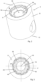
- the piston 2 according to the embodiment shown in fig. 1a is shown in closer detail in figs. 2-3 .
- the piston 2 has the basic shape of a right circular cylinder with an upper end 11 and a lower end 12, between which a central axis C and a peripheral envelope surface 13 extend.
- the upper end 11 comprises an annular top surface 14 defining an upper plane.
- the piston bowl 3 is recessed with respect to the upper plane defined by the top surface 14.
- the piston bowl 3 comprises a central bottom portion 15 sloping downward from a central point located on the central axis C.
- the central bottom portion 15 is cone shaped with a rounded top 16, which top 16 is recessed with respect to the upper plane.
- the piston bowl 3 further comprises a side wall surrounding the central bottom portion 15.
- the side wall has a curved, slightly S-shaped upper side wall portion 17 that slopes downward and radially inward from the annular top surface 14. It further has a concave lower side wall portion 18 defining a lowest level of the piston bowl.
- the lower side wall portion 18 extends from the central bottom portion 15 toward the upper side wall portion 17. Between the lower side wall portion 18 and the upper side wall portion 17, a knee 19 projecting toward the central axis C is formed.
- the piston bowl 3 has a two dimensional profile comprising two profile portions 20a, 20b located on opposite sides of the central axis C.
- each of the profile portions 20a, 20b is displaced in and out with respect to the central axis C in dependence on an oscillating function.
- the oscillating function is in the form of a sinusoid, so that a distance from the central axis C to the side wall varies with an angular displacement ⁇ of the vertical plane around the central axis C.
- other periodic or non-periodic oscillating functions are possible to use instead of a sinusoid. It is also possible to use e.g. a combination of sinusoids or other trigonometric functions.
- this function can be used to describe the distance from the central axis C to any point on the side wall as a function of angular displacement, i.e. not only to the knee 19 but also to the lower side wall portion 18 and to the upper side wall portion 17.
- the amplitude a can be determined in a global optimization of the combustion system under the range of operating conditions of the internal combustion engine. For example, a volume of the piston bowl 3, a fuel injection pattern, a level of swirl and a compression ratio can be taken into account.
- each point of the profile portion 20a, 20b discussed above will follow a path described by the equation (1).
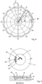
- the side wall thereby has a wavy surface. This can also be described as ripples being formed in the side wall. In the embodiment shown in figs. 1-3 , a total of ten ripples are formed. If the path shown in fig. 4 is used to design a piston bowl, a total of twelve ripples will be formed in the side wall.
- the central bottom portion may be formed with a wavy surface, although in the shown embodiment the central bottom portion 15 is cone shaped without ripples formed in the surface.
- the fuel injector 6 is configured for injecting fuel into the cylinder 1 as a fuel jet 25, so that the fuel is mixed with air compressed in the cylinder 1 to form a fuel/air mixture.
- the fuel/air mixture is after an ignition delay ignited by compression heat generated in the cylinder 1.
- the ignited part of the fuel jet 25 forms a flame.
- the fuel can be injected with different injection pressures, from low to very high pressures.
- the fuel injector 6 includes a plurality of small injection orifices (not shown), formed in the lower end of a nozzle assembly of the fuel injector 6 for permitting the high pressure fuel to flow from a nozzle cavity of the fuel injector 6 into the combustion chamber 5 with high pressure to induce thorough mixing of the fuel with the hot compressed air within the combustion chamber 5.
- the fuel injector 6 may be any type of fuel injector capable of injecting high pressure fuel through a plurality of injector orifices into the combustion chamber 5.
- the fuel injector need not necessarily be positioned on the central axis C.
- the injection orifices of the fuel injector 6 are arranged so that the fuel jets 25 are injected toward target positions on, above or below the knee 19.
- the target positions are preferably also located on, below or above portions 23 of the knee 19 which are closest to the central axis C.
- the piston 2 is moving along the central axis C as the fuel jets 25 are injected, and therefore the exact target positions in the axial direction will vary.
- the target positions aimed for in the axial direction also depends on e.g. load and injection timing. As the ignited fuel jets 25, i.e. the flames, strikes the target positions, the flames are split on the knee 19 into an upper flow portion and a lower flow portion, but also on the portion 23 of the knee 19 so that mixing of fuel/air in the non-axial direction is enhanced.
- Fig. 5 schematically shows the flow of fuel in the combustion chamber 5 after injection of fuel in an upper end view (top) and in a cross sectional view along the line D-D (bottom).
- a large scale swirl has been created during the intake stroke of the piston 2, as depicted by the arrow 21.
- the fuel jet 25 is split in the axial direction.
- the rippled side wall interrupts the circulation of the swirl flow close to the side wall, creating instability in the local flow motion close to the side wall. Gradients are thereby created in the tangential velocity of the swirl flow, leading to the creation of local vortices as depicted by the arrows 22.
Landscapes
- Engineering & Computer Science (AREA)
- Chemical & Material Sciences (AREA)
- Combustion & Propulsion (AREA)
- Mechanical Engineering (AREA)
- General Engineering & Computer Science (AREA)
- Dispersion Chemistry (AREA)
- Combustion Methods Of Internal-Combustion Engines (AREA)
- Pistons, Piston Rings, And Cylinders (AREA)
Description
- The present invention relates to a piston for an internal combustion engine according to the preamble of
claim 1 and to an internal combustion engine comprising at least one cylinder with such a piston. It also relates to a motor vehicle comprising an internal combustion engine. - While the piston is primarily discussed with respect to diesel engines, it is to be understood that the piston may be used in any kind of internal combustion engine using direct injection of fuel, i.e. injection of fuel into a combustion chamber where the fuel is ignited to provide piston movement.
- Internal combustion engines such as diesel engines, also known as compression-ignition engines, and Otto engines, or sparkignition engines, are commonly used in different types of motor vehicles, such as trucks and buses, cars, vessels, etc. Internal combustion engines are also used in many industrial applications.
- Internal combustion engines, hereinafter also referred to as engines, may be driven by a plurality of different types of fuel, such as diesel, petrol, ethanol, gaseous fuel, and biofuel. The engines have a number of cylinders in which a reciprocating piston is provided. In an upper end of the piston, a piston bowl is provided.
- Together with an upper part of the cylinder and a cylinder head, the piston bowl forms a combustion chamber in which fuel is injected and combusted. The piston bowl is designed to contribute to mixing of air and fuel and to create a flow pattern influencing combustion and emission formation within the combustion chamber.
- In a diesel engine, the fuel is normally injected as a fuel spray, or fuel jet, with a very high pressure subsequent to an intake stroke and a compression stroke of the piston. The fuel is ignited by the compression heat and combusted almost immediately following injection. Air and fuel must therefore be mixed in a very short time, and it is desirable to ensure that the mixing is efficient and that the fuel becomes well-distributed within the combustion chamber so as to achieve a complete combustion. In this type of engine, the burning rate of the fuel is controlled by the entrainment of the surrounding in-cylinder air into the fuel spray. Faster burning rates lead to higher efficiencies of the thermodynamic cycle, which in turn can translate into more fuel efficient engines. Piston bowl designs which can increase fuel-air mixing rates are therefore of particular interest.
- Increasingly stringent emission regulations, for diesel engines relating primarily to soot and nitrogen oxide (NOx) emissions, make it necessary to aim at further improving the emission control of internal combustion engines. However, more efficient emission control often require more complex and energy demanding aftertreatment and combustion systems, which particularly in the case of the aftertreatment system may contribute to an increased fuel consumption. For example, a swirl motion may be created to form turbulence in the combustion chamber and efficiently mix fuel with air. The swirl motion is a large scale whirling motion around the axis of the cylinder, which is typically created during the intake stroke of the piston by e.g. helical intake ports. Together with a high fuel injection pressure, the swirl motion may improve the combustion conditions and thereby reduces emission levels.
-
SE533053 - However, in order to further improve the combustion conditions and reduce emission levels, there is a need to further enhance the conditions for mixing of fuel and air within the combustion chamber.
-
US 2011/0253094 A1 discloses a piston comprising a bowl having an inner surface including at least one surface feature that forms at least one edge portion as a target for the fuel spray. The surface features are described to reduce soot and improve fuel-air mixing. -
US 2005/252483 A1 discloses a piston comprising a piston recess provided with a plurality of radial cavities extending from the recess radially into the piston head for receiving fuel injected into the combustion chamber.US 2009/050101 A1 andUS5215052A disclose other pistons. - It is a primary objective of the present invention to provide a piston for an internal combustion engine which has a piston bowl configured to improve the efficiency of combustion and to reduce emission levels. A second objective is to provide an internal combustion engine in which emission levels can be reduced and the fuel efficiency can be increased.
- At least the first objective is achieved by means of the initially defined piston for an internal combustion engine, characterised in that if the vertical plane in which the section is taken is revolved around the central axis, each one of the profile portions is displaced in and out with respect to the central axis in dependence on an oscillating function, so that a distance from the central axis to the side wall varies with an angular displacement of the vertical plane. In other words, ripples are formed in the side wall of the piston bowl. The two profile portions, which may be mutually symmetric, thus have the same appearance regardless of where around the central axis the longitudinal section is taken, but are displaced with respect to the central axis depending on the angular displacement of the vertical plane. All parts of the side wall, i.e. the upper side wall portion, the knee and the concave lower side wall portion, are displaced with respect to the central axis as the vertical plane is revolved around the central axis. The displacement of the profile portions with respect to the central axis may be along a line perpendicular to the central axis, i.e. a radius of the piston bowl. The oscillating function is a smooth trigonometric function.
- The piston according to the invention has the advantage that the level of turbulence close to the side wall of the piston bowl is locally increased. A large scale swirl motion created on an intake stroke of the piston is broken down into smaller turbulent eddies and local recirculation vortices. As fuel is injected into the piston bowl in the form of fuel jets, the flow pattern created close to the side wall is therefore expected to enhance the turbulent fuel-air mixing at leading ends of the fuel jets, thus producing a more rapid burning rate which positively affects the efficiency of the thermodynamic cycle. Accordingly, a reduction of the engine fuel consumption can be expected.
- The piston bowl design may further contribute to increasing the turbulent intensity during the last part of the combustion cycle, and thereby enhances late-cycle oxidation of fuel and intermediate combustion products. This is beneficial for increasing the energy efficiency of the internal combustion engine in which the piston is provided.
- The piston according to the invention can be used in existing internal combustion engines without heavy modifications. It is relatively easy to implement in existing engine designs and requires no additional hardware to function as desired.
- The oscillating function is a periodic function. The piston bowl can thereby easily be adapted for a fuel injector with a nozzle designed to inject fuel into the combustion chamber with a symmetric fuel injection pattern, i.e. with orifices for injecting fuel being evenly distributed around the nozzle. By varying the periodicity of the function, the piston can be tailored for a particular number of fuel jets. The periodic function is a smooth function, so that a side wall without sharp corners is generated.
- The oscillating function is a smooth trigonometric function. The trigonometric function may e.g. be in the form of a sinusoid or a combination of sinusoids, but also other trigonometric functions are possible. A smooth trigonometric function, such as a sinusoid, generates a piston bowl without sharp corners, which may otherwise trap fuel and result in incomplete combustion.
- According to one embodiment, the oscillating function is such that at least eight ripples are formed in the side wall, preferably at least ten ripples. A sufficient number of recesses in the side wall for creating local turbulence are thereby provided. The number of ripples may be independent of the fuel injection pattern, but it may also be correlated. The number of ripples formed in the side wall can be optimized taking for example the fuel injection pattern, the level of swirl and the compression ratio into account.
- According to another aspect of the present invention, at least the second objective is achieved by means of an internal combustion engine comprising at least one cylinder with the proposed piston. Advantages of such an internal combustion engine appear from the above description of the piston. Of course, the internal combustion engine may comprise a plurality of cylinders having the proposed piston. The internal combustion engine may be adapted for use within a motor vehicle or within a stationary machine such as a pump or an electrical generator.
- According to one embodiment, the internal combustion engine further comprises a fuel injector configured to inject and direct fuel toward a number of target positions located on the side wall. The fuel injector may e.g. have nozzle with a number of orifices for fuel injection. Preferably, the fuel injector may be positioned on the central axis.
- According to one embodiment, the target positions are angularly located on, below or above portions of the knee which are closest to the central axis. In this way, fuel is directed toward portions of the side wall that protrude toward the central axis. As the fuel jets, or rather ignited fuel jets in the form of flames, impact on the target positions, the fuel jets/flames are split both axially by means of the knee, but also laterally. Instead of obtaining a two dimensional splitting of fuel, a three dimensional splitting of fuel is achieved.
- According to one embodiment, the number of target positions is a multiple of a number of ripples formed in the side wall. By correlating the number of target positions with the number of ripples formed in the side wall, for example such that the number of ripples and the number of target positions coincide, the mixing of fuel and air may in some applications be optimized. However, it is not necessary that the number of ripples coincide with the number of target positions. A correlation between the number of ripples and the number of target positions can be optimized taking for example the fuel injection pattern, the level of swirl and the compression ratio into account.
- The invention also relates to a motor vehicle comprising the proposed internal combustion engine. The motor vehicle may be a heavy motor vehicle such as a truck or a bus, but it may also be e.g. a passenger car or another motor vehicle.
- Further advantages as well as advantageous features of the present invention will appear from the following detailed description.
- Embodiments of the invention will in the following be described with reference to the appended drawings, in which:
- Fig. 1a
- schematically shows an axial section of a cylinder of an internal combustion engine including a piston according to an embodiment,
- Fig. 1b
- schematically shows a motor vehicle according to an embodiment,
- Fig. 2
- is a perspective view of the piston in
fig. 1a , - Fig. 3
- is an upper end view of the piston in
fig. 2 , - Fig. 4
- shows a curve describing the shape of the piston bowl according to an embodiment, and
- Fig. 5
- schematically shows flow of fuel in a piston bowl according to an embodiment.
-
Fig. 1a shows acylinder 1 of an internal combustion engine in the form of a diesel engine according to an embodiment of the invention. In thecylinder 1, apiston 2 configured to reciprocate within the cylinder along a common central axis C is provided. Apiston bowl 3 is formed in thepiston 2, which together with internal walls of thecylinder 1 and an internal surface of a cylinder head 4 creates acombustion chamber 5. A fuel injector 6 is positioned on the central axis C above thepiston bowl 3. An intake port 7 is provided in the cylinder head 4 for supply of air into thecombustion chamber 5 via an intake valve 8. Furthermore, an exhaust port 9 is provided in the cylinder head 4 for evacuation of exhaust gases via anexhaust valve 10. - A
motor vehicle 100 according to an embodiment of the invention is schematically shown infig. 1b . Themotor vehicle 100 comprises aninternal combustion engine 101 forming part of apowertrain 102 which drives drivingwheels cylinders 1, of which only one is schematically shown, is provided in the combustion engine. Eachcylinder 1 is provided with a piston bowl according to an embodiment of the invention. Themotor vehicle 100 further comprises anexhaust treatment system 105. - The
piston 2 according to the embodiment shown infig. 1a is shown in closer detail infigs. 2-3 . Thepiston 2 has the basic shape of a right circular cylinder with anupper end 11 and alower end 12, between which a central axis C and aperipheral envelope surface 13 extend. Theupper end 11 comprises an annulartop surface 14 defining an upper plane. Thepiston bowl 3 is recessed with respect to the upper plane defined by thetop surface 14. - The
piston bowl 3 comprises acentral bottom portion 15 sloping downward from a central point located on the central axis C. Thecentral bottom portion 15 is cone shaped with a rounded top 16, which top 16 is recessed with respect to the upper plane. Thepiston bowl 3 further comprises a side wall surrounding thecentral bottom portion 15. The side wall has a curved, slightly S-shaped upperside wall portion 17 that slopes downward and radially inward from the annulartop surface 14. It further has a concave lowerside wall portion 18 defining a lowest level of the piston bowl. The lowerside wall portion 18 extends from thecentral bottom portion 15 toward the upperside wall portion 17. Between the lowerside wall portion 18 and the upperside wall portion 17, aknee 19 projecting toward the central axis C is formed. As seen in a section taken in a vertical plane including the central axis C, such as shown infig. 1a , thepiston bowl 3 has a two dimensional profile comprising twoprofile portions - If the vertical plane in which the section is taken is revolved around the central axis C of the
piston 2, each of theprofile portions Fig. 4 shows a path that describes the appearance of a medial transverse section of theknee 19 of thepiston bowl 3, wherein a radial distance ρ (solid line) from the central axis C to theknee 19 varies between r ± 0.5a, wherein r (dashed line) is an average radial distance r from the central axis C to theknee 19 and a is the amplitude of the variation. In the shown embodiment, the radial distance ρ can, as a function of the angular displacement θ, be described as:
knee 19 but also to the lowerside wall portion 18 and to the upperside wall portion 17. The amplitude a can be determined in a global optimization of the combustion system under the range of operating conditions of the internal combustion engine. For example, a volume of thepiston bowl 3, a fuel injection pattern, a level of swirl and a compression ratio can be taken into account. - If one of the
profile portions profile portion figs. 1-3 , a total of ten ripples are formed. If the path shown infig. 4 is used to design a piston bowl, a total of twelve ripples will be formed in the side wall. Also the central bottom portion may be formed with a wavy surface, although in the shown embodiment thecentral bottom portion 15 is cone shaped without ripples formed in the surface. - The fuel injector 6 is configured for injecting fuel into the
cylinder 1 as afuel jet 25, so that the fuel is mixed with air compressed in thecylinder 1 to form a fuel/air mixture. The fuel/air mixture is after an ignition delay ignited by compression heat generated in thecylinder 1. The ignited part of thefuel jet 25 forms a flame. The fuel can be injected with different injection pressures, from low to very high pressures. The fuel injector 6 includes a plurality of small injection orifices (not shown), formed in the lower end of a nozzle assembly of the fuel injector 6 for permitting the high pressure fuel to flow from a nozzle cavity of the fuel injector 6 into thecombustion chamber 5 with high pressure to induce thorough mixing of the fuel with the hot compressed air within thecombustion chamber 5. It should be understood that the fuel injector 6 may be any type of fuel injector capable of injecting high pressure fuel through a plurality of injector orifices into thecombustion chamber 5. Also, the fuel injector need not necessarily be positioned on the central axis C. - The injection orifices of the fuel injector 6 are arranged so that the
fuel jets 25 are injected toward target positions on, above or below theknee 19. The target positions are preferably also located on, below or aboveportions 23 of theknee 19 which are closest to the central axis C. It should be noted that thepiston 2 is moving along the central axis C as thefuel jets 25 are injected, and therefore the exact target positions in the axial direction will vary. The target positions aimed for in the axial direction also depends on e.g. load and injection timing. As the ignitedfuel jets 25, i.e. the flames, strikes the target positions, the flames are split on theknee 19 into an upper flow portion and a lower flow portion, but also on theportion 23 of theknee 19 so that mixing of fuel/air in the non-axial direction is enhanced. -
Fig. 5 schematically shows the flow of fuel in thecombustion chamber 5 after injection of fuel in an upper end view (top) and in a cross sectional view along the line D-D (bottom). In the embodiment shown infig. 5 , a large scale swirl has been created during the intake stroke of thepiston 2, as depicted by thearrow 21. Upon injection of fuel in the form of afuel jet 25 directed toward a target position, in this case located on aportion 24 of theknee 19 located furthest from the central axis C, thefuel jet 25 is split in the axial direction. At the same time, the rippled side wall interrupts the circulation of the swirl flow close to the side wall, creating instability in the local flow motion close to the side wall. Gradients are thereby created in the tangential velocity of the swirl flow, leading to the creation of local vortices as depicted by thearrows 22. - The invention is of course not in any way restricted to the embodiments described above. On the contrary, many possibilities to modifications thereof will be apparent to a person with ordinary skill in the art without departing from the basic idea of the invention such as defined in the appended claims.
Claims (8)
- A piston (2) for an internal combustion engine (101), wherein the piston (2) has an upper end (11) and a lower end (12) between which a central axis (C) and a peripheral envelope surface (13) extend, wherein the upper end (11) comprises an annular top surface (14) defining a plane and a piston bowl (3) configured to form part of a combustion chamber (5), wherein the piston bowl (3) is recessed with respect to the annular top surface (14) and comprises a central bottom portion (15) sloping downward from a central point located on the central axis (C) and a side wall surrounding the central bottom portion (15), the side wall comprising:- an upper side wall portion (17) sloping downward and radially inward from the annular top surface (14),- a concave lower side wall portion (18) defining a lowest level of the piston bowl (3), extending from the central bottom portion (15) toward the upper side wall portion (17),- a knee (19) formed in a transition between the upper side wall portion (17) and the concave lower side wall portion (18), projecting toward the central axis (C),wherein, as seen in a section taken in a vertical plane including the central axis (C), the piston bowl (3) has a two dimensional profile comprising two profile portions (20a, 20b) located on opposite sides of the central axis (C),characterised inthat, if the vertical plane in which the section is taken is revolved around the central axis (C), each one of the profile portions (20a, 20b) is displaced in and out with respect to the central axis (C) in dependence on an oscillating function, so that all parts of the side wall are displaced with respect to the central axis in dependence on the oscillating function, so that a distance from the central axis (C) to the side wall varies with an angular displacement (θ) of the vertical plane around the central axis (C), andwherein the oscillating function is a smooth trigonometric function.
- The piston according to any one of the preceding claims, wherein the oscillating function is such that at least eight ripples are formed in the side wall, preferably at least ten ripples.
- An internal combustion engine (101) comprising at least one cylinder (1) with a piston (2) according to any one of the preceding claims.
- The internal combustion engine according to claim 3, further comprising a fuel injector (6) configured to inject and direct fuel toward a number of target positions located on the side wall.
- The internal combustion engine according to claim 4, wherein the target positions are angularly located on, below or above portions (23) of the knee (19) which are closest to the central axis (C).
- The internal combustion engine according to claim 4 or 5, wherein the number of target positions is a multiple of a number of ripples formed in the side wall.
- A motor vehicle (100) comprising an internal combustion engine (101) according to claim 5 or 6.
- The motor vehicle according to claim 7, wherein the motor vehicle is a heavy motor vehicle such as a truck or a bus.
Applications Claiming Priority (2)
| Application Number | Priority Date | Filing Date | Title |
|---|---|---|---|
| SE1750412A SE540868E (en) | 2017-04-04 | 2017-04-04 | A piston for an internal combustion engine |
| PCT/SE2018/050328 WO2018186786A1 (en) | 2017-04-04 | 2018-03-27 | A piston for an internal combustion engine |
Publications (3)
| Publication Number | Publication Date |
|---|---|
| EP3607196A1 EP3607196A1 (en) | 2020-02-12 |
| EP3607196A4 EP3607196A4 (en) | 2020-10-28 |
| EP3607196B1 true EP3607196B1 (en) | 2024-11-20 |
Family
ID=63713461
Family Applications (1)
| Application Number | Title | Priority Date | Filing Date |
|---|---|---|---|
| EP18781265.6A Active EP3607196B1 (en) | 2017-04-04 | 2018-03-27 | A piston for an internal combustion engine |
Country Status (3)
| Country | Link |
|---|---|
| EP (1) | EP3607196B1 (en) |
| SE (1) | SE540868E (en) |
| WO (1) | WO2018186786A1 (en) |
Citations (1)
| Publication number | Priority date | Publication date | Assignee | Title |
|---|---|---|---|---|
| US5215052A (en) * | 1991-08-21 | 1993-06-01 | Mercedes-Benz Ag | Internal-combustion engine with predominantly swirl-free air inflow into a shallow combustion space |
Family Cites Families (13)
| Publication number | Priority date | Publication date | Assignee | Title |
|---|---|---|---|---|
| US4635597A (en) * | 1985-01-16 | 1987-01-13 | Yanmar Diesel Engine Co., Ltd. | Structure of a main combustion chamber of a diesel engine of a direct injection type |
| JP4002823B2 (en) * | 2002-12-11 | 2007-11-07 | ヤンマー株式会社 | Engine combustion chamber |
| DE10261185A1 (en) * | 2002-12-20 | 2004-07-15 | Daimlerchrysler Ag | Direct injection Otto internal combustion engine |
| JP4906055B2 (en) * | 2006-02-08 | 2012-03-28 | 日野自動車株式会社 | Combustion chamber structure of direct injection diesel engine |
| DE102006020642B4 (en) * | 2006-05-04 | 2019-05-23 | Daimler Ag | Method for operating an internal combustion engine and internal combustion engine for such a method |
| US8020530B2 (en) * | 2007-06-15 | 2011-09-20 | Federal-Mogul Corporation | Piston and internal combustion engine therewith and method of constructing the piston |
| BRPI0722151B1 (en) * | 2007-10-30 | 2019-10-29 | Volvo Lastvagnar Ab | device for reducing emissions in a vehicle internal combustion engine |
| SE533053C2 (en) | 2008-06-13 | 2010-06-15 | Scania Cv Ab | Piston of an internal combustion engine |
| US8459229B2 (en) * | 2010-04-20 | 2013-06-11 | Southwest Research Institute | Piston bowl with spray jet targets |
| JP6100916B2 (en) * | 2012-12-18 | 2017-03-22 | ボルボ トラック コーポレイション | Piston for internal combustion engine cylinder |
| FR3012522B1 (en) * | 2013-10-25 | 2018-08-24 | IFP Energies Nouvelles | COMBUSTION ENGINE WITH DIRECT INJECTION OF COMPRESSION IGNITION FUEL AND FUEL INJECTION METHOD FOR SUCH ENGINE. |
| DE102015205349A1 (en) * | 2015-03-24 | 2016-09-29 | Mtu Friedrichshafen Gmbh | Internal combustion engine and piston for an internal combustion engine |
| US20170145951A1 (en) * | 2015-11-19 | 2017-05-25 | Caterpillar Inc. | Textured Piston |
-
2017
- 2017-04-04 SE SE1750412A patent/SE540868E/en unknown
-
2018
- 2018-03-27 EP EP18781265.6A patent/EP3607196B1/en active Active
- 2018-03-27 WO PCT/SE2018/050328 patent/WO2018186786A1/en not_active Ceased
Patent Citations (1)
| Publication number | Priority date | Publication date | Assignee | Title |
|---|---|---|---|---|
| US5215052A (en) * | 1991-08-21 | 1993-06-01 | Mercedes-Benz Ag | Internal-combustion engine with predominantly swirl-free air inflow into a shallow combustion space |
Also Published As
| Publication number | Publication date |
|---|---|
| EP3607196A1 (en) | 2020-02-12 |
| WO2018186786A1 (en) | 2018-10-11 |
| EP3607196A4 (en) | 2020-10-28 |
| SE540868C2 (en) | 2018-12-11 |
| SE1750412A1 (en) | 2018-10-05 |
| SE540868E (en) | 2026-03-24 |
Similar Documents
| Publication | Publication Date | Title |
|---|---|---|
| EP3596320B1 (en) | A piston for an internal combustion engine | |
| CN104981595B (en) | Piston for the cylinder of explosive motor | |
| US8967129B2 (en) | Ducted combustion chamber for direct injection engines and method | |
| EP2529094B1 (en) | Direct injection diesel engines | |
| CN101970828B (en) | Device for reducing emissions from internal combustion engines of vehicles | |
| US8459229B2 (en) | Piston bowl with spray jet targets | |
| US6966294B2 (en) | Internal combustion engine producing low emissions | |
| EP2187017B1 (en) | Diesel engine, piston for diesel engine and method of manufacturing a diesel engine | |
| JP6869244B2 (en) | Internal combustion engine piston crown | |
| JP5741594B2 (en) | Piston arranged to reciprocate in the combustion engine cylinder | |
| US10731544B2 (en) | Internal combustion engine and method for its operation | |
| US9995203B2 (en) | Piston design for flow re-direction | |
| US10774782B2 (en) | Piston design for flow re-direction | |
| US7918206B2 (en) | Device for reducing soot emissions in a vehicle combustion engine | |
| EP3607196B1 (en) | A piston for an internal combustion engine | |
| US10876464B2 (en) | Piston design for flow re-direction | |
| US20200116103A1 (en) | Piston design for splitting jets into streams | |
| US20250382911A1 (en) | Internal combustion engine with hydrogen direct injection | |
| WO2021066708A1 (en) | Compression ignition engine with improved fuel distribution and vehicle comprising the engine |
Legal Events
| Date | Code | Title | Description |
|---|---|---|---|
| STAA | Information on the status of an ep patent application or granted ep patent |
Free format text: STATUS: THE INTERNATIONAL PUBLICATION HAS BEEN MADE |
|
| PUAI | Public reference made under article 153(3) epc to a published international application that has entered the european phase |
Free format text: ORIGINAL CODE: 0009012 |
|
| STAA | Information on the status of an ep patent application or granted ep patent |
Free format text: STATUS: REQUEST FOR EXAMINATION WAS MADE |
|
| 17P | Request for examination filed |
Effective date: 20191104 |
|
| AK | Designated contracting states |
Kind code of ref document: A1 Designated state(s): AL AT BE BG CH CY CZ DE DK EE ES FI FR GB GR HR HU IE IS IT LI LT LU LV MC MK MT NL NO PL PT RO RS SE SI SK SM TR |
|
| AX | Request for extension of the european patent |
Extension state: BA ME |
|
| DAV | Request for validation of the european patent (deleted) | ||
| DAX | Request for extension of the european patent (deleted) | ||
| A4 | Supplementary search report drawn up and despatched |
Effective date: 20200928 |
|
| RIC1 | Information provided on ipc code assigned before grant |
Ipc: F02F 3/24 20060101ALI20200922BHEP Ipc: F02F 3/28 20060101ALI20200922BHEP Ipc: F02F 3/26 20060101AFI20200922BHEP Ipc: F02B 23/06 20060101ALI20200922BHEP |
|
| RAP3 | Party data changed (applicant data changed or rights of an application transferred) |
Owner name: SCANIA CV AB |
|
| P01 | Opt-out of the competence of the unified patent court (upc) registered |
Effective date: 20230518 |
|
| STAA | Information on the status of an ep patent application or granted ep patent |
Free format text: STATUS: EXAMINATION IS IN PROGRESS |
|
| TPAC | Observations filed by third parties |
Free format text: ORIGINAL CODE: EPIDOSNTIPA |
|
| 17Q | First examination report despatched |
Effective date: 20230630 |
|
| GRAP | Despatch of communication of intention to grant a patent |
Free format text: ORIGINAL CODE: EPIDOSNIGR1 |
|
| STAA | Information on the status of an ep patent application or granted ep patent |
Free format text: STATUS: GRANT OF PATENT IS INTENDED |
|
| INTG | Intention to grant announced |
Effective date: 20240619 |
|
| GRAS | Grant fee paid |
Free format text: ORIGINAL CODE: EPIDOSNIGR3 |
|
| GRAA | (expected) grant |
Free format text: ORIGINAL CODE: 0009210 |
|
| STAA | Information on the status of an ep patent application or granted ep patent |
Free format text: STATUS: THE PATENT HAS BEEN GRANTED |
|
| AK | Designated contracting states |
Kind code of ref document: B1 Designated state(s): AL AT BE BG CH CY CZ DE DK EE ES FI FR GB GR HR HU IE IS IT LI LT LU LV MC MK MT NL NO PL PT RO RS SE SI SK SM TR |
|
| REG | Reference to a national code |
Ref country code: GB Ref legal event code: FG4D |
|
| REG | Reference to a national code |
Ref country code: CH Ref legal event code: EP |
|
| REG | Reference to a national code |
Ref country code: DE Ref legal event code: R096 Ref document number: 602018076749 Country of ref document: DE |
|
| REG | Reference to a national code |
Ref country code: IE Ref legal event code: FG4D |
|
| REG | Reference to a national code |
Ref country code: SE Ref legal event code: TRGR |
|
| REG | Reference to a national code |
Ref country code: LT Ref legal event code: MG9D |
|
| REG | Reference to a national code |
Ref country code: NL Ref legal event code: MP Effective date: 20241120 |
|
| PG25 | Lapsed in a contracting state [announced via postgrant information from national office to epo] |
Ref country code: HR Free format text: LAPSE BECAUSE OF FAILURE TO SUBMIT A TRANSLATION OF THE DESCRIPTION OR TO PAY THE FEE WITHIN THE PRESCRIBED TIME-LIMIT Effective date: 20241120 Ref country code: IS Free format text: LAPSE BECAUSE OF FAILURE TO SUBMIT A TRANSLATION OF THE DESCRIPTION OR TO PAY THE FEE WITHIN THE PRESCRIBED TIME-LIMIT Effective date: 20250320 Ref country code: PT Free format text: LAPSE BECAUSE OF FAILURE TO SUBMIT A TRANSLATION OF THE DESCRIPTION OR TO PAY THE FEE WITHIN THE PRESCRIBED TIME-LIMIT Effective date: 20250320 |
|
| PG25 | Lapsed in a contracting state [announced via postgrant information from national office to epo] |
Ref country code: NL Free format text: LAPSE BECAUSE OF FAILURE TO SUBMIT A TRANSLATION OF THE DESCRIPTION OR TO PAY THE FEE WITHIN THE PRESCRIBED TIME-LIMIT Effective date: 20241120 Ref country code: FI Free format text: LAPSE BECAUSE OF FAILURE TO SUBMIT A TRANSLATION OF THE DESCRIPTION OR TO PAY THE FEE WITHIN THE PRESCRIBED TIME-LIMIT Effective date: 20241120 |
|
| REG | Reference to a national code |
Ref country code: AT Ref legal event code: MK05 Ref document number: 1743781 Country of ref document: AT Kind code of ref document: T Effective date: 20241120 |
|
| PG25 | Lapsed in a contracting state [announced via postgrant information from national office to epo] |
Ref country code: BG Free format text: LAPSE BECAUSE OF FAILURE TO SUBMIT A TRANSLATION OF THE DESCRIPTION OR TO PAY THE FEE WITHIN THE PRESCRIBED TIME-LIMIT Effective date: 20241120 |
|
| PG25 | Lapsed in a contracting state [announced via postgrant information from national office to epo] |
Ref country code: ES Free format text: LAPSE BECAUSE OF FAILURE TO SUBMIT A TRANSLATION OF THE DESCRIPTION OR TO PAY THE FEE WITHIN THE PRESCRIBED TIME-LIMIT Effective date: 20241120 |
|
| PG25 | Lapsed in a contracting state [announced via postgrant information from national office to epo] |
Ref country code: NO Free format text: LAPSE BECAUSE OF FAILURE TO SUBMIT A TRANSLATION OF THE DESCRIPTION OR TO PAY THE FEE WITHIN THE PRESCRIBED TIME-LIMIT Effective date: 20250220 |
|
| PG25 | Lapsed in a contracting state [announced via postgrant information from national office to epo] |
Ref country code: GR Free format text: LAPSE BECAUSE OF FAILURE TO SUBMIT A TRANSLATION OF THE DESCRIPTION OR TO PAY THE FEE WITHIN THE PRESCRIBED TIME-LIMIT Effective date: 20250221 Ref country code: LV Free format text: LAPSE BECAUSE OF FAILURE TO SUBMIT A TRANSLATION OF THE DESCRIPTION OR TO PAY THE FEE WITHIN THE PRESCRIBED TIME-LIMIT Effective date: 20241120 Ref country code: AT Free format text: LAPSE BECAUSE OF FAILURE TO SUBMIT A TRANSLATION OF THE DESCRIPTION OR TO PAY THE FEE WITHIN THE PRESCRIBED TIME-LIMIT Effective date: 20241120 |
|
| PG25 | Lapsed in a contracting state [announced via postgrant information from national office to epo] |
Ref country code: PL Free format text: LAPSE BECAUSE OF FAILURE TO SUBMIT A TRANSLATION OF THE DESCRIPTION OR TO PAY THE FEE WITHIN THE PRESCRIBED TIME-LIMIT Effective date: 20241120 |
|
| PG25 | Lapsed in a contracting state [announced via postgrant information from national office to epo] |
Ref country code: RS Free format text: LAPSE BECAUSE OF FAILURE TO SUBMIT A TRANSLATION OF THE DESCRIPTION OR TO PAY THE FEE WITHIN THE PRESCRIBED TIME-LIMIT Effective date: 20250220 |
|
| PG25 | Lapsed in a contracting state [announced via postgrant information from national office to epo] |
Ref country code: SM Free format text: LAPSE BECAUSE OF FAILURE TO SUBMIT A TRANSLATION OF THE DESCRIPTION OR TO PAY THE FEE WITHIN THE PRESCRIBED TIME-LIMIT Effective date: 20241120 |
|
| PG25 | Lapsed in a contracting state [announced via postgrant information from national office to epo] |
Ref country code: DK Free format text: LAPSE BECAUSE OF FAILURE TO SUBMIT A TRANSLATION OF THE DESCRIPTION OR TO PAY THE FEE WITHIN THE PRESCRIBED TIME-LIMIT Effective date: 20241120 |
|
| PG25 | Lapsed in a contracting state [announced via postgrant information from national office to epo] |
Ref country code: EE Free format text: LAPSE BECAUSE OF FAILURE TO SUBMIT A TRANSLATION OF THE DESCRIPTION OR TO PAY THE FEE WITHIN THE PRESCRIBED TIME-LIMIT Effective date: 20241120 |
|
| PG25 | Lapsed in a contracting state [announced via postgrant information from national office to epo] |
Ref country code: RO Free format text: LAPSE BECAUSE OF FAILURE TO SUBMIT A TRANSLATION OF THE DESCRIPTION OR TO PAY THE FEE WITHIN THE PRESCRIBED TIME-LIMIT Effective date: 20241120 |
|
| PG25 | Lapsed in a contracting state [announced via postgrant information from national office to epo] |
Ref country code: SK Free format text: LAPSE BECAUSE OF FAILURE TO SUBMIT A TRANSLATION OF THE DESCRIPTION OR TO PAY THE FEE WITHIN THE PRESCRIBED TIME-LIMIT Effective date: 20241120 |
|
| PG25 | Lapsed in a contracting state [announced via postgrant information from national office to epo] |
Ref country code: CZ Free format text: LAPSE BECAUSE OF FAILURE TO SUBMIT A TRANSLATION OF THE DESCRIPTION OR TO PAY THE FEE WITHIN THE PRESCRIBED TIME-LIMIT Effective date: 20241120 |
|
| PG25 | Lapsed in a contracting state [announced via postgrant information from national office to epo] |
Ref country code: IT Free format text: LAPSE BECAUSE OF FAILURE TO SUBMIT A TRANSLATION OF THE DESCRIPTION OR TO PAY THE FEE WITHIN THE PRESCRIBED TIME-LIMIT Effective date: 20241120 |
|
| REG | Reference to a national code |
Ref country code: DE Ref legal event code: R097 Ref document number: 602018076749 Country of ref document: DE |
|
| PLBE | No opposition filed within time limit |
Free format text: ORIGINAL CODE: 0009261 |
|
| STAA | Information on the status of an ep patent application or granted ep patent |
Free format text: STATUS: NO OPPOSITION FILED WITHIN TIME LIMIT |
|
| PG25 | Lapsed in a contracting state [announced via postgrant information from national office to epo] |
Ref country code: MC Free format text: LAPSE BECAUSE OF FAILURE TO SUBMIT A TRANSLATION OF THE DESCRIPTION OR TO PAY THE FEE WITHIN THE PRESCRIBED TIME-LIMIT Effective date: 20241120 |
|
| 26N | No opposition filed |
Effective date: 20250821 |
|
| REG | Reference to a national code |
Ref country code: CH Ref legal event code: H13 Free format text: ST27 STATUS EVENT CODE: U-0-0-H10-H13 (AS PROVIDED BY THE NATIONAL OFFICE) Effective date: 20251023 |
|
| PG25 | Lapsed in a contracting state [announced via postgrant information from national office to epo] |
Ref country code: LU Free format text: LAPSE BECAUSE OF NON-PAYMENT OF DUE FEES Effective date: 20250327 |
|
| PG25 | Lapsed in a contracting state [announced via postgrant information from national office to epo] |
Ref country code: CH Free format text: LAPSE BECAUSE OF NON-PAYMENT OF DUE FEES Effective date: 20250331 |
|
| PG25 | Lapsed in a contracting state [announced via postgrant information from national office to epo] |
Ref country code: IE Free format text: LAPSE BECAUSE OF NON-PAYMENT OF DUE FEES Effective date: 20250327 |
|
| PGFP | Annual fee paid to national office [announced via postgrant information from national office to epo] |
Ref country code: SE Payment date: 20260211 Year of fee payment: 9 |
|
| PGFP | Annual fee paid to national office [announced via postgrant information from national office to epo] |
Ref country code: GB Payment date: 20260209 Year of fee payment: 9 |
|
| PGFP | Annual fee paid to national office [announced via postgrant information from national office to epo] |
Ref country code: DE Payment date: 20260204 Year of fee payment: 9 |
|
| PGFP | Annual fee paid to national office [announced via postgrant information from national office to epo] |
Ref country code: BE Payment date: 20260216 Year of fee payment: 9 |
|
| PGFP | Annual fee paid to national office [announced via postgrant information from national office to epo] |
Ref country code: FR Payment date: 20260209 Year of fee payment: 9 |