EP3607158B1 - Locking system for door, and extendible wire conduit therefore - Google Patents
Locking system for door, and extendible wire conduit therefore Download PDFInfo
- Publication number
- EP3607158B1 EP3607158B1 EP18781351.4A EP18781351A EP3607158B1 EP 3607158 B1 EP3607158 B1 EP 3607158B1 EP 18781351 A EP18781351 A EP 18781351A EP 3607158 B1 EP3607158 B1 EP 3607158B1
- Authority
- EP
- European Patent Office
- Prior art keywords
- locking system
- door
- wire conduit
- lock
- inner housing
- Prior art date
- Legal status (The legal status is an assumption and is not a legal conclusion. Google has not performed a legal analysis and makes no representation as to the accuracy of the status listed.)
- Active
Links
Images





Classifications
-
- E—FIXED CONSTRUCTIONS
- E05—LOCKS; KEYS; WINDOW OR DOOR FITTINGS; SAFES
- E05B—LOCKS; ACCESSORIES THEREFOR; HANDCUFFS
- E05B65/00—Locks or fastenings for special use
- E05B65/0032—Locks or fastenings for special use for hotel rooms
-
- E—FIXED CONSTRUCTIONS
- E05—LOCKS; KEYS; WINDOW OR DOOR FITTINGS; SAFES
- E05B—LOCKS; ACCESSORIES THEREFOR; HANDCUFFS
- E05B9/00—Lock casings or latch-mechanism casings ; Fastening locks or fasteners or parts thereof to the wing
- E05B9/08—Fastening locks or fasteners or parts thereof, e.g. the casings of latch-bolt locks or cylinder locks to the wing
-
- E—FIXED CONSTRUCTIONS
- E05—LOCKS; KEYS; WINDOW OR DOOR FITTINGS; SAFES
- E05B—LOCKS; ACCESSORIES THEREFOR; HANDCUFFS
- E05B15/00—Other details of locks; Parts for engagement by bolts of fastening devices
- E05B15/02—Striking-plates; Keepers; Bolt staples; Escutcheons
-
- E—FIXED CONSTRUCTIONS
- E05—LOCKS; KEYS; WINDOW OR DOOR FITTINGS; SAFES
- E05B—LOCKS; ACCESSORIES THEREFOR; HANDCUFFS
- E05B47/00—Operating or controlling locks or other fastening devices by electric or magnetic means
- E05B47/0001—Operating or controlling locks or other fastening devices by electric or magnetic means with electric actuators; Constructional features thereof
-
- E—FIXED CONSTRUCTIONS
- E05—LOCKS; KEYS; WINDOW OR DOOR FITTINGS; SAFES
- E05B—LOCKS; ACCESSORIES THEREFOR; HANDCUFFS
- E05B63/00—Locks or fastenings with special structural characteristics
- E05B63/0056—Locks with adjustable or exchangeable lock parts
- E05B63/006—Locks with adjustable or exchangeable lock parts for different door thicknesses
-
- G—PHYSICS
- G07—CHECKING-DEVICES
- G07C—TIME OR ATTENDANCE REGISTERS; REGISTERING OR INDICATING THE WORKING OF MACHINES; GENERATING RANDOM NUMBERS; VOTING OR LOTTERY APPARATUS; ARRANGEMENTS, SYSTEMS OR APPARATUS FOR CHECKING NOT PROVIDED FOR ELSEWHERE
- G07C9/00—Individual registration on entry or exit
- G07C9/00174—Electronically operated locks; Circuits therefor; Nonmechanical keys therefor, e.g. passive or active electrical keys or other data carriers without mechanical keys
- G07C9/00571—Electronically operated locks; Circuits therefor; Nonmechanical keys therefor, e.g. passive or active electrical keys or other data carriers without mechanical keys operated by interacting with a central unit
-
- E—FIXED CONSTRUCTIONS
- E05—LOCKS; KEYS; WINDOW OR DOOR FITTINGS; SAFES
- E05B—LOCKS; ACCESSORIES THEREFOR; HANDCUFFS
- E05B15/00—Other details of locks; Parts for engagement by bolts of fastening devices
- E05B15/0046—Ratchet mechanisms
-
- E—FIXED CONSTRUCTIONS
- E05—LOCKS; KEYS; WINDOW OR DOOR FITTINGS; SAFES
- E05B—LOCKS; ACCESSORIES THEREFOR; HANDCUFFS
- E05B47/00—Operating or controlling locks or other fastening devices by electric or magnetic means
- E05B2047/0048—Circuits, feeding, monitoring
- E05B2047/0057—Feeding
- E05B2047/0058—Feeding by batteries
-
- E—FIXED CONSTRUCTIONS
- E05—LOCKS; KEYS; WINDOW OR DOOR FITTINGS; SAFES
- E05B—LOCKS; ACCESSORIES THEREFOR; HANDCUFFS
- E05B47/00—Operating or controlling locks or other fastening devices by electric or magnetic means
- E05B2047/0048—Circuits, feeding, monitoring
- E05B2047/0067—Monitoring
-
- E—FIXED CONSTRUCTIONS
- E05—LOCKS; KEYS; WINDOW OR DOOR FITTINGS; SAFES
- E05B—LOCKS; ACCESSORIES THEREFOR; HANDCUFFS
- E05B47/00—Operating or controlling locks or other fastening devices by electric or magnetic means
- E05B2047/0048—Circuits, feeding, monitoring
- E05B2047/0071—Connecting lockparts by electronic communication means only, e.g. bus systems, time multiplexing
-
- E—FIXED CONSTRUCTIONS
- E05—LOCKS; KEYS; WINDOW OR DOOR FITTINGS; SAFES
- E05B—LOCKS; ACCESSORIES THEREFOR; HANDCUFFS
- E05B47/00—Operating or controlling locks or other fastening devices by electric or magnetic means
- E05B2047/0094—Mechanical aspects of remotely controlled locks
- E05B2047/0095—Mechanical aspects of locks controlled by telephone signals, e.g. by mobile phones
-
- E—FIXED CONSTRUCTIONS
- E05—LOCKS; KEYS; WINDOW OR DOOR FITTINGS; SAFES
- E05B—LOCKS; ACCESSORIES THEREFOR; HANDCUFFS
- E05B47/00—Operating or controlling locks or other fastening devices by electric or magnetic means
- E05B47/06—Controlling mechanically-operated bolts by electro-magnetically-operated detents
- E05B47/0676—Controlling mechanically-operated bolts by electro-magnetically-operated detents by disconnecting the handle
-
- E—FIXED CONSTRUCTIONS
- E05—LOCKS; KEYS; WINDOW OR DOOR FITTINGS; SAFES
- E05B—LOCKS; ACCESSORIES THEREFOR; HANDCUFFS
- E05B63/00—Locks or fastenings with special structural characteristics
- E05B63/0056—Locks with adjustable or exchangeable lock parts
Definitions
- the improvements generally relate to the field of electrical locking systems for doors of buildings.
- Such locking systems are widely used in hotels, motels and other rental dwellings, but are also used in many other applications.
- Such locking systems typically have a controller, often provided in the form of a relatively simple computer, which has an input interface to receive an input serving as the "key".
- the controller 20 performs an authentication function determining whether or not the input from the electronic key 22 is authorized to operate the lock, and controls a lock actuator 24 to open the lock 26 upon authorization.
- the key 22 is electronically coded as part of an electronic key (e.g.
- the locking system has a reader interface 32 to read it in a contact or a contactless manner (e.g. swipe interface, card readers, reader antennas, "tap" readers, Bluetooth TM ).
- the key data can be a memorized number which is entered via a keypad provided as part of the locking system, for instance.
- such locks are also self-powered and thus also include a battery.
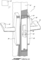
- FIGs 1A and 1B A specific example of such a locking system 10 assembled to a door 12 is shown in Figs 1A and 1B .
- This specific locking system is of the 'mortise type' and has the lock provided in a pocket 14 which is loaded into a corresponding cavity - the mortise - which is defined in the door 12.
- the various electrical (including electronic) components can include some components housed in the outer housing 16, and other components housed in the inner housing 18.
- the outside lever 33 can be activated to retract the latch 34, allowing subsequent opening of the door.
- the inside lever 35 is not lockable, though it is common for an additional bolt 36 to be provided which can be manually and mechanically activated from the inside via a bolt actuator 38 (typically a simple knob).
- a bolt actuator 38 typically a simple knob.
- Other examples such as EP 0978611 A2 , describes a locking system for doors, US 2009/275229 A1 is related to a device for the electrical connection of electrical or electronic components, and US 2005/179267 A1 describes a lock control system with a lock-down feature.
- an electrical conduit can be provided between the outside housing and the inner housing, to provide a passage for electrical wires therebetween.
- Cost and quality vs. price ratio control are standing concerns in the design of locking systems, in addition to other concerns such as style, durability, security, etc. Doors come in various thicknesses. It was found advantageous to provide locking system models which could adapt to various thicknesses of doors. Indeed, providing different locking system models for different sizes of doors could significant affect overall costs given the additional complexity of managing a more complex inventory and the increased likelihood of errors and problems at installation. It was found advantageous to provide an electrical conduit which was extendible and thus adaptable to various thicknesses of doors.
- a locking system for a door in accordance with claim 1.
- a controller can be a computer or some other form of electronic or electrical device which is adapted to perform a controlling function.
- the expression 'computer' is used in a broad sense to generally refer to the combination of some form of one or more processing units and some form of memory system accessible by the processing unit(s).
- a computer can be a network node, a personal computer, a smart phone, an appliance computer, etc.
- Figs 2A and 2B show a first example of a telescoping wire conduit 40.
- the telescoping wire 40 conduit includes a base member 42 and an extension member 44.
- the base member 42 has a proximal end 46 secured to the outer housing 48 and a distal end 50 protruding from the outer housing 48, opposite the proximal end 46, for extending into the door and guiding the wires 52 across the thickness of the door.
- the extension member 44 is telescopingly mounted to the base member 42.
- the telescoping wire conduit 40 is made integral to the outer housing 48 in this embodiment, more specifically due to the fact that the proximal end 46 of the base member 42 is secured to the outer housing 48, the telescoping wire conduit 40 can be instead secured to the inner housing 18 and extend away from the inner housing 18, across the door 12, in alternate embodiments.
- the relative telescoping movement of the extension member 44 relative the base member 42 is guided and is lockable, via a keyway 54 and key 56 engagement.
- the base member 46 has a keyway 54.
- the keyway 54 forms an inverted L, with a longitudinal segment 58 extending longitudinally between the proximate end 46 and the distal end 50, and a circumferential segment 60 at the distal end 50.
- a mating key 56 is provided in the form of a radial protuberance formed in the extension member 44. Accordingly, the locking system can be shipped with the telescoping wire conduit 40 being positioned in a retracted state.
- the extension member 44 can be extended and its key 56 can be pulled along the longitudinal segment 54 of the keyway 58, and then locked in the extended state shown in Fig. 2A by rotating the extension member 44 to move the key in the circumferential segment 60.
- the locked wire conduit can be engaged across the door, and protrude into the inside housing, across a back plate thereof (the cover of the inside housing will typically have been removed for installation), at which stage the wires 52, or more specifically the connectors 62 thereof, will be accessible to the assembly technician on the other face of the door. The assembly technician can then connect the wires 52 to connect any of the electrical components which need a wired connection across the door.
- the technician can rotate the extension member 44 to move the key 56 back into the longitudinal segment 58, and can push the extension member 44 in a manner to move the key 56 along the longitudinal segment 58, and thus retract the extension member 44 back into the door, to the extent desired (e.g. such as shown in Fig. 2B ).
- the cover can then be replaced onto the internal housing to complete the installation.
- the base member 42 has a keyway 58 and the extension member 44 has a key 56, but it will be understood that in alternate embodiments, the extension member 44 can have a keyway 58 and the base member 42 have a key 56.
- FIG. 3A and 3B Another example of a telescoping wire conduit 140 is shown in Figs. 3A and 3B .
- the two telescoping members 142, 144 are engaged to one another via teeth 170 and pawl 172 engagement forming a ratchet 174, in a manner that the telescoping members 142, 144 can be extended linearly across the ratchet 174, and that the ratchet 174 can prevent a contrary retraction (compression) movement.
- the telescoping wire conduit is secured to and extends from a outer housing 148.
- the telescoping wire conduit 140 can be shipped in its retracted state, such as shown in Fig. 3A .
- the technician can determine the thickness of the door, and extend the extension member 144 relative to the base member 142 selectively, to a level of extension which corresponds to the predetermined thickness of the door.
- the technician can introduce the wire conduit 140 across the door 177, as it can be seen to extend across the mortise 178 for the purpose of illustration in Fig. 3C , and protrude slightly across a corresponding aperture 180 in the back plate 182 of the inner housing 184, such as shown in Fig. 3D , for wire connection.
- the pawl and teeth engagement can be designed in a manner that if the technician erroneously extends the extension member 144 too much, he can disengage the pawl from the teeth, return the extension member 144 to its retracted state, and retry.
- the lock pocket is absent from the mortise for the purpose of illustration.
- the lock pocket will have been engaged within the mortise 178 prior to engaging the wire conduit 140 across the door, and the wire conduit 140 will extend across a corresponding aperture formed within the lock pocket.
- the connectors 186, at the end of the wires are made integral to the extension member 144.
- the wire conduit 140 can extend above or below the mortise, or a telescoping wire conduit can be used for other lock types than mortise locks, such as latch locks, for instance.
- Fig. 4 shows another example of a telescoping member 240 having a ratchet-type engagement.
- ratchets 290, 292 which are diametrically opposite one another and are both longitudinally oriented, and the extension member 244 is external to the base member 242 rather than internal thereto as in the previous examples.
- the telescoping wire conduit 40, 140, 240 can be used to adjust its length for different door thicknesses, for example approximately 3.49 cm to 6.35 cm (1-3/8" to 2-1/2"). 1, 2, 3, 4, or more cables can extend thereacross, depending on the specific type of locking system and the functions provided therewith.
- the outer housing can include a RFID antenna (for a key card), a Zigbee antenna (for automated control of electrical equipment of the room), a bluetooth antenna (allowing to open the lock with a smart phone), a main PCB housing a primary controller unit of the locking system and an activation clutch.
- the inner housing can include the following components, all connected to the outer housing through the telescoping wire conduit : a lever switch to detect movement of the handle; a privacy switch to detect rotation of the turn knob; batteries (e.g.
- the lock can, too, have an electrical component having a wire connected via the wire conduit.
- a mortise lock can have a door ajar switch wiredly connected to the outer housing via the wire conduit.
- some or all of the components presented above can be omitted or be located at a different location (e.g. in the inner housing rather than in the outer housing).
- both the base member and the extension member are generally cylindrical, but other telescoping shapes can be used in other embodiments.
- the telescoping wire conduit is made integral to the outer housing, but it will be understood that in alternate embodiments, it can be made integral to the internal housing instead, and extend towards to the outer housing for connection of the wires thereto.
- the detailed examples provided above are well adapted to be embodied with mortise-type locks, it will be understood that the telescoping wire conduit can be adapted to other types of lock systems. For instance, Fig.
- FIG. 5 shows a lock having an electronic deadbolt 336, and a telescoping wire conduit can be used to pass wires associated with the electronic deadbolt 336 across the door.
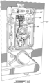
- Fig. 6A and 6B show a lock system in which a reader is provided in a housing on the outer face of the door, but is separate from the lever ( Fig. 6A shows the outer face whereas Fig. 6B shows the inner face).
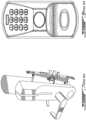
- Fig. 7 shows an embodiment where the lock system has a "swipe"-type card reader.
- Fig. 8 shows an embodiment where the lock system has a keypad-type interface for receiving a numerical key.
- telescoping wire conduit can be used to connect various types of electrical components which require wired connections across the door, and that in various forms of locks, the exact nature and location (inner housing or outer housing) of such electrical components can vary.
- Fig. 9 is provided to show various alternatives of locks which can be used between an inner housing and an outer housing, more specifically : a dead bolt lock, an american mortise lock, a latch lock, and a European mortise lock.
- Other types of locks can be used in alternate embodiments.
- a telescoping wire conduit can be used in association with any one of the examples presented above and illustrated, as found suitable by persons skilled in the art. The scope is indicated by the appended claims.
Landscapes
- Engineering & Computer Science (AREA)
- Mechanical Engineering (AREA)
- Physics & Mathematics (AREA)
- General Physics & Mathematics (AREA)
- Structural Engineering (AREA)
- Lock And Its Accessories (AREA)
- Insertion, Bundling And Securing Of Wires For Electric Apparatuses (AREA)
- Installation Of Indoor Wiring (AREA)
Description
- The improvements generally relate to the field of electrical locking systems for doors of buildings.
- Various forms of electrically-powered locking systems for doors exist. Such locking systems are widely used in hotels, motels and other rental dwellings, but are also used in many other applications. Such locking systems typically have a controller, often provided in the form of a relatively simple computer, which has an input interface to receive an input serving as the "key". The
controller 20 performs an authentication function determining whether or not the input from theelectronic key 22 is authorized to operate the lock, and controls alock actuator 24 to open thelock 26 upon authorization. In most cases, thekey 22 is electronically coded as part of an electronic key (e.g. data 30 on a swipe card, chip card, RFID card, or data stored on a computer memory such as a smartphone memory) and the locking system has areader interface 32 to read it in a contact or a contactless manner (e.g. swipe interface, card readers, reader antennas, "tap" readers, Bluetooth™). Alternately, the key data can be a memorized number which is entered via a keypad provided as part of the locking system, for instance. Typically, such locks are also self-powered and thus also include a battery. - A specific example of such a
locking system 10 assembled to adoor 12 is shown inFigs 1A and1B . This specific locking system is of the 'mortise type' and has the lock provided in apocket 14 which is loaded into a corresponding cavity - the mortise - which is defined in thedoor 12. The various electrical (including electronic) components can include some components housed in theouter housing 16, and other components housed in theinner housing 18. - When the
lock 26 is open following positive authentication, theoutside lever 33 can be activated to retract thelatch 34, allowing subsequent opening of the door. Typically, in this type oflocking system 10, theinside lever 35 is not lockable, though it is common for anadditional bolt 36 to be provided which can be manually and mechanically activated from the inside via a bolt actuator 38 (typically a simple knob).
Other examples, such asEP 0978611 A2 , describes a locking system for doors,US 2009/275229 A1 is related to a device for the electrical connection of electrical or electronic components, andUS 2005/179267 A1 describes a lock control system with a lock-down feature. - Known systems were satisfactory to a certain degree. However, there always remains room for improvement.
- In electrical locking systems, an electrical conduit can be provided between the outside housing and the inner housing, to provide a passage for electrical wires therebetween. Cost and quality vs. price ratio control are standing concerns in the design of locking systems, in addition to other concerns such as style, durability, security, etc. Doors come in various thicknesses. It was found advantageous to provide locking system models which could adapt to various thicknesses of doors. Indeed, providing different locking system models for different sizes of doors could significant affect overall costs given the additional complexity of managing a more complex inventory and the increased likelihood of errors and problems at installation. It was found advantageous to provide an electrical conduit which was extendible and thus adaptable to various thicknesses of doors.
- In accordance with one aspect of the invention, there is provided a locking system for a door in accordance with claim 1.
- It will be understood that the expressions 'computer' and 'controller', as used herein, are not to be interpreted in a limiting manner. A controller can be a computer or some other form of electronic or electrical device which is adapted to perform a controlling function. The expression 'computer' is used in a broad sense to generally refer to the combination of some form of one or more processing units and some form of memory system accessible by the processing unit(s). A computer can be a network node, a personal computer, a smart phone, an appliance computer, etc.
- It will be understood that the various functions of the computer, or more specifically of the processing unit, can be performed by hardware, by software, or by a combination of both. For example, hardware can include logic gates included as part of a silicon chip of the processor. Software can be in the form of data such as computer-readable instructions stored in a memory system.
- In accordance with another aspect of the invention, there is provided a method of installing a locking system in accordance with
claim 10. - Many further features and combinations thereof concerning the present improvements will appear to those skilled in the art following a reading of the instant disclosure. The scope of the invention is defined by the appended claims.
- In the figures,
-
Fig. 1A is an oblique view of an example of a locking system mounted to a door, in accordance with the prior art; -
Fig. 1B is a block diagram showing the communication flow between an electronic key and a locking system; -
Fig. 2A and 2B are oblique views showing a first example of a telescoping wire conduit in an extended, and a retracted configurations, respectively; -
Fig. 3A and 3B are oblique views showing a second example of a telescoping wire conduit in a retracted, and an extended configurations, respectively; -
Fig. 3C and3D are oblique views showing the telescoping wire conduit mounted to a door; -
Fig. 4 is an oblique view of a third example of a telescoping wire conduit; -
Fig. 5 is a front elevation view of a second example of a locking system in accordance with the prior art; -
Fig. 6A and 6B are outside and internal views, respectively, of a third example locking system in accordance with the prior art; -
Fig. 7 is an oblique view of a fourth example of a locking system, in accordance with the prior art; -
Fig. 8 is a front elevation view of a fifth example of a locking system, in accordance with the prior art; and -
Fig. 9 is a schematic view showing variants. -
Figs 2A and 2B show a first example of atelescoping wire conduit 40. In these figures, thetelescoping wire 40 conduit includes abase member 42 and anextension member 44. Thebase member 42 has aproximal end 46 secured to theouter housing 48 and adistal end 50 protruding from theouter housing 48, opposite theproximal end 46, for extending into the door and guiding thewires 52 across the thickness of the door. Theextension member 44 is telescopingly mounted to thebase member 42. It will be understood that although thetelescoping wire conduit 40 is made integral to theouter housing 48 in this embodiment, more specifically due to the fact that theproximal end 46 of thebase member 42 is secured to theouter housing 48, thetelescoping wire conduit 40 can be instead secured to theinner housing 18 and extend away from theinner housing 18, across thedoor 12, in alternate embodiments. - Moreover, in this embodiment, the relative telescoping movement of the
extension member 44 relative thebase member 42 is guided and is lockable, via akeyway 54 and key 56 engagement. More specifically, thebase member 46 has akeyway 54. Thekeyway 54 forms an inverted L, with alongitudinal segment 58 extending longitudinally between theproximate end 46 and thedistal end 50, and acircumferential segment 60 at thedistal end 50. Amating key 56 is provided in the form of a radial protuberance formed in theextension member 44. Accordingly, the locking system can be shipped with thetelescoping wire conduit 40 being positioned in a retracted state. At the time of assembly, theextension member 44 can be extended and its key 56 can be pulled along thelongitudinal segment 54 of thekeyway 58, and then locked in the extended state shown inFig. 2A by rotating theextension member 44 to move the key in thecircumferential segment 60. At this stage, the locked wire conduit can be engaged across the door, and protrude into the inside housing, across a back plate thereof (the cover of the inside housing will typically have been removed for installation), at which stage thewires 52, or more specifically theconnectors 62 thereof, will be accessible to the assembly technician on the other face of the door. The assembly technician can then connect thewires 52 to connect any of the electrical components which need a wired connection across the door. Once the connection has been completed, the technician can rotate theextension member 44 to move the key 56 back into thelongitudinal segment 58, and can push theextension member 44 in a manner to move the key 56 along thelongitudinal segment 58, and thus retract theextension member 44 back into the door, to the extent desired (e.g. such as shown inFig. 2B ). The cover can then be replaced onto the internal housing to complete the installation. - Various modifications to this specific example are possible. For instance, in this embodiment, the
base member 42 has akeyway 58 and theextension member 44 has a key 56, but it will be understood that in alternate embodiments, theextension member 44 can have akeyway 58 and thebase member 42 have a key 56. - Another example of a
telescoping wire conduit 140 is shown inFigs. 3A and 3B . In this other example, the twotelescoping members teeth 170 andpawl 172 engagement forming aratchet 174, in a manner that thetelescoping members ratchet 174, and that theratchet 174 can prevent a contrary retraction (compression) movement. The telescoping wire conduit is secured to and extends from aouter housing 148. In this embodiment, thetelescoping wire conduit 140 can be shipped in its retracted state, such as shown inFig. 3A . At the time of assembly, the technician can determine the thickness of the door, and extend theextension member 144 relative to thebase member 142 selectively, to a level of extension which corresponds to the predetermined thickness of the door. At this stage, the technician can introduce thewire conduit 140 across thedoor 177, as it can be seen to extend across themortise 178 for the purpose of illustration inFig. 3C , and protrude slightly across a correspondingaperture 180 in theback plate 182 of the inner housing 184, such as shown inFig. 3D , for wire connection. The pawl and teeth engagement can be designed in a manner that if the technician erroneously extends theextension member 144 too much, he can disengage the pawl from the teeth, return theextension member 144 to its retracted state, and retry. InFig. 3C , the lock pocket is absent from the mortise for the purpose of illustration. During normal installation, in this embodiment, the lock pocket will have been engaged within themortise 178 prior to engaging thewire conduit 140 across the door, and thewire conduit 140 will extend across a corresponding aperture formed within the lock pocket. It will be noted that in this embodiment, theconnectors 186, at the end of the wires (not shown), are made integral to theextension member 144. In an alternate embodiment, thewire conduit 140 can extend above or below the mortise, or a telescoping wire conduit can be used for other lock types than mortise locks, such as latch locks, for instance. -
Fig. 4 shows another example of atelescoping member 240 having a ratchet-type engagement. In this example, there are twoopposite ratchets extension member 244 is external to thebase member 242 rather than internal thereto as in the previous examples. - The
telescoping wire conduit - Although it will be understood from the above that various alternate embodiments are possible, the details of a specific embodiment, for use as a possible example, will now be provided. More specifically, the telescoping wire conduit as shown in
Fig. 2A and 2B .
The outer housing can include a RFID antenna (for a key card), a Zigbee antenna (for automated control of electrical equipment of the room), a bluetooth antenna (allowing to open the lock with a smart phone), a main PCB housing a primary controller unit of the locking system and an activation clutch. The inner housing can include the following components, all connected to the outer housing through the telescoping wire conduit : a lever switch to detect movement of the handle; a privacy switch to detect rotation of the turn knob; batteries (e.g. 3 AA batteries); a bluetooth antenna and a Zigbee antenna. The lock can, too, have an electrical component having a wire connected via the wire conduit. For instance, a mortise lock can have a door ajar switch wiredly connected to the outer housing via the wire conduit. In alternate embodiments, some or all of the components presented above can be omitted or be located at a different location (e.g. in the inner housing rather than in the outer housing). - As can be understood, the examples described above and illustrated are intended to be exemplary only. For instance, in the illustrated embodiments, both the base member and the extension member are generally cylindrical, but other telescoping shapes can be used in other embodiments. Moreover, in the illustrated embodiments, the telescoping wire conduit is made integral to the outer housing, but it will be understood that in alternate embodiments, it can be made integral to the internal housing instead, and extend towards to the outer housing for connection of the wires thereto. Also, although the detailed examples provided above are well adapted to be embodied with mortise-type locks, it will be understood that the telescoping wire conduit can be adapted to other types of lock systems. For instance,
Fig. 5 shows a lock having anelectronic deadbolt 336, and a telescoping wire conduit can be used to pass wires associated with theelectronic deadbolt 336 across the door.Fig. 6A and 6B show a lock system in which a reader is provided in a housing on the outer face of the door, but is separate from the lever (Fig. 6A shows the outer face whereasFig. 6B shows the inner face).Fig. 7 shows an embodiment where the lock system has a "swipe"-type card reader.Fig. 8 shows an embodiment where the lock system has a keypad-type interface for receiving a numerical key. Moreover, it will be understood that the telescoping wire conduit can be used to connect various types of electrical components which require wired connections across the door, and that in various forms of locks, the exact nature and location (inner housing or outer housing) of such electrical components can vary. For the purpose of illustration,Fig. 9 is provided to show various alternatives of locks which can be used between an inner housing and an outer housing, more specifically : a dead bolt lock, an american mortise lock, a latch lock, and a european mortise lock. Other types of locks can be used in alternate embodiments. It will be understood that a telescoping wire conduit can be used in association with any one of the examples presented above and illustrated, as found suitable by persons skilled in the art. The scope is indicated by the appended claims.
Claims (13)
- A locking system for a door, the locking system comprising a lock, an outer housing (48, 148) adapted to be mounted to an outside face of the door, and an inner housing (18, 184) adapted to be mounted to an inside face of the door, a wire conduit (40, 140) mounted to one of the inner housing (18, 184) and the outer housing (48, 148) and adapted to extend across the door to the other one of the inner housing (18, 184) and the outer housing (48, 148), the wire conduit (40, 140) having two telescoping members (42, 44, 142, 144), and at least one wire (52) extending inside the wire conduit (40, 140) and adapted to be connected between a first locking system component housed in the outer housing (48, 148) and a second locking system component housed in the inner housing (18, 184), wherein the two telescoping members (42, 44, 142, 144) include a base member (42, 142) and an extension member (44, 144), the base member (42, 142) having a proximal end (46) secured to said one of the inner housing (18, 184) and the outer housing (48, 148) and a distal end (50) adapted to extend into the door.
- The locking system of claim 1 having a keyway (54) including a longitudinal segment (58) extending longitudinally between the proximal end (46) and a distal end (50) of the base member (42), and a circumferential segment (60) at the distal end (50), and the extension member (44) has a radially-extending protuberance forming a key (56) being engaged in the keyway (54), wherein the two telescoping members (42, 44) can be locked into an extended position for installation, in which the key (56) is engaged with the circumferential segment (60), and unlocked from the extended position by moving the key (56) into the longitudinal segment (58), for retracting the extension member (44) once the wire connections have been made.
- The locking system of claim 1 wherein the two telescoping members (142, 144) are engaged to one another via a teeth (170) and pawl (172) engagement forming a ratchet (174), in a manner that the telescoping members (142, 144) can be extended linearly across the ratchet (174), and that the ratchet (174) can prevent a contrary retraction movement.
- The locking system of claim 1 wherein the locking system includes a plurality of electrical locking system components including the first locking system component and the second locking system component, the electrical locking system components individually being housed in one of the outer housing (48, 148) and the inner housing (18, 184); wherein the plurality of electrical locking system components include at least: a battery, a reader for receiving an input from an electronic key, a lock actuator operable to activate the lock, a controller being adapted for receiving the input from the reader, determining whether or not the corresponding electronic key is authorized to open the lock, and to control the lock actuator based on said determination.
- The locking system of claim 1 wherein the lock is a mortise lock forming part of a pack received in a mortise (178) formed into the door, and wherein said wire conduit (40, 140) extends across the pack.
- The locking system of claim 1 wherein the second locking system component is a battery which is housed in the inner housing (18, 184).
- The locking system of claim 1 wherein the wire conduit (40, 140) is mounted to the outer housing (48, 148) and extends towards the inner housing (18, 184) across the door.
- The locking system of claim 1 wherein the wire conduit (140) has a retraction prevention feature which can be used to prevent undesired retraction of the wire conduit (140) during installation.
- The locking system of claim 8 wherein the retraction prevention feature is a ratchet (174) engagement.
- A method of installing a locking system having an outer housing (48, 148), an inner housing (18, 184) and a lock, to a door, the method comprising extending a wire conduit (40, 140) having two telescoping members (42, 44, 142, 144), the wire conduit (42, 44, 142, 144) mounted to one of the outer housing (48, 148) and the inner housing (18, 184) of the locking system, mounting the outer housing (48, 148) to an outer face of the door and the inner housing (18, 184) to an inner face of the door, including engaging a free end of the extended wire conduit (40, 140) across the door, and connecting at least one wire (52) extending out from the free end of the wire conduit (40, 140).
- The method of claim 10 wherein said step of extending the wire conduit (140) includes selectively extending the wire conduit (140) to a length corresponding to a predetermined thickness of the door against a ratchet engagement (174) which prevents retraction.
- The method of claim 10 further comprising, subsequently to said extending, locking the wire conduit (40, 140) in the extended state.
- The method of claim 12 further comprising, subsequently to said connecting, unlocking and retracting the wire conduit (40, 140).
Applications Claiming Priority (2)
| Application Number | Priority Date | Filing Date | Title |
|---|---|---|---|
| US201762481732P | 2017-04-05 | 2017-04-05 | |
| PCT/CA2018/050354 WO2018184098A1 (en) | 2017-04-05 | 2018-03-23 | Locking system for door, and extendible wire conduit therefore |
Publications (3)
| Publication Number | Publication Date |
|---|---|
| EP3607158A1 EP3607158A1 (en) | 2020-02-12 |
| EP3607158A4 EP3607158A4 (en) | 2021-01-20 |
| EP3607158B1 true EP3607158B1 (en) | 2024-01-24 |
Family
ID=63712025
Family Applications (1)
| Application Number | Title | Priority Date | Filing Date |
|---|---|---|---|
| EP18781351.4A Active EP3607158B1 (en) | 2017-04-05 | 2018-03-23 | Locking system for door, and extendible wire conduit therefore |
Country Status (7)
| Country | Link |
|---|---|
| US (1) | US11255105B2 (en) |
| EP (1) | EP3607158B1 (en) |
| CN (1) | CN110446822B (en) |
| AU (1) | AU2018247582B2 (en) |
| CA (1) | CA3050154C (en) |
| MX (1) | MX2019010303A (en) |
| WO (1) | WO2018184098A1 (en) |
Families Citing this family (6)
| Publication number | Priority date | Publication date | Assignee | Title |
|---|---|---|---|---|
| CN109356452B (en) * | 2018-10-26 | 2024-05-10 | 广东樱花智能科技有限公司 | Panel clutch mechanism capable of reversing left and right |
| WO2021067543A1 (en) | 2019-10-02 | 2021-04-08 | Carrier Corporation | Battery carrier |
| WO2022099538A1 (en) * | 2020-11-12 | 2022-05-19 | 深圳市迈悍德实业有限公司 | Intelligent lock |
| DE102021212429A1 (en) * | 2021-11-04 | 2023-05-04 | Aug. Winkhaus Gmbh & Co. Kg | Drive unit for a locking device, in particular for a connecting rod lock of a door |
| WO2023114909A1 (en) | 2021-12-17 | 2023-06-22 | Spectrum Brands, Inc. | Electronic lock with mortise insert |
| US12430969B2 (en) * | 2024-02-29 | 2025-09-30 | Dormakaba Canada Inc. | Electronic lock |
Family Cites Families (32)
| Publication number | Priority date | Publication date | Assignee | Title |
|---|---|---|---|---|
| US995818A (en) | 1910-12-28 | 1911-06-20 | Russell & Erwin Mfg Co | Mortise-lock. |
| US2320177A (en) | 1941-03-14 | 1943-05-25 | Yale & Towne Mfg Co | Lock retainer |
| US2308322A (en) | 1941-10-31 | 1943-01-12 | Sargent & Co | Adjustable cylinder lock |
| US3358483A (en) | 1965-10-05 | 1967-12-19 | Hotel Security Systems Corp | Locks and mountings therefor |
| US3815390A (en) | 1972-10-30 | 1974-06-11 | Boston Lock & Safe Co Inc | Lock |
| US3899907A (en) | 1973-06-18 | 1975-08-19 | Herman Prahl | Cylinder lock assembly |
| US3934437A (en) | 1974-12-12 | 1976-01-27 | Alois Crepinsek | Door bolt lock |
| US4573334A (en) | 1983-01-24 | 1986-03-04 | Alois Crepinsek | Deadbolt lock adjustable for mounting in doors of various thicknesses |
| DE3641284A1 (en) | 1986-12-03 | 1988-06-16 | Hochtemperatur Reaktorbau Gmbh | CEILING REFLECTOR FOR A CORE REACTOR |
| DE19834692A1 (en) * | 1998-07-31 | 2000-02-03 | Wilke Heinrich Hewi Gmbh | Closure system for door with internal rotary knob attached to bolt actuating closure element has coupling unit that turns freely wrt. inner knob in free position, rotates with it in drive position |
| US6412317B1 (en) | 2000-10-30 | 2002-07-02 | Olympus Lock, Inc. | Integrated cabinet door and drawer handle and lock |
| JP4439720B2 (en) * | 2000-12-07 | 2010-03-24 | 株式会社ゴール | Radio wave key system |
| US6553799B2 (en) | 2001-02-23 | 2003-04-29 | Schlage Lock Company | Push button door locking mechanism |
| CN2656565Y (en) * | 2003-06-24 | 2004-11-17 | 昆明金安利信息技术有限公司 | Door lock structure capable of realizing interlocking linkage and emergency seal door function |
| US7501930B2 (en) | 2004-02-17 | 2009-03-10 | Harrow Products, Inc. | Lock control system with lock-down feature |
| JP4344723B2 (en) | 2005-10-28 | 2009-10-14 | 株式会社ベスト | Locking mechanism for hinged door |
| DE102006001267B3 (en) | 2006-01-10 | 2007-05-10 | Seccor High Security Gmbh | An extendable electronic cylinder lock has a modular build by which the cylinder may be adapted to accommodate different door thicknesses by adding extension pieces between the lock outer and inner parts |
| US20090027194A1 (en) * | 2006-02-24 | 2009-01-29 | Mcgrath Leigh Jason | Door locking/unlocking unit |
| AT503439B1 (en) | 2006-03-29 | 2007-10-15 | Evva Werke | DEVICE FOR THE ELECTRICAL CONNECTION OF ELECTRICAL OR ELECTRONIC COMPONENTS |
| DE602007012961D1 (en) * | 2006-06-30 | 2011-04-21 | Sumitomo Wiring Systems | Electrical connector |
| JP2008010340A (en) * | 2006-06-30 | 2008-01-17 | Sumitomo Wiring Syst Ltd | Connector |
| ES2435193T3 (en) * | 2007-02-08 | 2013-12-16 | Knock N'lock Ltd. | Solenoid operated electromechanical lock |
| CN102470780B (en) * | 2009-07-15 | 2015-04-08 | 约翰逊控股公司 | Mechatronic unlocking means |
| EP2354389B1 (en) | 2010-01-15 | 2012-09-19 | iLoq Oy | Electromechanical lock |
| US8690205B2 (en) | 2011-02-21 | 2014-04-08 | Yale Security Inc. | Door lockset |
| US9187929B2 (en) * | 2011-09-18 | 2015-11-17 | Hanchett Entry Systems, Inc. | Electronic cabinet/drawer lock system |
| KR200465835Y1 (en) * | 2011-11-21 | 2013-03-18 | 삼성에스엔에스 주식회사 | fireproof type digital doorlock |
| JP5681919B2 (en) | 2012-12-12 | 2015-03-11 | 株式会社ビートソニック | Vehicle door lock control device |
| CN203466883U (en) * | 2013-07-18 | 2014-03-05 | 北京新源恒通市政工程有限公司 | Portable handheld TV inspection equipment |
| CN203441201U (en) * | 2013-08-23 | 2014-02-19 | 阜阳万瑞斯电子锁业有限公司 | Lock with antenna window |
| CN203939328U (en) * | 2014-05-30 | 2014-11-12 | 长城汽车股份有限公司 | Bonnet louver bracing wire |
| CN206541989U (en) * | 2017-01-20 | 2017-10-03 | 南京物联传感技术有限公司 | Exempt from the flexible connector of wiring for smart lock |
-
2018
- 2018-03-23 US US16/473,305 patent/US11255105B2/en active Active
- 2018-03-23 EP EP18781351.4A patent/EP3607158B1/en active Active
- 2018-03-23 MX MX2019010303A patent/MX2019010303A/en unknown
- 2018-03-23 WO PCT/CA2018/050354 patent/WO2018184098A1/en not_active Ceased
- 2018-03-23 CN CN201880013780.XA patent/CN110446822B/en active Active
- 2018-03-23 AU AU2018247582A patent/AU2018247582B2/en active Active
- 2018-03-23 CA CA3050154A patent/CA3050154C/en active Active
Also Published As
| Publication number | Publication date |
|---|---|
| WO2018184098A1 (en) | 2018-10-11 |
| CA3050154C (en) | 2025-05-06 |
| US11255105B2 (en) | 2022-02-22 |
| AU2018247582A1 (en) | 2019-07-04 |
| AU2018247582B2 (en) | 2023-11-09 |
| CN110446822B (en) | 2020-12-11 |
| CN110446822A (en) | 2019-11-12 |
| EP3607158A4 (en) | 2021-01-20 |
| EP3607158A1 (en) | 2020-02-12 |
| CA3050154A1 (en) | 2018-10-11 |
| US20210285254A1 (en) | 2021-09-16 |
| MX2019010303A (en) | 2019-10-21 |
Similar Documents
| Publication | Publication Date | Title |
|---|---|---|
| CA3050154C (en) | Locking system for door, and extendible wire conduit therefore | |
| US12565795B2 (en) | Electromechanical lockset | |
| US12624574B2 (en) | Locking assembly with spring mechanism | |
| US8973417B2 (en) | Electronically-controlled removable core lock | |
| US10275965B2 (en) | Access control device commissioning | |
| CN111512010B (en) | Electronic lock | |
| US20220325557A1 (en) | Detection and correction of insufficient locking behavior of an electronic lockset | |
| EP3918161B1 (en) | Motorized trim | |
| CN116378510A (en) | Impact linkage and in-wall receiver | |
| US10352067B2 (en) | Key monitoring door lock, door lock key monitoring system, and method thereof | |
| AU2017383096B2 (en) | An electric strike | |
| WO2014209217A1 (en) | An electronic door lock transmission | |
| JP6615624B2 (en) | Lock system, door structure, and electronics | |
| US20180047231A1 (en) | History management system of electronic locking device | |
| KR102251387B1 (en) | Door lock authentication system for using room of public use space and Smart door lock thereof | |
| EP3132428B1 (en) | Electronic cam lock for cabinet doors, drawers and other applications | |
| WO2022254260A1 (en) | Electronic lock and implemantation process of said electronic lock | |
| CN120175162A (en) | A calibration method for smart lock and smart lock | |
| WO2022265607A1 (en) | Lock mechanism | |
| SE539126C2 (en) | Electronic door lock transmission | |
| EP2344713A1 (en) | Method for locking and unlocking a locking device |
Legal Events
| Date | Code | Title | Description |
|---|---|---|---|
| STAA | Information on the status of an ep patent application or granted ep patent |
Free format text: STATUS: THE INTERNATIONAL PUBLICATION HAS BEEN MADE |
|
| PUAI | Public reference made under article 153(3) epc to a published international application that has entered the european phase |
Free format text: ORIGINAL CODE: 0009012 |
|
| STAA | Information on the status of an ep patent application or granted ep patent |
Free format text: STATUS: REQUEST FOR EXAMINATION WAS MADE |
|
| 17P | Request for examination filed |
Effective date: 20190704 |
|
| AK | Designated contracting states |
Kind code of ref document: A1 Designated state(s): AL AT BE BG CH CY CZ DE DK EE ES FI FR GB GR HR HU IE IS IT LI LT LU LV MC MK MT NL NO PL PT RO RS SE SI SK SM TR |
|
| AX | Request for extension of the european patent |
Extension state: BA ME |
|
| DAV | Request for validation of the european patent (deleted) | ||
| A4 | Supplementary search report drawn up and despatched |
Effective date: 20201221 |
|
| RIC1 | Information provided on ipc code assigned before grant |
Ipc: E05B 47/06 20060101ALN20201215BHEP Ipc: E05B 9/08 20060101ALI20201215BHEP Ipc: E05B 47/00 20060101AFI20201215BHEP Ipc: E05B 15/02 20060101ALI20201215BHEP |
|
| RIC1 | Information provided on ipc code assigned before grant |
Ipc: E05B 15/00 20060101ALN20230810BHEP Ipc: E05B 47/06 20060101ALN20230810BHEP Ipc: E05B 63/00 20060101ALI20230810BHEP Ipc: E05B 65/00 20060101ALI20230810BHEP Ipc: E05B 9/08 20060101ALI20230810BHEP Ipc: E05B 15/02 20060101ALI20230810BHEP Ipc: E05B 47/00 20060101AFI20230810BHEP |
|
| RIC1 | Information provided on ipc code assigned before grant |
Ipc: E05B 15/00 20060101ALN20230925BHEP Ipc: E05B 47/06 20060101ALN20230925BHEP Ipc: E05B 63/00 20060101ALI20230925BHEP Ipc: E05B 65/00 20060101ALI20230925BHEP Ipc: E05B 9/08 20060101ALI20230925BHEP Ipc: E05B 15/02 20060101ALI20230925BHEP Ipc: E05B 47/00 20060101AFI20230925BHEP |
|
| GRAP | Despatch of communication of intention to grant a patent |
Free format text: ORIGINAL CODE: EPIDOSNIGR1 |
|
| STAA | Information on the status of an ep patent application or granted ep patent |
Free format text: STATUS: GRANT OF PATENT IS INTENDED |
|
| INTG | Intention to grant announced |
Effective date: 20231108 |
|
| GRAS | Grant fee paid |
Free format text: ORIGINAL CODE: EPIDOSNIGR3 |
|
| GRAA | (expected) grant |
Free format text: ORIGINAL CODE: 0009210 |
|
| STAA | Information on the status of an ep patent application or granted ep patent |
Free format text: STATUS: THE PATENT HAS BEEN GRANTED |
|
| AK | Designated contracting states |
Kind code of ref document: B1 Designated state(s): AL AT BE BG CH CY CZ DE DK EE ES FI FR GB GR HR HU IE IS IT LI LT LU LV MC MK MT NL NO PL PT RO RS SE SI SK SM TR |
|
| REG | Reference to a national code |
Ref country code: GB Ref legal event code: FG4D |
|
| REG | Reference to a national code |
Ref country code: CH Ref legal event code: EP |
|
| REG | Reference to a national code |
Ref country code: DE Ref legal event code: R096 Ref document number: 602018064523 Country of ref document: DE |
|
| REG | Reference to a national code |
Ref country code: IE Ref legal event code: FG4D |
|
| REG | Reference to a national code |
Ref country code: LT Ref legal event code: MG9D |
|
| REG | Reference to a national code |
Ref country code: NL Ref legal event code: MP Effective date: 20240124 |
|
| PG25 | Lapsed in a contracting state [announced via postgrant information from national office to epo] |
Ref country code: NL Free format text: LAPSE BECAUSE OF FAILURE TO SUBMIT A TRANSLATION OF THE DESCRIPTION OR TO PAY THE FEE WITHIN THE PRESCRIBED TIME-LIMIT Effective date: 20240124 |
|
| PG25 | Lapsed in a contracting state [announced via postgrant information from national office to epo] |
Ref country code: NL Free format text: LAPSE BECAUSE OF FAILURE TO SUBMIT A TRANSLATION OF THE DESCRIPTION OR TO PAY THE FEE WITHIN THE PRESCRIBED TIME-LIMIT Effective date: 20240124 |
|
| PG25 | Lapsed in a contracting state [announced via postgrant information from national office to epo] |
Ref country code: IS Free format text: LAPSE BECAUSE OF FAILURE TO SUBMIT A TRANSLATION OF THE DESCRIPTION OR TO PAY THE FEE WITHIN THE PRESCRIBED TIME-LIMIT Effective date: 20240524 |
|
| PG25 | Lapsed in a contracting state [announced via postgrant information from national office to epo] |
Ref country code: LT Free format text: LAPSE BECAUSE OF FAILURE TO SUBMIT A TRANSLATION OF THE DESCRIPTION OR TO PAY THE FEE WITHIN THE PRESCRIBED TIME-LIMIT Effective date: 20240124 |
|
| PG25 | Lapsed in a contracting state [announced via postgrant information from national office to epo] |
Ref country code: GR Free format text: LAPSE BECAUSE OF FAILURE TO SUBMIT A TRANSLATION OF THE DESCRIPTION OR TO PAY THE FEE WITHIN THE PRESCRIBED TIME-LIMIT Effective date: 20240425 |
|
| REG | Reference to a national code |
Ref country code: AT Ref legal event code: MK05 Ref document number: 1652325 Country of ref document: AT Kind code of ref document: T Effective date: 20240124 |
|
| PG25 | Lapsed in a contracting state [announced via postgrant information from national office to epo] |
Ref country code: RS Free format text: LAPSE BECAUSE OF FAILURE TO SUBMIT A TRANSLATION OF THE DESCRIPTION OR TO PAY THE FEE WITHIN THE PRESCRIBED TIME-LIMIT Effective date: 20240424 Ref country code: HR Free format text: LAPSE BECAUSE OF FAILURE TO SUBMIT A TRANSLATION OF THE DESCRIPTION OR TO PAY THE FEE WITHIN THE PRESCRIBED TIME-LIMIT Effective date: 20240124 |
|
| PG25 | Lapsed in a contracting state [announced via postgrant information from national office to epo] |
Ref country code: ES Free format text: LAPSE BECAUSE OF FAILURE TO SUBMIT A TRANSLATION OF THE DESCRIPTION OR TO PAY THE FEE WITHIN THE PRESCRIBED TIME-LIMIT Effective date: 20240124 |
|
| PG25 | Lapsed in a contracting state [announced via postgrant information from national office to epo] |
Ref country code: AT Free format text: LAPSE BECAUSE OF FAILURE TO SUBMIT A TRANSLATION OF THE DESCRIPTION OR TO PAY THE FEE WITHIN THE PRESCRIBED TIME-LIMIT Effective date: 20240124 |
|
| PG25 | Lapsed in a contracting state [announced via postgrant information from national office to epo] |
Ref country code: RS Free format text: LAPSE BECAUSE OF FAILURE TO SUBMIT A TRANSLATION OF THE DESCRIPTION OR TO PAY THE FEE WITHIN THE PRESCRIBED TIME-LIMIT Effective date: 20240424 Ref country code: NO Free format text: LAPSE BECAUSE OF FAILURE TO SUBMIT A TRANSLATION OF THE DESCRIPTION OR TO PAY THE FEE WITHIN THE PRESCRIBED TIME-LIMIT Effective date: 20240424 Ref country code: LT Free format text: LAPSE BECAUSE OF FAILURE TO SUBMIT A TRANSLATION OF THE DESCRIPTION OR TO PAY THE FEE WITHIN THE PRESCRIBED TIME-LIMIT Effective date: 20240124 Ref country code: IS Free format text: LAPSE BECAUSE OF FAILURE TO SUBMIT A TRANSLATION OF THE DESCRIPTION OR TO PAY THE FEE WITHIN THE PRESCRIBED TIME-LIMIT Effective date: 20240524 Ref country code: HR Free format text: LAPSE BECAUSE OF FAILURE TO SUBMIT A TRANSLATION OF THE DESCRIPTION OR TO PAY THE FEE WITHIN THE PRESCRIBED TIME-LIMIT Effective date: 20240124 Ref country code: GR Free format text: LAPSE BECAUSE OF FAILURE TO SUBMIT A TRANSLATION OF THE DESCRIPTION OR TO PAY THE FEE WITHIN THE PRESCRIBED TIME-LIMIT Effective date: 20240425 Ref country code: FI Free format text: LAPSE BECAUSE OF FAILURE TO SUBMIT A TRANSLATION OF THE DESCRIPTION OR TO PAY THE FEE WITHIN THE PRESCRIBED TIME-LIMIT Effective date: 20240124 Ref country code: ES Free format text: LAPSE BECAUSE OF FAILURE TO SUBMIT A TRANSLATION OF THE DESCRIPTION OR TO PAY THE FEE WITHIN THE PRESCRIBED TIME-LIMIT Effective date: 20240124 Ref country code: BG Free format text: LAPSE BECAUSE OF FAILURE TO SUBMIT A TRANSLATION OF THE DESCRIPTION OR TO PAY THE FEE WITHIN THE PRESCRIBED TIME-LIMIT Effective date: 20240124 Ref country code: AT Free format text: LAPSE BECAUSE OF FAILURE TO SUBMIT A TRANSLATION OF THE DESCRIPTION OR TO PAY THE FEE WITHIN THE PRESCRIBED TIME-LIMIT Effective date: 20240124 |
|
| PG25 | Lapsed in a contracting state [announced via postgrant information from national office to epo] |
Ref country code: PL Free format text: LAPSE BECAUSE OF FAILURE TO SUBMIT A TRANSLATION OF THE DESCRIPTION OR TO PAY THE FEE WITHIN THE PRESCRIBED TIME-LIMIT Effective date: 20240124 Ref country code: PT Free format text: LAPSE BECAUSE OF FAILURE TO SUBMIT A TRANSLATION OF THE DESCRIPTION OR TO PAY THE FEE WITHIN THE PRESCRIBED TIME-LIMIT Effective date: 20240524 |
|
| PG25 | Lapsed in a contracting state [announced via postgrant information from national office to epo] |
Ref country code: SE Free format text: LAPSE BECAUSE OF FAILURE TO SUBMIT A TRANSLATION OF THE DESCRIPTION OR TO PAY THE FEE WITHIN THE PRESCRIBED TIME-LIMIT Effective date: 20240124 Ref country code: PT Free format text: LAPSE BECAUSE OF FAILURE TO SUBMIT A TRANSLATION OF THE DESCRIPTION OR TO PAY THE FEE WITHIN THE PRESCRIBED TIME-LIMIT Effective date: 20240524 Ref country code: PL Free format text: LAPSE BECAUSE OF FAILURE TO SUBMIT A TRANSLATION OF THE DESCRIPTION OR TO PAY THE FEE WITHIN THE PRESCRIBED TIME-LIMIT Effective date: 20240124 Ref country code: LV Free format text: LAPSE BECAUSE OF FAILURE TO SUBMIT A TRANSLATION OF THE DESCRIPTION OR TO PAY THE FEE WITHIN THE PRESCRIBED TIME-LIMIT Effective date: 20240124 |
|
| PG25 | Lapsed in a contracting state [announced via postgrant information from national office to epo] |
Ref country code: DK Free format text: LAPSE BECAUSE OF FAILURE TO SUBMIT A TRANSLATION OF THE DESCRIPTION OR TO PAY THE FEE WITHIN THE PRESCRIBED TIME-LIMIT Effective date: 20240124 |
|
| PG25 | Lapsed in a contracting state [announced via postgrant information from national office to epo] |
Ref country code: SM Free format text: LAPSE BECAUSE OF FAILURE TO SUBMIT A TRANSLATION OF THE DESCRIPTION OR TO PAY THE FEE WITHIN THE PRESCRIBED TIME-LIMIT Effective date: 20240124 |
|
| PG25 | Lapsed in a contracting state [announced via postgrant information from national office to epo] |
Ref country code: EE Free format text: LAPSE BECAUSE OF FAILURE TO SUBMIT A TRANSLATION OF THE DESCRIPTION OR TO PAY THE FEE WITHIN THE PRESCRIBED TIME-LIMIT Effective date: 20240124 Ref country code: CZ Free format text: LAPSE BECAUSE OF FAILURE TO SUBMIT A TRANSLATION OF THE DESCRIPTION OR TO PAY THE FEE WITHIN THE PRESCRIBED TIME-LIMIT Effective date: 20240124 |
|
| REG | Reference to a national code |
Ref country code: DE Ref legal event code: R097 Ref document number: 602018064523 Country of ref document: DE |
|
| PG25 | Lapsed in a contracting state [announced via postgrant information from national office to epo] |
Ref country code: SK Free format text: LAPSE BECAUSE OF FAILURE TO SUBMIT A TRANSLATION OF THE DESCRIPTION OR TO PAY THE FEE WITHIN THE PRESCRIBED TIME-LIMIT Effective date: 20240124 |
|
| PG25 | Lapsed in a contracting state [announced via postgrant information from national office to epo] |
Ref country code: SM Free format text: LAPSE BECAUSE OF FAILURE TO SUBMIT A TRANSLATION OF THE DESCRIPTION OR TO PAY THE FEE WITHIN THE PRESCRIBED TIME-LIMIT Effective date: 20240124 Ref country code: SK Free format text: LAPSE BECAUSE OF FAILURE TO SUBMIT A TRANSLATION OF THE DESCRIPTION OR TO PAY THE FEE WITHIN THE PRESCRIBED TIME-LIMIT Effective date: 20240124 Ref country code: RO Free format text: LAPSE BECAUSE OF FAILURE TO SUBMIT A TRANSLATION OF THE DESCRIPTION OR TO PAY THE FEE WITHIN THE PRESCRIBED TIME-LIMIT Effective date: 20240124 Ref country code: EE Free format text: LAPSE BECAUSE OF FAILURE TO SUBMIT A TRANSLATION OF THE DESCRIPTION OR TO PAY THE FEE WITHIN THE PRESCRIBED TIME-LIMIT Effective date: 20240124 Ref country code: DK Free format text: LAPSE BECAUSE OF FAILURE TO SUBMIT A TRANSLATION OF THE DESCRIPTION OR TO PAY THE FEE WITHIN THE PRESCRIBED TIME-LIMIT Effective date: 20240124 Ref country code: CZ Free format text: LAPSE BECAUSE OF FAILURE TO SUBMIT A TRANSLATION OF THE DESCRIPTION OR TO PAY THE FEE WITHIN THE PRESCRIBED TIME-LIMIT Effective date: 20240124 |
|
| PG25 | Lapsed in a contracting state [announced via postgrant information from national office to epo] |
Ref country code: LU Free format text: LAPSE BECAUSE OF NON-PAYMENT OF DUE FEES Effective date: 20240323 |
|
| PG25 | Lapsed in a contracting state [announced via postgrant information from national office to epo] |
Ref country code: MC Free format text: LAPSE BECAUSE OF FAILURE TO SUBMIT A TRANSLATION OF THE DESCRIPTION OR TO PAY THE FEE WITHIN THE PRESCRIBED TIME-LIMIT Effective date: 20240124 |
|
| PG25 | Lapsed in a contracting state [announced via postgrant information from national office to epo] |
Ref country code: MC Free format text: LAPSE BECAUSE OF FAILURE TO SUBMIT A TRANSLATION OF THE DESCRIPTION OR TO PAY THE FEE WITHIN THE PRESCRIBED TIME-LIMIT Effective date: 20240124 Ref country code: LU Free format text: LAPSE BECAUSE OF NON-PAYMENT OF DUE FEES Effective date: 20240323 |
|
| PLBE | No opposition filed within time limit |
Free format text: ORIGINAL CODE: 0009261 |
|
| STAA | Information on the status of an ep patent application or granted ep patent |
Free format text: STATUS: NO OPPOSITION FILED WITHIN TIME LIMIT |
|
| PG25 | Lapsed in a contracting state [announced via postgrant information from national office to epo] |
Ref country code: IT Free format text: LAPSE BECAUSE OF FAILURE TO SUBMIT A TRANSLATION OF THE DESCRIPTION OR TO PAY THE FEE WITHIN THE PRESCRIBED TIME-LIMIT Effective date: 20240124 |
|
| REG | Reference to a national code |
Ref country code: BE Ref legal event code: MM Effective date: 20240331 |
|
| PG25 | Lapsed in a contracting state [announced via postgrant information from national office to epo] |
Ref country code: IT Free format text: LAPSE BECAUSE OF FAILURE TO SUBMIT A TRANSLATION OF THE DESCRIPTION OR TO PAY THE FEE WITHIN THE PRESCRIBED TIME-LIMIT Effective date: 20240124 |
|
| 26N | No opposition filed |
Effective date: 20241025 |
|
| PG25 | Lapsed in a contracting state [announced via postgrant information from national office to epo] |
Ref country code: BE Free format text: LAPSE BECAUSE OF NON-PAYMENT OF DUE FEES Effective date: 20240331 |
|
| PG25 | Lapsed in a contracting state [announced via postgrant information from national office to epo] |
Ref country code: FR Free format text: LAPSE BECAUSE OF NON-PAYMENT OF DUE FEES Effective date: 20240324 |
|
| PG25 | Lapsed in a contracting state [announced via postgrant information from national office to epo] |
Ref country code: IE Free format text: LAPSE BECAUSE OF NON-PAYMENT OF DUE FEES Effective date: 20240323 |
|
| PG25 | Lapsed in a contracting state [announced via postgrant information from national office to epo] |
Ref country code: IE Free format text: LAPSE BECAUSE OF NON-PAYMENT OF DUE FEES Effective date: 20240323 Ref country code: FR Free format text: LAPSE BECAUSE OF NON-PAYMENT OF DUE FEES Effective date: 20240324 Ref country code: BE Free format text: LAPSE BECAUSE OF NON-PAYMENT OF DUE FEES Effective date: 20240331 |
|
| PG25 | Lapsed in a contracting state [announced via postgrant information from national office to epo] |
Ref country code: SI Free format text: LAPSE BECAUSE OF FAILURE TO SUBMIT A TRANSLATION OF THE DESCRIPTION OR TO PAY THE FEE WITHIN THE PRESCRIBED TIME-LIMIT Effective date: 20240124 |
|
| PGFP | Annual fee paid to national office [announced via postgrant information from national office to epo] |
Ref country code: CH Payment date: 20250401 Year of fee payment: 8 |
|
| PG25 | Lapsed in a contracting state [announced via postgrant information from national office to epo] |
Ref country code: CY Free format text: LAPSE BECAUSE OF FAILURE TO SUBMIT A TRANSLATION OF THE DESCRIPTION OR TO PAY THE FEE WITHIN THE PRESCRIBED TIME-LIMIT; INVALID AB INITIO Effective date: 20180323 |
|
| PG25 | Lapsed in a contracting state [announced via postgrant information from national office to epo] |
Ref country code: HU Free format text: LAPSE BECAUSE OF FAILURE TO SUBMIT A TRANSLATION OF THE DESCRIPTION OR TO PAY THE FEE WITHIN THE PRESCRIBED TIME-LIMIT; INVALID AB INITIO Effective date: 20180323 |
|
| PG25 | Lapsed in a contracting state [announced via postgrant information from national office to epo] |
Ref country code: TR Free format text: LAPSE BECAUSE OF FAILURE TO SUBMIT A TRANSLATION OF THE DESCRIPTION OR TO PAY THE FEE WITHIN THE PRESCRIBED TIME-LIMIT Effective date: 20240124 |
|
| REG | Reference to a national code |
Ref country code: CH Ref legal event code: U11 Free format text: ST27 STATUS EVENT CODE: U-0-0-U10-U11 (AS PROVIDED BY THE NATIONAL OFFICE) Effective date: 20260401 |
|
| PGFP | Annual fee paid to national office [announced via postgrant information from national office to epo] |
Ref country code: GB Payment date: 20260324 Year of fee payment: 9 |
|
| PGFP | Annual fee paid to national office [announced via postgrant information from national office to epo] |
Ref country code: DE Payment date: 20260319 Year of fee payment: 9 |