EP3607119B1 - Woven emi and abrasion resistant sleeve and method of construction thereof - Google Patents
Woven emi and abrasion resistant sleeve and method of construction thereof Download PDFInfo
- Publication number
- EP3607119B1 EP3607119B1 EP18720825.1A EP18720825A EP3607119B1 EP 3607119 B1 EP3607119 B1 EP 3607119B1 EP 18720825 A EP18720825 A EP 18720825A EP 3607119 B1 EP3607119 B1 EP 3607119B1
- Authority
- EP
- European Patent Office
- Prior art keywords
- filaments
- metal
- plated
- electrically conductive
- multifilaments
- Prior art date
- Legal status (The legal status is an assumption and is not a legal conclusion. Google has not performed a legal analysis and makes no representation as to the accuracy of the status listed.)
- Not-in-force
Links
Images



Classifications
-
- H—ELECTRICITY
- H02—GENERATION; CONVERSION OR DISTRIBUTION OF ELECTRIC POWER
- H02G—INSTALLATION OF ELECTRIC CABLES OR LINES, OR OF COMBINED OPTICAL AND ELECTRIC CABLES OR LINES
- H02G3/00—Installations of electric cables or lines or protective tubing therefor in or on buildings, equivalent structures or vehicles
- H02G3/02—Details
- H02G3/04—Protective tubing or conduits, e.g. cable ladders or cable troughs
- H02G3/0462—Tubings, i.e. having a closed section
- H02G3/0481—Tubings, i.e. having a closed section with a circular cross-section
-
- D—TEXTILES; PAPER
- D03—WEAVING
- D03D—WOVEN FABRICS; METHODS OF WEAVING; LOOMS
- D03D1/00—Woven fabrics designed to make specified articles
- D03D1/0035—Protective fabrics
- D03D1/0043—Protective fabrics for elongated members, i.e. sleeves
-
- D—TEXTILES; PAPER
- D03—WEAVING
- D03D—WOVEN FABRICS; METHODS OF WEAVING; LOOMS
- D03D1/00—Woven fabrics designed to make specified articles
- D03D1/0035—Protective fabrics
- D03D1/0058—Electromagnetic radiation resistant
-
- D—TEXTILES; PAPER
- D03—WEAVING
- D03D—WOVEN FABRICS; METHODS OF WEAVING; LOOMS
- D03D15/00—Woven fabrics characterised by the material, structure or properties of the fibres, filaments, yarns, threads or other warp or weft elements used
- D03D15/50—Woven fabrics characterised by the material, structure or properties of the fibres, filaments, yarns, threads or other warp or weft elements used characterised by the properties of the yarns or threads
- D03D15/533—Woven fabrics characterised by the material, structure or properties of the fibres, filaments, yarns, threads or other warp or weft elements used characterised by the properties of the yarns or threads antistatic; electrically conductive
-
- H—ELECTRICITY
- H01—ELECTRIC ELEMENTS
- H01B—CABLES; CONDUCTORS; INSULATORS; SELECTION OF MATERIALS FOR THEIR CONDUCTIVE, INSULATING OR DIELECTRIC PROPERTIES
- H01B3/00—Insulators or insulating bodies characterised by the insulating materials; Selection of materials for their insulating or dielectric properties
- H01B3/18—Insulators or insulating bodies characterised by the insulating materials; Selection of materials for their insulating or dielectric properties mainly consisting of organic substances
- H01B3/48—Insulators or insulating bodies characterised by the insulating materials; Selection of materials for their insulating or dielectric properties mainly consisting of organic substances fibrous materials
- H01B3/50—Insulators or insulating bodies characterised by the insulating materials; Selection of materials for their insulating or dielectric properties mainly consisting of organic substances fibrous materials fabric
-
- H—ELECTRICITY
- H01—ELECTRIC ELEMENTS
- H01R—ELECTRICALLY-CONDUCTIVE CONNECTIONS; STRUCTURAL ASSOCIATIONS OF A PLURALITY OF MUTUALLY-INSULATED ELECTRICAL CONNECTING ELEMENTS; COUPLING DEVICES; CURRENT COLLECTORS
- H01R4/00—Electrically-conductive connections between two or more conductive members in direct contact, i.e. touching one another; Means for effecting or maintaining such contact; Electrically-conductive connections having two or more spaced connecting locations for conductors and using contact members penetrating insulation
- H01R4/70—Insulation of connections
-
- H—ELECTRICITY
- H02—GENERATION; CONVERSION OR DISTRIBUTION OF ELECTRIC POWER
- H02G—INSTALLATION OF ELECTRIC CABLES OR LINES, OR OF COMBINED OPTICAL AND ELECTRIC CABLES OR LINES
- H02G15/00—Cable fittings
- H02G15/08—Cable junctions
- H02G15/18—Cable junctions protected by sleeves, e.g. for communication cable
-
- H—ELECTRICITY
- H05—ELECTRIC TECHNIQUES NOT OTHERWISE PROVIDED FOR
- H05K—PRINTED CIRCUITS; CASINGS OR CONSTRUCTIONAL DETAILS OF ELECTRIC APPARATUS; MANUFACTURE OF ASSEMBLAGES OF ELECTRICAL COMPONENTS
- H05K9/00—Screening of apparatus or components against electric or magnetic fields
- H05K9/0073—Shielding materials
- H05K9/0081—Electromagnetic shielding materials, e.g. EMI, RFI shielding
- H05K9/009—Electromagnetic shielding materials, e.g. EMI, RFI shielding comprising electro-conductive fibres, e.g. metal fibres, carbon fibres, metallised textile fibres, electro-conductive mesh, woven, non-woven mat, fleece, cross-linked
-
- H—ELECTRICITY
- H05—ELECTRIC TECHNIQUES NOT OTHERWISE PROVIDED FOR
- H05K—PRINTED CIRCUITS; CASINGS OR CONSTRUCTIONAL DETAILS OF ELECTRIC APPARATUS; MANUFACTURE OF ASSEMBLAGES OF ELECTRICAL COMPONENTS
- H05K9/00—Screening of apparatus or components against electric or magnetic fields
- H05K9/0073—Shielding materials
- H05K9/0098—Shielding materials for shielding electrical cables
-
- H—ELECTRICITY
- H01—ELECTRIC ELEMENTS
- H01R—ELECTRICALLY-CONDUCTIVE CONNECTIONS; STRUCTURAL ASSOCIATIONS OF A PLURALITY OF MUTUALLY-INSULATED ELECTRICAL CONNECTING ELEMENTS; COUPLING DEVICES; CURRENT COLLECTORS
- H01R13/00—Details of coupling devices of the kinds covered by groups H01R12/70 or H01R24/00 - H01R33/00
- H01R13/648—Protective earth or shield arrangements on coupling devices, e.g. anti-static shielding
- H01R13/658—High frequency shielding arrangements, e.g. against EMI [Electro-Magnetic Interference] or EMP [Electro-Magnetic Pulse]
- H01R13/6581—Shield structure
Definitions
- This invention relates generally to tubular sleeves for protecting elongate members, and more particularly to woven sleeves that provide protection to elongate members contained therein against abrasion and electromagnetic interference.
- the assembly upon shrinking the tube about the sleeve, the assembly becomes relatively rigid and inflexible due to the heat-shrunk tubing contracting and hardening, thereby complicating the ability to route the wires over meandering paths and about corners. Further yet, the heat-shrunk tubing makes accessing the wires, such as during repair, difficult if not impossible without first destroying the sleeve.
- WO2014/138742 discloses a textile sleeve having an electro-functional member interlaced therewith.
- WO2016/168794 discloses a textile sleeve for protecting a conductive member against one of EMI, RFI or ESD.
- a protective sleeve manufactured in accordance with the present invention overcomes or greatly minimizes at least those limitations of the prior art described above, as will become readily appreciated by one skilled in the art upon viewing the disclosure herein.
- a textile sleeve for protecting elongate members against EMI includes a wall having opposite edges extending lengthwise in generally parallel relation with a longitudinal axis between opposite ends. The opposite edges are configured to overlap one another to bound a central cavity extending between the opposite ends.
- the wall includes warp filaments, extending generally parallel to the longitudinal axis, woven with weft filaments, extending generally transversely to the warp filaments.
- the warp filaments include substantially electrically non-conductive multifilaments woven in a plain weave pattern with the weft filaments and electrically conductive members woven with the weft filaments, wherein the electrically conductive members form a plurality of floats, with each of the floats extending over at least two adjacent weft filaments.
- the sleeve is characterized in that said substantially electrically non-conductive multifilaments and said electrically conductive members are staggered with one another in alternating relation.
- the substantially electrically non-conductive warp multifilaments are unplated and the electrically conductive warp members are metal-plated.
- the metal-plated electrically conductive members can include metal-plated multifilaments.
- the metal-plated multifilaments can include metal-plated aramid multifilaments.
- separate ones of the metal-plated electrically conductive members can include a plurality of metal-plated wires.
- the wires of the plurality of metal-plated wires can include stainless steel wires.
- the wires of the plurality of metal-plated wires of each of the metal-plated electrically conductive members can be metal-plated individually and plied together.
- each of the metal-plated electrically conductive members can include between about 10-30 metal-plated metal wires.
- the metal-plated electrically conductive members can include an outer metal-plating of copper and/or nickel and/or silver.
- the substantially electrically non-conductive multifilaments can be provided including multifilaments of aramid material.
- an organic or inorganic coating can be applied on the warp and weft filaments to bond the warp and weft filaments together.
- the warp metal-plated electrically conductive members can be woven in a twill pattern.
- the warp metal-plated electrically conductive members can be woven in a satin pattern.
- the floats of the warp metal-plated electrically conductive members can be woven to face radially inwardly toward the cavity to both provide efficient shielding against electromagnetic interferences and to avoid being abraded by elements external to the cavity.
- At least some or all of the weft filaments include heat-set filaments biasing the opposite edges into overlapping relation with one another.
- a method of constructing a textile sleeve for protecting elongate members against abrasion and EMI includes forming a wall having opposite edges extending lengthwise in generally parallel relation with a longitudinal axis extending between opposite ends, with the opposite edges being configured to overlap one another to bound a central cavity extending between the opposite ends. Further, forming the wall by weaving warp filaments extending generally parallel to the longitudinal axis with weft filaments extending generally transversely to the warp filaments.
- the method is characterized by weaving said substantially electrically non-conductive multifilaments and said electrically conductive members in staggered, alternating relation with one another
- the method can further include providing the substantially electrically non-conductive multifilaments as unplated multifilaments and providing the electrically conductive members as metal-plated electrically conductive members.
- the method can further include providing the unplated multifilaments as aramid multifilaments.
- the method can further include providing the metal-plated electrically conductive members as metal-plated multifilaments.
- the method can further include providing the metal-plated multifilaments as plated aramid multifilaments.
- the method can further include providing each of the metal-plated electrically conductive members including a plurality of continuous wire filaments.
- the method can further include providing the plurality of continuous wire filaments within each metal-plated electrically conductive member including stainless steel wire filaments.
- the method can further include providing each of the metal-plated electrically conductive members having between about 10-30 metal-plated metal wire filaments bundled together.
- the method can further include providing the metal-plated electrically conductive members as metal-plated stainless steel wire.
- the method can further include providing the plurality of wires within each metal-plated electrically conductive member being plied together.
- the method can further include providing the metal plating including copper and/or nickel and/or silver.
- the method can further include applying an organic or inorganic coating on the warp and weft filaments to bond the warp and weft filaments with one another.
- the method can further include weaving the metal-plated electrically conductive members in a twill pattern.
- the method can further include weaving the metal-plated electrically conductive members in a satin pattern.
- the method can further include forming the floats of the metal-plated electrically conductive members to face radially inwardly into the cavity.
- the method can further include weaving the non-conductive warp multifilaments and the electrically conductive warp members in staggered, alternating relation with one another such that every other warp filament is formed by one of the non-conductive warp multifilaments and every other warp filament is formed by one of the electrically conductive warp members.
- the method can further include heat-setting at least some or all of the weft filaments to bias the opposite edges into overlapping relation with one another.
- Figure 1 shows a self-wrapping sleeve 10 constructed according in accordance with one presently preferred aspect of the disclosure.
- the sleeve 10 has a wall 12, 12' (two different embodiments discussed below, with the only difference being a weave pattern) with opposite edges 14, 16 extending lengthwise in generally parallel relation with a longitudinal central axis 18 between opposite ends 20, 22.
- the opposite edges 14, 16 are configured to be wrapped to overlap one another to bound a circumferentially enclosed cavity 24, with the opposite edges 14, 16 and enclosed cavity 24 extending lengthwise between the opposite ends 20, 22, wherein the cavity 24 is sized for protective receipt of an elongate member or members to be protected therein, shown as a cable or a wire harness 26, by way of example and without limitation.
- the sleeve 10 is particularly well-suited for providing protection to the elongate member 26 against electromagnetic interference (EMI), radio frequency interference (RFI), and/or electrostatic discharge (ESD), as well as against contamination and abrasion.
- the wall 12, 12' is formed from a plurality of filaments woven with one another, wherein the term filaments is intended to include monofilaments and/or multifilaments, with specific reference being given to the type of filament, as necessary, hereafter, wherein the term “yarn" is used herein to reference both monofilaments and multifilaments.
- the wall 12, 12' includes warp filaments 28 extending parallel or generally parallel to the longitudinal central axis 18 (generally parallel is intended to mean that the filaments could be less than truly parallel to the longitudinal central axis 18, but that to the naked eye one skilled in the art would commonly refer to the filaments as extending parallel to one another and to the longitudinal central axis 18) woven with weft filaments 30 extending generally transversely to the warp filaments 28.
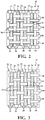
- the warp filaments 28 include substantially electrically non-conductive multifilaments 32 (the term "substantially” is intended to mean that although the multifilaments 32 could conduct a minimal electrical current, that one skilled in the art would consider the multifilaments 32 as being "non-conductive”) woven in a plain weave pattern with the weft filaments 30 and electrically conductive members 34 woven having a plurality of floats 36, with each of the floats 36 extending over at least two immediately adjacent ones of the weft filaments 30, and shown in one embodiment of the wall 12, as best shown in Figures 2 and 3 , extending over two weft filaments 30, thereby forming a twill-like float pattern, or, as shown in another embodiment of the wall 12', as best shown in Figures 2A and 3A , extending over more than two immediately adjacent ones of the weft filaments 30, thereby forming a satin-like float pattern.
- the floats 36 are shown as being formed to face radially inwardly toward the longitudinal central axis 18 along an inner surface 15 of the wall 12, 12', thereby avoiding the exposure of the floats 36 along an outer surface 13 of the wall 12, 12' to abrasion from external environmental elements. Accordingly, as will be recognized by the skilled artisan, the electrically conductive members 34, while being able to enhance protection against electrically generated interference, are protected against abrasion and wear due to the minimal exposure of the floats 36 to the outer surface 13 of the wall 12, 12', such that a majority of the length of the electrically conductive members 34 extends along the inner surface 15 of the wall 12, 12'. As such, the combination and synergies formed by the different warp filaments 32, 34 and different weave patterns formed thereby provide enhance protection to the elongate member 26 against abrasion and EMI, respectively.
- the opposite edges 14, 16 can be configured to be brought into automatic overlapping relation with one another by providing at least one or more, including all of the weft filaments 30 as a heat-settable polymeric filament, such as monofilaments of polyethylene terephthalate (PET) or polyphenylene sulfide (PPS), for example, which can be heat-set at a temperature between about 200-225 degrees Celsius.
- a heat-settable polymeric filament such as monofilaments of polyethylene terephthalate (PET) or polyphenylene sulfide (PPS), for example, which can be heat-set at a temperature between about 200-225 degrees Celsius.
- the elongate member 26 receives maximum protection from abrasion and any unwanted electrically generated interference, such as inductive interference, thereby providing any electrical components, such as control motors, for example, connected to the elongate member 26 with maximum operating functionality and efficiency.
- the sleeve 10 prevents the bundled elongate member 26 from interfering electrically with any adjacent electrical components.
- the substantially electrically non-conductive warp multifilaments 32 can be formed from, by way of example and without limitation, unplated polyester, nylon, polypropylene, polyethylene, acrylic, m-aramid (Nomex, Conex, Kermel), p-aramid (Kevlar, Twaron, Technora), PEI (Ultem), PPS, and PEEK, for example.
- the electrically conductive members 34 can be provided as metal-plated filaments, such as metal-plated multifilaments selected from the types of multifilaments mentioned above for the unplated non-conductive multifilaments.
- the unplated multifilaments 32 could include m-aramid multifilaments
- the metal-plated multifilaments 34 could include metal-plated m-aramid multifilaments, for example.
- the metal plating can be provided as copper and/or nickel and/or silver-based metal(s), including pure copper and/or pure nickel and/or pure silver, by way of example and without limitation.
- the metal-plated electrically conductive members 34 can be provided as metal-plated wire(s).
- the metal-plated electrically conductive members 34 can each include a plurality of continuous strands of wire filaments 38 that are metal-plated, such as a plurality of continuous strands of stainless steel wire filaments 38 plated with a metal-coating 40 of copper and/or nickel and/or silver-based metal, including pure copper, pure nickel and/or pure silver. It is contemplated herein that the number of wire filaments 38 within each metal-plated electrically conductive member 34 could range between about 10-30 continuous strands of wire filaments 38, with an exemplary embodiment including between about 15-20 wire filaments 38, thereby providing the conductive warp member 34 having a diameter between about 0.005-0.009 inches, by way of example and without limitation.
- wire filaments 38 can first be bundled, such as in a twisting or braiding process, by way of example and without limitation, and then plated with the selected metal, such as shown in Figure 4A , or, as shown in Figure 4B , the individual wire filaments 38 can be first plated with the selected metal and then bundled, such as in a twisting or braiding process, by way of example and without limitation.
- the unplated, substantially non-conductive warp multifilaments 32 and electrically conductive warp members 34 can be staggered with one another in alternating relation (every other warp filament 28 is a substantially non-conductive warp multifilament 32 and every other warp filament 28 is an electrically conductive member 34) about the entirety of the circumference of the sleeve 10 to provide optimal protection against both abrasion and EMI, RFI, ESD.
- the wall 12, 12' can have an organic or inorganic coating 35 applied thereto to lock or otherwise bond the filaments 28, 30 to one another, thereby maintaining the plated electrically conductive members 34 in their "as woven" relative location with one another.
- the spaces between alternating plated electrically conductive members 34 can be maintained, thus, assuring the optimal protection against EMI, RFI, ESD is maintained.
- the coating 35 acts to resist fraying and degradation of the unplated multifilaments, thereby enhancing their resistance to abrasion.
- a method of constructing a textile sleeve 10 for protecting elongate members 26 against abrasion, EMI, RFI, ESD includes forming a wall 12, 12' having opposite edges 14, 16 extending lengthwise in generally parallel relation with a longitudinal central axis 18 between open opposite ends 20, 22, with the opposite edges 14, 16 being configured to overlap one another to bound a central cavity 24 extending between the opposite ends 20, 22.
- forming the wall 12, 12' by weaving warp filaments 28 extending generally parallel to the longitudinal central axis 18 with weft filaments 30 extending generally transversely to the warp filaments 28, and further, weaving the warp filaments 28 including substantially electrically non-conductive multifilaments 32, as discussed above, woven in a plain weave pattern with the weft filaments 30 (undulating over a single (1) weft filament 30 and under an single (1) weft filament 30 in repeating fashion) and electrically conductive members 34, as discussed above, woven having a plurality of repetitive floats 36, with each float 36 extending over at least two ( Figures 2 and 3 ) or more ( Figures 2A and 3A ) immediately adjacent ones of the weft filaments 30, then under a single weft filament 30, then over at least two weft filaments 30 ( Figures 2 and 3 ) or more ( Figures 2A and 3A ), and so-on in repeating fashion.
- the method can further include weaving the floats 36 to extend along an inner surface 15 of the sleeve wall 12, 12' to avoid exposure of the floats 36 and the vast majority of the electrically conductive members 34 to abrasion from external environmental factors, whether from debris and/or neighboring cables, support members and the like. Further yet, the method can include heat-setting at least some or all of the weft filaments 30 to maintain the opposite edges 14, 16 in overlapped relation with one another to bound a central cavity 24 in which the elongate member 26 is received. Additionally, the method can include applying an organic or inorganic protective material coating 35 on the wall 12, 12' to enhance abrasion resistance and EMI protective capabilities thereof.
Landscapes
- Engineering & Computer Science (AREA)
- Textile Engineering (AREA)
- Physics & Mathematics (AREA)
- Electromagnetism (AREA)
- Microelectronics & Electronic Packaging (AREA)
- Architecture (AREA)
- Civil Engineering (AREA)
- Structural Engineering (AREA)
- Spectroscopy & Molecular Physics (AREA)
- Woven Fabrics (AREA)
- Chemical Or Physical Treatment Of Fibers (AREA)
- Shielding Devices Or Components To Electric Or Magnetic Fields (AREA)
- Details Of Indoor Wiring (AREA)
Description
- This invention relates generally to tubular sleeves for protecting elongate members, and more particularly to woven sleeves that provide protection to elongate members contained therein against abrasion and electromagnetic interference.
- It is known to shield wires against electromagnetic interference (EMI) and abrasion by disposing a protective textile sleeve and a separate outer abrasion resistant tube about the wires. Upon disposing the textile sleeve about the wires and then the abrasion resistant tube about the textile sleeve, the abrasion resistant tube can be heat-shrunk about the textile sleeve. Accordingly, the inner textile sleeve provides the EMI protection, while the heat-shrunk tube provides protection against abrasion. Although such textile sleeves and tubes can prove effective in shielding against EMI and providing protection against abrasion, they are costly from both a material and labor standpoint, having to essentially assembly two separate sleeves about the member being protected. Further yet, upon shrinking the tube about the sleeve, the assembly becomes relatively rigid and inflexible due to the heat-shrunk tubing contracting and hardening, thereby complicating the ability to route the wires over meandering paths and about corners. Further yet, the heat-shrunk tubing makes accessing the wires, such as during repair, difficult if not impossible without first destroying the sleeve.
-
WO2014/138742 discloses a textile sleeve having an electro-functional member interlaced therewith.WO2016/168794 discloses a textile sleeve for protecting a conductive member against one of EMI, RFI or ESD. - A protective sleeve manufactured in accordance with the present invention overcomes or greatly minimizes at least those limitations of the prior art described above, as will become readily appreciated by one skilled in the art upon viewing the disclosure herein.
- A textile sleeve for protecting elongate members against EMI is provided. The textile sleeve includes a wall having opposite edges extending lengthwise in generally parallel relation with a longitudinal axis between opposite ends. The opposite edges are configured to overlap one another to bound a central cavity extending between the opposite ends. The wall includes warp filaments, extending generally parallel to the longitudinal axis, woven with weft filaments, extending generally transversely to the warp filaments. The warp filaments include substantially electrically non-conductive multifilaments woven in a plain weave pattern with the weft filaments and electrically conductive members woven with the weft filaments, wherein the electrically conductive members form a plurality of floats, with each of the floats extending over at least two adjacent weft filaments. The sleeve is characterized in that said substantially electrically non-conductive multifilaments and said electrically conductive members are staggered with one another in alternating relation.
- In accordance with another aspect of the disclosure, the substantially electrically non-conductive warp multifilaments are unplated and the electrically conductive warp members are metal-plated.
- In accordance with another aspect of the disclosure, the metal-plated electrically conductive members can include metal-plated multifilaments.
- In accordance with another aspect of the disclosure, the metal-plated multifilaments can include metal-plated aramid multifilaments.
- In accordance with another aspect of the disclosure, separate ones of the metal-plated electrically conductive members can include a plurality of metal-plated wires.
- In accordance with another aspect of the disclosure, the wires of the plurality of metal-plated wires can include stainless steel wires.
- In accordance with another aspect of the disclosure, the wires of the plurality of metal-plated wires of each of the metal-plated electrically conductive members can be metal-plated individually and plied together.
- In accordance with another aspect of the disclosure, each of the metal-plated electrically conductive members can include between about 10-30 metal-plated metal wires.
- In accordance with another aspect of the disclosure, the metal-plated electrically conductive members can include an outer metal-plating of copper and/or nickel and/or silver.
- In accordance with another aspect of the disclosure, the substantially electrically non-conductive multifilaments can be provided including multifilaments of aramid material.
- In accordance with another aspect of the disclosure, an organic or inorganic coating can be applied on the warp and weft filaments to bond the warp and weft filaments together.
- In accordance with another aspect of the disclosure, the warp metal-plated electrically conductive members can be woven in a twill pattern.
- In accordance with another aspect of the disclosure, the warp metal-plated electrically conductive members can be woven in a satin pattern.
- In accordance with another aspect of the disclosure, the floats of the warp metal-plated electrically conductive members can be woven to face radially inwardly toward the cavity to both provide efficient shielding against electromagnetic interferences and to avoid being abraded by elements external to the cavity.
- In accordance with another aspect of the disclosure, at least some or all of the weft filaments include heat-set filaments biasing the opposite edges into overlapping relation with one another.
- In accordance with another aspect of the disclosure, a method of constructing a textile sleeve for protecting elongate members against abrasion and EMI is provided. The method includes forming a wall having opposite edges extending lengthwise in generally parallel relation with a longitudinal axis extending between opposite ends, with the opposite edges being configured to overlap one another to bound a central cavity extending between the opposite ends. Further, forming the wall by weaving warp filaments extending generally parallel to the longitudinal axis with weft filaments extending generally transversely to the warp filaments. Further yet, weaving the warp filaments including substantially electrically non-conductive multifilaments woven in a plain weave pattern with the weft filaments, and weaving the warp filaments including electrically conductive members forming floats extending over at least two of the weft filaments. The method is characterized by weaving said substantially electrically non-conductive multifilaments and said electrically conductive members in staggered, alternating relation with one another
- In accordance with another aspect of the disclosure, the method can further include providing the substantially electrically non-conductive multifilaments as unplated multifilaments and providing the electrically conductive members as metal-plated electrically conductive members.
- In accordance with another aspect of the disclosure, the method can further include providing the unplated multifilaments as aramid multifilaments.
- In accordance with another aspect of the disclosure, the method can further include providing the metal-plated electrically conductive members as metal-plated multifilaments.
- In accordance with another aspect of the disclosure, the method can further include providing the metal-plated multifilaments as plated aramid multifilaments.
- In accordance with another aspect of the invention, the method can further include providing each of the metal-plated electrically conductive members including a plurality of continuous wire filaments.
- In accordance with another aspect of the disclosure, the method can further include providing the plurality of continuous wire filaments within each metal-plated electrically conductive member including stainless steel wire filaments.
- In accordance with another aspect of the disclosure, the method can further include providing each of the metal-plated electrically conductive members having between about 10-30 metal-plated metal wire filaments bundled together.
- In accordance with another aspect of the disclosure, the method can further include providing the metal-plated electrically conductive members as metal-plated stainless steel wire.
- In accordance with another aspect of the disclosure, the method can further include providing the plurality of wires within each metal-plated electrically conductive member being plied together.
- In accordance with another aspect of the disclosure, the method can further include providing the metal plating including copper and/or nickel and/or silver.
- In accordance with another aspect of the disclosure, the method can further include applying an organic or inorganic coating on the warp and weft filaments to bond the warp and weft filaments with one another.
- In accordance with another aspect of the disclosure, the method can further include weaving the metal-plated electrically conductive members in a twill pattern.
- In accordance with another aspect of the disclosure, the method can further include weaving the metal-plated electrically conductive members in a satin pattern.
- In accordance with another aspect of the disclosure, the method can further include forming the floats of the metal-plated electrically conductive members to face radially inwardly into the cavity.
- In accordance with another aspect of the disclosure, the method can further include weaving the non-conductive warp multifilaments and the electrically conductive warp members in staggered, alternating relation with one another such that every other warp filament is formed by one of the non-conductive warp multifilaments and every other warp filament is formed by one of the electrically conductive warp members.
- In accordance with another aspect of the disclosure, the method can further include heat-setting at least some or all of the weft filaments to bias the opposite edges into overlapping relation with one another.
- These and other aspects, features and advantages will become readily apparent to those skilled in the art in view of the following detailed description of the presently preferred embodiments and best mode, appended claims, and accompanying drawings, in which:
-
Figure 1 is a schematic perspective view of a self-wrapping sleeve constructed in accordance with one presently preferred embodiment of the disclosure; -
Figure 2 is an enlarged fragmentary view of an outer surface of a wall of the sleeve ofFigure 1 constructed in accordance with one aspect of the disclosure; -
Figure 2A is an enlarged fragmentary view of an outer surface of a wall of the sleeve ofFigure 1 constructed in accordance with another aspect of the disclosure; -
Figure 3 is an enlarged fragmentary view of an inner surface of the wall ofFigure 2 ; -
Figure 3A is an enlarged fragmentary view of an inner surface of the wall ofFigure 2A ; -
Figure 4A is an enlarged schematic perspective view of an electrically conductive warp member in accordance in accordance with one aspect of the disclosure; and -
Figure 4B is a view similar toFigure 4A of an electrically conductive warp member in accordance in accordance with another aspect of the disclosure. - Referring in more detail to the drawings,
Figure 1 shows a self-wrappingsleeve 10 constructed according in accordance with one presently preferred aspect of the disclosure. Thesleeve 10 has awall 12, 12' (two different embodiments discussed below, with the only difference being a weave pattern) withopposite edges central axis 18 between opposite ends 20, 22. The opposite edges 14, 16 are configured to be wrapped to overlap one another to bound a circumferentiallyenclosed cavity 24, with theopposite edges enclosed cavity 24 extending lengthwise between the opposite ends 20, 22, wherein thecavity 24 is sized for protective receipt of an elongate member or members to be protected therein, shown as a cable or awire harness 26, by way of example and without limitation. Thesleeve 10 is particularly well-suited for providing protection to theelongate member 26 against electromagnetic interference (EMI), radio frequency interference (RFI), and/or electrostatic discharge (ESD), as well as against contamination and abrasion. Thewall 12, 12' is formed from a plurality of filaments woven with one another, wherein the term filaments is intended to include monofilaments and/or multifilaments, with specific reference being given to the type of filament, as necessary, hereafter, wherein the term "yarn" is used herein to reference both monofilaments and multifilaments. Thewall 12, 12' includeswarp filaments 28 extending parallel or generally parallel to the longitudinal central axis 18 (generally parallel is intended to mean that the filaments could be less than truly parallel to the longitudinalcentral axis 18, but that to the naked eye one skilled in the art would commonly refer to the filaments as extending parallel to one another and to the longitudinal central axis 18) woven withweft filaments 30 extending generally transversely to thewarp filaments 28. Thewarp filaments 28 include substantially electrically non-conductive multifilaments 32 (the term "substantially" is intended to mean that although themultifilaments 32 could conduct a minimal electrical current, that one skilled in the art would consider themultifilaments 32 as being "non-conductive") woven in a plain weave pattern with theweft filaments 30 and electricallyconductive members 34 woven having a plurality offloats 36, with each of thefloats 36 extending over at least two immediately adjacent ones of theweft filaments 30, and shown in one embodiment of thewall 12, as best shown inFigures 2 and 3 , extending over twoweft filaments 30, thereby forming a twill-like float pattern, or, as shown in another embodiment of the wall 12', as best shown inFigures 2A and 3A , extending over more than two immediately adjacent ones of theweft filaments 30, thereby forming a satin-like float pattern. The floats 36 are shown as being formed to face radially inwardly toward the longitudinalcentral axis 18 along an inner surface 15 of thewall 12, 12', thereby avoiding the exposure of thefloats 36 along anouter surface 13 of thewall 12, 12' to abrasion from external environmental elements. Accordingly, as will be recognized by the skilled artisan, the electricallyconductive members 34, while being able to enhance protection against electrically generated interference, are protected against abrasion and wear due to the minimal exposure of thefloats 36 to theouter surface 13 of thewall 12, 12', such that a majority of the length of the electricallyconductive members 34 extends along the inner surface 15 of thewall 12, 12'. As such, the combination and synergies formed by thedifferent warp filaments elongate member 26 against abrasion and EMI, respectively. - With the
wall 12, 12' being formed as an "open" sleeve, theopposite edges weft filaments 30 as a heat-settable polymeric filament, such as monofilaments of polyethylene terephthalate (PET) or polyphenylene sulfide (PPS), for example, which can be heat-set at a temperature between about 200-225 degrees Celsius. Once enclosed within thecavity 24 of thesleeve 10, theelongate member 26 receives maximum protection from abrasion and any unwanted electrically generated interference, such as inductive interference, thereby providing any electrical components, such as control motors, for example, connected to theelongate member 26 with maximum operating functionality and efficiency. In addition, thesleeve 10 prevents the bundledelongate member 26 from interfering electrically with any adjacent electrical components. - Depending on the application, the substantially electrically
non-conductive warp multifilaments 32 can be formed from, by way of example and without limitation, unplated polyester, nylon, polypropylene, polyethylene, acrylic, m-aramid (Nomex, Conex, Kermel), p-aramid (Kevlar, Twaron, Technora), PEI (Ultem), PPS, and PEEK, for example. Meanwhile, the electricallyconductive members 34 can be provided as metal-plated filaments, such as metal-plated multifilaments selected from the types of multifilaments mentioned above for the unplated non-conductive multifilaments. Accordingly, by way of example, theunplated multifilaments 32 could include m-aramid multifilaments, while the metal-platedmultifilaments 34 could include metal-plated m-aramid multifilaments, for example. The metal plating can be provided as copper and/or nickel and/or silver-based metal(s), including pure copper and/or pure nickel and/or pure silver, by way of example and without limitation. Further yet, the metal-plated electricallyconductive members 34 can be provided as metal-plated wire(s). Accordingly, as shown inFigures 4A and 4B , the metal-plated electricallyconductive members 34 can each include a plurality of continuous strands ofwire filaments 38 that are metal-plated, such as a plurality of continuous strands of stainlesssteel wire filaments 38 plated with a metal-coating 40 of copper and/or nickel and/or silver-based metal, including pure copper, pure nickel and/or pure silver. It is contemplated herein that the number ofwire filaments 38 within each metal-plated electricallyconductive member 34 could range between about 10-30 continuous strands ofwire filaments 38, with an exemplary embodiment including between about 15-20wire filaments 38, thereby providing theconductive warp member 34 having a diameter between about 0.005-0.009 inches, by way of example and without limitation. It is further contemplated that thewire filaments 38 can first be bundled, such as in a twisting or braiding process, by way of example and without limitation, and then plated with the selected metal, such as shown inFigure 4A , or, as shown inFigure 4B , theindividual wire filaments 38 can be first plated with the selected metal and then bundled, such as in a twisting or braiding process, by way of example and without limitation. The unplated, substantiallynon-conductive warp multifilaments 32 and electricallyconductive warp members 34 can be staggered with one another in alternating relation (everyother warp filament 28 is a substantially non-conductive warp multifilament 32 and everyother warp filament 28 is an electrically conductive member 34) about the entirety of the circumference of thesleeve 10 to provide optimal protection against both abrasion and EMI, RFI, ESD. To further enhance maintaining the desired abrasion resistance and EMI protection, thewall 12, 12' can have an organic orinorganic coating 35 applied thereto to lock or otherwise bond thefilaments conductive members 34 in their "as woven" relative location with one another. As such, the spaces between alternating plated electricallyconductive members 34 can be maintained, thus, assuring the optimal protection against EMI, RFI, ESD is maintained. Further, thecoating 35 acts to resist fraying and degradation of the unplated multifilaments, thereby enhancing their resistance to abrasion. - In accordance with another aspect of the disclosure, a method of constructing a
textile sleeve 10 for protectingelongate members 26 against abrasion, EMI, RFI, ESD is provided. The method includes forming awall 12, 12' havingopposite edges central axis 18 between open opposite ends 20, 22, with theopposite edges central cavity 24 extending between the opposite ends 20, 22. Further, forming thewall 12, 12' by weavingwarp filaments 28 extending generally parallel to the longitudinalcentral axis 18 withweft filaments 30 extending generally transversely to thewarp filaments 28, and further, weaving thewarp filaments 28 including substantially electricallynon-conductive multifilaments 32, as discussed above, woven in a plain weave pattern with the weft filaments 30 (undulating over a single (1)weft filament 30 and under an single (1)weft filament 30 in repeating fashion) and electricallyconductive members 34, as discussed above, woven having a plurality ofrepetitive floats 36, with eachfloat 36 extending over at least two (Figures 2 and 3 ) or more (Figures 2A and 3A ) immediately adjacent ones of theweft filaments 30, then under asingle weft filament 30, then over at least two weft filaments 30 (Figures 2 and 3 ) or more (Figures 2A and 3A ), and so-on in repeating fashion. The method can further include weaving thefloats 36 to extend along an inner surface 15 of thesleeve wall 12, 12' to avoid exposure of thefloats 36 and the vast majority of the electricallyconductive members 34 to abrasion from external environmental factors, whether from debris and/or neighboring cables, support members and the like. Further yet, the method can include heat-setting at least some or all of theweft filaments 30 to maintain theopposite edges central cavity 24 in which theelongate member 26 is received. Additionally, the method can include applying an organic or inorganicprotective material coating 35 on thewall 12, 12' to enhance abrasion resistance and EMI protective capabilities thereof. - Obviously, many modifications and variations of the present invention are possible in light of the above teachings. It is, therefore, to be understood that within the scope of the appended claims, the invention may be practiced otherwise than as specifically described, and that is contemplated that all features of all claims and of all embodiments can be combined with each other, so long as such combinations would not contradict one another.
Claims (15)
- A textile sleeve (10) for protecting elongate members (26) against abrasion and EMI, comprising:a wall (12, 12') having opposite edges (14, 16) extending lengthwise in generally parallel relation with a longitudinal axis (18) between opposite ends (20, 22), said opposite edges (14, 16) being configured to overlap one another to bound an enclosed cavity (24) extending between said opposite ends (20, 22), said wall having warp filaments (28) extending generally parallel to said longitudinal axis (18) woven with weft filaments (30) extending generally transversely to said warp filaments (28), said warp filaments (28) including substantially electrically non-conductive multifilaments (32) woven in a plain weave pattern with said weft filaments (30) and electrically conductive members (34) woven with said weft filaments (30), wherein said electrically conductive members (34) form a plurality of floats (36), with each of said floats (36) extending over at least two adjacent ones of said weft filaments (30);characterized in that said substantially electrically non-conductive multifilaments (32) and said electrically conductive members (34) are staggered with one another in alternating relation.
- The textile sleeve (10) of claim 1, wherein said electrically conductive members (34) are metal-plated.
- The textile sleeve (10) of claim 2, wherein said metal-plated electrically conductive members (34) are metal-plated multifilaments.
- The textile sleeve (10) of claim 3, wherein said metal-plated multifilaments include metal-plated multifilaments of aramid.
- The textile sleeve (10) of claim 2, wherein separate ones of said metal-plated electrically conductive members (34) include a plurality of metal-plated wires (38).
- The textile sleeve of claim 5, wherein said metal-plated wires (38) include metal-plated stainless steel wires or each of said plurality of metal-plated wires (38) includes between about 10-30 metal plated wires.
- The textile sleeve (10) of claim 2, wherein said metal-plated electrically conductive members (34) include an outer plating of at least one of copper, nickel and silver.
- The textile sleeve (10) of claim 1, further including an organic or inorganic coating (35) bonding said warp (28) and weft filaments (30) together.
- The textile sleeve of claim 1, wherein said floats (36) face radially inwardly toward the cavity (24) or said weft filaments (30) include heat-set filaments biasing said opposite edges into overlapping relation with one another.
- A method of constructing a textile sleeve (10) for protecting elongate members (26) against abrasion and EMI, comprising:forming a wall having opposite edges (14, 16) extending lengthwise in generally parallel relation with a longitudinal axis (18) between opposite ends (20, 22), with said opposite edges (14, 16) being configured to overlap one another to bound a central cavity (24) extending between said opposite ends (20, 22);forming said wall by weaving warp filaments (28) extending generally parallel to said longitudinal axis (18) with weft filaments (30) extending generally transversely to said warp filaments (28);weaving said warp filaments (28) including substantially electrically non-conductive multifilaments (32) woven in a plain weave pattern with said weft filaments (30) and including electrically conductive members (34) forming a plurality of floats (36), with each of said floats (36) extending over at least two adjacent ones of said weft filaments (30); andthe method being characterized by:
weaving said substantially electrically non-conductive multifilaments (32) and said electrically conductive members (34) in staggered, alternating relation with one another. - The method of claim 10, further including providing said substantially electrically non-conductive multifilaments (32) as aramid multifilaments.
- The method of claim 10, further including providing said electrically conductive members (34) as metal-plated filaments.
- The method of claim 12, further including providing said metal-plated filaments including metal-plated aramid multifilaments or metal-plated wire filaments (38) or metal-plated stainless steel wire filaments.
- The method of claim 12, further including providing said metal-plated filaments including an outer plating of at least one of copper, nickel and silver.
- The method of claim 10, further including one of:applying an organic or inorganic coating (35) on said warp (28) and weft filaments (30) to bond said warp (28) and weft filaments (30) with one another;weaving said electrically conductive members in a twill pattern;weaving said electrically conductive members in a satin pattern;forming said floats to face radially inwardly into the cavity; andheat-setting at least some of said weft filaments to bias said opposite edges into overlapping relation with one another.
Applications Claiming Priority (3)
| Application Number | Priority Date | Filing Date | Title |
|---|---|---|---|
| US201762481595P | 2017-04-04 | 2017-04-04 | |
| US15/944,708 US10615581B2 (en) | 2017-04-04 | 2018-04-03 | Woven EMI and abrasion resistant sleeve and method of construction thereof |
| PCT/US2018/025977 WO2018187393A1 (en) | 2017-04-04 | 2018-04-04 | Woven emi and abrasion resistant sleeve and method of construction thereof |
Publications (2)
| Publication Number | Publication Date |
|---|---|
| EP3607119A1 EP3607119A1 (en) | 2020-02-12 |
| EP3607119B1 true EP3607119B1 (en) | 2021-11-10 |
Family
ID=63671069
Family Applications (1)
| Application Number | Title | Priority Date | Filing Date |
|---|---|---|---|
| EP18720825.1A Not-in-force EP3607119B1 (en) | 2017-04-04 | 2018-04-04 | Woven emi and abrasion resistant sleeve and method of construction thereof |
Country Status (5)
| Country | Link |
|---|---|
| US (1) | US10615581B2 (en) |
| EP (1) | EP3607119B1 (en) |
| JP (1) | JP7135000B2 (en) |
| CN (1) | CN110651076B (en) |
| WO (1) | WO2018187393A1 (en) |
Families Citing this family (11)
| Publication number | Priority date | Publication date | Assignee | Title |
|---|---|---|---|---|
| US10615581B2 (en) * | 2017-04-04 | 2020-04-07 | Federal-Mogul Powertrain, Llc | Woven EMI and abrasion resistant sleeve and method of construction thereof |
| CN114375353B (en) * | 2019-09-10 | 2023-08-11 | 费德罗-莫格尔动力系公司 | Corrugated woven sleeve and method of making same |
| US11219145B2 (en) * | 2019-11-05 | 2022-01-04 | Ls Cable & System Ltd. | Self-wrap electromagnetic wave shield tube |
| KR102722894B1 (en) * | 2019-11-07 | 2024-10-25 | 엘에스전선 주식회사 | Self-Wrap Electromagnetic Wave Shield Tube |
| CN111130031A (en) * | 2019-11-15 | 2020-05-08 | 安徽光复电缆有限公司 | Aerospace is with formula of rolling up opening shielding protective sheath certainly |
| US12296762B2 (en) * | 2020-02-20 | 2025-05-13 | Sumitomo Wiring Systems, Ltd. | Wire harness |
| US12281417B2 (en) * | 2022-01-26 | 2025-04-22 | Federal-Mogul Powertrain Llc | Self-wrapping woven sleeve with wear indicator yarns and method of construction thereof |
| EP4372134A1 (en) * | 2022-11-21 | 2024-05-22 | Tyco Electronics UK Ltd | Heat-shrink fabric tubing and method of constructing a heat-shrink fabric tubing |
| US12460324B2 (en) * | 2023-04-21 | 2025-11-04 | Systems Protection Group Us Llc | Wrappable, woven, abrasion and EMI resistant sleeve |
| US12156392B1 (en) * | 2023-07-11 | 2024-11-26 | Federal-Mogul Powertrain Llc | Self-wrapping, multilayer abrasion and EMI resistant sleeve and method of construction thereof |
| US20250309625A1 (en) * | 2024-04-02 | 2025-10-02 | Federal-Mogul Powertrain Llc | Multilayer, emi shielding, self-wrapping textile sleeve and method of construction thereof |
Family Cites Families (35)
| Publication number | Priority date | Publication date | Assignee | Title |
|---|---|---|---|---|
| US4606968A (en) * | 1983-07-25 | 1986-08-19 | Stern And Stern Textiles, Inc. | Electrostatic dissipating fabric |
| US4557968A (en) * | 1983-07-25 | 1985-12-10 | Stern & Stern Textiles, Inc. | Directional electrostatic dissipating fabric and method |
| US4741087A (en) * | 1983-09-16 | 1988-05-03 | Plummer Jr Walter A | Method of making pre-expanded braided sleeving |
| JPS61137682U (en) * | 1985-02-14 | 1986-08-27 | ||
| US5229176A (en) | 1991-06-04 | 1993-07-20 | Minnesota Mining And Manufacturing Company | Protective sleeve and method of assembling the protective sleeve to an object to be protected |
| US5827997A (en) * | 1994-09-30 | 1998-10-27 | Chung; Deborah D. L. | Metal filaments for electromagnetic interference shielding |
| US6045884A (en) * | 1996-02-27 | 2000-04-04 | Federal-Mogul Systems Protection Group, Inc. | Thermally protective sleeving |
| US5889229A (en) * | 1997-03-18 | 1999-03-30 | Instrument Specialties Co., Inc. | Self-terminating, knitted, metalized yarn EMI/RFI shielding gasket |
| JP3519290B2 (en) * | 1998-11-05 | 2004-04-12 | カネボウ株式会社 | Electromagnetic shielding fabric |
| EP1205589B1 (en) * | 1999-05-24 | 2011-11-02 | Gunze Limited | Electro-magnetic wave shielding knitted material and electro-magnetic wave shielding clothes |
| US6639148B2 (en) * | 2001-06-20 | 2003-10-28 | Federal-Mogul Systems Protection Group, Inc. | Extendible drain members for grounding RFI/EMI shielding |
| BRPI0313874B1 (en) | 2002-08-28 | 2016-03-15 | Federal Mogul Powertrain Inc | elongated sleeve structure, mounting to receive elongated items, and method for positioning and securing elongated items within a duct |
| JP2005093010A (en) * | 2003-09-19 | 2005-04-07 | Ricoh Co Ltd | Recording apparatus, recording method, and program |
| CN1984770B (en) * | 2004-06-18 | 2011-04-20 | 特克斯特龙尼克斯公司 | Functional elastic textile structure |
| US8283563B2 (en) * | 2006-03-29 | 2012-10-09 | Federal-Mogul Powertrain, Inc. | Protective sleeve fabricated with hybrid yard, hybrid yarn, and methods of construction thereof |
| US7576286B2 (en) * | 2006-03-29 | 2009-08-18 | Federal-Mogul World Wide, Inc. | Protective sleeve fabricated with hybrid yarn having wire filaments and methods of construction |
| US20070243356A1 (en) * | 2006-04-17 | 2007-10-18 | Baer Angela L | Self folding low-profile textile sleeve for protecting elongate members and method of construction |
| CN102667964B (en) * | 2009-10-07 | 2015-06-17 | 费德罗-莫格尔动力系公司 | Flexible textile sleeve with end fray resistant, protective coating and method of construction thereof |
| JP5794768B2 (en) * | 2010-07-26 | 2015-10-14 | 矢崎総業株式会社 | Wire harness shielded exterior |
| WO2012024272A1 (en) * | 2010-08-16 | 2012-02-23 | Federal-Mogul Powertrain, Inc. | Non-kinking self-wrapping woven sleeve and method of construction thereof |
| US9635790B2 (en) * | 2012-03-13 | 2017-04-25 | Parker-Hannifin Corporation | Deflectable conductive gasket with environmental seal |
| US9478954B2 (en) * | 2012-04-11 | 2016-10-25 | Federal-Mogul Powertrain, Inc. | Self-curling non-woven sleeve and method of construction thereof |
| KR102145648B1 (en) * | 2013-02-04 | 2020-08-18 | 페더럴-모걸 파워트레인 엘엘씨 | Non-kinking self-wrapping woven sleeve and method of construction thereof |
| BR112015021519A2 (en) * | 2013-03-08 | 2017-07-18 | Fed Mogul Powertrain Inc | wrapping sleeve with extendable electrofunctional wire conductors and method of construction thereof |
| WO2014159821A1 (en) * | 2013-03-13 | 2014-10-02 | Federal-Mogul Powertrain, Inc. | Self-wrappable eptfe textile sleeve and method of construction thereof |
| US9913415B2 (en) * | 2013-03-13 | 2018-03-06 | Federal-Mogul Powertrain Llc | EMI shielding textile fabric, wrappable sleeve constructed therefrom and method of construction thereof |
| US10132012B2 (en) * | 2013-03-14 | 2018-11-20 | Federal-Mogul Powertrain Llc | End-fray resistant heat-shrinkable woven sleeve, assembly therewith and methods of construction thereof |
| RU2666855C2 (en) * | 2013-08-26 | 2018-09-12 | Федерал-Могал Пауэртрейн, Инк. | Protective textile sleeve, method of manufacture and use thereof |
| US9307685B2 (en) | 2014-07-16 | 2016-04-05 | Federal-Mogul Powertrain, Inc. | Protective sleeve with bonded wire filaments and methods of construction thereof |
| US10202714B2 (en) * | 2014-10-30 | 2019-02-12 | Federal-Mogul Powertrain Llc | Braided textile sleeve with self-sustaining expanded and contracted states and method of construction thereof |
| GB2550709B (en) | 2014-12-24 | 2021-03-10 | Commw Scient Ind Res Org | An electrically conductive textile |
| US10542645B2 (en) | 2015-04-17 | 2020-01-21 | Federal-Mogul Powertrain Llc | EMI protective sleeve and method of construction thereof |
| US11268217B2 (en) * | 2015-12-18 | 2022-03-08 | Federal-Mogul Powertrain Llc | Wrappable end fray resistant woven protective textile sleeve and method of construction thereof |
| US12051527B2 (en) * | 2016-01-20 | 2024-07-30 | Federal-Mogul Powertrain Llc | Abrasion resistant textile sleeve, improved multifilament yarn therefor and methods of construction thereof |
| US10615581B2 (en) * | 2017-04-04 | 2020-04-07 | Federal-Mogul Powertrain, Llc | Woven EMI and abrasion resistant sleeve and method of construction thereof |
-
2018
- 2018-04-03 US US15/944,708 patent/US10615581B2/en not_active Expired - Fee Related
- 2018-04-04 WO PCT/US2018/025977 patent/WO2018187393A1/en not_active Ceased
- 2018-04-04 CN CN201880027334.4A patent/CN110651076B/en not_active Expired - Fee Related
- 2018-04-04 EP EP18720825.1A patent/EP3607119B1/en not_active Not-in-force
- 2018-04-04 JP JP2019554700A patent/JP7135000B2/en active Active
Non-Patent Citations (1)
| Title |
|---|
| None * |
Also Published As
| Publication number | Publication date |
|---|---|
| JP7135000B2 (en) | 2022-09-12 |
| CN110651076B (en) | 2021-08-20 |
| EP3607119A1 (en) | 2020-02-12 |
| WO2018187393A1 (en) | 2018-10-11 |
| US10615581B2 (en) | 2020-04-07 |
| US20180287357A1 (en) | 2018-10-04 |
| JP2020515735A (en) | 2020-05-28 |
| CN110651076A (en) | 2020-01-03 |
Similar Documents
| Publication | Publication Date | Title |
|---|---|---|
| US10615581B2 (en) | Woven EMI and abrasion resistant sleeve and method of construction thereof | |
| EP2971301B1 (en) | Emi shielding textile fabric, wrappable sleeve constructed therefrom and method of construction thereof | |
| US10149418B2 (en) | Protective sleeve with bonded wire filaments and methods of construction thereof | |
| EP2474007B1 (en) | Protective sleeve fabricated with hybrid yarn | |
| KR102565498B1 (en) | EMI shielding sleeve and its manufacturing method | |
| EP1999762B1 (en) | Protective sleeve fabricated with hybrid yarn having wire filaments and method of fabrication | |
| EP3169837B1 (en) | Protective sleeve with bonded wire filaments and methods of construction thereof | |
| US12156392B1 (en) | Self-wrapping, multilayer abrasion and EMI resistant sleeve and method of construction thereof | |
| US20250309625A1 (en) | Multilayer, emi shielding, self-wrapping textile sleeve and method of construction thereof | |
| US12630949B2 (en) | EMI protective sleeve and method of construction thereof |
Legal Events
| Date | Code | Title | Description |
|---|---|---|---|
| STAA | Information on the status of an ep patent application or granted ep patent |
Free format text: STATUS: UNKNOWN |
|
| STAA | Information on the status of an ep patent application or granted ep patent |
Free format text: STATUS: THE INTERNATIONAL PUBLICATION HAS BEEN MADE |
|
| PUAI | Public reference made under article 153(3) epc to a published international application that has entered the european phase |
Free format text: ORIGINAL CODE: 0009012 |
|
| STAA | Information on the status of an ep patent application or granted ep patent |
Free format text: STATUS: REQUEST FOR EXAMINATION WAS MADE |
|
| 17P | Request for examination filed |
Effective date: 20191004 |
|
| AK | Designated contracting states |
Kind code of ref document: A1 Designated state(s): AL AT BE BG CH CY CZ DE DK EE ES FI FR GB GR HR HU IE IS IT LI LT LU LV MC MK MT NL NO PL PT RO RS SE SI SK SM TR |
|
| AX | Request for extension of the european patent |
Extension state: BA ME |
|
| DAV | Request for validation of the european patent (deleted) | ||
| DAX | Request for extension of the european patent (deleted) | ||
| STAA | Information on the status of an ep patent application or granted ep patent |
Free format text: STATUS: EXAMINATION IS IN PROGRESS |
|
| 17Q | First examination report despatched |
Effective date: 20201007 |
|
| REG | Reference to a national code |
Ref country code: DE Ref legal event code: R079 Ref document number: 602018026441 Country of ref document: DE Free format text: PREVIOUS MAIN CLASS: D03D0015020000 Ipc: D03D0001000000 |
|
| GRAP | Despatch of communication of intention to grant a patent |
Free format text: ORIGINAL CODE: EPIDOSNIGR1 |
|
| STAA | Information on the status of an ep patent application or granted ep patent |
Free format text: STATUS: GRANT OF PATENT IS INTENDED |
|
| RIC1 | Information provided on ipc code assigned before grant |
Ipc: D03D 1/00 20060101AFI20210521BHEP Ipc: H01B 3/50 20060101ALI20210521BHEP Ipc: H01R 13/6581 20110101ALI20210521BHEP Ipc: H02G 15/18 20060101ALI20210521BHEP Ipc: H05K 9/00 20060101ALI20210521BHEP Ipc: D03D 15/533 20210101ALI20210521BHEP Ipc: H02G 3/04 20060101ALI20210521BHEP |
|
| INTG | Intention to grant announced |
Effective date: 20210615 |
|
| GRAS | Grant fee paid |
Free format text: ORIGINAL CODE: EPIDOSNIGR3 |
|
| GRAA | (expected) grant |
Free format text: ORIGINAL CODE: 0009210 |
|
| STAA | Information on the status of an ep patent application or granted ep patent |
Free format text: STATUS: THE PATENT HAS BEEN GRANTED |
|
| AK | Designated contracting states |
Kind code of ref document: B1 Designated state(s): AL AT BE BG CH CY CZ DE DK EE ES FI FR GB GR HR HU IE IS IT LI LT LU LV MC MK MT NL NO PL PT RO RS SE SI SK SM TR |
|
| REG | Reference to a national code |
Ref country code: GB Ref legal event code: FG4D |
|
| REG | Reference to a national code |
Ref country code: AT Ref legal event code: REF Ref document number: 1446177 Country of ref document: AT Kind code of ref document: T Effective date: 20211115 Ref country code: CH Ref legal event code: EP |
|
| REG | Reference to a national code |
Ref country code: DE Ref legal event code: R096 Ref document number: 602018026441 Country of ref document: DE |
|
| REG | Reference to a national code |
Ref country code: IE Ref legal event code: FG4D |
|
| REG | Reference to a national code |
Ref country code: LT Ref legal event code: MG9D |
|
| REG | Reference to a national code |
Ref country code: NL Ref legal event code: MP Effective date: 20211110 |
|
| REG | Reference to a national code |
Ref country code: AT Ref legal event code: MK05 Ref document number: 1446177 Country of ref document: AT Kind code of ref document: T Effective date: 20211110 |
|
| PG25 | Lapsed in a contracting state [announced via postgrant information from national office to epo] |
Ref country code: RS Free format text: LAPSE BECAUSE OF FAILURE TO SUBMIT A TRANSLATION OF THE DESCRIPTION OR TO PAY THE FEE WITHIN THE PRESCRIBED TIME-LIMIT Effective date: 20211110 Ref country code: LT Free format text: LAPSE BECAUSE OF FAILURE TO SUBMIT A TRANSLATION OF THE DESCRIPTION OR TO PAY THE FEE WITHIN THE PRESCRIBED TIME-LIMIT Effective date: 20211110 Ref country code: FI Free format text: LAPSE BECAUSE OF FAILURE TO SUBMIT A TRANSLATION OF THE DESCRIPTION OR TO PAY THE FEE WITHIN THE PRESCRIBED TIME-LIMIT Effective date: 20211110 Ref country code: BG Free format text: LAPSE BECAUSE OF FAILURE TO SUBMIT A TRANSLATION OF THE DESCRIPTION OR TO PAY THE FEE WITHIN THE PRESCRIBED TIME-LIMIT Effective date: 20220210 Ref country code: AT Free format text: LAPSE BECAUSE OF FAILURE TO SUBMIT A TRANSLATION OF THE DESCRIPTION OR TO PAY THE FEE WITHIN THE PRESCRIBED TIME-LIMIT Effective date: 20211110 |
|
| PG25 | Lapsed in a contracting state [announced via postgrant information from national office to epo] |
Ref country code: IS Free format text: LAPSE BECAUSE OF FAILURE TO SUBMIT A TRANSLATION OF THE DESCRIPTION OR TO PAY THE FEE WITHIN THE PRESCRIBED TIME-LIMIT Effective date: 20220310 Ref country code: SE Free format text: LAPSE BECAUSE OF FAILURE TO SUBMIT A TRANSLATION OF THE DESCRIPTION OR TO PAY THE FEE WITHIN THE PRESCRIBED TIME-LIMIT Effective date: 20211110 Ref country code: PT Free format text: LAPSE BECAUSE OF FAILURE TO SUBMIT A TRANSLATION OF THE DESCRIPTION OR TO PAY THE FEE WITHIN THE PRESCRIBED TIME-LIMIT Effective date: 20220310 Ref country code: PL Free format text: LAPSE BECAUSE OF FAILURE TO SUBMIT A TRANSLATION OF THE DESCRIPTION OR TO PAY THE FEE WITHIN THE PRESCRIBED TIME-LIMIT Effective date: 20211110 Ref country code: NO Free format text: LAPSE BECAUSE OF FAILURE TO SUBMIT A TRANSLATION OF THE DESCRIPTION OR TO PAY THE FEE WITHIN THE PRESCRIBED TIME-LIMIT Effective date: 20220210 Ref country code: NL Free format text: LAPSE BECAUSE OF FAILURE TO SUBMIT A TRANSLATION OF THE DESCRIPTION OR TO PAY THE FEE WITHIN THE PRESCRIBED TIME-LIMIT Effective date: 20211110 Ref country code: LV Free format text: LAPSE BECAUSE OF FAILURE TO SUBMIT A TRANSLATION OF THE DESCRIPTION OR TO PAY THE FEE WITHIN THE PRESCRIBED TIME-LIMIT Effective date: 20211110 Ref country code: HR Free format text: LAPSE BECAUSE OF FAILURE TO SUBMIT A TRANSLATION OF THE DESCRIPTION OR TO PAY THE FEE WITHIN THE PRESCRIBED TIME-LIMIT Effective date: 20211110 Ref country code: GR Free format text: LAPSE BECAUSE OF FAILURE TO SUBMIT A TRANSLATION OF THE DESCRIPTION OR TO PAY THE FEE WITHIN THE PRESCRIBED TIME-LIMIT Effective date: 20220211 Ref country code: ES Free format text: LAPSE BECAUSE OF FAILURE TO SUBMIT A TRANSLATION OF THE DESCRIPTION OR TO PAY THE FEE WITHIN THE PRESCRIBED TIME-LIMIT Effective date: 20211110 |
|
| PG25 | Lapsed in a contracting state [announced via postgrant information from national office to epo] |
Ref country code: SM Free format text: LAPSE BECAUSE OF FAILURE TO SUBMIT A TRANSLATION OF THE DESCRIPTION OR TO PAY THE FEE WITHIN THE PRESCRIBED TIME-LIMIT Effective date: 20211110 Ref country code: SK Free format text: LAPSE BECAUSE OF FAILURE TO SUBMIT A TRANSLATION OF THE DESCRIPTION OR TO PAY THE FEE WITHIN THE PRESCRIBED TIME-LIMIT Effective date: 20211110 Ref country code: RO Free format text: LAPSE BECAUSE OF FAILURE TO SUBMIT A TRANSLATION OF THE DESCRIPTION OR TO PAY THE FEE WITHIN THE PRESCRIBED TIME-LIMIT Effective date: 20211110 Ref country code: EE Free format text: LAPSE BECAUSE OF FAILURE TO SUBMIT A TRANSLATION OF THE DESCRIPTION OR TO PAY THE FEE WITHIN THE PRESCRIBED TIME-LIMIT Effective date: 20211110 Ref country code: DK Free format text: LAPSE BECAUSE OF FAILURE TO SUBMIT A TRANSLATION OF THE DESCRIPTION OR TO PAY THE FEE WITHIN THE PRESCRIBED TIME-LIMIT Effective date: 20211110 Ref country code: CZ Free format text: LAPSE BECAUSE OF FAILURE TO SUBMIT A TRANSLATION OF THE DESCRIPTION OR TO PAY THE FEE WITHIN THE PRESCRIBED TIME-LIMIT Effective date: 20211110 |
|
| REG | Reference to a national code |
Ref country code: DE Ref legal event code: R097 Ref document number: 602018026441 Country of ref document: DE |
|
| PLBE | No opposition filed within time limit |
Free format text: ORIGINAL CODE: 0009261 |
|
| STAA | Information on the status of an ep patent application or granted ep patent |
Free format text: STATUS: NO OPPOSITION FILED WITHIN TIME LIMIT |
|
| 26N | No opposition filed |
Effective date: 20220811 |
|
| PG25 | Lapsed in a contracting state [announced via postgrant information from national office to epo] |
Ref country code: AL Free format text: LAPSE BECAUSE OF FAILURE TO SUBMIT A TRANSLATION OF THE DESCRIPTION OR TO PAY THE FEE WITHIN THE PRESCRIBED TIME-LIMIT Effective date: 20211110 |
|
| PG25 | Lapsed in a contracting state [announced via postgrant information from national office to epo] |
Ref country code: SI Free format text: LAPSE BECAUSE OF FAILURE TO SUBMIT A TRANSLATION OF THE DESCRIPTION OR TO PAY THE FEE WITHIN THE PRESCRIBED TIME-LIMIT Effective date: 20211110 |
|
| REG | Reference to a national code |
Ref country code: CH Ref legal event code: PL |
|
| GBPC | Gb: european patent ceased through non-payment of renewal fee |
Effective date: 20220404 |
|
| REG | Reference to a national code |
Ref country code: BE Ref legal event code: MM Effective date: 20220430 |
|
| PG25 | Lapsed in a contracting state [announced via postgrant information from national office to epo] |
Ref country code: MC Free format text: LAPSE BECAUSE OF FAILURE TO SUBMIT A TRANSLATION OF THE DESCRIPTION OR TO PAY THE FEE WITHIN THE PRESCRIBED TIME-LIMIT Effective date: 20211110 Ref country code: LU Free format text: LAPSE BECAUSE OF NON-PAYMENT OF DUE FEES Effective date: 20220404 Ref country code: LI Free format text: LAPSE BECAUSE OF NON-PAYMENT OF DUE FEES Effective date: 20220430 Ref country code: GB Free format text: LAPSE BECAUSE OF NON-PAYMENT OF DUE FEES Effective date: 20220404 Ref country code: CH Free format text: LAPSE BECAUSE OF NON-PAYMENT OF DUE FEES Effective date: 20220430 |
|
| PG25 | Lapsed in a contracting state [announced via postgrant information from national office to epo] |
Ref country code: BE Free format text: LAPSE BECAUSE OF NON-PAYMENT OF DUE FEES Effective date: 20220430 |
|
| PG25 | Lapsed in a contracting state [announced via postgrant information from national office to epo] |
Ref country code: IE Free format text: LAPSE BECAUSE OF NON-PAYMENT OF DUE FEES Effective date: 20220404 |
|
| PGFP | Annual fee paid to national office [announced via postgrant information from national office to epo] |
Ref country code: FR Payment date: 20230321 Year of fee payment: 6 |
|
| PG25 | Lapsed in a contracting state [announced via postgrant information from national office to epo] |
Ref country code: IT Free format text: LAPSE BECAUSE OF FAILURE TO SUBMIT A TRANSLATION OF THE DESCRIPTION OR TO PAY THE FEE WITHIN THE PRESCRIBED TIME-LIMIT Effective date: 20211110 |
|
| P01 | Opt-out of the competence of the unified patent court (upc) registered |
Effective date: 20230528 |
|
| PGFP | Annual fee paid to national office [announced via postgrant information from national office to epo] |
Ref country code: DE Payment date: 20230321 Year of fee payment: 6 |
|
| PG25 | Lapsed in a contracting state [announced via postgrant information from national office to epo] |
Ref country code: MK Free format text: LAPSE BECAUSE OF FAILURE TO SUBMIT A TRANSLATION OF THE DESCRIPTION OR TO PAY THE FEE WITHIN THE PRESCRIBED TIME-LIMIT Effective date: 20211110 Ref country code: CY Free format text: LAPSE BECAUSE OF FAILURE TO SUBMIT A TRANSLATION OF THE DESCRIPTION OR TO PAY THE FEE WITHIN THE PRESCRIBED TIME-LIMIT Effective date: 20211110 |
|
| PG25 | Lapsed in a contracting state [announced via postgrant information from national office to epo] |
Ref country code: HU Free format text: LAPSE BECAUSE OF FAILURE TO SUBMIT A TRANSLATION OF THE DESCRIPTION OR TO PAY THE FEE WITHIN THE PRESCRIBED TIME-LIMIT; INVALID AB INITIO Effective date: 20180404 |
|
| PG25 | Lapsed in a contracting state [announced via postgrant information from national office to epo] |
Ref country code: MT Free format text: LAPSE BECAUSE OF FAILURE TO SUBMIT A TRANSLATION OF THE DESCRIPTION OR TO PAY THE FEE WITHIN THE PRESCRIBED TIME-LIMIT Effective date: 20211110 |
|
| REG | Reference to a national code |
Ref country code: DE Ref legal event code: R119 Ref document number: 602018026441 Country of ref document: DE |
|
| PG25 | Lapsed in a contracting state [announced via postgrant information from national office to epo] |
Ref country code: DE Free format text: LAPSE BECAUSE OF NON-PAYMENT OF DUE FEES Effective date: 20241105 |
|
| PG25 | Lapsed in a contracting state [announced via postgrant information from national office to epo] |
Ref country code: FR Free format text: LAPSE BECAUSE OF NON-PAYMENT OF DUE FEES Effective date: 20240430 |
|
| PG25 | Lapsed in a contracting state [announced via postgrant information from national office to epo] |
Ref country code: FR Free format text: LAPSE BECAUSE OF NON-PAYMENT OF DUE FEES Effective date: 20240430 Ref country code: DE Free format text: LAPSE BECAUSE OF NON-PAYMENT OF DUE FEES Effective date: 20241105 |
|
| PG25 | Lapsed in a contracting state [announced via postgrant information from national office to epo] |
Ref country code: TR Free format text: LAPSE BECAUSE OF FAILURE TO SUBMIT A TRANSLATION OF THE DESCRIPTION OR TO PAY THE FEE WITHIN THE PRESCRIBED TIME-LIMIT Effective date: 20211110 |