EP3606821B1 - A vehicle seat - Google Patents
A vehicle seat Download PDFInfo
- Publication number
- EP3606821B1 EP3606821B1 EP17777144.1A EP17777144A EP3606821B1 EP 3606821 B1 EP3606821 B1 EP 3606821B1 EP 17777144 A EP17777144 A EP 17777144A EP 3606821 B1 EP3606821 B1 EP 3606821B1
- Authority
- EP
- European Patent Office
- Prior art keywords
- bench
- section
- thickness
- vehicle seat
- variable thickness
- Prior art date
- Legal status (The legal status is an assumption and is not a legal conclusion. Google has not performed a legal analysis and makes no representation as to the accuracy of the status listed.)
- Active
Links
Images





Classifications
-
- B—PERFORMING OPERATIONS; TRANSPORTING
- B60—VEHICLES IN GENERAL
- B60N—SEATS SPECIALLY ADAPTED FOR VEHICLES; VEHICLE PASSENGER ACCOMMODATION NOT OTHERWISE PROVIDED FOR
- B60N2/00—Seats specially adapted for vehicles; Arrangement or mounting of seats in vehicles
- B60N2/68—Seat frames
- B60N2/686—Panel like structures
-
- B—PERFORMING OPERATIONS; TRANSPORTING
- B64—AIRCRAFT; AVIATION; COSMONAUTICS
- B64D—EQUIPMENT FOR FITTING IN OR TO AIRCRAFT; FLIGHT SUITS; PARACHUTES; ARRANGEMENT OR MOUNTING OF POWER PLANTS OR PROPULSION TRANSMISSIONS IN AIRCRAFT
- B64D11/00—Passenger or crew accommodation; Flight-deck installations not otherwise provided for
- B64D11/06—Arrangements of seats, or adaptations or details specially adapted for aircraft seats
- B64D11/0619—Arrangements of seats, or adaptations or details specially adapted for aircraft seats with energy absorbing means specially adapted for mitigating impact loads for passenger seats, e.g. at a crash
Definitions
- the field of the invention relates to benches with variable thicknesses in seats for aircraft or the like.
- Passenger seats and particularly vehicle or aircraft passenger seats, are designed to ensure passenger safety for various loading conditions including, for example, hard landings and crash conditions. In some instances, regulatory and/or governmental requirements dictate that seats comply with occupant protection/impact tests. The seats must be capable of sustaining loads that cause floor deformation in the vehicle and/or significant inertial loads related to the mass of the occupant.
- Conventional seats (typically designed for two to four occupants) use a framework arrangement with a plurality of frames between occupants and a plurality of support members (cylindrical tubes) that extend laterally and connect to each of the plurality of frames. A seat pan is then attached to the framework (the frames and lateral support members).
- An example of such framework is described in U.S. Application No. 15/314,123 (Pub. No. 2017/0096226 ). Another example is shown in document US2009084925 .
- a vehicle seat is disclosed in claim 1. Further details are disclosed in the dependent claims.
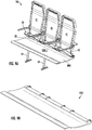
- Figs. 1-8 illustrate embodiments of variable section benches 101 for passenger seats 100 where the variable section bench 101 spans along the full length of the seat 100 in the lateral direction ( see Fig. 1 ) such that the seat 100 may include multiple seat backs 21,31, 41 and belts 22, 32, 42.
- the variable section bench 101 includes a seating surface 101.1 common to all seat backs and has a varying contour and thickness such that the variable section bench 101 is structurally optimized to withstand and transfer all seat loads into the frame assemblies of the seat 100 without the need for separate structural members along the length of the seat 100 ( see Fig. 1 ).
- the seating surface 101.1 may have cushions, layers of foam, or other appropriate objects (not shown) to mimic separation for the portions of the variable section bench 101 for multiple passengers.
- variable section bench 101 may be adapted for use with seats for any number of occupants, including as few as one or as many as ten or more occupants.
- the variable section bench 101 may include an upper layer 102, a middle layer 103, and a lower layer 104 ( see Fig. 8 ).
- the variable section bench 101 may include additional layers based on specific structural attachments for the variable section bench 101 and/or loading conditions.
- the variable section bench 101 may interface with at least one frame assembly, where each frame assembly may include a forward frame member 51, 52 and an aft frame member 61, 62.
- the forward frame member 51, 52 may extend through the variable section bench 101 and attach to an upper support platform 71, 72.
- the aft frame member 61 may include an upper portion 63 that includes a contoured surface 64 that corresponds to an appropriate portion of the underside of the variable section bench 101.
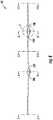
- Fig. 3 shows section 3-3 ( see Fig. 2 ), which is a section view looking in the lateral direction of the seat 100.
- Fasteners 11 may extend from the upper support platform 71, 72 through the variable section bench 101 into threaded holes in the upper portion 63 of the aft frame member 61, 62.
- Conventional seats typically require at least one structural member (in addition to the seat pan) extending along the length of the seat with attachment to the various frame assemblies (e.g., attaching to both (1) forward frame member 51/aft frame member 61 and (2) forward frame member 52/aft frame member 62).
- variable section bench 101 incorporate structural features and seat pan components into a single component to eliminate additional structural members extending along the length of the seat with attachment to the various frame assemblies.
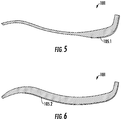
- the variable section bench 101 reduces thickness when moving away from the aft end (where the variable section bench 101 attaches to the seat backs and belts) toward the forward end of the variable section bench 101.
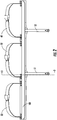
- the thickness of the variable section bench 101 may also change along the length as shown in Fig. 4.
- Fig. 4 is a section view of the entire variable section bench 101 looking aft.
- the variable section bench 101 may have a fore-aft section 5-5 ( see Figs.
- variable section bench 101 may also have an internal section 5.1-5.1 that is approximately halfway between the adjacent frame interface portions, a section 6.1-6.1 for interfacing with a second frame assembly (forward frame member 52 and aft frame member 62), and a section 5.2-5.2 at a cantilevered second end of the seat 100.
- a frame interface portion is fore-aft section 6-6 ( see Figs. 4 and 6 ) for interfacing with a first frame assembly (forward frame member 51 and aft frame member 61).
- the variable section bench 101 may also have an internal section 5.1-5.1 that is approximately halfway between the adjacent frame interface portions, a section 6.1-6.1 for interfacing with a second frame assembly (forward frame member 52 and aft frame member 62), and a section 5.2-5.2 at a cantilevered second end of the seat 100.
- section 5.1-5.1 and section 5.2-5.2 may be similar to section 5-5. However, this is not always the case.
- internal section 5.1-5.1 due to its proximity to the frame attachments at section 6-6 and section 6.1-6.1 may require less material to withstand bending loads and to properly distribute loads compared to at least one of section 5-5 and section 5.2-5.2.
- section 6.1-6.1 may be similar to section 6-6. However, this is not always the case.
- section 6.1-6.1 due to the shorter cantilevered distance of section 5.2-5.2) may require less material to withstand bending loads and to properly distribute loads compared to section 6-6.
- variable section bench 101 is designed to withstand high loads (e.g., shear and bending loads) in the areas near attachment of the frame assemblies.
- high loads e.g., shear and bending loads
- section 6-6 and section 6.1-6.1 may include increased thickness compared to other portions of the variable section bench 101. The increased thickness may be based on local plies of composite material (e.g., woven graphite), metallic features (e.g., machined or sheet metal), composite core material between upper and lower composite face plies, or other relevant features.
- variable section bench 101 may include a thickness reduction 106 on a first side of the interface with a frame at section 6-6 (i.e., with forward frame member 51 and aft frame member 61) and a thickness reduction 107 on a second side of the interface with a frame at section 6-6.
- the thickness reduction 106 on the first side of the frame interface may be symmetric relative to the thickness reduction 107 on the second side of the frame interface, although this is not always the case.
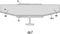
- the variable section bench 101 may include a thickness reduction 108 on a first side of the interface with a frame at section 6.1-6.1 (i.e., with forward frame member 52 and aft frame member 62) and a thickness reduction 109 on a second side of the interface with a frame at section 6.1-6.1.
- the thickness reduction 108 on the first side of the frame interface may be symmetric relative to the thickness reduction 109 on the second side of the frame interface, although this is not always the case.
- the thickness reductions 106-109 each correspond to a series of composite plies that terminate in a stair-step fashion and/or to core that ramps down to a reduced thickness.
- the overall thickness of the variable section bench 101 at section 5-5 may reduce quickly to a minimum thickness when moving away from the aft of the seat 100 ( i.e., near attachment to the seat backs 21, 31, 41). In some embodiments, the section 5-5 reaches a minimum thickness before reaching a halfway point between the aft end and the forward end of the variable section bench 101.
- the reinforcement layer 105 ( see Fig. 8 ) may include a first portion 105.1 at section 5-5 that stops near an aft end of the variable section bench 101.
- the first portion 105.1 extends along the entire length of the variable section bench 101 in the lateral direction and extends approximately 25% from the aft end of the variable section bench 101 (toward the forward end).
- Fig. 6 shows one example of a section 6-6 where the section does not reach a minimum thickness until approximately the forward end of the variable section bench 101.
- a second portion 105.2 of the reinforcement layer 105 may extend a greater distance from the aft end of the variable section bench 101 compared to the first portion 105.1.
- the second portion 105.2 extends approximately 75% from the aft end of the variable section bench 101.
- the reinforcement layer 105 may include a third portion 105.3 aligned with section 6.1-6.1 that is similar to second portion 105.2.
- the variable section bench 101 may include an upper layer 102, a middle layer 103, a lower layer 104, and a reinforcement layer 105.
- at least one of the upper layer 102 and the lower layer 104 have a constant thickness throughout a majority of the entire respective layer.
- the upper layer 102 and the lower layer 104 may each span the approximately entire surface area of the variable section bench 101.
- the middle layer 103 may also span the approximately entire surface area of the variable section bench 101.
- the upper layer 102 and/or the lower layer 104 may be a group of one or more woven and/or unidirectional graphite plies or any other suitable material.
- the middle layer 103 may include at least one woven and/or unidirectional graphite plies, core ( e.g., hard foam core, hex-cell core, crush core, etc. ), a combination thereof, or any other suitable material.
- the variable section bench 101 includes a sandwich panel construction.
- the middle layer 103 may have variable thickness in at least one direction (e.g., the thickness of the middle layer 103 may change when moving from the aft end of the seat toward the forward end and/or may change when moving along the length of the seat 100).
- the variation in thickness between different sections along the length of the variable section bench 101 is primarily due to the differences between the middle layer 103 in the respective areas.
- Figs. 5-8 illustrate the reinforcement layer 105 as disposed below the lower layer 104, in some embodiments, the reinforcement layer 105 is disposed between the middle layer 103 and the lower layer 104.
- Figs. 9A-12 illustrate embodiments of variable section benches 1001 for passenger seats 100
- the variable section bench 1001 includes a seating surface 1001.1 that extends along the full length of the seat 100 in the lateral direction such that the seat 100 may include multiple seat backs 21, 31, 41 and belts 22, 32, 42.
- the seating surface 1001.1 is common to all seat backs and may have cushions, layers of foam, or other appropriate objects (not shown) to mimic separation for the portions of the variable section bench 1001 for multiple passengers.
- the drawings focus on seats 100 that are configured for three occupants; however the variable section bench 1001 may be adapted for use with seats for any number of occupants, including as few as one or as many as ten or more occupants.
- variable section bench 1001 may include an upper layer 1002, a middle layer 1003, and a lower layer 1004 ( see Figs. 10-12 ). In some cases, the variable section bench 1001 may include additional layers based on specific structural attachments for the variable section bench 1001 and/or loading conditions.
- variable section bench 1001 may interface with at least one frame assembly (including a forward frame member 51, 52 and an aft frame member 61, 62) similar to the variable section bench 101.
- the variable section bench 1001 reduces thickness at the forward end of the variable section bench 1001 compared to the aft end (where the variable section bench 1001 attaches to the seat backs and belts).
- the thickness of the variable section bench 1001 may also change along the length as shown in Fig. 10.
- Fig. 10 is a section view of the entire variable section bench 1001 looking aft.
- the variable section bench 1001 may have a fore-aft section 11-11 ( see Figs.
- variable section bench 1001 may also have an internal section 11.1-11.1 that is approximately halfway between the adjacent frame interface portions, a section 12.1-12.1 for interfacing with a second frame assembly (forward frame member 52 and aft frame member 62), and a section 11.2-11.2 at a cantilevered second end of the seat 100.
- at least one of section 11.1-11.1 and section 11.2-11.2 may be similar to section 11-11.
- internal section 11.1-11.1 (due to its proximity to the frame attachments at section 12-12 and section 12.1-12.1) may require less material to withstand bending loads and to properly distribute loads compared to at least one of section 11-11 and section 11.2-11.2.
- section 12.1-12.1 may be similar to section 12-12. However, this is not always the case.
- variable section bench 1001 is designed to withstand high loads (e.g., shear and bending loads) in the areas near attachment of the frame assemblies.
- high loads e.g., shear and bending loads
- section 12-12 and section 12.1-12.1 may include increased thickness compared to other portions of the variable section bench 1001. The increased thickness may be based on local plies of composite material (e.g., woven graphite), metallic features (e.g., machined or sheet metal), composite core material between upper and lower composite face plies, or other relevant features.
- variable section bench 1001 may include a thickness reduction 1006 on a first side of the interface with a frame at section 12-12 ( i.e., with forward frame member 51 and aft frame member 61) and a thickness reduction 1007 on a second side of the interface with a frame at section 12-12. As shown in Fig.
- the thickness reduction 1006 on the first side of the frame interface may extend further from the interface with the frame at section 12-12 (and may reduce in thickness more gradually) than the thickness reduction 1007 on the second side of the frame interface.
- the additional material of thickness reduction 1006 may ensure the variable section bench 1001 can properly distribute loads adjacent to the cantilevered end (near section 11-11) while loads at internal section 11.1-11.1 can be distributed to the frame attachments at both section 12-12 and section 12.1-12.1.
- the thickness reduction 1006 on the first side of the frame interface may be symmetric relative to the thickness reduction 1007 on the second side of the frame interface.
- the variable section bench 1001 may include a thickness reduction 1008 on a first side of the interface with a frame at section 12.1-12.1 (i.e., with forward frame member 52 and aft frame member 62) and a thickness reduction 1009 on a second side of the interface with a frame at section 12.1-12.1.
- the thickness reduction 1008 on the first side of the frame interface may extend further from the interface with the frame at section 12.1-12.1 (and may reduce in thickness more gradually) than the thickness reduction 1009 on the second side of the frame interface.
- the additional material of thickness reduction 1008 may ensure the variable section bench 1001 can properly distribute loads adjacent to the cantilevered end (near section 11.2-11.2) while loads at internal section 11.1-11.1 can be distributed to the frame attachments at both section 12-12 and section 12.1-12.1.
- the thickness reduction 1008 on the first side of the frame interface may be symmetric relative to the thickness reduction 1009 on the second side of the frame interface.
- the thickness reductions 1006-1009 each correspond to a series of composite plies that terminate in a stair-step fashion and/or to core that ramps down to a reduced thickness.
- the overall thickness of the variable section bench 1001 at section 11-11 may reduce quickly to a minimum thickness when moving away from the aft of the seat 100 ( i.e., near attachment to the seat backs 21, 31, 41).
- the section 11-11 reaches a minimum thickness before reaching a halfway point between the aft end and the forward end of the variable section bench 1001.
- Fig. 12 shows one example of a section 12-12 where the section does not reach a minimum thickness until approximately the forward end of the variable section bench 1001.
- the minimum thickness of the variable section bench 1001 at section 11-11 is approximately 0.63 cm to 1.9 cm (0.25 in to 0.75 in) ( see Fig. 11 ).
- the minimum thickness of the variable section bench 1001 at section 11-11 is approximately 1.27 cm (0.5 in).
- the thickness of the variable section bench 1001 at the forward end of section 12-12 may be approximately equal to the minimum thickness of the variable section bench 1001 at section 11-11.
- the thickness at the aft end of the variable section bench 1001 at section 11-11 is approximately 1.9 cm to 3.17 cm (0.75 in to 1.25 in).
- the thickness at the aft end of the variable section bench 1001 at section 11-11 is approximately 2.54 cm (1 in).
- the thickness of the variable section bench 1001 at the aft end of section 12-12 may be approximately equal to the thickness of the variable section bench 1001 at the aft end of section 11-11.
- the maximum thickness of the variable section bench 1001 at section 12-12 or section 12.1-12.1 is approximately 3.17 cm to 6.35 cm (1.5 in to 2.5 in). ( see Fig. 10 ). In certain embodiments, the maximum thickness of the variable section bench 1001 at section 12-12 or section 12.1-12.1 is approximately 5.08 cm (2 in). Accordingly, as shown in a comparison of Figs. 11 and 12 , at a location approximately halfway between the forward end and the aft end, the variable section bench 1001 at section 12-12 is approximately four times the thickness of the variable section bench 1001 at section 11-11 5.08 cm vs 1.27 cm (2 in vs 0.5 in ).
- the variable section bench 1001 may include an upper layer 1002, a middle layer 1003, and a lower layer 1004.
- the variable section bench 1001 may include a reinforcement layer (similar to reinforcement layer 105).
- at least one of the upper layer 1002 and the lower layer 1004 have a constant thickness throughout a majority of the entire respective layer.
- the upper layer 1002 and the lower layer 1004 may each span the approximately entire surface area of the variable section bench 1001.
- the middle layer 103 in some embodiments, may also span the approximately entire surface area of the variable section bench 1001.
- the upper layer 1002 and/or the lower layer 1004 may be a group of one or more woven and/or unidirectional graphite plies or any other suitable material.
- the middle layer 1003 may include at least one woven and/or unidirectional graphite plies, core ( e.g., hard foam core, hex-cell core, crush core, etc. ), a combination thereof, or any other suitable material.
- the variable section bench 1001 includes a sandwich panel construction.
- the middle layer 1003 may have variable thickness in at least one direction (e.g., the thickness of the middle layer 1003 may change when moving from the aft end of the seat toward the forward end and/or may change when moving along the length of the seat 100).
- the variation in thickness between different sections along the length of the variable section bench 1001 e.g., differences between section 11-11 and section 12-12
- the components of the seat 100 may be formed of materials including, but not limited to, aluminum, steel, titanium, carbon composite, graphite composite, polyester, nylon, plastic, thermoplastic, other fabric materials, stainless steel, other plastic or polymer materials, other metallic materials, other composite materials, or other similar materials. Moreover, the components of the seat 100 may be attached to one another via suitable fasteners, which include, but are not limited to, screws, bolts, rivets or other mechanical or chemical fasteners.
Landscapes
- Engineering & Computer Science (AREA)
- Aviation & Aerospace Engineering (AREA)
- Transportation (AREA)
- Mechanical Engineering (AREA)
- Seats For Vehicles (AREA)
Description
- This application is related to and claims priority benefit from U. S. Provisional Application No.
62/482,341 - The field of the invention relates to benches with variable thicknesses in seats for aircraft or the like.
- Passenger seats, and particularly vehicle or aircraft passenger seats, are designed to ensure passenger safety for various loading conditions including, for example, hard landings and crash conditions. In some instances, regulatory and/or governmental requirements dictate that seats comply with occupant protection/impact tests. The seats must be capable of sustaining loads that cause floor deformation in the vehicle and/or significant inertial loads related to the mass of the occupant. Conventional seats (typically designed for two to four occupants) use a framework arrangement with a plurality of frames between occupants and a plurality of support members (cylindrical tubes) that extend laterally and connect to each of the plurality of frames. A seat pan is then attached to the framework (the frames and lateral support members). An example of such framework is described in
U.S. Application No. 15/314,123 (Pub. No.2017/0096226 ). Another example is shown in documentUS2009084925 . - In certain situations, it may be desirable to design seats and related subcomponents to minimize weight and maximize structural efficiency with load paths configured to transfer load from the passenger through the seat and into the structure of the aircraft. In particular, it may be desirable to design and produce a bench structure for a seat with varying sections designed specifically based on loading conditions for the seat where the seat incorporates integral lateral supports and thus eliminates the need for separate structural members in the seat framework for supporting lateral loads.
- The terms "invention," "the invention," "this invention" and "the present invention" used in this patent are intended to refer broadly to all of the subject matter of this patent and the patent claims below. Statements containing these terms should be understood not to limit the subject matter described herein or to limit the meaning or scope of the patent claims below. Embodiments of the invention covered by this patent are defined by the claims below, not this summary. This summary is a high-level overview of various aspects of the invention and introduces some of the concepts that are further described in the Detailed Description section below. This summary is not intended to identify key or essential features of the claimed subject matter, nor is it intended to be used in isolation to determine the scope of the claimed subject matter. The subject matter should be understood by reference to appropriate portions of the entire specification of this patent, any or all drawings and each claim.
- According to the present invention, a vehicle seat is disclosed in claim 1. Further details are disclosed in the dependent claims.
-
-
Fig. 1 is a perspective view of a passenger seat according to certain embodiments of the present invention. -
Fig. 2 is a front view of the passenger seat ofFig. 1 . -
Fig. 3 is a section view of the passenger seat ofFig. 2 . -
Fig. 4 is a section view of the passenger seat ofFig. 3 . -
Figs. 5 and 6 are section views of the passenger seat ofFig. 4 . -
Fig. 7 is a detail view of the section view of the passenger seat ofFig. 4 . -
Fig. 8 is an exploded view of the variable section bench of the passenger seat ofFig. 1 . -
Fig. 9A is a perspective view of a passenger seat according to certain embodiments of the present invention. -
Fig. 9B is a perspective view of the variable section bench of the passenger seat ofFig. 9A . -
Fig. 10 is a section view of the variable section bench ofFig. 9B . -
Figs. 11 and 12 are section views of the variable section bench ofFig. 10 . - The subject matter of embodiments of the present invention is described here with specificity to meet statutory requirements, but this description is not necessarily intended to limit the scope of the claims. The claimed subject matter may be embodied in other ways, may include different elements or steps, and may be used in conjunction with other existing or future technologies. This description should not be interpreted as implying any particular order or arrangement among or between various steps or elements except when the order of individual steps or arrangement of elements is explicitly described.
-
Figs. 1-8 illustrate embodiments ofvariable section benches 101 forpassenger seats 100 where thevariable section bench 101 spans along the full length of theseat 100 in the lateral direction (seeFig. 1 ) such that theseat 100 may includemultiple seat backs belts variable section bench 101 includes a seating surface 101.1 common to all seat backs and has a varying contour and thickness such that thevariable section bench 101 is structurally optimized to withstand and transfer all seat loads into the frame assemblies of theseat 100 without the need for separate structural members along the length of the seat 100 (seeFig. 1 ). The seating surface 101.1 may have cushions, layers of foam, or other appropriate objects (not shown) to mimic separation for the portions of thevariable section bench 101 for multiple passengers. The drawings focus onseats 100 that are configured for three occupants; however thevariable section bench 101 may be adapted for use with seats for any number of occupants, including as few as one or as many as ten or more occupants. In these embodiments, thevariable section bench 101 may include anupper layer 102, amiddle layer 103, and a lower layer 104 (seeFig. 8 ). In some cases, thevariable section bench 101 may include additional layers based on specific structural attachments for thevariable section bench 101 and/or loading conditions. - In some embodiments, as shown in
Figs. 1-3 , thevariable section bench 101 may interface with at least one frame assembly, where each frame assembly may include aforward frame member aft frame member forward frame member variable section bench 101 and attach to anupper support platform Fig. 3 , theaft frame member 61 may include anupper portion 63 that includes acontoured surface 64 that corresponds to an appropriate portion of the underside of thevariable section bench 101.Fig. 3 shows section 3-3 (seeFig. 2 ), which is a section view looking in the lateral direction of theseat 100.Fasteners 11 may extend from theupper support platform variable section bench 101 into threaded holes in theupper portion 63 of theaft frame member forward frame member 51/aft frame member 61 and (2)forward frame member 52/aft frame member 62). However, variable section bench 101 (andvariable section bench 1001 described below) incorporate structural features and seat pan components into a single component to eliminate additional structural members extending along the length of the seat with attachment to the various frame assemblies. - As shown in
Figs. 5 and 6 , thevariable section bench 101 reduces thickness when moving away from the aft end (where thevariable section bench 101 attaches to the seat backs and belts) toward the forward end of thevariable section bench 101. In addition to changing thicknesses of thevariable section bench 101 when moving from the aft end of thevariable section bench 101 to the forward end of the variable section bench 101 (seeFigs. 3 ,5, 6 ), the thickness of thevariable section bench 101 may also change along the length as shown inFig. 4. Fig. 4 is a section view of the entirevariable section bench 101 looking aft. For example, thevariable section bench 101 may have a fore-aft section 5-5 (seeFigs. 4 and5 ) at or near a cantilevered first end and at least one frame interface portion. One example of a frame interface portion is fore-aft section 6-6 (seeFigs. 4 and6 ) for interfacing with a first frame assembly (forward frame member 51 and aft frame member 61). Thevariable section bench 101 may also have an internal section 5.1-5.1 that is approximately halfway between the adjacent frame interface portions, a section 6.1-6.1 for interfacing with a second frame assembly (forward frame member 52 and aft frame member 62), and a section 5.2-5.2 at a cantilevered second end of theseat 100. In some embodiments, as shown inFig. 4 , at least one of section 5.1-5.1 and section 5.2-5.2 may be similar to section 5-5. However, this is not always the case. For example, in some embodiments, internal section 5.1-5.1 (due to its proximity to the frame attachments at section 6-6 and section 6.1-6.1) may require less material to withstand bending loads and to properly distribute loads compared to at least one of section 5-5 and section 5.2-5.2. Furthermore, there may be different requirements for the flexibility of thevariable section bench 101 near the ends (section 5-5 and section 5.2-5.2) compared to between the frame attachments (internal section 5.1-5.1). In addition, in certain embodiments, as shown inFig. 4 , section 6.1-6.1 may be similar to section 6-6. However, this is not always the case. For example, in some embodiments, section 6.1-6.1 (due to the shorter cantilevered distance of section 5.2-5.2) may require less material to withstand bending loads and to properly distribute loads compared to section 6-6. - Because the seat loads (e.g., loads related to occupants sitting on the variable section bench 101) must transfer from the
variable section bench 101 into the structure of the vehicle, thevariable section bench 101 is designed to withstand high loads (e.g., shear and bending loads) in the areas near attachment of the frame assemblies. For example, section 6-6 and section 6.1-6.1 may include increased thickness compared to other portions of thevariable section bench 101. The increased thickness may be based on local plies of composite material (e.g., woven graphite), metallic features (e.g., machined or sheet metal), composite core material between upper and lower composite face plies, or other relevant features. The increased thickness in these areas may increase the capability of thevariable section bench 101 to withstand bearing loads, may facilitate attachment to the frame member(s), may increase the moment of inertia properties (thus affecting bending capability), or may produce any other relevant effect. As shown inFig. 4 , thevariable section bench 101 may include athickness reduction 106 on a first side of the interface with a frame at section 6-6 (i.e., withforward frame member 51 and aft frame member 61) and athickness reduction 107 on a second side of the interface with a frame at section 6-6. Thethickness reduction 106 on the first side of the frame interface may be symmetric relative to thethickness reduction 107 on the second side of the frame interface, although this is not always the case. Similarly, as shown inFigs. 4 and7 , thevariable section bench 101 may include athickness reduction 108 on a first side of the interface with a frame at section 6.1-6.1 (i.e., withforward frame member 52 and aft frame member 62) and athickness reduction 109 on a second side of the interface with a frame at section 6.1-6.1. Thethickness reduction 108 on the first side of the frame interface may be symmetric relative to thethickness reduction 109 on the second side of the frame interface, although this is not always the case. In some embodiments, the thickness reductions 106-109 each correspond to a series of composite plies that terminate in a stair-step fashion and/or to core that ramps down to a reduced thickness. - As shown in
Fig. 5 , in some embodiments, the overall thickness of thevariable section bench 101 at section 5-5 may reduce quickly to a minimum thickness when moving away from the aft of the seat 100 (i.e., near attachment to the seat backs 21, 31, 41). In some embodiments, the section 5-5 reaches a minimum thickness before reaching a halfway point between the aft end and the forward end of thevariable section bench 101. The reinforcement layer 105 (seeFig. 8 ) may include a first portion 105.1 at section 5-5 that stops near an aft end of thevariable section bench 101. In some embodiments, the first portion 105.1 extends along the entire length of thevariable section bench 101 in the lateral direction and extends approximately 25% from the aft end of the variable section bench 101 (toward the forward end).Fig. 6 shows one example of a section 6-6 where the section does not reach a minimum thickness until approximately the forward end of thevariable section bench 101. A second portion 105.2 of the reinforcement layer 105 (seeFig. 8 ) may extend a greater distance from the aft end of thevariable section bench 101 compared to the first portion 105.1. In some embodiments, the second portion 105.2 extends approximately 75% from the aft end of thevariable section bench 101. As shown inFigs. 7 and8 , thereinforcement layer 105 may include a third portion 105.3 aligned with section 6.1-6.1 that is similar to second portion 105.2. - As shown in
Fig. 8 , in some embodiments, thevariable section bench 101 may include anupper layer 102, amiddle layer 103, alower layer 104, and areinforcement layer 105. In some examples, at least one of theupper layer 102 and thelower layer 104 have a constant thickness throughout a majority of the entire respective layer. Theupper layer 102 and thelower layer 104 may each span the approximately entire surface area of thevariable section bench 101. As shown inFig. 8 , themiddle layer 103 may also span the approximately entire surface area of thevariable section bench 101. Theupper layer 102 and/or thelower layer 104 may be a group of one or more woven and/or unidirectional graphite plies or any other suitable material. Themiddle layer 103 may include at least one woven and/or unidirectional graphite plies, core (e.g., hard foam core, hex-cell core, crush core, etc.), a combination thereof, or any other suitable material. In some embodiments, thevariable section bench 101 includes a sandwich panel construction. Themiddle layer 103 may have variable thickness in at least one direction (e.g., the thickness of themiddle layer 103 may change when moving from the aft end of the seat toward the forward end and/or may change when moving along the length of the seat 100). In some embodiments, the variation in thickness between different sections along the length of the variable section bench 101 (e.g., differences between section 5-5 and section 6-6) is primarily due to the differences between themiddle layer 103 in the respective areas. AlthoughFigs. 5-8 illustrate thereinforcement layer 105 as disposed below thelower layer 104, in some embodiments, thereinforcement layer 105 is disposed between themiddle layer 103 and thelower layer 104. -
Figs. 9A-12 illustrate embodiments ofvariable section benches 1001 forpassenger seats 100 where thevariable section bench 1001 includes a seating surface 1001.1 that extends along the full length of theseat 100 in the lateral direction such that theseat 100 may include multiple seat backs 21, 31, 41 andbelts variable section bench 1001 for multiple passengers. The drawings focus onseats 100 that are configured for three occupants; however thevariable section bench 1001 may be adapted for use with seats for any number of occupants, including as few as one or as many as ten or more occupants. In these embodiments, thevariable section bench 1001 may include anupper layer 1002, amiddle layer 1003, and a lower layer 1004 (seeFigs. 10-12 ). In some cases, thevariable section bench 1001 may include additional layers based on specific structural attachments for thevariable section bench 1001 and/or loading conditions. - In some embodiments, the
variable section bench 1001 may interface with at least one frame assembly (including aforward frame member aft frame member 61, 62) similar to thevariable section bench 101. - As shown in
Figs. 11 and 12 , thevariable section bench 1001 reduces thickness at the forward end of thevariable section bench 1001 compared to the aft end (where thevariable section bench 1001 attaches to the seat backs and belts). In addition to changing thicknesses of thevariable section bench 101 when moving from the aft end of thevariable section bench 1001 to the forward end of the variable section bench 1001 (seeFigs. 11 and 12 ), the thickness of thevariable section bench 1001 may also change along the length as shown inFig. 10. Fig. 10 is a section view of the entirevariable section bench 1001 looking aft. Thevariable section bench 1001 may have a fore-aft section 11-11 (seeFigs. 10 and11 ) at or near a cantilevered first end and at least one frame interface portion. One example of a frame interface portion is fore-aft section 12-12 (seeFigs. 10 and12 ) for interfacing with a first frame assembly (forward frame member 51 and aft frame member 61). Thevariable section bench 1001 may also have an internal section 11.1-11.1 that is approximately halfway between the adjacent frame interface portions, a section 12.1-12.1 for interfacing with a second frame assembly (forward frame member 52 and aft frame member 62), and a section 11.2-11.2 at a cantilevered second end of theseat 100. In some embodiments, as shown inFig. 10 , at least one of section 11.1-11.1 and section 11.2-11.2 may be similar to section 11-11. However, this is not always the case. For example, in some embodiments, internal section 11.1-11.1 (due to its proximity to the frame attachments at section 12-12 and section 12.1-12.1) may require less material to withstand bending loads and to properly distribute loads compared to at least one of section 11-11 and section 11.2-11.2. Furthermore, there may be different requirements for the flexibility of thevariable section bench 1001 near the ends (section 11-11 and section 11.2-11.2) compared to between the frame attachments (internal section 11.1-11.1). In addition, in certain embodiments, as shown inFig. 10 , section 12.1-12.1 may be similar to section 12-12. However, this is not always the case. - Because the seat loads (e.g., loads related to occupants sitting on the variable section bench 1001) must transfer from the
variable section bench 1001 into the structure of the vehicle, thevariable section bench 1001 is designed to withstand high loads (e.g., shear and bending loads) in the areas near attachment of the frame assemblies. For example, section 12-12 and section 12.1-12.1 may include increased thickness compared to other portions of thevariable section bench 1001. The increased thickness may be based on local plies of composite material (e.g., woven graphite), metallic features (e.g., machined or sheet metal), composite core material between upper and lower composite face plies, or other relevant features. The increased thickness in these areas may increase the capability of thevariable section bench 1001 to withstand bearing loads, may facilitate attachment to the frame member(s), may increase the moment of inertia properties (thus affecting bending capability), or may produce any other relevant effect. As shown inFig. 10 , thevariable section bench 1001 may include athickness reduction 1006 on a first side of the interface with a frame at section 12-12 (i.e., withforward frame member 51 and aft frame member 61) and athickness reduction 1007 on a second side of the interface with a frame at section 12-12. As shown inFig. 10 , thethickness reduction 1006 on the first side of the frame interface may extend further from the interface with the frame at section 12-12 (and may reduce in thickness more gradually) than thethickness reduction 1007 on the second side of the frame interface. The additional material of thickness reduction 1006 (compared to thickness reduction 1007) may ensure thevariable section bench 1001 can properly distribute loads adjacent to the cantilevered end (near section 11-11) while loads at internal section 11.1-11.1 can be distributed to the frame attachments at both section 12-12 and section 12.1-12.1. Although not illustrated, thethickness reduction 1006 on the first side of the frame interface may be symmetric relative to thethickness reduction 1007 on the second side of the frame interface. - As shown in
Fig. 10 , thevariable section bench 1001 may include athickness reduction 1008 on a first side of the interface with a frame at section 12.1-12.1 (i.e., withforward frame member 52 and aft frame member 62) and athickness reduction 1009 on a second side of the interface with a frame at section 12.1-12.1. As shown inFig. 10 , thethickness reduction 1008 on the first side of the frame interface may extend further from the interface with the frame at section 12.1-12.1 (and may reduce in thickness more gradually) than thethickness reduction 1009 on the second side of the frame interface. The additional material of thickness reduction 1008 (compared to thickness reduction 1009) may ensure thevariable section bench 1001 can properly distribute loads adjacent to the cantilevered end (near section 11.2-11.2) while loads at internal section 11.1-11.1 can be distributed to the frame attachments at both section 12-12 and section 12.1-12.1. Although not illustrated, thethickness reduction 1008 on the first side of the frame interface may be symmetric relative to thethickness reduction 1009 on the second side of the frame interface. In some embodiments, the thickness reductions 1006-1009 each correspond to a series of composite plies that terminate in a stair-step fashion and/or to core that ramps down to a reduced thickness. - As shown in
Fig. 11 , in some embodiments, the overall thickness of thevariable section bench 1001 at section 11-11 may reduce quickly to a minimum thickness when moving away from the aft of the seat 100 (i.e., near attachment to the seat backs 21, 31, 41). In some embodiments, the section 11-11 reaches a minimum thickness before reaching a halfway point between the aft end and the forward end of thevariable section bench 1001.Fig. 12 shows one example of a section 12-12 where the section does not reach a minimum thickness until approximately the forward end of thevariable section bench 1001. In some embodiments, the minimum thickness of thevariable section bench 1001 at section 11-11 is approximately 0.63 cm to 1.9 cm (0.25 in to 0.75 in) (seeFig. 11 ). In certain embodiments, the minimum thickness of thevariable section bench 1001 at section 11-11 is approximately 1.27 cm (0.5 in). The thickness of thevariable section bench 1001 at the forward end of section 12-12 may be approximately equal to the minimum thickness of thevariable section bench 1001 at section 11-11. In some embodiments, the thickness at the aft end of thevariable section bench 1001 at section 11-11 is approximately 1.9 cm to 3.17 cm (0.75 in to 1.25 in). In some embodiments, the thickness at the aft end of thevariable section bench 1001 at section 11-11 is approximately 2.54 cm (1 in). The thickness of thevariable section bench 1001 at the aft end of section 12-12 may be approximately equal to the thickness of thevariable section bench 1001 at the aft end of section 11-11. In some embodiments, the maximum thickness of thevariable section bench 1001 at section 12-12 or section 12.1-12.1 is approximately 3.17 cm to 6.35 cm (1.5 in to 2.5 in). (seeFig. 10 ). In certain embodiments, the maximum thickness of thevariable section bench 1001 at section 12-12 or section 12.1-12.1 is approximately 5.08 cm (2 in). Accordingly, as shown in a comparison ofFigs. 11 and 12 , at a location approximately halfway between the forward end and the aft end, thevariable section bench 1001 at section 12-12 is approximately four times the thickness of thevariable section bench 1001 at section 11-11 5.08 cm vs 1.27 cm (2 in vs 0.5 in). - As shown in
Figs. 10-12 , in some embodiments, thevariable section bench 1001 may include anupper layer 1002, amiddle layer 1003, and alower layer 1004. Although not shown, thevariable section bench 1001 may include a reinforcement layer (similar to reinforcement layer 105). In some examples, at least one of theupper layer 1002 and thelower layer 1004 have a constant thickness throughout a majority of the entire respective layer. Theupper layer 1002 and thelower layer 1004 may each span the approximately entire surface area of thevariable section bench 1001. Themiddle layer 103, in some embodiments, may also span the approximately entire surface area of thevariable section bench 1001. Theupper layer 1002 and/or thelower layer 1004 may be a group of one or more woven and/or unidirectional graphite plies or any other suitable material. Themiddle layer 1003 may include at least one woven and/or unidirectional graphite plies, core (e.g., hard foam core, hex-cell core, crush core, etc.), a combination thereof, or any other suitable material. In some embodiments, thevariable section bench 1001 includes a sandwich panel construction. Themiddle layer 1003 may have variable thickness in at least one direction (e.g., the thickness of themiddle layer 1003 may change when moving from the aft end of the seat toward the forward end and/or may change when moving along the length of the seat 100). In some embodiments, the variation in thickness between different sections along the length of the variable section bench 1001 (e.g., differences between section 11-11 and section 12-12) is primarily due to the differences between themiddle layer 1003 in the respective areas. - The components of the
seat 100 may be formed of materials including, but not limited to, aluminum, steel, titanium, carbon composite, graphite composite, polyester, nylon, plastic, thermoplastic, other fabric materials, stainless steel, other plastic or polymer materials, other metallic materials, other composite materials, or other similar materials. Moreover, the components of theseat 100 may be attached to one another via suitable fasteners, which include, but are not limited to, screws, bolts, rivets or other mechanical or chemical fasteners. - Different arrangements of the components depicted in the drawings or described above, as well as components and steps not shown or described are possible. Similarly, some features and sub-combinations are useful and may be employed without reference to other features and sub-combinations. Embodiments of the invention have been described for illustrative and not restrictive purposes, and alternative embodiments will become apparent to readers of this patent. Accordingly, the present invention is not limited to the embodiments described above or depicted in the drawings, and various embodiments and modifications may be made without departing from the scope of the claims below.
Claims (10)
- A vehicle seat (100) comprising a variable thickness bench (101) for the vehicle seat (100), the variable thickness bench (101) comprising:an upper layer (102), a middle layer (103), and a lower layer (104);at least one frame interface portion comprising a fore-aft section (6-6 ; 6.1-6.1);at least one cantilevered portion at an end of the variable thickness bench (101) comprising a fore-aft section (5-5 ; 5.2-5.2); anda seating surface (101.1) that extends along a full length of the vehicle seat (100) in a lateral direction for a plurality of passengers, whereinthe at least one frame interface portion (6-6 ; 6.1-6.1) of the variable thickness bench (101) comprises increased thickness compared to the at least one cantilevered portion (5-5 ; 5.2-5.2),characterised in that the at least one frame interface portion (6-6 ; 6.1-6.1) comprises two frame interface portions (6-6 ; 6.1-6.1) and the variable thickness bench (101) comprises an internal fore-aft section (5.1-5.1) located approximately halfway between the two frame interface portions (6-6 ; 6.1-6.1), andin that, at a location of at least one of the two frame interface portions (6-6 ; 6.1-6.1), a thickness of the variable thickness bench (101) comprises a first reduction (107, 109) when moving toward the internal fore-aft section (5.1-5.1) and a second reduction (106, 108) when moving away from the internal fore-aft section (5.1-5.1).
- The vehicle seat of claim 1, characterized in that the at least one frame interface portion (6-6 ; 6.1-6.1) of the variable thickness bench (101) is approximately four times as thick as the at least one cantilevered portion (5-5 ; 5.2-5.2).
- The vehicle seat of claim 1, characterized in that the first and second reductions (106, 107, 108, 109) are symmetric about the location of at least one of the two frame interface portions (6-6 ; 6.1-6.1).
- The vehicle seat of claim 1, characterized in that the second reduction (106, 108) comprises a more gradual decrease in thickness compared to the first reduction (107, 109) such that the first and second reductions (106, 107, 108, 109) are asymmetric about the location of at least one of the two frame interface portions (6-6 ; 6.1-6.1).
- The vehicle seat of claim 1, characterized in that the upper (102) and lower (104) layers each comprise multiple plies of woven composite material.
- The vehicle seat of claim 1, characterized in that the middle layer (103) comprises at least one of woven composite material and composite foam core.
- The vehicle seat of claim 1, characterized in that it further comprises a reinforcement layer (105).
- The vehicle seat of claim 7, characterized in that the reinforcement layer (105) comprises a first portion (105.1) that extends along the full length of the vehicle seat (100) in the lateral direction and extends approximately 25% from an aft end of the variable thickness bench (101) toward a forward end of the variable thickness bench (101).
- The vehicle seat of claim 7, characterized in that the reinforcement layer (105) comprises a second portion (105.2) that is aligned with the at least one frame interface portion and extends approximately 75% from an aft end of the variable thickness bench (101) toward a forward end of the variable thickness bench (101).
- The vehicle seat of claim 1, characterized in that, at a location of the at least one frame interface portion, a frame member (51, 52, 61, 62) is disposed at a bottom surface of the variable thickness bench (101) and an upper support platform (71, 72) is disposed at a top surface of the variable thickness bench (101) such that a plurality of fasteners (11) extend from the upper support platform (71, 72) to the frame member (51, 52, 61, 62) through a full thickness of the variable thickness bench (101).
Applications Claiming Priority (2)
| Application Number | Priority Date | Filing Date | Title |
|---|---|---|---|
| US201762482341P | 2017-04-06 | 2017-04-06 | |
| PCT/US2017/052211 WO2018186905A1 (en) | 2017-04-06 | 2017-09-19 | Variable section bench for seat |
Publications (2)
| Publication Number | Publication Date |
|---|---|
| EP3606821A1 EP3606821A1 (en) | 2020-02-12 |
| EP3606821B1 true EP3606821B1 (en) | 2021-03-17 |
Family
ID=59974889
Family Applications (1)
| Application Number | Title | Priority Date | Filing Date |
|---|---|---|---|
| EP17777144.1A Active EP3606821B1 (en) | 2017-04-06 | 2017-09-19 | A vehicle seat |
Country Status (4)
| Country | Link |
|---|---|
| US (1) | US11117502B2 (en) |
| EP (1) | EP3606821B1 (en) |
| CN (1) | CN110636970B (en) |
| WO (1) | WO2018186905A1 (en) |
Families Citing this family (1)
| Publication number | Priority date | Publication date | Assignee | Title |
|---|---|---|---|---|
| US11117502B2 (en) * | 2017-04-06 | 2021-09-14 | Safran Seats Usa Llc | Variable section bench for seat |
Family Cites Families (26)
| Publication number | Priority date | Publication date | Assignee | Title |
|---|---|---|---|---|
| US4526421A (en) * | 1982-09-30 | 1985-07-02 | Ptc Aerospace Inc. | Multi-passenger aircraft seat having composite panel frame |
| GB8331260D0 (en) * | 1983-11-23 | 1983-12-29 | Toll I C | Aircraft seats |
| EP0197167B1 (en) * | 1985-04-04 | 1988-10-26 | Ignaz Vogel GmbH & Co KG, Fahrzeugsitze | Double passenger seat |
| US5284379A (en) * | 1991-09-04 | 1994-02-08 | The Boeing Company | Convertible aircraft passenger seats |
| DE19534025C1 (en) * | 1995-09-14 | 1996-11-28 | Daimler Benz Aerospace Airbus | Service unit for aircraft passengers |
| FR2774644B1 (en) * | 1998-02-12 | 2003-12-05 | Gec Alsthom Transport Sa | FIRST-SECOND CLASS MODULAR TWO-SEAT BENCH AND PROCESS FOR CONVERTING SUCH A BENCH |
| US7954762B2 (en) * | 2006-05-17 | 2011-06-07 | The Boeing Company | Lightweight aircraft passenger seat with composite construction |
| US7493844B2 (en) * | 2006-07-27 | 2009-02-24 | Chad Brian Martin | Vehicle security partition |
| US8393574B2 (en) * | 2006-12-22 | 2013-03-12 | The Boeing Company | Composite leg structure for a lightweight aircraft seat assembly |
| US7716797B2 (en) * | 2006-12-22 | 2010-05-18 | The Boeing Company | Composite seat pan structure for a lightweight aircraft seat assembly |
| US7717519B2 (en) * | 2006-12-22 | 2010-05-18 | The Boeing Company | Composite seat back structure for a lightweight aircraft seat assembly |
| US8205833B2 (en) * | 2006-12-22 | 2012-06-26 | The Boeing Company | Composite leg structure for a lightweight aircraft seat assembly |
| US7891033B2 (en) * | 2008-03-04 | 2011-02-22 | Invacare Corporation | Adjustable seat cushion assembly |
| WO2011014506A1 (en) * | 2009-07-27 | 2011-02-03 | Johnson Controls Technology Company | One-piece seat structures and method of forming |
| US8550564B1 (en) * | 2010-04-01 | 2013-10-08 | The Boeing Company | Composite seat pan structure for a lightweight aircraft seat assembly |
| US20130257132A1 (en) * | 2012-03-28 | 2013-10-03 | Fu-Chieng Chen | Seat Cushion |
| JP6017952B2 (en) * | 2012-12-27 | 2016-11-02 | トヨタ紡織株式会社 | Vehicle seat |
| US9480339B2 (en) * | 2012-12-31 | 2016-11-01 | Sava Cvek | Seat with pelvic support |
| WO2014163581A1 (en) * | 2013-04-05 | 2014-10-09 | Singapore Technologies Aerospace Ltd | Seat structure for a passenger seat and passenger seat |
| US9630717B2 (en) * | 2013-04-26 | 2017-04-25 | Encore Interiors, Inc. | Aircraft seating assembly with reduced spacing |
| DE102014200756A1 (en) * | 2014-01-17 | 2015-07-23 | Robert Bosch Gmbh | Gas injector for direct injection of gaseous fuel into a combustion chamber |
| US10124899B2 (en) | 2014-06-03 | 2018-11-13 | Zodiac Seats Us Llc | Hybrid composite structural member |
| US9764844B2 (en) * | 2015-04-13 | 2017-09-19 | Encore Seats, Inc. | Aircraft seating assembly |
| US10252804B2 (en) * | 2015-05-19 | 2019-04-09 | The Boeing Company | Galley refrigeration system of an aircraft |
| WO2017155566A1 (en) * | 2016-03-10 | 2017-09-14 | Zodiac Seats Us Llc | Aircraft seat back with non-tubular perimeter flange |
| US11117502B2 (en) * | 2017-04-06 | 2021-09-14 | Safran Seats Usa Llc | Variable section bench for seat |
-
2017
- 2017-09-19 US US16/603,027 patent/US11117502B2/en active Active
- 2017-09-19 WO PCT/US2017/052211 patent/WO2018186905A1/en not_active Ceased
- 2017-09-19 CN CN201780090773.5A patent/CN110636970B/en active Active
- 2017-09-19 EP EP17777144.1A patent/EP3606821B1/en active Active
Non-Patent Citations (1)
| Title |
|---|
| None * |
Also Published As
| Publication number | Publication date |
|---|---|
| CN110636970A (en) | 2019-12-31 |
| US11117502B2 (en) | 2021-09-14 |
| US20200189431A1 (en) | 2020-06-18 |
| EP3606821A1 (en) | 2020-02-12 |
| WO2018186905A1 (en) | 2018-10-11 |
| CN110636970B (en) | 2023-09-05 |
Similar Documents
| Publication | Publication Date | Title |
|---|---|---|
| EP3186150B1 (en) | Seat support system | |
| EP2550200B1 (en) | Passenger seat assembly with associated floor panel and aircraft sidewall attachment, and method | |
| EP3152114B1 (en) | Hybrid composite structural member | |
| US11040775B2 (en) | Seat assemblies, such as for use in aircraft, and associated systems and methods | |
| US8226163B1 (en) | Aircraft divan | |
| EP3694778B1 (en) | Two-piece center frame assembly | |
| EP3129290B1 (en) | Seat unit limiting the risk of head injuries | |
| EP4200213B1 (en) | Structural assembly for passenger seat and associated methods | |
| EP2769916A2 (en) | Aircraft seat energy absorbing device for occupant restraint | |
| US7399037B2 (en) | Double-spar chassis for aircraft passenger seat | |
| EP3606821B1 (en) | A vehicle seat | |
| EP1793704A1 (en) | Flexible seat frame | |
| EP3976473B1 (en) | Frame component with variable wall thickness | |
| EP3326860B1 (en) | Energy absorbing assembly for a seat | |
| EP4328134A1 (en) | Baggage bar energy absorber |
Legal Events
| Date | Code | Title | Description |
|---|---|---|---|
| STAA | Information on the status of an ep patent application or granted ep patent |
Free format text: STATUS: UNKNOWN |
|
| STAA | Information on the status of an ep patent application or granted ep patent |
Free format text: STATUS: THE INTERNATIONAL PUBLICATION HAS BEEN MADE |
|
| PUAI | Public reference made under article 153(3) epc to a published international application that has entered the european phase |
Free format text: ORIGINAL CODE: 0009012 |
|
| STAA | Information on the status of an ep patent application or granted ep patent |
Free format text: STATUS: REQUEST FOR EXAMINATION WAS MADE |
|
| 17P | Request for examination filed |
Effective date: 20191003 |
|
| AK | Designated contracting states |
Kind code of ref document: A1 Designated state(s): AL AT BE BG CH CY CZ DE DK EE ES FI FR GB GR HR HU IE IS IT LI LT LU LV MC MK MT NL NO PL PT RO RS SE SI SK SM TR |
|
| AX | Request for extension of the european patent |
Extension state: BA ME |
|
| DAV | Request for validation of the european patent (deleted) | ||
| DAX | Request for extension of the european patent (deleted) | ||
| GRAP | Despatch of communication of intention to grant a patent |
Free format text: ORIGINAL CODE: EPIDOSNIGR1 |
|
| STAA | Information on the status of an ep patent application or granted ep patent |
Free format text: STATUS: GRANT OF PATENT IS INTENDED |
|
| INTG | Intention to grant announced |
Effective date: 20201007 |
|
| GRAS | Grant fee paid |
Free format text: ORIGINAL CODE: EPIDOSNIGR3 |
|
| GRAA | (expected) grant |
Free format text: ORIGINAL CODE: 0009210 |
|
| STAA | Information on the status of an ep patent application or granted ep patent |
Free format text: STATUS: THE PATENT HAS BEEN GRANTED |
|
| AK | Designated contracting states |
Kind code of ref document: B1 Designated state(s): AL AT BE BG CH CY CZ DE DK EE ES FI FR GB GR HR HU IE IS IT LI LT LU LV MC MK MT NL NO PL PT RO RS SE SI SK SM TR |
|
| REG | Reference to a national code |
Ref country code: GB Ref legal event code: FG4D |
|
| REG | Reference to a national code |
Ref country code: CH Ref legal event code: EP |
|
| REG | Reference to a national code |
Ref country code: DE Ref legal event code: R096 Ref document number: 602017034831 Country of ref document: DE |
|
| REG | Reference to a national code |
Ref country code: IE Ref legal event code: FG4D |
|
| REG | Reference to a national code |
Ref country code: AT Ref legal event code: REF Ref document number: 1372019 Country of ref document: AT Kind code of ref document: T Effective date: 20210415 |
|
| REG | Reference to a national code |
Ref country code: LT Ref legal event code: MG9D |
|
| PG25 | Lapsed in a contracting state [announced via postgrant information from national office to epo] |
Ref country code: GR Free format text: LAPSE BECAUSE OF FAILURE TO SUBMIT A TRANSLATION OF THE DESCRIPTION OR TO PAY THE FEE WITHIN THE PRESCRIBED TIME-LIMIT Effective date: 20210618 Ref country code: FI Free format text: LAPSE BECAUSE OF FAILURE TO SUBMIT A TRANSLATION OF THE DESCRIPTION OR TO PAY THE FEE WITHIN THE PRESCRIBED TIME-LIMIT Effective date: 20210317 Ref country code: HR Free format text: LAPSE BECAUSE OF FAILURE TO SUBMIT A TRANSLATION OF THE DESCRIPTION OR TO PAY THE FEE WITHIN THE PRESCRIBED TIME-LIMIT Effective date: 20210317 Ref country code: NO Free format text: LAPSE BECAUSE OF FAILURE TO SUBMIT A TRANSLATION OF THE DESCRIPTION OR TO PAY THE FEE WITHIN THE PRESCRIBED TIME-LIMIT Effective date: 20210617 Ref country code: BG Free format text: LAPSE BECAUSE OF FAILURE TO SUBMIT A TRANSLATION OF THE DESCRIPTION OR TO PAY THE FEE WITHIN THE PRESCRIBED TIME-LIMIT Effective date: 20210617 |
|
| REG | Reference to a national code |
Ref country code: AT Ref legal event code: MK05 Ref document number: 1372019 Country of ref document: AT Kind code of ref document: T Effective date: 20210317 |
|
| REG | Reference to a national code |
Ref country code: NL Ref legal event code: MP Effective date: 20210317 |
|
| PG25 | Lapsed in a contracting state [announced via postgrant information from national office to epo] |
Ref country code: RS Free format text: LAPSE BECAUSE OF FAILURE TO SUBMIT A TRANSLATION OF THE DESCRIPTION OR TO PAY THE FEE WITHIN THE PRESCRIBED TIME-LIMIT Effective date: 20210317 Ref country code: LV Free format text: LAPSE BECAUSE OF FAILURE TO SUBMIT A TRANSLATION OF THE DESCRIPTION OR TO PAY THE FEE WITHIN THE PRESCRIBED TIME-LIMIT Effective date: 20210317 Ref country code: SE Free format text: LAPSE BECAUSE OF FAILURE TO SUBMIT A TRANSLATION OF THE DESCRIPTION OR TO PAY THE FEE WITHIN THE PRESCRIBED TIME-LIMIT Effective date: 20210317 |
|
| PG25 | Lapsed in a contracting state [announced via postgrant information from national office to epo] |
Ref country code: NL Free format text: LAPSE BECAUSE OF FAILURE TO SUBMIT A TRANSLATION OF THE DESCRIPTION OR TO PAY THE FEE WITHIN THE PRESCRIBED TIME-LIMIT Effective date: 20210317 |
|
| PG25 | Lapsed in a contracting state [announced via postgrant information from national office to epo] |
Ref country code: AT Free format text: LAPSE BECAUSE OF FAILURE TO SUBMIT A TRANSLATION OF THE DESCRIPTION OR TO PAY THE FEE WITHIN THE PRESCRIBED TIME-LIMIT Effective date: 20210317 Ref country code: SM Free format text: LAPSE BECAUSE OF FAILURE TO SUBMIT A TRANSLATION OF THE DESCRIPTION OR TO PAY THE FEE WITHIN THE PRESCRIBED TIME-LIMIT Effective date: 20210317 Ref country code: EE Free format text: LAPSE BECAUSE OF FAILURE TO SUBMIT A TRANSLATION OF THE DESCRIPTION OR TO PAY THE FEE WITHIN THE PRESCRIBED TIME-LIMIT Effective date: 20210317 Ref country code: CZ Free format text: LAPSE BECAUSE OF FAILURE TO SUBMIT A TRANSLATION OF THE DESCRIPTION OR TO PAY THE FEE WITHIN THE PRESCRIBED TIME-LIMIT Effective date: 20210317 Ref country code: LT Free format text: LAPSE BECAUSE OF FAILURE TO SUBMIT A TRANSLATION OF THE DESCRIPTION OR TO PAY THE FEE WITHIN THE PRESCRIBED TIME-LIMIT Effective date: 20210317 |
|
| PG25 | Lapsed in a contracting state [announced via postgrant information from national office to epo] |
Ref country code: SK Free format text: LAPSE BECAUSE OF FAILURE TO SUBMIT A TRANSLATION OF THE DESCRIPTION OR TO PAY THE FEE WITHIN THE PRESCRIBED TIME-LIMIT Effective date: 20210317 Ref country code: RO Free format text: LAPSE BECAUSE OF FAILURE TO SUBMIT A TRANSLATION OF THE DESCRIPTION OR TO PAY THE FEE WITHIN THE PRESCRIBED TIME-LIMIT Effective date: 20210317 Ref country code: PL Free format text: LAPSE BECAUSE OF FAILURE TO SUBMIT A TRANSLATION OF THE DESCRIPTION OR TO PAY THE FEE WITHIN THE PRESCRIBED TIME-LIMIT Effective date: 20210317 Ref country code: PT Free format text: LAPSE BECAUSE OF FAILURE TO SUBMIT A TRANSLATION OF THE DESCRIPTION OR TO PAY THE FEE WITHIN THE PRESCRIBED TIME-LIMIT Effective date: 20210719 Ref country code: IS Free format text: LAPSE BECAUSE OF FAILURE TO SUBMIT A TRANSLATION OF THE DESCRIPTION OR TO PAY THE FEE WITHIN THE PRESCRIBED TIME-LIMIT Effective date: 20210717 |
|
| REG | Reference to a national code |
Ref country code: DE Ref legal event code: R097 Ref document number: 602017034831 Country of ref document: DE |
|
| PLBE | No opposition filed within time limit |
Free format text: ORIGINAL CODE: 0009261 |
|
| STAA | Information on the status of an ep patent application or granted ep patent |
Free format text: STATUS: NO OPPOSITION FILED WITHIN TIME LIMIT |
|
| PG25 | Lapsed in a contracting state [announced via postgrant information from national office to epo] |
Ref country code: DK Free format text: LAPSE BECAUSE OF FAILURE TO SUBMIT A TRANSLATION OF THE DESCRIPTION OR TO PAY THE FEE WITHIN THE PRESCRIBED TIME-LIMIT Effective date: 20210317 Ref country code: AL Free format text: LAPSE BECAUSE OF FAILURE TO SUBMIT A TRANSLATION OF THE DESCRIPTION OR TO PAY THE FEE WITHIN THE PRESCRIBED TIME-LIMIT Effective date: 20210317 Ref country code: ES Free format text: LAPSE BECAUSE OF FAILURE TO SUBMIT A TRANSLATION OF THE DESCRIPTION OR TO PAY THE FEE WITHIN THE PRESCRIBED TIME-LIMIT Effective date: 20210317 |
|
| 26N | No opposition filed |
Effective date: 20211220 |
|
| PG25 | Lapsed in a contracting state [announced via postgrant information from national office to epo] |
Ref country code: SI Free format text: LAPSE BECAUSE OF FAILURE TO SUBMIT A TRANSLATION OF THE DESCRIPTION OR TO PAY THE FEE WITHIN THE PRESCRIBED TIME-LIMIT Effective date: 20210317 |
|
| PG25 | Lapsed in a contracting state [announced via postgrant information from national office to epo] |
Ref country code: IT Free format text: LAPSE BECAUSE OF FAILURE TO SUBMIT A TRANSLATION OF THE DESCRIPTION OR TO PAY THE FEE WITHIN THE PRESCRIBED TIME-LIMIT Effective date: 20210317 |
|
| REG | Reference to a national code |
Ref country code: CH Ref legal event code: PL |
|
| REG | Reference to a national code |
Ref country code: BE Ref legal event code: MM Effective date: 20210930 |
|
| PG25 | Lapsed in a contracting state [announced via postgrant information from national office to epo] |
Ref country code: IS Free format text: LAPSE BECAUSE OF FAILURE TO SUBMIT A TRANSLATION OF THE DESCRIPTION OR TO PAY THE FEE WITHIN THE PRESCRIBED TIME-LIMIT Effective date: 20210717 Ref country code: MC Free format text: LAPSE BECAUSE OF FAILURE TO SUBMIT A TRANSLATION OF THE DESCRIPTION OR TO PAY THE FEE WITHIN THE PRESCRIBED TIME-LIMIT Effective date: 20210317 |
|
| PG25 | Lapsed in a contracting state [announced via postgrant information from national office to epo] |
Ref country code: LU Free format text: LAPSE BECAUSE OF NON-PAYMENT OF DUE FEES Effective date: 20210919 Ref country code: IE Free format text: LAPSE BECAUSE OF NON-PAYMENT OF DUE FEES Effective date: 20210919 Ref country code: BE Free format text: LAPSE BECAUSE OF NON-PAYMENT OF DUE FEES Effective date: 20210930 |
|
| PG25 | Lapsed in a contracting state [announced via postgrant information from national office to epo] |
Ref country code: LI Free format text: LAPSE BECAUSE OF NON-PAYMENT OF DUE FEES Effective date: 20210930 Ref country code: CH Free format text: LAPSE BECAUSE OF NON-PAYMENT OF DUE FEES Effective date: 20210930 |
|
| PG25 | Lapsed in a contracting state [announced via postgrant information from national office to epo] |
Ref country code: CY Free format text: LAPSE BECAUSE OF FAILURE TO SUBMIT A TRANSLATION OF THE DESCRIPTION OR TO PAY THE FEE WITHIN THE PRESCRIBED TIME-LIMIT Effective date: 20210317 |
|
| PG25 | Lapsed in a contracting state [announced via postgrant information from national office to epo] |
Ref country code: HU Free format text: LAPSE BECAUSE OF FAILURE TO SUBMIT A TRANSLATION OF THE DESCRIPTION OR TO PAY THE FEE WITHIN THE PRESCRIBED TIME-LIMIT; INVALID AB INITIO Effective date: 20170919 |
|
| PG25 | Lapsed in a contracting state [announced via postgrant information from national office to epo] |
Ref country code: MK Free format text: LAPSE BECAUSE OF FAILURE TO SUBMIT A TRANSLATION OF THE DESCRIPTION OR TO PAY THE FEE WITHIN THE PRESCRIBED TIME-LIMIT Effective date: 20210317 |
|
| PG25 | Lapsed in a contracting state [announced via postgrant information from national office to epo] |
Ref country code: TR Free format text: LAPSE BECAUSE OF FAILURE TO SUBMIT A TRANSLATION OF THE DESCRIPTION OR TO PAY THE FEE WITHIN THE PRESCRIBED TIME-LIMIT Effective date: 20210317 |
|
| PG25 | Lapsed in a contracting state [announced via postgrant information from national office to epo] |
Ref country code: MT Free format text: LAPSE BECAUSE OF FAILURE TO SUBMIT A TRANSLATION OF THE DESCRIPTION OR TO PAY THE FEE WITHIN THE PRESCRIBED TIME-LIMIT Effective date: 20210317 |
|
| PGFP | Annual fee paid to national office [announced via postgrant information from national office to epo] |
Ref country code: DE Payment date: 20250919 Year of fee payment: 9 |
|
| PGFP | Annual fee paid to national office [announced via postgrant information from national office to epo] |
Ref country code: GB Payment date: 20250923 Year of fee payment: 9 |
|
| PGFP | Annual fee paid to national office [announced via postgrant information from national office to epo] |
Ref country code: FR Payment date: 20250917 Year of fee payment: 9 |