EP3606777B1 - Power managing method and system for transportation refrigeration unit - Google Patents
Power managing method and system for transportation refrigeration unit Download PDFInfo
- Publication number
- EP3606777B1 EP3606777B1 EP18719398.2A EP18719398A EP3606777B1 EP 3606777 B1 EP3606777 B1 EP 3606777B1 EP 18719398 A EP18719398 A EP 18719398A EP 3606777 B1 EP3606777 B1 EP 3606777B1
- Authority
- EP
- European Patent Office
- Prior art keywords
- power
- power generator
- engine
- conversion relationship
- real
- Prior art date
- Legal status (The legal status is an assumption and is not a legal conclusion. Google has not performed a legal analysis and makes no representation as to the accuracy of the status listed.)
- Active
Links
Images

Classifications
-
- B—PERFORMING OPERATIONS; TRANSPORTING
- B60—VEHICLES IN GENERAL
- B60H—ARRANGEMENTS OF HEATING, COOLING, VENTILATING OR OTHER AIR-TREATING DEVICES SPECIALLY ADAPTED FOR PASSENGER OR GOODS SPACES OF VEHICLES
- B60H1/00—Heating, cooling or ventilating devices
- B60H1/32—Cooling devices
- B60H1/3204—Cooling devices using compression
- B60H1/3205—Control means therefor
- B60H1/3208—Vehicle drive related control of the compressor drive means, e.g. for fuel saving purposes
-
- B—PERFORMING OPERATIONS; TRANSPORTING
- B60—VEHICLES IN GENERAL
- B60H—ARRANGEMENTS OF HEATING, COOLING, VENTILATING OR OTHER AIR-TREATING DEVICES SPECIALLY ADAPTED FOR PASSENGER OR GOODS SPACES OF VEHICLES
- B60H1/00—Heating, cooling or ventilating devices
- B60H1/00421—Driving arrangements for parts of a vehicle air-conditioning
- B60H1/00428—Driving arrangements for parts of a vehicle air-conditioning electric
-
- B—PERFORMING OPERATIONS; TRANSPORTING
- B60—VEHICLES IN GENERAL
- B60H—ARRANGEMENTS OF HEATING, COOLING, VENTILATING OR OTHER AIR-TREATING DEVICES SPECIALLY ADAPTED FOR PASSENGER OR GOODS SPACES OF VEHICLES
- B60H1/00—Heating, cooling or ventilating devices
- B60H1/32—Cooling devices
- B60H1/3204—Cooling devices using compression
- B60H1/3205—Control means therefor
- B60H1/3216—Control means therefor for improving a change in operation duty of a compressor in a vehicle
-
- F—MECHANICAL ENGINEERING; LIGHTING; HEATING; WEAPONS; BLASTING
- F02—COMBUSTION ENGINES; HOT-GAS OR COMBUSTION-PRODUCT ENGINE PLANTS
- F02D—CONTROLLING COMBUSTION ENGINES
- F02D41/00—Electrical control of supply of combustible mixture or its constituents
- F02D41/02—Circuit arrangements for generating control signals
- F02D41/021—Introducing corrections for particular conditions exterior to the engine
-
- F—MECHANICAL ENGINEERING; LIGHTING; HEATING; WEAPONS; BLASTING
- F25—REFRIGERATION OR COOLING; COMBINED HEATING AND REFRIGERATION SYSTEMS; HEAT PUMP SYSTEMS; MANUFACTURE OR STORAGE OF ICE; LIQUEFACTION SOLIDIFICATION OF GASES
- F25B—REFRIGERATION MACHINES, PLANTS OR SYSTEMS; COMBINED HEATING AND REFRIGERATION SYSTEMS; HEAT PUMP SYSTEMS
- F25B49/00—Arrangement or mounting of control or safety devices
- F25B49/02—Arrangement or mounting of control or safety devices for compression type machines, plants or systems
- F25B49/025—Motor control arrangements
-
- B—PERFORMING OPERATIONS; TRANSPORTING
- B60—VEHICLES IN GENERAL
- B60H—ARRANGEMENTS OF HEATING, COOLING, VENTILATING OR OTHER AIR-TREATING DEVICES SPECIALLY ADAPTED FOR PASSENGER OR GOODS SPACES OF VEHICLES
- B60H1/00—Heating, cooling or ventilating devices
- B60H1/32—Cooling devices
- B60H1/3204—Cooling devices using compression
- B60H1/3232—Cooling devices using compression particularly adapted for load transporting vehicles
-
- B—PERFORMING OPERATIONS; TRANSPORTING
- B60—VEHICLES IN GENERAL
- B60H—ARRANGEMENTS OF HEATING, COOLING, VENTILATING OR OTHER AIR-TREATING DEVICES SPECIALLY ADAPTED FOR PASSENGER OR GOODS SPACES OF VEHICLES
- B60H1/00—Heating, cooling or ventilating devices
- B60H1/32—Cooling devices
- B60H2001/3236—Cooling devices information from a variable is obtained
- B60H2001/3238—Cooling devices information from a variable is obtained related to the operation of the compressor
-
- B—PERFORMING OPERATIONS; TRANSPORTING
- B60—VEHICLES IN GENERAL
- B60H—ARRANGEMENTS OF HEATING, COOLING, VENTILATING OR OTHER AIR-TREATING DEVICES SPECIALLY ADAPTED FOR PASSENGER OR GOODS SPACES OF VEHICLES
- B60H1/00—Heating, cooling or ventilating devices
- B60H1/32—Cooling devices
- B60H2001/3236—Cooling devices information from a variable is obtained
- B60H2001/3266—Cooling devices information from a variable is obtained related to the operation of the vehicle
-
- B—PERFORMING OPERATIONS; TRANSPORTING
- B60—VEHICLES IN GENERAL
- B60H—ARRANGEMENTS OF HEATING, COOLING, VENTILATING OR OTHER AIR-TREATING DEVICES SPECIALLY ADAPTED FOR PASSENGER OR GOODS SPACES OF VEHICLES
- B60H1/00—Heating, cooling or ventilating devices
- B60H1/32—Cooling devices
- B60H2001/3269—Cooling devices output of a control signal
- B60H2001/327—Cooling devices output of a control signal related to a compressing unit
- B60H2001/3273—Cooling devices output of a control signal related to a compressing unit related to the operation of the vehicle, e.g. the compressor driving torque
-
- B—PERFORMING OPERATIONS; TRANSPORTING
- B60—VEHICLES IN GENERAL
- B60H—ARRANGEMENTS OF HEATING, COOLING, VENTILATING OR OTHER AIR-TREATING DEVICES SPECIALLY ADAPTED FOR PASSENGER OR GOODS SPACES OF VEHICLES
- B60H1/00—Heating, cooling or ventilating devices
- B60H1/32—Cooling devices
- B60H2001/3269—Cooling devices output of a control signal
- B60H2001/327—Cooling devices output of a control signal related to a compressing unit
- B60H2001/3275—Cooling devices output of a control signal related to a compressing unit to control the volume of a compressor
-
- B—PERFORMING OPERATIONS; TRANSPORTING
- B60—VEHICLES IN GENERAL
- B60H—ARRANGEMENTS OF HEATING, COOLING, VENTILATING OR OTHER AIR-TREATING DEVICES SPECIALLY ADAPTED FOR PASSENGER OR GOODS SPACES OF VEHICLES
- B60H1/00—Heating, cooling or ventilating devices
- B60H1/32—Cooling devices
- B60H2001/3286—Constructional features
- B60H2001/3294—Compressor drive is hybrid
-
- F25B2327/001—
-
- F—MECHANICAL ENGINEERING; LIGHTING; HEATING; WEAPONS; BLASTING
- F25—REFRIGERATION OR COOLING; COMBINED HEATING AND REFRIGERATION SYSTEMS; HEAT PUMP SYSTEMS; MANUFACTURE OR STORAGE OF ICE; LIQUEFACTION SOLIDIFICATION OF GASES
- F25B—REFRIGERATION MACHINES, PLANTS OR SYSTEMS; COMBINED HEATING AND REFRIGERATION SYSTEMS; HEAT PUMP SYSTEMS
- F25B2600/00—Control issues
- F25B2600/25—Control of valves
- F25B2600/2515—Flow valves
-
- F—MECHANICAL ENGINEERING; LIGHTING; HEATING; WEAPONS; BLASTING
- F25—REFRIGERATION OR COOLING; COMBINED HEATING AND REFRIGERATION SYSTEMS; HEAT PUMP SYSTEMS; MANUFACTURE OR STORAGE OF ICE; LIQUEFACTION SOLIDIFICATION OF GASES
- F25B—REFRIGERATION MACHINES, PLANTS OR SYSTEMS; COMBINED HEATING AND REFRIGERATION SYSTEMS; HEAT PUMP SYSTEMS
- F25B41/00—Fluid-circulation arrangements
- F25B41/20—Disposition of valves, e.g. of on-off valves or flow control valves
- F25B41/22—Disposition of valves, e.g. of on-off valves or flow control valves between evaporator and compressor
-
- F—MECHANICAL ENGINEERING; LIGHTING; HEATING; WEAPONS; BLASTING
- F25—REFRIGERATION OR COOLING; COMBINED HEATING AND REFRIGERATION SYSTEMS; HEAT PUMP SYSTEMS; MANUFACTURE OR STORAGE OF ICE; LIQUEFACTION SOLIDIFICATION OF GASES
- F25B—REFRIGERATION MACHINES, PLANTS OR SYSTEMS; COMBINED HEATING AND REFRIGERATION SYSTEMS; HEAT PUMP SYSTEMS
- F25B49/00—Arrangement or mounting of control or safety devices
- F25B49/02—Arrangement or mounting of control or safety devices for compression type machines, plants or systems
Definitions
- the present invention relates to the field of refrigeration or cooling, in particular to a power management method for a transportation refrigeration unit and a power management system for a transportation refrigeration unit.
- a mobile refrigeration system is typically arranged on a vehicle, train or other vehicles, so as to provide refrigeration for a partial area in the vehicle, e.g., provide refrigeration in a carriage or container.
- a mobile refrigeration system is usually used for providing refrigeration during transportation of some cargoes, e.g., providing a low-temperature environment during transportation of food which is easily corrupted or products which need to be preserved at low temperature.
- a transportation refrigeration unit is commonly arranged in a mobile refrigeration system to control environmental states such as temperature in the mobile refrigeration system.
- a transportation refrigeration unit typically comprises: an engine used for providing driving force or power; a power generator driven by the engine to supply power to power generator loads, which, for example, may be various fans, controllers, batteries and the like; and a refrigeration loop comprising a compressor providing refrigeration.
- the existing power management method usually causes power actually distributed to the power generator to be slightly larger, and consequently the power distributed to the compressor is reduced. Therefore, the compressor power determined according to a conventional power management method usually does not realize full utilization of the power of the engine, and the refrigeration efficiency of the refrigeration unit is reduced.
- WO 2008/153518 A1 discloses an auxiliary power system and method that distributes and controls excess electric power from a trailer box refrigeration system.
- US 2015328953 A1 discloses systems and methods for controlling the amount of power supplied by an engine for a transport refrigeration system to ensure that the engine is operating within a preset window of operation and compliant with emission legislation.
- One purpose of the present invention is to provide a power management method, which can increase power distributed to a compressor and improve system efficiency on the premise that power demands of power generator loads are met.
- Another purpose of the present invention is to provide a power management system.
- the present invention provides a power management method used for power distribution in a transportation refrigeration unit according to claim 1.
- the step of calculating the engine power comprises:
- the conversion relationship is generated according to the following method:
- the conversion relationship is established by means of linear regression.
- opening of a suction pressure regulating valve at an upstream of the compressor is adjusted to manage the power distributed to the compressor.
- a power management system used for power distribution in a transportation refrigeration unit is provided according to claim 6.
- the engine power calculation module comprises:
- the power management system further comprises a conversion relationship generation module comprising:
- the conversion relationship establishment module is configured to establish the conversion relationship by means of linear regression.
- control module is configured to: receive the available power from the available power calculation module and adjust opening of a suction pressure regulating valve at an upstream of the compressor according to the available power to control the power distributed to the compressor.
- the first information acquisition module is coupled to a power generator LIN bus and the second information acquisition module is coupled to the power generator LIN bus and an output current sensor.
- the power management method and system provided by the present invention have the advantages of simplicity, reliability, stable operation and the like, the power generator real-time input power can be calculated according to the power generator excitation current, thus more power can be provided to the compressor on the premise that the power supply to power generator loads is guaranteed, and the operating efficiency of the transportation refrigeration unit is improved. Besides, the power management method and system provided by the present invention can adaptively change under the situation that the power generator loads change, and thus the system compatibility is improved.
- FIG. 1 illustrates a structural schematic diagram of a transportation refrigeration unit.
- FIG. 2 illustrates a flowchart of a power management method provided by the present invention in one embodiment.
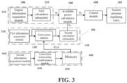
- FIG. 3 illustrates a structural schematic diagram of a power management system provided by the present invention in one embodiment.
- orientation words such as “top”, “bottom”, “upwards” and “downwards” mentioned herein are defined relative to directions in each drawing, are relatively concepts and can change according to different positions and different practical states. Therefore, these or other orientation words shall not be understood as restrictive words.
- FIG. 1 illustrates a structural schematic diagram of a transportation refrigeration unit.
- the transportation refrigeration unit 100 comprises: an engine 110; a power generator 120 and a compressor 130, wherein output power of the engine 110 is transmitted to the power generator 120 and the compressor 130 through a belt or a shaft; and a plurality of electric loads driven by the power generator 120.
- the engine 110 is usually a diesel engine and has output power P e .
- the plurality of electric loads may comprise: a battery 140, a condenser fan 150, an evaporator fan 160, a controller 170, a suction pressure regulating valve 180 supplied with power and controlled by the controller 170, etc..
- the suction pressure regulating valve 180 is provided at an upstream of the compressor 130 and is used for controlling flow of refrigerant passing through the compressor 130.
- These electric loads are driven by the power generator 120.
- the condenser fan 150, the evaporator fan 160 and the controller 170 usually have a demand of relative stable power, while the battery 140 has a demand of variable voltage, because it possibly needs larger power when it needs to be charged and does not consume power when it does not need to be charged.
- the controller 170 can correspondingly give out a control signal to the suction pressure regulating valve 180 to adjust the operating state of the compressor 130 to adapt to the available power P ca .
- the existing power management method has various defects.
- the calculated available power P ca usually is smaller than the power, which can be actually allocated to the compressor, in the output power of the engine. This is because that, in the existing power management method, in order to meet the demands of non-stable power electric loads such as the battery 140, a comparatively high value is adopted as M, resulting that the estimated values of the power needed by the electric loads of the power generator 120 are slightly large and consequently the estimated value of the power allocated to the compressor 130 is reduced. This causes that the compressor 130 does not operate in an optimum state, and the refrigeration capacity and refrigeration efficiency of the compressor are reduced.
- FIG. 2 illustrates a flowchart of a power management method provided by the present invention in one embodiment, wherein the power management method comprises the following steps:
- step of calculating the engine power P e comprises:
- step S22 of one embodiment of the present invention firstly power at rated temperature can be obtained according to engine revolution speed through a revolution speed-power curve, and then the engine power P e is calculated according to the temperature of the engine and a temperature correction curve.
- step of calculating the power generator real-time input power P a comprises:
- step S42 the conversion relationship f(x) is established by means of linear regression.
- step S60 opening of the suction pressure regulating valve 180 at an upstream of the compressor 130 is adjusted to manage the power distributed to the compressor 130.
- FIG. 3 illustrates a structural schematic diagram of a power management system provided by the present invention in one embodiment.
- the illustrated power management system is used for power distribution in a transportation refrigeration unit and comprises:
- engine power calculation module 200 comprises:
- the first calculation submodule 220 may be configured to firstly obtain power at rated temperature according to engine revolution speed through a revolution speed-power curve, and then calculate the engine power P e according to the temperature of the engine and a temperature correction curve.
- the power generator real-time input power calculation module 300 comprises:
- the power management system further comprises a conversion relationship generation module comprising:
- the conversion relationship establishment module 420 is configured to establish the conversion relationship f(x) by means of linear regression.
- control module 600 is configured to: receive the available power P 1 from the available power calculation module 500 and adjust opening of a suction pressure regulating valve 180 at an upstream of the compressor 130 according to the available power P 1 to control the power distributed to the compressor 130.
- the first information acquisition module 310 is coupled to a power generator LIN bus and the second information acquisition module 410 is coupled to the power generator LIN bus and an output current sensor.
- the power generator excitation current I e is acquired from a power generator data output.
- the power generator data output comprises an LIN bus, a CAN bus, a wireless network, a cellular phone network, a bluetooth or the like.
- the conversion relationship f(x) can be stored in the controller.
- the above-mentioned power management method and system can be typically used in the transportation refrigeration unit illustrated in FIG. 1 .
- the power generator real output current I ro simultaneously reflects the power demands of all power generator loads, and can also reflect the power demand of the battery under the situation that the power demands of parts such as the fans and the controller are met.
- the power management method provided by the present invention can more accurately identify real power consumed by the power generator loads in the transportation refrigeration unit, thus the value of power allocated to the power generator to be more accurate and the power is prevented from being wasted. Besides, the power management method provided by the present invention can allocate more power to the compressor in the transportation refrigeration unit, thus the refrigeration capacity is improved, which helps the product to get an environmental certification.
Landscapes
- Engineering & Computer Science (AREA)
- Mechanical Engineering (AREA)
- Physics & Mathematics (AREA)
- Thermal Sciences (AREA)
- General Engineering & Computer Science (AREA)
- Chemical & Material Sciences (AREA)
- Combustion & Propulsion (AREA)
- Devices That Are Associated With Refrigeration Equipment (AREA)
- Air Conditioning Control Device (AREA)
Description
- The present invention relates to the field of refrigeration or cooling, in particular to a power management method for a transportation refrigeration unit and a power management system for a transportation refrigeration unit.
- As known, a mobile refrigeration system is typically arranged on a vehicle, train or other vehicles, so as to provide refrigeration for a partial area in the vehicle, e.g., provide refrigeration in a carriage or container. A mobile refrigeration system is usually used for providing refrigeration during transportation of some cargoes, e.g., providing a low-temperature environment during transportation of food which is easily corrupted or products which need to be preserved at low temperature. A transportation refrigeration unit is commonly arranged in a mobile refrigeration system to control environmental states such as temperature in the mobile refrigeration system. A transportation refrigeration unit typically comprises: an engine used for providing driving force or power; a power generator driven by the engine to supply power to power generator loads, which, for example, may be various fans, controllers, batteries and the like; and a refrigeration loop comprising a compressor providing refrigeration.
- Since the output power of the engine is limited, power distribution needs to be performed between the engine and the compressor. The existing power management method usually causes power actually distributed to the power generator to be slightly larger, and consequently the power distributed to the compressor is reduced. Therefore, the compressor power determined according to a conventional power management method usually does not realize full utilization of the power of the engine, and the refrigeration efficiency of the refrigeration unit is reduced.
- Therefore, there is a continuous demand for an improved power management method and system.
-
WO 2008/153518 A1 discloses an auxiliary power system and method that distributes and controls excess electric power from a trailer box refrigeration system. -
US 2015328953 A1 discloses systems and methods for controlling the amount of power supplied by an engine for a transport refrigeration system to ensure that the engine is operating within a preset window of operation and compliant with emission legislation. - One purpose of the present invention is to provide a power management method, which can increase power distributed to a compressor and improve system efficiency on the premise that power demands of power generator loads are met. Another purpose of the present invention is to provide a power management system.
- The present invention provides a power management method used for power distribution in a transportation refrigeration unit according to claim 1.
- Optionally, the step of calculating the engine power comprises:
- acquiring engine revolution speed and temperature; and
- calculating the engine power according to the engine revolution speed and temperature.
- Optionally, the conversion relationship is generated according to the following method:
- acquiring numerical values of power generator excitation current and power generator output current which correspond to each other;
- establishing a conversion relationship between the power generator excitation current and the power generator output current; and
- storing the conversion relationship.
- Optionally, the conversion relationship is established by means of linear regression.
- Optionally, in a process of managing the power distributed to the compressor, opening of a suction pressure regulating valve at an upstream of the compressor is adjusted to manage the power distributed to the compressor.
- According to a second aspect of the invention, a power management system used for power distribution in a transportation refrigeration unit is provided according to claim 6.
- Optionally, the engine power calculation module comprises:
- an engine information acquisition module configured to acquire engine revolution speed and temperature; and
- a first calculation submodule used for receiving engine revolution speed and temperature and configured to calculate the engine power according to the engine revolution speed and temperature.
- Optionally, the power management system further comprises a conversion relationship generation module comprising:
- a second information acquisition module configured to acquire numerical values of power generator excitation current and power generator output current which correspond to each other;
- a conversion relationship establishment module configured to receive the numerical values of power generator excitation current and power generator output current which correspond to each other from the second information acquisition module, and establish a conversion relationship between the power generator excitation current and the power generator output current; and
- a memory configured to acquire the conversion relationship from the conversion relationship establishment module and store the conversion relationship.
- Optionally, the conversion relationship establishment module is configured to establish the conversion relationship by means of linear regression.
- Optionally, the control module is configured to: receive the available power from the available power calculation module and adjust opening of a suction pressure regulating valve at an upstream of the compressor according to the available power to control the power distributed to the compressor.
- Optionally, the first information acquisition module is coupled to a power generator LIN bus and the second information acquisition module is coupled to the power generator LIN bus and an output current sensor.
- The power management method and system provided by the present invention have the advantages of simplicity, reliability, stable operation and the like, the power generator real-time input power can be calculated according to the power generator excitation current, thus more power can be provided to the compressor on the premise that the power supply to power generator loads is guaranteed, and the operating efficiency of the transportation refrigeration unit is improved. Besides, the power management method and system provided by the present invention can adaptively change under the situation that the power generator loads change, and thus the system compatibility is improved.
- The present invention will be further described below in detail with reference to the drawings in combination with the preferred embodiments. However, one skilled in the art shall understand that these drawings are drawn for the purpose of explaining the preferred embodiments and thus shall not be used as limitations to the scope of the present invention. The scope is defined in the appended claims. Besides, unless otherwise pointed out, the drawings are just used for conceptually illustrating the components or structures of the described objects, possibly contain exaggerated illustration and are not certainly drawn according to scales.
-
FIG. 1 illustrates a structural schematic diagram of a transportation refrigeration unit. -
FIG. 2 illustrates a flowchart of a power management method provided by the present invention in one embodiment. -
FIG. 3 illustrates a structural schematic diagram of a power management system provided by the present invention in one embodiment. - The preferred embodiments of the present invention will be described below in detail with reference to the drawings. One skilled in the art shall understand that these descriptions are just descriptive and exemplary and shall not be explained as limitations to the protective scope of the present invention.
- Firstly, it needs to be stated that orientation words such as "top", "bottom", "upwards" and "downwards" mentioned herein are defined relative to directions in each drawing, are relatively concepts and can change according to different positions and different practical states. Therefore, these or other orientation words shall not be understood as restrictive words.
- Besides, it also needs to be pointed out that any individual technical features described or implied in the embodiments herein or any individual technical features illustrated or implied in the drawings can still be continuously combined between these technical features (or equivalents thereof), so as to obtain other embodiments of the present invention directly mentioned herein.
- It shall be noted that the same reference signs in different drawings represent the same or approximately same components.
-
FIG. 1 illustrates a structural schematic diagram of a transportation refrigeration unit. Herein, the transportation refrigeration unit 100 comprises: anengine 110; a power generator 120 and acompressor 130, wherein output power of theengine 110 is transmitted to the power generator 120 and thecompressor 130 through a belt or a shaft; and a plurality of electric loads driven by the power generator 120. - Herein, the
engine 110 is usually a diesel engine and has output power Pe. - The plurality of electric loads may comprise: a
battery 140, a condenser fan 150, anevaporator fan 160, acontroller 170, a suction pressure regulating valve 180 supplied with power and controlled by thecontroller 170, etc.. The suction pressure regulating valve 180 is provided at an upstream of thecompressor 130 and is used for controlling flow of refrigerant passing through thecompressor 130. These electric loads are driven by the power generator 120. Herein, during operation, the condenser fan 150, theevaporator fan 160 and thecontroller 170 usually have a demand of relative stable power, while thebattery 140 has a demand of variable voltage, because it possibly needs larger power when it needs to be charged and does not consume power when it does not need to be charged. - Since the output power Pe of the
engine 110 is usually limited and stable, power needs to be distributed between the power generator 120 and thecompressor 130. In the existing power management method, power distributed to thecompressor 130 is determined according to the following method: - (1) acquiring power demands of relatively stable parts of the plurality of electric loads, such as power demand Pcfm of the condenser fan 150, power demand Pefm of the
evaporator fan 160 and power demand Pc of thecontroller 170; - (2) acquiring a safety margin M according to parts having variable power demands in the plurality of electric loads;
- (3) acquiring efficiency E of the power generator 120, which can be determined according to a known method in the art; and
- (4) acquiring available power Pca of the
compressor 130 according to the following formula:
- After the available power Pca of the
compressor 130 is determined, thecontroller 170 can correspondingly give out a control signal to the suction pressure regulating valve 180 to adjust the operating state of thecompressor 130 to adapt to the available power Pca. - However, the existing power management method has various defects. During operation, the calculated available power Pca usually is smaller than the power, which can be actually allocated to the compressor, in the output power of the engine. This is because that, in the existing power management method, in order to meet the demands of non-stable power electric loads such as the
battery 140, a comparatively high value is adopted as M, resulting that the estimated values of the power needed by the electric loads of the power generator 120 are slightly large and consequently the estimated value of the power allocated to thecompressor 130 is reduced. This causes that thecompressor 130 does not operate in an optimum state, and the refrigeration capacity and refrigeration efficiency of the compressor are reduced. - In order to solve the above-mentioned problem, the present invention provides a power management method for a transportation refrigeration unit.
FIG. 2 illustrates a flowchart of a power management method provided by the present invention in one embodiment, wherein the power management method comprises the following steps: - calculating power generator real-time input power Pa according to power generator excitation current Ie;
- calculating engine power Pe according to engine operating parameters;
- calculating available power P1 based on the power generator real-time input power Pa and the engine power Pe; and
- managing power distributed to a compressor based on the available power P1.
- Further, the step of calculating the engine power Pe comprises:
- step S21: acquiring engine revolution speed and temperature, which can be completed by a sensor arranged on the engine or can be acquired according to LIN data output of the engine; and
- step S22: calculating the engine power Pe according to the engine revolution speed and temperature. A specific method for calculating the engine power Pe is known by one skilled in the art, and thus is not described in detail herein.
- In step S22 of one embodiment of the present invention, firstly power at rated temperature can be obtained according to engine revolution speed through a revolution speed-power curve, and then the engine power Pe is calculated according to the temperature of the engine and a temperature correction curve.
- Further, the step of calculating the power generator real-time input power Pa comprises:
- step S31a: acquiring power generator efficiency E;
- step S31b: acquiring power generator excitation current Ie;
- step S31c: acquiring power generator voltage U;
- step S32a: acquiring a conversion relationship f(x);
- step S32b: substituting the power generator excitation current Ie into the conversion relationship f(x) for conversion;
- step S32c: obtaining power generator real output current Iro; and
- step S33: multiplying the power generator real output current Iro by the power generator voltage U and dividing by the power generator efficiency E to calculate the power generator real-time input power Pa, i.e.:

- Further, the conversion relationship f(x) is generated according to the following method:
- step S41: acquiring numerical values of power generator excitation current Ie and power generator output current Iro which correspond to each other;
- step S42: establishing a conversion relationship f(x) between the power generator excitation current Ie and the power generator output current Iro; and
- step S43: storing the conversion relationship f(x).
- In one embodiment of the present invention, in step S42, the conversion relationship f(x) is established by means of linear regression.
- According to one example of data fitting of the present invention, the power generator real output current and the excitation current approximately have a linear relationship therebetween, and the relationship therebetween can be expressed by using a formula y=0.0272x+0.0089, and a certainty coefficient R2 is 0.9959.
- Further, in step S50, the available power P1 is calculated by subtracting the power generator real-time input power Pa from the engine power Pe, i.e.:

- Further, in step S60, opening of the suction pressure regulating valve 180 at an upstream of the
compressor 130 is adjusted to manage the power distributed to thecompressor 130. -
FIG. 3 illustrates a structural schematic diagram of a power management system provided by the present invention in one embodiment. The illustrated power management system is used for power distribution in a transportation refrigeration unit and comprises: - an engine power calculation module 200 used for calculating engine power Pe according to engine operating parameters;
- a power generator real-time input power calculation module 300 used for calculating power generator real-time input power Pa according to power generator excitation current Ie;
- an available power calculation module 500 used for receiving the power generator real-time input power Pe and the engine power Pa and configured to calculate available power P1 based on the power generator real-time input power Pe and the engine power Pa; and
- a control module 600 used for receiving the available power P1 and configured to manage power distributed to a
compressor 130 based on the available power P1. - Further, the engine power calculation module 200 comprises:
- an engine information acquisition module 210 configured to acquire engine revolution speed and temperature, wherein in one embodiment of the present invention, the engine information acquisition module 210 is a sensor arranged on the engine and/or an LIN data output of the engine; and
- a first calculation submodule 220 used for receiving engine revolution speed and temperature and configured to calculate the engine power according to the engine revolution speed and temperature. A specific method for calculating the engine power Pe is known by one skilled in the art, and thus is not described in detail herein.
- In one embodiment of the present invention, the first calculation submodule 220 may be configured to firstly obtain power at rated temperature according to engine revolution speed through a revolution speed-power curve, and then calculate the engine power Pe according to the temperature of the engine and a temperature correction curve.
- Further, the power generator real-time input power calculation module 300 comprises:
- a first information acquisition module 310 configured to acquire power generator efficiency E, power generator excitation current Ie and power generator voltage U;
- a
conversion module 320 configured to acquire the power generator excitation current Ie from the first information acquisition module 310, acquire a conversion relationship f(x) from a memory 420, and convert the power generator excitation current Ie according to the conversion relationship f(x) to obtain power generator real output current Iro; and - a second calculation submodule 330 configured to receive the power generator real output current Iro from the
conversion module 320 and receive the power generator efficiency E and the power generator voltage U from the first information acquisition module, and configured to multiply the power generator real output current Iro by the power generator voltage U and divide by the power generator efficiency E to calculate the power generator real-time input power Pa, i.e.:
- Further, the power management system further comprises a conversion relationship generation module comprising:
- a second information acquisition module 410 configured to acquire numerical values of power generator excitation current Ie and power generator output current Iro which correspond to each other;
- a conversion relationship establishment module 420 configured to receive the numerical values of power generator excitation current Ie and power generator output current Iro which correspond to each other from the second information acquisition module 410, and establish a conversion relationship f(x) between the power generator excitation current Ie and the power generator output current Iro; and
- a memory 430 configured to acquire the conversion relationship f(x) from the conversion relationship establishment module 420 and store the conversion relationship f(x).
- Further, the conversion relationship establishment module 420 is configured to establish the conversion relationship f(x) by means of linear regression.
- Further, the available power calculation module 500 is configured to: receive the engine power Pe from the engine power calculation module 200, receive the power generator real-time input power Pa from the power generator real-time input power calculation module 300, and calculate the available power P1 by subtracting the power generator real-time input power Pa from the engine power Pe, i.e.:

- Further, the control module 600 is configured to: receive the available power P1 from the available power calculation module 500 and adjust opening of a suction pressure regulating valve 180 at an upstream of the
compressor 130 according to the available power P1 to control the power distributed to thecompressor 130. - Alternatively, the first information acquisition module 310 is coupled to a power generator LIN bus and the second information acquisition module 410 is coupled to the power generator LIN bus and an output current sensor.
- Alternatively, the power generator excitation current Ie is acquired from a power generator data output. The power generator data output comprises an LIN bus, a CAN bus, a wireless network, a cellular phone network, a bluetooth or the like.
- Alternatively, after the conversion relationship f(x) is obtained, the conversion relationship f(x) can be stored in the controller.
- The above-mentioned power management method and system can be typically used in the transportation refrigeration unit illustrated in
FIG. 1 . During operation, the power generator real output current Iro simultaneously reflects the power demands of all power generator loads, and can also reflect the power demand of the battery under the situation that the power demands of parts such as the fans and the controller are met. - The power management method provided by the present invention can more accurately identify real power consumed by the power generator loads in the transportation refrigeration unit, thus the value of power allocated to the power generator to be more accurate and the power is prevented from being wasted. Besides, the power management method provided by the present invention can allocate more power to the compressor in the transportation refrigeration unit, thus the refrigeration capacity is improved, which helps the product to get an environmental certification.
- The description discloses the present invention with reference to the drawings and also enables one skilled in the art to be capable of implementing the present invention, including manufacturing and using any devices or systems, selecting suitable materials and using any combined methods. The scope of the present invention, which is defined by the claims, contains other examples which can be conceived by one skilled in the art.
Claims (11)
- A power management method used for power distribution in a transportation refrigeration unit (100), the transportation refrigeration unit comprising: an engine (110); a power generator (120) and a compressor (130), wherein output power of the engine is transmitted to the power generator and the compressor through a belt or a shaft, and wherein the power management method comprises the following steps:
calculating (S22) engine power according to engine operating parameters (S21), characterized by:calculating (S33) power generator real-time input power according to power generator excitation current (S31b);calculating (S50) available power based on the power generator real-time input power and the engine power wherein, in the process of calculating (S50) the available power, the available power is calculated by subtracting the power generator real-time input power from the engine power; andmanaging (S60) power distributed to the compressor based on the available power,wherein the step of calculating the power generator real-time input power comprises:acquiring power generator efficiency (S31a), power generator excitation current (S31b) and power generator voltage (S31c);acquiring (S32a) a conversion relationship and substituting (S32b) the power generator excitation current into the conversion relationship to obtain (S32c) power generator real output current; andmultiplying (S33) the power generator real output current by the power generator voltage and dividing by the power generator efficiency to calculate the power generator real-time input power. - The power management method according to claim 1, wherein the step of calculating the engine power comprises:acquiring engine revolution speed and temperature; andcalculating (S22) the engine power according to the engine revolution speed and temperature.
- The power management method according to claim 1, wherein the conversion relationship is generated according to the following method:acquiring (S41) numerical values of power generator excitation current and power generator output current which correspond to each other;establishing (S42) a conversion relationship between the power generator excitation current and the power generator output current; andstoring (S43) the conversion relationship.
- The power management method according to claim 3, wherein the conversion relationship is established by means of linear regression.
- The power management method according to claim 1, wherein, in a process of managing (S60) the power distributed to the compressor (130), opening of a suction pressure regulating valve (180) at an upstream of the compressor is adjusted to manage the power distributed to the compressor.
- A power management system used for power distribution in a transportation refrigeration unit (100), the transportation refrigeration unit comprising: an engine (110); a power generator (120) and a compressor (130), wherein output power of the engine is transmitted to the power generator and the compressor through a belt or a shaft, and wherein the power management system comprises:an engine power calculation module (200) used for calculating engine power according to engine operating parameters,characterized by:a power generator real-time input power calculation module (300) used for calculating power generator real-time input power according to power generator excitation current;an available power calculation module (500) used for receiving the power generator real-time input power and the engine power and configured to calculate available power based on the power generator real-time input power and the engine power wherein the available power calculation module (500) is configured to: receive the engine power from the engine power calculation module, receive the power generator real-time input power from the power generator real-time input power calculation module, and calculate the available power by subtracting the power generator real-time input power from the engine power;a control module (600) used for receiving the available power and configured to manage power distributed to a compressor based on the available power, andwherein the power generator real-time input power calculation module (300) comprises:a first information acquisition module (310) configured to acquire power generator efficiency, power generator excitation current and power generator voltage;a conversion module (320) configured to receive a conversion relationship from a memory (430), receive the power generator excitation current from the first information acquisition module and convert the power generator excitation current according to the conversion relationship to obtain power generator real output current; anda second calculation submodule (330) configured to receive the power generator real output current from the conversion module and receive the power generator efficiency and the power generator voltage from the first information acquisition module, and configured to multiply the power generator real output current by the power generator voltage and divide by the power generator efficiency to calculate the power generator real-time input power.
- The power management system according to claim 6, wherein the engine power calculation module (300) comprises:an engine information acquisition module (210) configured to acquire engine revolution speed and temperature; anda first calculation submodule (220) used for receiving engine revolution speed and temperature and configured to calculate the engine power according to the engine revolution speed and temperature.
- The power management system according to claim 6, wherein the power management system further comprises a conversion relationship generation module (400) comprising:a second information acquisition module (410) configured to acquire numerical values of power generator excitation current and power generator output current which correspond to each other;a conversion relationship establishment module (420) configured to receive the numerical values of power generator excitation current and power generator output current which correspond to each other from the second information acquisition module, and establish a conversion relationship between the power generator excitation current and the power generator output current; anda memory (430) configured to acquire the conversion relationship from the conversion relationship establishment module and store the conversion relationship.
- The power management system according to claim 8, wherein the conversion relationship establishment module (420) is configured to establish the conversion relationship by means of linear regression.
- The power management system according to claim 6, wherein the control module (600) is configured to: receive the available power from the available power calculation module and adjust opening of a suction pressure regulating valve (180) at an upstream of the compressor (130) according to the available power to control the power distributed to the compressor.
- The power management system according to claim 8, wherein the first information acquisition module (310) is coupled to a power generator LIN bus and the second information acquisition module (410) is coupled to the power generator LIN bus and an output current sensor.
Applications Claiming Priority (2)
| Application Number | Priority Date | Filing Date | Title |
|---|---|---|---|
| CN201710224011.1A CN108688439A (en) | 2017-04-07 | 2017-04-07 | Power management method and system for transport refrigeration unit |
| PCT/US2018/025995 WO2018187405A1 (en) | 2017-04-07 | 2018-04-04 | Power managing method and system for transportation refrigeration unit |
Publications (2)
| Publication Number | Publication Date |
|---|---|
| EP3606777A1 EP3606777A1 (en) | 2020-02-12 |
| EP3606777B1 true EP3606777B1 (en) | 2024-11-27 |
Family
ID=62028155
Family Applications (1)
| Application Number | Title | Priority Date | Filing Date |
|---|---|---|---|
| EP18719398.2A Active EP3606777B1 (en) | 2017-04-07 | 2018-04-04 | Power managing method and system for transportation refrigeration unit |
Country Status (4)
| Country | Link |
|---|---|
| US (1) | US11453269B2 (en) |
| EP (1) | EP3606777B1 (en) |
| CN (1) | CN108688439A (en) |
| WO (1) | WO2018187405A1 (en) |
Families Citing this family (3)
| Publication number | Priority date | Publication date | Assignee | Title |
|---|---|---|---|---|
| CN112440152B (en) * | 2020-11-09 | 2022-04-12 | 北京三一智造科技有限公司 | Milling control method and device, expert database model training method and device |
| CN112347584B (en) * | 2020-11-09 | 2024-05-28 | 北京三一智造科技有限公司 | Power distribution method and power distribution device |
| CN114193999B (en) * | 2021-12-16 | 2023-05-16 | 东风汽车集团股份有限公司 | Method for determining power of compressor of electric automobile thermal management system and storage medium |
Citations (1)
| Publication number | Priority date | Publication date | Assignee | Title |
|---|---|---|---|---|
| US20150328953A1 (en) * | 2012-12-27 | 2015-11-19 | Thermo King Corporation | Systems and methods for engine power control for transport refrigeration system |
Family Cites Families (32)
| Publication number | Priority date | Publication date | Assignee | Title |
|---|---|---|---|---|
| US4642770A (en) * | 1985-04-18 | 1987-02-10 | Deere & Company | Vehicle accessory control system |
| US6622505B2 (en) | 2001-06-08 | 2003-09-23 | Thermo King Corporation | Alternator/invertor refrigeration unit |
| US6487869B1 (en) | 2001-11-06 | 2002-12-03 | Themo King Corporation | Compressor capacity control system |
| US7412842B2 (en) | 2004-04-27 | 2008-08-19 | Emerson Climate Technologies, Inc. | Compressor diagnostic and protection system |
| FR2886410B1 (en) * | 2005-05-31 | 2007-08-31 | Valeo Equip Electr Moteur | METHOD AND DEVICE FOR ESTIMATING THE CURRENT DELIVERED BY AN ALTENATOR FOR A MOTOR VEHICLE |
| US7486053B2 (en) | 2005-06-17 | 2009-02-03 | Hamilton Sundstrand Corporation | Power manager for an electrical power generator |
| US20060288714A1 (en) | 2005-06-25 | 2006-12-28 | Joyner Jack S | Refrigeration fan motor controller for ECM |
| JP5210542B2 (en) * | 2007-05-11 | 2013-06-12 | 三菱重工業株式会社 | Transportation refrigeration equipment |
| BRPI0721710A2 (en) * | 2007-06-07 | 2013-01-22 | Carrier Corp | Method and system for electric power supply for auxiliary electric loads |
| WO2009029205A1 (en) * | 2007-08-30 | 2009-03-05 | Dimplex Thermal Solutions | Refrigeration power system for a storage compartment in a vehicle |
| EP2464920B1 (en) | 2009-08-10 | 2019-05-22 | Carrier Corporation | Power savings apparatus for transport refrigeration system, transport refrigeration unit, and methods for same |
| DK2528759T3 (en) | 2010-01-29 | 2014-12-15 | Carrier Corp | Solar assisted transport cooling system, transport refrigeration units and methods thereof |
| US8393171B2 (en) * | 2010-04-13 | 2013-03-12 | Gerald Allen Alston | Mechanically enhanced ejector HVAC and electric power generation system |
| JP5447288B2 (en) * | 2010-08-16 | 2014-03-19 | 株式会社デンソー | Vehicle control device |
| WO2012047499A2 (en) | 2010-09-28 | 2012-04-12 | Carrier Corporation | Operation of transport refrigeration systems to prevent engine stall and overload |
| US8723458B1 (en) | 2010-11-19 | 2014-05-13 | Billy Chambers | Soft start drive for mobile refrigeration unit |
| EP2844506B1 (en) | 2012-05-01 | 2021-03-31 | Carrier Corporation | Transport refrigeration system having electric fans |
| WO2014120651A1 (en) * | 2013-01-30 | 2014-08-07 | Trane International Inc. | Multiple load control for variable frequency drive harmonic mitigation |
| KR101509944B1 (en) * | 2013-10-22 | 2015-04-07 | 현대자동차주식회사 | Control method of air conditioner |
| US9702605B2 (en) | 2013-12-05 | 2017-07-11 | Ford Global Technologies, Llc | Method for adjusting fan and compressor power for a vehicle cabin heating system |
| WO2015100398A1 (en) * | 2013-12-26 | 2015-07-02 | Thermo King Corporation | Method and system for dynamic power allocation in a transport refrigeration system |
| DE102014211625A1 (en) * | 2014-06-17 | 2015-12-17 | Robert Bosch Gmbh | Power control device for a motor control device, engine control device and engine system |
| JP6327038B2 (en) * | 2014-07-23 | 2018-05-23 | 株式会社デンソー | Air conditioner for vehicles |
| US9714037B2 (en) | 2014-08-18 | 2017-07-25 | Trimble Navigation Limited | Detection of driver behaviors using in-vehicle systems and methods |
| JP6375932B2 (en) * | 2014-12-18 | 2018-08-22 | 株式会社デンソー | Air conditioner for vehicles |
| US10723201B2 (en) * | 2015-08-31 | 2020-07-28 | Thermo King Corporation | Methods and systems to control engine loading on a transport refrigeration system |
| JP6597175B2 (en) * | 2015-10-26 | 2019-10-30 | 株式会社デンソー | Evaluation device |
| CN108351140B (en) * | 2015-11-03 | 2021-07-09 | 开利公司 | Transport refrigeration system and method of operation |
| US10676077B2 (en) * | 2015-12-10 | 2020-06-09 | Cummins, Inc. | Systems and methods of energy management and control of vehicle accessories |
| WO2017139148A1 (en) * | 2016-02-10 | 2017-08-17 | Carrier Corporation | Power management for co2 transportation refrigeration system |
| US9802617B1 (en) * | 2016-05-12 | 2017-10-31 | Nissan North America, Inc. | Vehicle accessory power management assembly |
| RU2728965C1 (en) * | 2017-04-05 | 2020-08-03 | Ниссан Мотор Ко., Лтд. | Method of controlling vehicle air conditioning and vehicle air conditioning device |
-
2017
- 2017-04-07 CN CN201710224011.1A patent/CN108688439A/en active Pending
-
2018
- 2018-04-04 EP EP18719398.2A patent/EP3606777B1/en active Active
- 2018-04-04 WO PCT/US2018/025995 patent/WO2018187405A1/en not_active Ceased
- 2018-04-04 US US16/500,961 patent/US11453269B2/en active Active
Patent Citations (1)
| Publication number | Priority date | Publication date | Assignee | Title |
|---|---|---|---|---|
| US20150328953A1 (en) * | 2012-12-27 | 2015-11-19 | Thermo King Corporation | Systems and methods for engine power control for transport refrigeration system |
Also Published As
| Publication number | Publication date |
|---|---|
| US11453269B2 (en) | 2022-09-27 |
| WO2018187405A1 (en) | 2018-10-11 |
| CN108688439A (en) | 2018-10-23 |
| EP3606777A1 (en) | 2020-02-12 |
| US20200031201A1 (en) | 2020-01-30 |
Similar Documents
| Publication | Publication Date | Title |
|---|---|---|
| EP3919320B1 (en) | Thermal management method for battery pack | |
| US10464547B2 (en) | Vehicle with model-based route energy prediction, correction, and optimization | |
| US8935043B2 (en) | Temperature compensated battery parameter estimation | |
| US10704818B2 (en) | Method and system for dynamic power allocation in a transport refrigeration system | |
| US7917276B2 (en) | Vehicle-use power supply apparatus | |
| EP2256341B2 (en) | System and method for controlling a wind farm | |
| US11807125B2 (en) | Method for optimally managing the charging of a fleet of electric vehicles | |
| EP3606777B1 (en) | Power managing method and system for transportation refrigeration unit | |
| US9709037B2 (en) | System and method for controlling wind turbines in wind farms | |
| US10843588B2 (en) | Method and system for power management using a power converter in transport | |
| EP3667207B1 (en) | Control device, transport refrigeration system, and control method | |
| EP4238789B1 (en) | Proactive adjustment of transport refrigeration units | |
| US9555719B2 (en) | System and method for optimizing hybrid vehicle battery usage constraints | |
| EP4099454A1 (en) | Methods and systems for managing and implementing state-of-health to control lifespan of a fuel cell | |
| EP4373710A1 (en) | Determining battery or solar panel capacity for an electric refrigeration unit | |
| US20170043757A1 (en) | Mild hybrid powertrain controls | |
| EP3692315B1 (en) | Multi power converter unit for a trailer refrigeration unit | |
| KR102123607B1 (en) | Remote control monitoring system and method for a plurality of energy storage devices (ESS) capable of maximum operation efficiency management | |
| CN112622649A (en) | Power generation control system and method for series-connection extended-range new energy vehicle | |
| JP2020145884A (en) | Charge control system | |
| EP3086979B1 (en) | Method and system for dynamic power allocation in a transport refrigeration system | |
| EP3741605B1 (en) | Temperature controlled goods vehicles | |
| JP2013070466A (en) | Cooling device for electric vehicle | |
| EP4122742A1 (en) | A method for thermal conditioning of a thermal buffer in a vehicle | |
| US20220314960A1 (en) | Method for managing a torque to be supplied by an electric motor |
Legal Events
| Date | Code | Title | Description |
|---|---|---|---|
| STAA | Information on the status of an ep patent application or granted ep patent |
Free format text: STATUS: UNKNOWN |
|
| STAA | Information on the status of an ep patent application or granted ep patent |
Free format text: STATUS: THE INTERNATIONAL PUBLICATION HAS BEEN MADE |
|
| PUAI | Public reference made under article 153(3) epc to a published international application that has entered the european phase |
Free format text: ORIGINAL CODE: 0009012 |
|
| STAA | Information on the status of an ep patent application or granted ep patent |
Free format text: STATUS: REQUEST FOR EXAMINATION WAS MADE |
|
| 17P | Request for examination filed |
Effective date: 20191029 |
|
| AK | Designated contracting states |
Kind code of ref document: A1 Designated state(s): AL AT BE BG CH CY CZ DE DK EE ES FI FR GB GR HR HU IE IS IT LI LT LU LV MC MK MT NL NO PL PT RO RS SE SI SK SM TR |
|
| AX | Request for extension of the european patent |
Extension state: BA ME |
|
| DAV | Request for validation of the european patent (deleted) | ||
| DAX | Request for extension of the european patent (deleted) | ||
| STAA | Information on the status of an ep patent application or granted ep patent |
Free format text: STATUS: EXAMINATION IS IN PROGRESS |
|
| 17Q | First examination report despatched |
Effective date: 20211208 |
|
| RAP3 | Party data changed (applicant data changed or rights of an application transferred) |
Owner name: CARRIER CORPORATION |
|
| GRAP | Despatch of communication of intention to grant a patent |
Free format text: ORIGINAL CODE: EPIDOSNIGR1 |
|
| STAA | Information on the status of an ep patent application or granted ep patent |
Free format text: STATUS: GRANT OF PATENT IS INTENDED |
|
| INTG | Intention to grant announced |
Effective date: 20240709 |
|
| GRAS | Grant fee paid |
Free format text: ORIGINAL CODE: EPIDOSNIGR3 |
|
| GRAA | (expected) grant |
Free format text: ORIGINAL CODE: 0009210 |
|
| STAA | Information on the status of an ep patent application or granted ep patent |
Free format text: STATUS: THE PATENT HAS BEEN GRANTED |
|
| AK | Designated contracting states |
Kind code of ref document: B1 Designated state(s): AL AT BE BG CH CY CZ DE DK EE ES FI FR GB GR HR HU IE IS IT LI LT LU LV MC MK MT NL NO PL PT RO RS SE SI SK SM TR |
|
| REG | Reference to a national code |
Ref country code: GB Ref legal event code: FG4D |
|
| REG | Reference to a national code |
Ref country code: CH Ref legal event code: EP |
|
| REG | Reference to a national code |
Ref country code: NL Ref legal event code: FP |
|
| REG | Reference to a national code |
Ref country code: IE Ref legal event code: FG4D |
|
| REG | Reference to a national code |
Ref country code: DE Ref legal event code: R096 Ref document number: 602018076938 Country of ref document: DE |
|
| REG | Reference to a national code |
Ref country code: LT Ref legal event code: MG9D |
|
| PG25 | Lapsed in a contracting state [announced via postgrant information from national office to epo] |
Ref country code: HR Free format text: LAPSE BECAUSE OF FAILURE TO SUBMIT A TRANSLATION OF THE DESCRIPTION OR TO PAY THE FEE WITHIN THE PRESCRIBED TIME-LIMIT Effective date: 20241127 Ref country code: IS Free format text: LAPSE BECAUSE OF FAILURE TO SUBMIT A TRANSLATION OF THE DESCRIPTION OR TO PAY THE FEE WITHIN THE PRESCRIBED TIME-LIMIT Effective date: 20250327 Ref country code: PT Free format text: LAPSE BECAUSE OF FAILURE TO SUBMIT A TRANSLATION OF THE DESCRIPTION OR TO PAY THE FEE WITHIN THE PRESCRIBED TIME-LIMIT Effective date: 20250327 |
|
| PG25 | Lapsed in a contracting state [announced via postgrant information from national office to epo] |
Ref country code: FI Free format text: LAPSE BECAUSE OF FAILURE TO SUBMIT A TRANSLATION OF THE DESCRIPTION OR TO PAY THE FEE WITHIN THE PRESCRIBED TIME-LIMIT Effective date: 20241127 |
|
| PGFP | Annual fee paid to national office [announced via postgrant information from national office to epo] |
Ref country code: NL Payment date: 20250319 Year of fee payment: 8 |
|
| REG | Reference to a national code |
Ref country code: AT Ref legal event code: MK05 Ref document number: 1745389 Country of ref document: AT Kind code of ref document: T Effective date: 20241127 |
|
| PG25 | Lapsed in a contracting state [announced via postgrant information from national office to epo] |
Ref country code: BG Free format text: LAPSE BECAUSE OF FAILURE TO SUBMIT A TRANSLATION OF THE DESCRIPTION OR TO PAY THE FEE WITHIN THE PRESCRIBED TIME-LIMIT Effective date: 20241127 |
|
| PG25 | Lapsed in a contracting state [announced via postgrant information from national office to epo] |
Ref country code: ES Free format text: LAPSE BECAUSE OF FAILURE TO SUBMIT A TRANSLATION OF THE DESCRIPTION OR TO PAY THE FEE WITHIN THE PRESCRIBED TIME-LIMIT Effective date: 20241127 |
|
| PG25 | Lapsed in a contracting state [announced via postgrant information from national office to epo] |
Ref country code: NO Free format text: LAPSE BECAUSE OF FAILURE TO SUBMIT A TRANSLATION OF THE DESCRIPTION OR TO PAY THE FEE WITHIN THE PRESCRIBED TIME-LIMIT Effective date: 20250227 |
|
| PG25 | Lapsed in a contracting state [announced via postgrant information from national office to epo] |
Ref country code: LV Free format text: LAPSE BECAUSE OF FAILURE TO SUBMIT A TRANSLATION OF THE DESCRIPTION OR TO PAY THE FEE WITHIN THE PRESCRIBED TIME-LIMIT Effective date: 20241127 Ref country code: AT Free format text: LAPSE BECAUSE OF FAILURE TO SUBMIT A TRANSLATION OF THE DESCRIPTION OR TO PAY THE FEE WITHIN THE PRESCRIBED TIME-LIMIT Effective date: 20241127 Ref country code: GR Free format text: LAPSE BECAUSE OF FAILURE TO SUBMIT A TRANSLATION OF THE DESCRIPTION OR TO PAY THE FEE WITHIN THE PRESCRIBED TIME-LIMIT Effective date: 20250228 |
|
| PG25 | Lapsed in a contracting state [announced via postgrant information from national office to epo] |
Ref country code: PL Free format text: LAPSE BECAUSE OF FAILURE TO SUBMIT A TRANSLATION OF THE DESCRIPTION OR TO PAY THE FEE WITHIN THE PRESCRIBED TIME-LIMIT Effective date: 20241127 |
|
| PG25 | Lapsed in a contracting state [announced via postgrant information from national office to epo] |
Ref country code: RS Free format text: LAPSE BECAUSE OF FAILURE TO SUBMIT A TRANSLATION OF THE DESCRIPTION OR TO PAY THE FEE WITHIN THE PRESCRIBED TIME-LIMIT Effective date: 20250227 |
|
| PG25 | Lapsed in a contracting state [announced via postgrant information from national office to epo] |
Ref country code: SM Free format text: LAPSE BECAUSE OF FAILURE TO SUBMIT A TRANSLATION OF THE DESCRIPTION OR TO PAY THE FEE WITHIN THE PRESCRIBED TIME-LIMIT Effective date: 20241127 |
|
| PGFP | Annual fee paid to national office [announced via postgrant information from national office to epo] |
Ref country code: DE Payment date: 20250319 Year of fee payment: 8 |
|
| PG25 | Lapsed in a contracting state [announced via postgrant information from national office to epo] |
Ref country code: DK Free format text: LAPSE BECAUSE OF FAILURE TO SUBMIT A TRANSLATION OF THE DESCRIPTION OR TO PAY THE FEE WITHIN THE PRESCRIBED TIME-LIMIT Effective date: 20241127 |
|
| PG25 | Lapsed in a contracting state [announced via postgrant information from national office to epo] |
Ref country code: EE Free format text: LAPSE BECAUSE OF FAILURE TO SUBMIT A TRANSLATION OF THE DESCRIPTION OR TO PAY THE FEE WITHIN THE PRESCRIBED TIME-LIMIT Effective date: 20241127 |
|
| PG25 | Lapsed in a contracting state [announced via postgrant information from national office to epo] |
Ref country code: RO Free format text: LAPSE BECAUSE OF FAILURE TO SUBMIT A TRANSLATION OF THE DESCRIPTION OR TO PAY THE FEE WITHIN THE PRESCRIBED TIME-LIMIT Effective date: 20241127 |
|
| PG25 | Lapsed in a contracting state [announced via postgrant information from national office to epo] |
Ref country code: SK Free format text: LAPSE BECAUSE OF FAILURE TO SUBMIT A TRANSLATION OF THE DESCRIPTION OR TO PAY THE FEE WITHIN THE PRESCRIBED TIME-LIMIT Effective date: 20241127 |
|
| PG25 | Lapsed in a contracting state [announced via postgrant information from national office to epo] |
Ref country code: CZ Free format text: LAPSE BECAUSE OF FAILURE TO SUBMIT A TRANSLATION OF THE DESCRIPTION OR TO PAY THE FEE WITHIN THE PRESCRIBED TIME-LIMIT Effective date: 20241127 |
|
| PG25 | Lapsed in a contracting state [announced via postgrant information from national office to epo] |
Ref country code: IT Free format text: LAPSE BECAUSE OF FAILURE TO SUBMIT A TRANSLATION OF THE DESCRIPTION OR TO PAY THE FEE WITHIN THE PRESCRIBED TIME-LIMIT Effective date: 20241127 |
|
| REG | Reference to a national code |
Ref country code: DE Ref legal event code: R097 Ref document number: 602018076938 Country of ref document: DE |
|
| PG25 | Lapsed in a contracting state [announced via postgrant information from national office to epo] |
Ref country code: SE Free format text: LAPSE BECAUSE OF FAILURE TO SUBMIT A TRANSLATION OF THE DESCRIPTION OR TO PAY THE FEE WITHIN THE PRESCRIBED TIME-LIMIT Effective date: 20241127 |
|
| PLBE | No opposition filed within time limit |
Free format text: ORIGINAL CODE: 0009261 |
|
| STAA | Information on the status of an ep patent application or granted ep patent |
Free format text: STATUS: NO OPPOSITION FILED WITHIN TIME LIMIT |
|
| REG | Reference to a national code |
Ref country code: CH Ref legal event code: L10 Free format text: ST27 STATUS EVENT CODE: U-0-0-L10-L00 (AS PROVIDED BY THE NATIONAL OFFICE) Effective date: 20251008 |
|
| 26N | No opposition filed |
Effective date: 20250828 |
|
| REG | Reference to a national code |
Ref country code: CH Ref legal event code: H13 Free format text: ST27 STATUS EVENT CODE: U-0-0-H10-H13 (AS PROVIDED BY THE NATIONAL OFFICE) Effective date: 20251125 |
|
| PG25 | Lapsed in a contracting state [announced via postgrant information from national office to epo] |
Ref country code: LU Free format text: LAPSE BECAUSE OF NON-PAYMENT OF DUE FEES Effective date: 20250404 |
|
| PG25 | Lapsed in a contracting state [announced via postgrant information from national office to epo] |
Ref country code: MC Free format text: LAPSE BECAUSE OF FAILURE TO SUBMIT A TRANSLATION OF THE DESCRIPTION OR TO PAY THE FEE WITHIN THE PRESCRIBED TIME-LIMIT Effective date: 20241127 |
|
| REG | Reference to a national code |
Ref country code: BE Ref legal event code: MM Effective date: 20250430 |
|
| PG25 | Lapsed in a contracting state [announced via postgrant information from national office to epo] |
Ref country code: BE Free format text: LAPSE BECAUSE OF NON-PAYMENT OF DUE FEES Effective date: 20250430 |
|
| PG25 | Lapsed in a contracting state [announced via postgrant information from national office to epo] |
Ref country code: CH Free format text: LAPSE BECAUSE OF NON-PAYMENT OF DUE FEES Effective date: 20250430 |
|
| PGFP | Annual fee paid to national office [announced via postgrant information from national office to epo] |
Ref country code: GB Payment date: 20260320 Year of fee payment: 9 |
|
| PG25 | Lapsed in a contracting state [announced via postgrant information from national office to epo] |
Ref country code: IE Free format text: LAPSE BECAUSE OF NON-PAYMENT OF DUE FEES Effective date: 20250404 |
|
| PGFP | Annual fee paid to national office [announced via postgrant information from national office to epo] |
Ref country code: FR Payment date: 20260320 Year of fee payment: 9 |