EP3606202A1 - Communication resource management method, apparatus, and system - Google Patents
Communication resource management method, apparatus, and system Download PDFInfo
- Publication number
- EP3606202A1 EP3606202A1 EP17902162.1A EP17902162A EP3606202A1 EP 3606202 A1 EP3606202 A1 EP 3606202A1 EP 17902162 A EP17902162 A EP 17902162A EP 3606202 A1 EP3606202 A1 EP 3606202A1
- Authority
- EP
- European Patent Office
- Prior art keywords
- terminal
- latency
- indication information
- latency indication
- processing
- Prior art date
- Legal status (The legal status is an assumption and is not a legal conclusion. Google has not performed a legal analysis and makes no representation as to the accuracy of the status listed.)
- Granted
Links
Images



Classifications
-
- H—ELECTRICITY
- H04—ELECTRIC COMMUNICATION TECHNIQUE
- H04W—WIRELESS COMMUNICATION NETWORKS
- H04W72/00—Local resource management
- H04W72/50—Allocation or scheduling criteria for wireless resources
- H04W72/54—Allocation or scheduling criteria for wireless resources based on quality criteria
- H04W72/542—Allocation or scheduling criteria for wireless resources based on quality criteria using measured or perceived quality
-
- H—ELECTRICITY
- H04—ELECTRIC COMMUNICATION TECHNIQUE
- H04L—TRANSMISSION OF DIGITAL INFORMATION, e.g. TELEGRAPHIC COMMUNICATION
- H04L1/00—Arrangements for detecting or preventing errors in the information received
- H04L1/12—Arrangements for detecting or preventing errors in the information received by using return channel
- H04L1/16—Arrangements for detecting or preventing errors in the information received by using return channel in which the return channel carries supervisory signals, e.g. repetition request signals
- H04L1/18—Automatic repetition systems, e.g. Van Duuren systems
- H04L1/1812—Hybrid protocols; Hybrid automatic repeat request [HARQ]
- H04L1/1819—Hybrid protocols; Hybrid automatic repeat request [HARQ] with retransmission of additional or different redundancy
-
- H—ELECTRICITY
- H04—ELECTRIC COMMUNICATION TECHNIQUE
- H04L—TRANSMISSION OF DIGITAL INFORMATION, e.g. TELEGRAPHIC COMMUNICATION
- H04L5/00—Arrangements affording multiple use of the transmission path
- H04L5/003—Arrangements for allocating sub-channels of the transmission path
- H04L5/0053—Allocation of signalling, i.e. of overhead other than pilot signals
- H04L5/0055—Physical resource allocation for ACK/NACK
-
- H—ELECTRICITY
- H04—ELECTRIC COMMUNICATION TECHNIQUE
- H04W—WIRELESS COMMUNICATION NETWORKS
- H04W72/00—Local resource management
- H04W72/20—Control channels or signalling for resource management
- H04W72/21—Control channels or signalling for resource management in the uplink direction of a wireless link, i.e. towards the network
-
- H—ELECTRICITY
- H04—ELECTRIC COMMUNICATION TECHNIQUE
- H04W—WIRELESS COMMUNICATION NETWORKS
- H04W72/00—Local resource management
- H04W72/50—Allocation or scheduling criteria for wireless resources
- H04W72/53—Allocation or scheduling criteria for wireless resources based on regulatory allocation policies
-
- H—ELECTRICITY
- H04—ELECTRIC COMMUNICATION TECHNIQUE
- H04W—WIRELESS COMMUNICATION NETWORKS
- H04W76/00—Connection management
- H04W76/20—Manipulation of established connections
- H04W76/27—Transitions between radio resource control [RRC] states
-
- H—ELECTRICITY
- H04—ELECTRIC COMMUNICATION TECHNIQUE
- H04W—WIRELESS COMMUNICATION NETWORKS
- H04W8/00—Network data management
- H04W8/22—Processing or transfer of terminal data, e.g. status or physical capabilities
- H04W8/24—Transfer of terminal data
Definitions
- the present disclosure relates to the field of radio communication technology, and in particular, to a communication resource management method, device and system.
- time interval between the time that a terminal receives a signal from an antenna and the time that the terminal obtains content of the signal by decoding the signal.
- the time interval may be referred to as a processing latency for processing the signal by the terminal.
- the processing latency for processing the signal is one of factors that should be considered when an access network device manages radio communication resources of the terminal.
- each terminal has the processing latency of 4 subframes by default, i.e., 4ms. That is, for all terminals access to the access network device, the access network device manages radio resources of each terminal according to the processing latency of 4 subframes.
- a communication resource management method includes:
- a communication resource management method includes:
- the latency indication information comprises:
- receiving latency indication information of a terminal from the terminal comprises:
- the RRC message is a UE capability information message.
- the uplink control signal is a control signal carried by a physical uplink control channel (PUCCH).
- PUCCH physical uplink control channel
- managing communication resources of the terminal according to the latency indication information comprises: reserving communication resources for the terminal according to the latency indication information.
- reserving communication resources for the terminal according to the latency indication information comprises: reserving hybrid automatic repeat request (HARQ) resources for the terminal according to the latency indication information.
- HARQ hybrid automatic repeat request
- reserving HARQ resources for the terminal according to the latency indication information comprises: reserving, according to the latency indication information, uplink resources for the terminal for feeding back an acknowledgement/non-acknowledgement message; and the number of the uplink resources is inversely proportional to the latency indicated by the latency indication information.
- managing communication resources of the terminal according to the latency indication information includes: scheduling, according to the latency indication information, uplink and downlink transmission resources for the terminal.
- a communication resource management method including:
- the latency indication information includes:
- a communication resource management device including:
- the information receiving module includes a first receiving sub-module and/or a second receiving sub-module; the first receiving sub-module is configured to receive the latency indication information from the terminal by a radio resource control (RRC) message; and the second receiving sub-module is configured to receive the latency indication information from the terminal by an uplink control signal.
- RRC radio resource control
- the RRC message is a UE capability information message.
- the uplink control signal is a control signal carried by a physical uplink control channel (PUCCH).
- PUCCH physical uplink control channel
- the management module includes: a resource reservation sub-module, configured to reserve communication resources for the terminal according to the latency indication information.
- the resource reservation sub-module is configured to reserve hybrid automatic repeat request (HARQ) resources for the terminal according to the latency indication information.
- HARQ hybrid automatic repeat request
- the resource reservation sub-module is further configured to reserve, according to the latency indication information, uplink resources for the terminal for feeding back an acknowledgement/non-acknowledgement message; and the resource amount of the uplink resources is inversely proportional to the latency indicated by the latency indication information.
- the management module includes: a scheduling sub-module, configured to schedule, according to the latency indication information, uplink and downlink transmission resources used by the terminal.
- a communication resource management device includes:
- the information reporting module includes: a first reporting sub-model and/or a second reporting sub-model; the first reporting sub-module, configured to transmit the latency indication information to the access network device by a radio resource control (RRC) message; and the second reporting sub-module, configured to transmit the latency indication information to the access network device by an uplink control signal.
- RRC radio resource control
- a communication resource management system includes an access network device and a terminal.
- the access network device includes the communication resource management device shown in the fourth aspect or any optional implementation mode of the fourth aspect.
- the terminal includes the communication resource management device shown in the fifth aspect or any optional implementation mode of the fifth aspect.
- a communication resource management device including:
- a communication resource management device including:
- the terminal reports its latency indication information to the access network device, and the access network device manages communication resources of the terminal according to the latency indication information, the purpose of managing the communication resources of the terminal according to different processing latencies is achieved.
- a plurality as referred to herein means one or more
- “many” as referred to herein means two or more.
- “And/or” describes an association relationship between associated objects and indicates that there may be three relationships. For example, A and/or B may indicate that there are three cases where A exists separately, A and B exist at the same time, and B exists separately.
- the character “/” generally indicates that an "or” relationship exists between contextual objects.
- FIG. 1 is a structural diagram of a mobile communication system shown according to some examples of the present disclosure.
- This mobile communication system can be a 5G (the 5th generation mobile communication) system, also called an NR (new radio) system.
- the mobile communication system includes an access network device 120 and a terminal 140.
- the access network device 120 can be a base station.
- the base station can be a base station (gNB) that adopts centralized and distributed architecture in the 5G system.
- the access network device 120 When adopting the centralized and distributed architecture, the access network device 120 generally includes a central unit (CU) and at least two distributed units (DU).
- a protocol stack includes a packet data convergence protocol (PDCP) layer, a radio link control (RLC) layer and a media access control (MAC) layer is set in the central unit, a physical (PHY) layer protocol stack is set in the distributed unit, and the specific implementation mode of the access network device 120 is not limited in examples of the present disclosure.
- PDCP packet data convergence protocol
- RLC radio link control
- MAC media access control
- PHY physical
- the access network device 120 establishes a radio connection with the terminal 140 through a radio air interface.
- the radio air interface is a radio air interface based on a 5G standard.
- the radio air interface is a new radio (NR) air interface.
- the radio air interface can also be a radio air interface based on a next generation mobile communication network technology standard of 5G.
- the terminal 140 can be a device that provides voice and/or data connectivity for users.
- the terminal also called user equipment (UE) can communicate with one or more core networks via a radio access network (RAN).
- the terminal 140 can be a mobile terminal, such as a mobile phone (or referred to as a "cell" phone), and a computer having a mobile terminal, which for example can be a portable, pocket-sized, handheld, computer-embedded, or vehicle-mounted mobile device, such as a subscriber unit, a subscriber station, a mobile station, a mobile platform, a remote station, an access point, a remote terminal, an access terminal, a user terminal, a user agent, a user device or user equipment.
- a mobile terminal such as a mobile phone (or referred to as a "cell" phone)
- a computer having a mobile terminal which for example can be a portable, pocket-sized, handheld, computer-embedded, or vehicle-mounted mobile device, such as a subscriber unit, a subscriber station
- the mobile communication system shown in FIG. 1 can include a plurality of access network devices 120 and/or a plurality of terminals 140.
- FIG. 1 illustrates the mobile communication system including one access network devices 120 and one terminal 140. This is not limited in the embodiment of the present disclosure.
- the current service types of the 5G system include eMBB (enhanced mobile broad band), mMTC (massive machine type communication), URLLC (ultra-reliable low-latency communication) and the like, and there can be more segmentation types in the future. All those services belong to data services, but have different requirements on latency and reliability.
- the URLLC service can be applied to scenarios, for example, the Internet of vehicles, which request low latency and high timeliness and can be pre-emption for prior services.
- the mMTC service generally is insensitive to latency and can deliver data after a long-time interval.
- the terminal In order to meet demands of low-latency of the URLLC service and the like, the terminal is required to reduce the processing latency for processing a signal.
- the processing latency of the terminal is affected by many factors, such as the process capability of a baseband processor, the power consumption condition of the terminal, the cost of the terminal, and a specific form of the terminal (a mobile phone, a wearable device, an Internet-of-things device, MiFi and other dedicated devices). Therefore, the processing latency of different terminals for the signal can be different, and even if it is the same terminal, the processing latency thereof for the signal can be different under different working states.
- the processing latency of the terminal is T+4 (ms)
- some terminals can achieve the processing latency of T+3 (ms)
- some terminals with higher capability can achieve the processing latency of T+2 (ms), T+1 (ms) and even T+0(ms).
- certain terminal can achieve the processing latency of T+2 (ms) in a high-power state and can restore to the processing latency of T+4 (ms) under a lower-power state.
- the access network device manages communication resources of different terminals according to the processing latencies of the terminals. For example, the access network device reserves or schedules resources for a terminal according to the processing latency of the terminal. The details are shown in the following examples.
- FIG. 2 is a flowchart of a communication resource management method shown according to some examples. As shown in FIG. 2 , the communication resource management method is applied to the implementation environment shown in FIG. 1 and can include the following steps.
- a terminal reports latency indication information of the terminal to an access network device, wherein the latency indication information is configured to indicate latency for processing a signal by the terminal.
- step 202 the access network device receives the latency indication information of the terminal from the terminal.
- step 203 the access network device manages communication resources of the terminal according to the latency indication information.
- the latency indication information includes: a upper limit value of a processing capability of the terminal or a lower limit value of the processing latency for processing the signal by the terminal, and/or a current processing capability value of the terminal, a processing latency for processing the signal by the terminal, or an offset between the latency for currently processing the signal by the terminal and the lower limit value of the latency for processing the signal by the terminal.
- the access network device receives the latency indication information of the terminal from the terminal, including: the access network device receives the latency indication information from the terminal through a radio resource control (RRC) message; and/or the access network device receives the latency indication information from the terminal through an uplink control signal.
- RRC radio resource control
- the RRC message is a UE capability information message.
- the uplink control signal is control signal carried by a physical uplink control channel (PUCCH).
- PUCCH physical uplink control channel
- the access network device manages communication resources of the terminal according to the latency indication information, including: the access network device reserves communication resources for the terminal according to the latency indication information.
- the access network device reserves communication resources for the terminal according to the latency indication information includes: the access network device reserves hybrid automatic repeat request (HARQ) resources for the terminal according to the latency indication information.
- HARQ hybrid automatic repeat request
- the access network device reserves HARQ resources for the terminal according to the latency indication information includes: the access network device reserves, according to the latency indication information, uplink resources for the terminal for feeding back an acknowledgement/non-acknowledgement message; and the number of the uplink resources is inversely proportional to the latency indicated by the latency indication information.
- the access network device manages communication resources of the terminal according to the latency indication information includes: the access network device schedules, according to the latency indication information, uplink and downlink transmission resources for the terminal.
- the terminal since the terminal reports its latency indication information to the access network device, and the access network device manages communication resources of the terminal according to the latency indication information, so as to the purpose of managing the communication resources of the terminal according to different processing latencies is achieved.
- FIG. 3 is a flowchart of a communication resource management method according to some embodiments of the present disclosure. As shown in FIG. 3 , the communication resource management method is applied to the implementation environment shown in FIG. 1 and can include the following steps.
- a terminal acquires latency indication information of the terminal, wherein the latency indication information is configured to indicate latency for processing a signal by the terminal.
- the latency for processing the signal by the terminal is mainly latency for receiving and demodulating data by a baseband processor of the terminal.
- the latency indication information includes: a upper limit value of a processing capability of the terminal or a lower limit value of the processing latency for processing the signal by the terminal, and/or a current processing capability value of the terminal, a processing latency for processing the signal by the terminal, or an offset between the latency for currently processing the signal by the terminal and the lower limit value of the latency for processing the signal by the terminal.
- the processing capability value of the terminal can be defined by a new UE capability category information of a radio communication system, and different processing capability values correspond to different processing latencies (in some literatures or materials, the processing latency is also known as a scheduling granularity).
- table 1 shows a corresponding relationship related to examples of the present disclosure between the processing capability value and the processing latency.
- processing capability values of the terminal are divided into four levels, i.e., level 1, level 2, level 3 and level 4.
- the terminal having the processing capability value of 1 has the processing latency of t 1 for processing the signal, and accordingly the terminal having the processing capability value of 2 has the processing latency of t 2 for processing the signal, and so on.
- the terminal can directly acquire the lower limit value of the latency for processing the signal by the terminal (i.e., the lowest latency for processing the signal by the terminal). For example, if the lowest latency for processing the signal by the terminal is t 2 , the latency indication information acquired by the terminal is t 2 .
- the terminal when the terminal acquires the latency indication information, the terminal can also acquire the lower limit value of the latency for processing the signal by the terminal, and searches for a corresponding processing capability value according to the lower limit value of the latency, then determines the corresponding processing capability value as the upper limit value of the processing capability of terminal. And the terminal determines the upper limit value of the processing capability as the latency indication information.
- the latency indication information can be the current processing capability value of the terminal, the processing latency for processing the signal by the terminal, or an offset between the latency for currently processing the signal by the terminal and the lower limit value of the latency for processing the signal by the terminal.
- the terminal when the terminal acquires the latency indication information, the terminal can directly acquire the latency for currently processing the signal by the terminal. For example, if the latency for currently processing the signal by the terminal is t 2 , the latency indication information acquired by the terminal is t 2 .
- the terminal when the terminal acquires the latency indication information, the terminal can also acquire the latency for currently processing the signal by the terminal, and searches for a corresponding processing capability value according to the latency.
- the corresponding processing capability value is the current processing capability value of the terminal, and the terminal determines the current processing capability value as the latency indication information.
- the terminal can also acquire the lower limit value of the latency for processing the signal by the terminal and the latency for currently processing the signal by the terminal, and determines the offset between the latency for currently processing the signal by the terminal and the lower limit value of the latency for processing the signal by the terminal as the latency indication information.
- the latency indication information acquired by the terminal may only indicate the lower limit value of the processing latency of the terminal, that is, the latency indication information includes the upper limit value of the processing capability of the terminal or the lower limit value of the latency for processing the signal by the terminal.
- the latency indication information acquired by the terminal may only indicate the current processing latency of the terminal, that is, the latency indication information includes the current processing capability value of the terminal, the latency for currently processing the signal by the terminal, or the offset between the latency for currently processing the signal by the terminal and the lower limit value of the latency for processing the signal by the terminal.
- the latency indication information acquired by the terminal may simultaneously indicate the lowest processing latency and the current processing latency of the terminal, that is, the latency indication information contains the upper limit value of the processing capability of the terminal or the lower limit value of the latency for processing the signal by the terminal, the current processing capability value of the terminal, the latency for currently processing the signal by the terminal, or the offset between the latency for currently processing the signal by the terminal and the lower limit value of the latency for processing the signal by the terminal.
- step 302 the terminal reports the latency indication information of the terminal to the access network device.
- the terminal can report the latency indication information to the access network device through a radio resource control (RRC) message; and/or report the latency indication information to the access network device through an uplink control signal.
- RRC radio resource control
- the terminal can report the latency e indication information to the access network device through the RRC message in a network attachment procedure.
- the terminal can report, through the RRC message, to the access network device, the upper limit value of the processing capability of the terminal or the lower limit value of the latency for processing the signal by the terminal.
- the terminal can report the latency indication information to the access network device by the RRC message, such as the current processing capability value of the terminal, the latency for currently processing the signal by the terminal or the offset between the latency for currently processing the signal by the terminal and the lower limit value of the latency for processing the signal by the terminal.
- the RRC message is a UE capability information message.
- the terminal can report the latency indication information to the access network device through the UE capability information message in the RRC messages.
- the terminal can add a new field to the release field of the UE capability information message.
- the newly-added field can be named a UE process time field, and is configured to carry the latency indication information mentioned above.
- the terminal after completion of connection establishment with the access network device, can report the latency indication information to the access network device through the uplink control signal.
- the terminal can report, through the uplink control signal, to the access network device, the latency indication information, such as the current processing capability value of the terminal, the latency for currently processing the signal by the terminal, or the offset between the latency for currently processing the signal by the terminal and the lower limit value of the latency for processing the signal by the terminal.
- the terminal can also report the upper limit value of the processing capability of the terminal or the lower limit value of the latency for processing the signal through the uplink control signal.
- the uplink control signal is a control signal carried in a physical uplink control channel (PUCCH).
- PUCCH physical uplink control channel
- step 303 the access network device receives the latency indication information of the terminal from the terminal.
- the access network device can receive the latency indication information reported by the terminal through the RRC message; and/or receive the latency indication information reported by the terminal through the uplink control signal.
- step 304 the access network device manages communication resources of the terminal according to the latency indication information.
- the access network device can reserve communication resources for the terminal according to the latency indication information.
- the access network device when the access network device reserves communication resources for the terminal according to the latency indication information, the access network device can reserve hybrid automatic repeat request (HARQ) resources for the terminal according to the latency indication information. For example, the access network device can reserve, according to the latency indication information, uplink resources for the terminal for feeding back an acknowledgement/non-acknowledgement (ACK/NACK) message; and the number of the uplink resources is inversely proportional to the latency indicated by the latency indication information.
- HARQ hybrid automatic repeat request
- FIG. 4 shows a diagram of resource reservation involved in examples of the present disclosure.
- FIG. 4 indicates a comparison between relations of each resource reservation condition and the corresponding latency indication information, by taking reservation of ACK/NACK resources for the terminal according to the latency indication information as an example. It is assumed that one subframe includes 13 time-domain resource units that can be used for uplink and downlink data transmission. Each rectangular grid in FIG. 4 represents one time-domain resource unit, for example, an orthogonal frequency division multiplexing (OFDM) symbol.
- OFDM orthogonal frequency division multiplexing
- T+0 represents that the latency indication information of the terminal indicates that the lower limit value of the processing latency or the current processing latency of the terminal is within a time range of one subframe (that is, 1ms). That is, for the downlink data sent to the terminal in one subframe, the terminal can finish the processing and feed back the ACK/NACK message within the current subframe.
- the access network device can reserve, for the terminal, uplink resources in each subframe for feeding back the ACK/NACK message. For example, as shown in part (a) of FIG.
- the access network device reserves the first 10 time-domain resource units of the 13 time-domain resource units, which can be used for uplink and downlink data transmission in each of subframe 1 and subframe 2, as the downlink time-domain resource units corresponding to the terminal, and reserves the last 3 time-domain resource units as the uplink time-domain resource units for the terminal.
- T+1 represents that the latency indication information of the terminal indicates that the lower limit value of the processing latency or the current processing latency of the terminal is within a time range between one subframe and two subframe, (that is, 1ms ⁇ 2ms). That is, for the downlink data sent to the terminal in one subframe, the terminal can complete the processing and feed back the ACK/NACK message within a subframe next to the current subframe. At this time, the access network device can reserve uplink resources for feeding back the ACK/NACK message every other subframe. For example, as shown in part (b) of FIG.
- the access network device reserves all 13 time-domain resource units in subframe 3 and the first 10 time-domain resource units in subframe 4, which can be used for uplink and downlink data transmission, as the downlink time-domain resource units for the terminal, and reserves the last 3 time-domain resource units in subframe 4 as the uplink time-domain resource units for the terminal.
- the access network device can schedule, according to the latency indication information, uplink and downlink transmission resources for the terminal.
- the access network device can instruct the terminal to receive the data from the access network device on the first time-domain resource unit (that is, the time-domain resource unit 4a-1 in FIG. 4 ) in subframe 1 shown in FIG. 4 , and instruct the terminal to report the ACK/NACK message, for the data received on the time domain resource unit 4a-1, on the eleventh time-domain resource unit (that is, the time-domain resource unit 4a-2 in FIG. 4 ).
- the first time-domain resource unit that is, the time-domain resource unit 4a-1 in FIG. 4
- the eleventh time-domain resource unit that is, the time-domain resource unit 4a-2 in FIG. 4 .
- the access network device can instruct the terminal to receive the data from the access network device on the first time-domain resource unit (i.e., the time-domain resource unit 4b-1 in FIG. 4 ) in subframe 3 shown in FIG. 4 , and instruct the terminal to report the ACK/NACK message on the eleventh time-domain resource unit (that is, the time-domain resource unit 4b-2 in FIG. 4 ) for the data received on the time domain resource unit 4b-1.
- the first time-domain resource unit i.e., the time-domain resource unit 4b-1 in FIG. 4
- the eleventh time-domain resource unit that is, the time-domain resource unit 4b-2 in FIG. 4
- the uplink and downlink time-domain resource units reserved for the terminal by the access network device can be specific time-domain resource units for the terminal.
- the uplink and downlink time-domain resource units reserved for the terminal by the access network device can be time-frequency resource units shared by the terminal and other terminals, that is, in the uplink and downlink time-frequency resource units, if the terminal is not scheduled to occupy these time-domain resource units, the access network device can instruct, by a scheduling message, other terminals to occupy the above time-domain resource units.
- the access network device since the terminal reports its latency indication information to the access network device, and the access network device manages, for example, reserves or schedules communication resources of the terminal according to the processing latency of the terminal to the signal which is indicated by the latency indication information, the purpose of managing the communication resources of the terminal according to different processing latencies can be achieved.
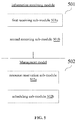
- FIG. 5 is a block diagram of a communication resource management device shown according to some examples of the present disclosure. As shown in FIG. 5 , this communication resource management device can be implemented as all or part of the access network device in the implementation environment shown in FIG. 1 by hardware or a combination of software and hardware.
- the communication resource management device can include:
- the latency indication information includes:
- the information receiving module 501 includes a first receiving sub-module 501a and/or a second receiving sub-module 501b.
- the first receiving sub-module 501a is configured to receive the latency indication information from the terminal by a radio resource control (RRC) message; and the second receiving sub-module 501b is configured to receive the latency indication information from the terminal by an uplink control signal.
- RRC radio resource control
- the RRC message is a UE capability information message.
- the uplink control signal is a control signal carried by a physical uplink control channel (PUCCH).
- PUCCH physical uplink control channel
- the management module 502 includes: a resource reservation sub-module 502a for reserving communication resources for the terminal according to the latency indication information.
- the resource reservation sub-module 502a is configured to reserve hybrid automatic repeat request (HARQ) resources for the terminal according to the latency indication information.
- HARQ hybrid automatic repeat request
- the resource reservation sub-module 502a is specifically configured to reserve, according to the latency indication information, uplink resources for the terminal for feeding back an acknowledgement/non-acknowledgement message; and the number of the uplink resources is inversely proportional to the latency indicated by the latency indication information.
- the management module 502 includes: a scheduling sub-module 502b for scheduling, according to the latency indication information, uplink and downlink transmission resources for the terminal.
- the access network device since the terminal reports its latency indication information to the access network device, and the access network device manages, for example, reserves or schedules communication resources of the terminal according to the processing latency of the terminal to the signal which is indicated by the latency indication information, the purpose of managing the communication resources of the terminal according to different processing latencies is achieved.
- FIG. 6 is a block diagram of a communication resource management device shown according to some examples. As shown in FIG. 6 , this communication resource management device can be implemented as all or part of the terminal in the implementation environment shown in FIG. 1 through hardware or a combination of software and hardware.
- the communication resource management device can include:
- the information reporting module 602 includes a first reporting sub-module 602a and/or a second reporting sub-module 602b.
- the first reporting sub-module 602a is configured to report the latency indication information to the access network device by a radio resource control (RRC) message; and the second reporting sub-module 602b is configured to report the latency indication information to the access network device by an uplink control signal.
- RRC radio resource control
- the terminal since the terminal reports its latency indication information to the access network device and the access network device manages communication resources of the terminal according to the processing latency of the terminal to the signal which is indicated by the latency indication information, the purpose of managing the communication resources of the terminal according to different processing latencies is achieved.
- Examples of the present disclosure also provide a communication resource management system.
- the system includes an access network device and at least one terminal.
- the access network device includes the communication resource management device as shown in FIG. 5 .
- the terminal includes the communication resource management device as shown in FIG. 6 .
- the device provided in the above examples is only illustrated by dividing the same into various functional modules.
- the above functions can be assigned to be completed by different functional modules according to actual needs, that is, the content structure of the device is divided into different functional modules to complete all or part of the functions described above.
- Examples of the present disclosure provides a communication resource management device capable of implementing the communication resource management method executed by the access network device in FIG. 2 or FIG. 3 of the present disclosure.
- the communication resource management device includes a processor and a memory for storing a processor-executable instruction.
- the processor is configured to:
- the latency indication information includes: an upper limit value of a processing capability of the terminal or a lower limit value of the latency for processing the signal by the terminal; and/or a current processing capability value of the terminal, latency for currently processing the signal by the terminal or an offset between the latency for currently processing the signal by the terminal and the lower limit value of the latency for processing the signal by the terminal.
- the receive the latency indication information of the terminal reported by the terminal including: receive the latency indication information from the terminal by a radio resource control (RRC) message; and/or receive the latency indication information from the terminal by an uplink control signal.
- RRC radio resource control
- the RRC message is a UE capability information message.
- the uplink control signal is control signal carried in a physical uplink control channel (PUCCH).
- PUCCH physical uplink control channel
- the manage communication resources of the terminal according to the latency indication information including: reserve communication resources for the terminal according to the latency indication information.
- the reserve communication resources for the terminal according to the latency indication information including: reserve hybrid automatic repeat request (HARQ) resources for the terminal according to the latency indication information.
- HARQ hybrid automatic repeat request
- the reserve hybrid automatic repeat request (HARQ) resources for the terminal according to the latency indication information including: reserve, according to the latency indication information, uplink resources for the terminal for feeding back an acknowledgement/non-acknowledgement message, wherein the number of the uplink resources is inversely proportional to the latency indicated by the latency indication information.
- HARQ hybrid automatic repeat request
- the manage communication resources of the terminal according to the latency indication information including: schedule, according to the latency indication information, uplink and downlink transmission resources for the terminal.
- Examples of the present disclosure provide a communication resource management device capable of implementing the communication resource management method executed by the terminal in FIG. 2 or FIG. 3 of the present disclosure.
- the communication resource management device includes a processor and a memory for storing a processor-executable instruction.
- the processor is configured to:
- the report the latency indication information to an access network device including: transmit the latency indication information to the access network device by a radio resource control (RRC) message; and/or transmit the latency indication information to the access network device by an uplink control signal.
- RRC radio resource control
- the communication resource management device includes corresponding hardware structures and/or software modules for executing various functions.
- Various modules and algorithm steps described in conjunction with the examples disclosed in the present disclosure may be implemented as hardware or a combination of hardware and computer software. Whether certain function is implemented in the manner of hardware or in the manner that computer software drives the hardware depends on particular applications and design constraints of the technical solutions. A person skilled in the art may implement the described functions with different methods for each of particular applications, but such implementation shall not be regarded as going beyond the scope of the technical solution of the embodiment of the present disclosure.
- FIG. 7 is a structural diagram of a communication device according to some embodiments of the present disclosure.
- the communication device can be implemented as the access network device or the terminal in the system shown in FIG. 1 .
- the communication device 700 includes an antenna 701, a processor 702 and a communication interface 705.
- the processor 702 can also be a controller and is represented as a "controller/processor 702" in FIG. 7 .
- the antenna 701 is configured to support transceiving of information between the communication device and the terminal in the above examples.
- the processor 702 executes various functions for communicating with the terminal.
- On an uplink an uplink signal from the terminal is received through the antenna 701, further processed by the processor 702, and sent to the central unit through the communication interface 705.
- protocol data that is received through the communication interface 705 and sent by the central unit is processed by the processor 702, and then transmitted to the terminal through the antenna 701.
- the communication device 700 can include a memory 703 for storing a program code and data of the communication device 700.
- FIG. 7 only shows simplified design of the communication device 700.
- the communication device 700 can include any number of transmitters, receivers, processors, controllers, memories, communication units and the like, and all communication devices that can implement the embodiments of the present disclosure are within the scope of protection of the examples of the present disclosure.
- the functions described in the embodiments of the present disclosure can be implemented in hardware, software, firmware, or any combination thereof. If the functions are implemented in the software, they can be stored in a computer-readable medium or transmitted as one or more instructions or codes on a computer-readable medium, such as a non-transitory computer-readable storage medium.
- the non-transitory computer-readable medium can include a computer storage medium and a communication medium, wherein the communication medium includes any medium that facilitates transfer of a computer program from one place to another, and the storage medium can be any available medium that can be accessed by a general-purpose or special-purpose computer.
- Embodiments of the present disclosure further provide a computer storage medium which is used for storing a computer software instruction used by the above communication device and contains a program designed for executing method steps corresponding to the access network device or the terminal in FIG. 2 or FIG. 3 .
- the storage medium or memory can be implemented by any type of volatile or non-volatile storage devices or combinations thereof, such as a static anytime access memory (SRAM), an electrically erasable programmable read-only memory (EEPROM), an erasable programmable read-only memory (EPROM), a programmable read-only memory (PROM), a read-only memory (ROM), a magnetic memory, a flash memory, a disk or a CD.
- SRAM static anytime access memory
- EEPROM electrically erasable programmable read-only memory
- EPROM erasable programmable read-only memory
- PROM programmable read-only memory
- ROM read-only memory
Landscapes
- Engineering & Computer Science (AREA)
- Signal Processing (AREA)
- Computer Networks & Wireless Communication (AREA)
- Quality & Reliability (AREA)
- Databases & Information Systems (AREA)
- Mobile Radio Communication Systems (AREA)
Abstract
Description
- The present disclosure relates to the field of radio communication technology, and in particular, to a communication resource management method, device and system.
- In radio communications, there is usually a time interval between the time that a terminal receives a signal from an antenna and the time that the terminal obtains content of the signal by decoding the signal. The time interval may be referred to as a processing latency for processing the signal by the terminal.
- The processing latency for processing the signal is one of factors that should be considered when an access network device manages radio communication resources of the terminal. In a long term evolution (LTE) system, each terminal has the processing latency of 4 subframes by default, i.e., 4ms. That is, for all terminals access to the access network device, the access network device manages radio resources of each terminal according to the processing latency of 4 subframes.
- Various embodiments of the present disclosure provides a communication resource management method. The technical solutions are as follows.
- According to a first aspect of the present disclosure, there is provided a communication resource management method. The method includes:
- a terminal transmitting latency indication information of the terminal to an access network device, wherein the latency indication information is configured to indicate latency for processing a signal by the terminal; and
- managing communication resources of the terminal according to the latency indication information.
- According to a second aspect of the present disclosure, there is provided a communication resource management method. The method includes:
- receiving latency indication information of a terminal from the terminal, wherein the latency indication information is configured to indicate latency for processing a signal by the terminal; and
- managing communication resources of the terminal according to the latency indication information.
- In some embodiments, the latency indication information comprises:
- an upper limit value of a processing capability of the terminal or a lower limit value of the latency for processing the signal by the terminal, and/or
- a current processing capability value of the terminal, latency for currently processing the signal by the terminal or an offset between the latency for currently processing the signal by the terminal and the lower limit value of the latency for processing the signal by the terminal.
- In some embodiments, receiving latency indication information of a terminal from the terminal comprises:
- receiving the latency indication information reported by the terminal through a radio resource control (RRC) message; and/or
- receiving the latency indication information reported by the terminal through an uplink control signal.
- In some embodiments, the RRC message is a UE capability information message.
- In some embodiments, the uplink control signal is a control signal carried by a physical uplink control channel (PUCCH).
- In some embodiments, managing communication resources of the terminal according to the latency indication information comprises:
reserving communication resources for the terminal according to the latency indication information. - In some embodiments, reserving communication resources for the terminal according to the latency indication information comprises:
reserving hybrid automatic repeat request (HARQ) resources for the terminal according to the latency indication information. - In some embodiments, reserving HARQ resources for the terminal according to the latency indication information comprises:
reserving, according to the latency indication information, uplink resources for the terminal for feeding back an acknowledgement/non-acknowledgement message; and the number of the uplink resources is inversely proportional to the latency indicated by the latency indication information. - In some embodiments, managing communication resources of the terminal according to the latency indication information includes:
scheduling, according to the latency indication information, uplink and downlink transmission resources for the terminal. - According to a third aspect of the present disclosure, there is provided a communication resource management method, including:
- acquiring latency indication information of a terminal, wherein the latency indication information is configured to indicate latency for processing a signal by the terminal; and
- transmitting the latency indication information to an access network device, so that the access network device manages communication resources of the terminal according to the latency indication information.
- In some embodiments, the latency indication information includes:
- an upper limit value of a processing capability of the terminal or a lower limit value of the latency for processing the signal by the terminal, and/or
- a current processing capability value of the terminal, latency for currently processing the signal by the terminal, or an offset between the latency for currently processing the signal by the terminal and the lower limit value of the latency for processing the signal by the terminal.
- According to a fourth aspect of the present disclosure, there is provided a communication resource management device, including:
- an information acquisition module, configured to acquire latency indication information of a terminal, wherein the latency indication information is configured to indicate latency for processing a signal by the terminal; and
- an information reporting module, configured to transmit the latency indication information to an access network device, so that the access network device manages communication resources of the terminal according to the latency indication information.
- In some embodiments, the information receiving module includes a first receiving sub-module and/or a second receiving sub-module;
the first receiving sub-module is configured to receive the latency indication information from the terminal by a radio resource control (RRC) message; and
the second receiving sub-module is configured to receive the latency indication information from the terminal by an uplink control signal. - In some embodiments, the RRC message is a UE capability information message.
- In some embodiments, the uplink control signal is a control signal carried by a physical uplink control channel (PUCCH).
- In some embodiments, the management module includes:
a resource reservation sub-module, configured to reserve communication resources for the terminal according to the latency indication information. - In some embodiments, the resource reservation sub-module is configured to reserve hybrid automatic repeat request (HARQ) resources for the terminal according to the latency indication information.
- In some embodiments, the resource reservation sub-module is further configured to reserve, according to the latency indication information, uplink resources for the terminal for feeding back an acknowledgement/non-acknowledgement message; and the resource amount of the uplink resources is inversely proportional to the latency indicated by the latency indication information.
- In some embodiments, the management module includes:
a scheduling sub-module, configured to schedule, according to the latency indication information, uplink and downlink transmission resources used by the terminal. - According to a fifth aspect of the present disclosure, there is provided a communication resource management device. The device includes:
- an information acquisition module, configured to acquire latency indication information of a terminal, wherein the latency indication information is used to indicate latency for processing a signal by the terminal; and
- an information reporting module, configured to report the latency indication information to an access network device, so that the access network device manages communication resources of the terminal according to the latency indication information.
- In some embodiments, the information reporting module includes: a first reporting sub-model and/or a second reporting sub-model;
the first reporting sub-module, configured to transmit the latency indication information to the access network device by a radio resource control (RRC) message; and
the second reporting sub-module, configured to transmit the latency indication information to the access network device by an uplink control signal. - According to a sixth aspect of the present disclosure, there is provided a communication resource management system. The system includes an access network device and a terminal.
- The access network device includes the communication resource management device shown in the fourth aspect or any optional implementation mode of the fourth aspect.
- The terminal includes the communication resource management device shown in the fifth aspect or any optional implementation mode of the fifth aspect.
- According to a seventh aspect of the present disclosure, there is provided a communication resource management device, communication resource management device, including:
- a processor; and
- a memory for storing a processor-executable instruction, wherein
- the processor is configured to:
- receive latency indication information of a terminal from the terminal, wherein the latency indication information is configured to indicate latency for processing a signal by the terminal; and
- manage communication resources of the terminal according to the latency indication information.
- According to an eighth aspect of the present disclosure, there is provided a communication resource management device, communication resource management device, including:
- a processor; and
- a memory for storing a processor-executable instruction, wherein
- the processor is configured to:
- acquire latency indication information of a terminal, wherein the latency indication information is configured to indicate latency for processing a signal by the terminal; and
- transmit the latency indication information to an access network device, so that the access network device manages communication resources of the terminal according to the latency indication information.
- The technical solution provided in examples of the present disclosure may lead the following beneficial effects.
- Since the terminal reports its latency indication information to the access network device, and the access network device manages communication resources of the terminal according to the latency indication information, the purpose of managing the communication resources of the terminal according to different processing latencies is achieved.
- It is to be understood that both the foregoing general description and the following detailed description are examples and are not intended to limit the present disclosure.
- The accompanying drawings referred to in the specification are a part of this disclosure, and provide illustrative embodiments consistent with the disclosure and, together with the detailed description, serve to illustrate some embodiments of the disclosure.
-
FIG. 1 is a structural diagram of a mobile communication system according to some embodiments t of the present disclosure; -
FIG. 2 is a flowchart of a communication resource management method according to some embodiments of the present disclosure; -
FIG. 3 is a flowchart of a communication resource management method according to some embodiments of the present disclosure; -
FIG. 4 is a diagram of resource reservation involved in examples shown inFIG. 3 ; -
FIG. 5 is a block diagram of a communication resource management device according to some embodiments; -
FIG. 6 is a block diagram of a communication resource management device according to some embodiments; and -
FIG. 7 is a block diagram of a communication device according to some embodiments. - Reference will now be made in detail to embodiments, examples of which are illustrated in the accompanying drawings. The following description refers to the accompanying drawings in which the same numbers in different drawings represent the same or similar elements unless otherwise represented. The implementations set forth in the following description of embodiments do not represent all implementations consistent with the present disclosure. Instead, they are merely examples of devices and methods consistent with aspects related to the invention/disclosure as recited in the appended claims.
- It should be understood that "a plurality" as referred to herein means one or more, "many" as referred to herein means two or more. "And/or" describes an association relationship between associated objects and indicates that there may be three relationships. For example, A and/or B may indicate that there are three cases where A exists separately, A and B exist at the same time, and B exists separately. The character "/" generally indicates that an "or" relationship exists between contextual objects.
-
FIG. 1 is a structural diagram of a mobile communication system shown according to some examples of the present disclosure. This mobile communication system can be a 5G (the 5th generation mobile communication) system, also called an NR (new radio) system. The mobile communication system includes anaccess network device 120 and a terminal 140. - The
access network device 120 can be a base station. For example, the base station can be a base station (gNB) that adopts centralized and distributed architecture in the 5G system. When adopting the centralized and distributed architecture, theaccess network device 120 generally includes a central unit (CU) and at least two distributed units (DU). A protocol stack includes a packet data convergence protocol (PDCP) layer, a radio link control (RLC) layer and a media access control (MAC) layer is set in the central unit, a physical (PHY) layer protocol stack is set in the distributed unit, and the specific implementation mode of theaccess network device 120 is not limited in examples of the present disclosure. - The
access network device 120 establishes a radio connection with the terminal 140 through a radio air interface. In some embodiments, the radio air interface is a radio air interface based on a 5G standard. For example, the radio air interface is a new radio (NR) air interface. - Alternatively, the radio air interface can also be a radio air interface based on a next generation mobile communication network technology standard of 5G.
- The terminal 140 can be a device that provides voice and/or data connectivity for users. The terminal, also called user equipment (UE), can communicate with one or more core networks via a radio access network (RAN). The terminal 140 can be a mobile terminal, such as a mobile phone (or referred to as a "cell" phone), and a computer having a mobile terminal, which for example can be a portable, pocket-sized, handheld, computer-embedded, or vehicle-mounted mobile device, such as a subscriber unit, a subscriber station, a mobile station, a mobile platform, a remote station, an access point, a remote terminal, an access terminal, a user terminal, a user agent, a user device or user equipment.
- It should be noted that the mobile communication system shown in
FIG. 1 can include a plurality ofaccess network devices 120 and/or a plurality ofterminals 140.FIG. 1 illustrates the mobile communication system including oneaccess network devices 120 and oneterminal 140. This is not limited in the embodiment of the present disclosure. - The current service types of the 5G system include eMBB (enhanced mobile broad band), mMTC (massive machine type communication), URLLC (ultra-reliable low-latency communication) and the like, and there can be more segmentation types in the future. All those services belong to data services, but have different requirements on latency and reliability. For example, the URLLC service can be applied to scenarios, for example, the Internet of vehicles, which request low latency and high timeliness and can be pre-emption for prior services. The mMTC service generally is insensitive to latency and can deliver data after a long-time interval.
- In order to meet demands of low-latency of the URLLC service and the like, the terminal is required to reduce the processing latency for processing a signal. In the 5G system, the processing latency of the terminal is affected by many factors, such as the process capability of a baseband processor, the power consumption condition of the terminal, the cost of the terminal, and a specific form of the terminal (a mobile phone, a wearable device, an Internet-of-things device, MiFi and other dedicated devices). Therefore, the processing latency of different terminals for the signal can be different, and even if it is the same terminal, the processing latency thereof for the signal can be different under different working states. For example, in the LTE system, the processing latency of the terminal is T+4 (ms), while in the 5G system, some terminals can achieve the processing latency of T+3 (ms), and some terminals with higher capability can achieve the processing latency of T+2 (ms), T+1 (ms) and even T+0(ms).
- Alternatively, certain terminal can achieve the processing latency of T+2 (ms) in a high-power state and can restore to the processing latency of T+4 (ms) under a lower-power state.
- To meet the demands of managing the communication resources of the terminal according to the different processing latencies in the 5G system, examples of the present disclosure provides a communication resource management solution. That is, the access network device manages communication resources of different terminals according to the processing latencies of the terminals. For example, the access network device reserves or schedules resources for a terminal according to the processing latency of the terminal. The details are shown in the following examples.
-
FIG. 2 is a flowchart of a communication resource management method shown according to some examples. As shown inFIG. 2 , the communication resource management method is applied to the implementation environment shown inFIG. 1 and can include the following steps. - In step 201, a terminal reports latency indication information of the terminal to an access network device, wherein the latency indication information is configured to indicate latency for processing a signal by the terminal.
- In
step 202, the access network device receives the latency indication information of the terminal from the terminal. - In
step 203, the access network device manages communication resources of the terminal according to the latency indication information. - In some embodiments, the latency indication information includes: a upper limit value of a processing capability of the terminal or a lower limit value of the processing latency for processing the signal by the terminal, and/or a current processing capability value of the terminal, a processing latency for processing the signal by the terminal, or an offset between the latency for currently processing the signal by the terminal and the lower limit value of the latency for processing the signal by the terminal.
- In some embodiments, the access network device receives the latency indication information of the terminal from the terminal, including:
the access network device receives the latency indication information from the terminal through a radio resource control (RRC) message; and/or the access network device receives the latency indication information from the terminal through an uplink control signal. - In some embodiments, the RRC message is a UE capability information message.
- In some embodiments, the uplink control signal is control signal carried by a physical uplink control channel (PUCCH).
- In some embodiments, the access network device manages communication resources of the terminal according to the latency indication information, including: the access network device reserves communication resources for the terminal according to the latency indication information.
- In some embodiments, the access network device reserves communication resources for the terminal according to the latency indication information includes: the access network device reserves hybrid automatic repeat request (HARQ) resources for the terminal according to the latency indication information.
- In some embodiments, the access network device reserves HARQ resources for the terminal according to the latency indication information includes: the access network device reserves, according to the latency indication information, uplink resources for the terminal for feeding back an acknowledgement/non-acknowledgement message; and the number of the uplink resources is inversely proportional to the latency indicated by the latency indication information.
- In some embodiments, the access network device manages communication resources of the terminal according to the latency indication information includes: the access network device schedules, according to the latency indication information, uplink and downlink transmission resources for the terminal.
- Therefore, for the communication resource management method shown in some examples of the present disclosure, since the terminal reports its latency indication information to the access network device, and the access network device manages communication resources of the terminal according to the latency indication information, so as to the purpose of managing the communication resources of the terminal according to different processing latencies is achieved.
-
FIG. 3 is a flowchart of a communication resource management method according to some embodiments of the present disclosure. As shown inFIG. 3 , the communication resource management method is applied to the implementation environment shown inFIG. 1 and can include the following steps. - In step 301, a terminal acquires latency indication information of the terminal, wherein the latency indication information is configured to indicate latency for processing a signal by the terminal.
- In examples of the present disclosure, the latency for processing the signal by the terminal is mainly latency for receiving and demodulating data by a baseband processor of the terminal.
- In some embodiments, the latency indication information includes: a upper limit value of a processing capability of the terminal or a lower limit value of the processing latency for processing the signal by the terminal, and/or a current processing capability value of the terminal, a processing latency for processing the signal by the terminal, or an offset between the latency for currently processing the signal by the terminal and the lower limit value of the latency for processing the signal by the terminal.
- In examples of the present disclosure, the processing capability value of the terminal can be defined by a new UE capability category information of a radio communication system, and different processing capability values correspond to different processing latencies (in some literatures or materials, the processing latency is also known as a scheduling granularity). For example, table 1 shows a corresponding relationship related to examples of the present disclosure between the processing capability value and the processing latency.
Table 1 Processing Capability Value Processing Latency t 1 t1 2 t2 3 t3 4 t4 - As shown in table 1, processing capability values of the terminal are divided into four levels, i.e.,
level 1,level 2, level 3 and level 4. The terminal having the processing capability value of 1 has the processing latency of t1 for processing the signal, and accordingly the terminal having the processing capability value of 2 has the processing latency of t2 for processing the signal, and so on. - When the terminal acquires the latency indication information, the terminal can directly acquire the lower limit value of the latency for processing the signal by the terminal (i.e., the lowest latency for processing the signal by the terminal). For example, if the lowest latency for processing the signal by the terminal is t2, the latency indication information acquired by the terminal is t2.
- Alternatively, when the terminal acquires the latency indication information, the terminal can also acquire the lower limit value of the latency for processing the signal by the terminal, and searches for a corresponding processing capability value according to the lower limit value of the latency, then determines the corresponding processing capability value as the upper limit value of the processing capability of terminal. And the terminal determines the upper limit value of the processing capability as the latency indication information.
- In addition, some terminals have a variable processing latency for processing a signal. For example, the same terminal can have different processing latencies for processing the signal in high power situation and in lower power situation. Therefore, in the manner shown in examples of the present disclosure, the latency indication information can be the current processing capability value of the terminal, the processing latency for processing the signal by the terminal, or an offset between the latency for currently processing the signal by the terminal and the lower limit value of the latency for processing the signal by the terminal.
- For example, when the terminal acquires the latency indication information, the terminal can directly acquire the latency for currently processing the signal by the terminal. For example, if the latency for currently processing the signal by the terminal is t2, the latency indication information acquired by the terminal is t2.
- Alternatively, when the terminal acquires the latency indication information, the terminal can also acquire the latency for currently processing the signal by the terminal, and searches for a corresponding processing capability value according to the latency. The corresponding processing capability value is the current processing capability value of the terminal, and the terminal determines the current processing capability value as the latency indication information.
- Alternatively, in another implementation, the terminal can also acquire the lower limit value of the latency for processing the signal by the terminal and the latency for currently processing the signal by the terminal, and determines the offset between the latency for currently processing the signal by the terminal and the lower limit value of the latency for processing the signal by the terminal as the latency indication information.
- The latency indication information acquired by the terminal may only indicate the lower limit value of the processing latency of the terminal, that is, the latency indication information includes the upper limit value of the processing capability of the terminal or the lower limit value of the latency for processing the signal by the terminal.
- Alternatively, the latency indication information acquired by the terminal may only indicate the current processing latency of the terminal, that is, the latency indication information includes the current processing capability value of the terminal, the latency for currently processing the signal by the terminal, or the offset between the latency for currently processing the signal by the terminal and the lower limit value of the latency for processing the signal by the terminal.
- Alternatively, the latency indication information acquired by the terminal may simultaneously indicate the lowest processing latency and the current processing latency of the terminal, that is, the latency indication information contains the upper limit value of the processing capability of the terminal or the lower limit value of the latency for processing the signal by the terminal, the current processing capability value of the terminal, the latency for currently processing the signal by the terminal, or the offset between the latency for currently processing the signal by the terminal and the lower limit value of the latency for processing the signal by the terminal.
- In step 302, the terminal reports the latency indication information of the terminal to the access network device.
- In some embodiments, the terminal can report the latency indication information to the access network device through a radio resource control (RRC) message; and/or report the latency indication information to the access network device through an uplink control signal.
- In some implementations, the terminal can report the latency e indication information to the access network device through the RRC message in a network attachment procedure. For example, in the network attachment procedure, the terminal can report, through the RRC message, to the access network device, the upper limit value of the processing capability of the terminal or the lower limit value of the latency for processing the signal by the terminal. Of course, the terminal can report the latency indication information to the access network device by the RRC message, such as the current processing capability value of the terminal, the latency for currently processing the signal by the terminal or the offset between the latency for currently processing the signal by the terminal and the lower limit value of the latency for processing the signal by the terminal.
- In some embodiments, the RRC message is a UE capability information message.
- There can be many different types of RRC messages sent to the access network device by the terminal. In examples of the present disclosure, the terminal can report the latency indication information to the access network device through the UE capability information message in the RRC messages. For example, the terminal can add a new field to the release field of the UE capability information message. For example, the newly-added field can be named a UE process time field, and is configured to carry the latency indication information mentioned above.
- In another implementation, after completion of connection establishment with the access network device, the terminal can report the latency indication information to the access network device through the uplink control signal. For example, after completion of the connection establishment, the terminal can report, through the uplink control signal, to the access network device, the latency indication information, such as the current processing capability value of the terminal, the latency for currently processing the signal by the terminal, or the offset between the latency for currently processing the signal by the terminal and the lower limit value of the latency for processing the signal by the terminal. Of course, the terminal can also report the upper limit value of the processing capability of the terminal or the lower limit value of the latency for processing the signal through the uplink control signal.
- In some embodiments, the uplink control signal is a control signal carried in a physical uplink control channel (PUCCH).
- In
step 303, the access network device receives the latency indication information of the terminal from the terminal. - Accordingly, the access network device can receive the latency indication information reported by the terminal through the RRC message; and/or receive the latency indication information reported by the terminal through the uplink control signal.
- In
step 304, the access network device manages communication resources of the terminal according to the latency indication information. - In some examples of the present disclosure, the access network device can reserve communication resources for the terminal according to the latency indication information.
- In some embodiments, when the access network device reserves communication resources for the terminal according to the latency indication information, the access network device can reserve hybrid automatic repeat request (HARQ) resources for the terminal according to the latency indication information. For example, the access network device can reserve, according to the latency indication information, uplink resources for the terminal for feeding back an acknowledgement/non-acknowledgement (ACK/NACK) message; and the number of the uplink resources is inversely proportional to the latency indicated by the latency indication information.
-
FIG. 4 shows a diagram of resource reservation involved in examples of the present disclosure.FIG. 4 indicates a comparison between relations of each resource reservation condition and the corresponding latency indication information, by taking reservation of ACK/NACK resources for the terminal according to the latency indication information as an example. It is assumed that one subframe includes 13 time-domain resource units that can be used for uplink and downlink data transmission. Each rectangular grid inFIG. 4 represents one time-domain resource unit, for example, an orthogonal frequency division multiplexing (OFDM) symbol. - In part (a) of
FIG. 4 , T+0 represents that the latency indication information of the terminal indicates that the lower limit value of the processing latency or the current processing latency of the terminal is within a time range of one subframe (that is, 1ms). That is, for the downlink data sent to the terminal in one subframe, the terminal can finish the processing and feed back the ACK/NACK message within the current subframe. At this time, the access network device can reserve, for the terminal, uplink resources in each subframe for feeding back the ACK/NACK message. For example, as shown in part (a) ofFIG. 4 , the access network device reserves the first 10 time-domain resource units of the 13 time-domain resource units, which can be used for uplink and downlink data transmission in each ofsubframe 1 andsubframe 2, as the downlink time-domain resource units corresponding to the terminal, and reserves the last 3 time-domain resource units as the uplink time-domain resource units for the terminal. - In part (b) of
FIG. 4 , T+1 represents that the latency indication information of the terminal indicates that the lower limit value of the processing latency or the current processing latency of the terminal is within a time range between one subframe and two subframe, (that is, 1ms∼2ms). That is, for the downlink data sent to the terminal in one subframe, the terminal can complete the processing and feed back the ACK/NACK message within a subframe next to the current subframe. At this time, the access network device can reserve uplink resources for feeding back the ACK/NACK message every other subframe. For example, as shown in part (b) ofFIG. 4 , for two continues subframes (subframe 3 and subframe 4), the access network device reserves all 13 time-domain resource units in subframe 3 and the first 10 time-domain resource units in subframe 4, which can be used for uplink and downlink data transmission, as the downlink time-domain resource units for the terminal, and reserves the last 3 time-domain resource units in subframe 4 as the uplink time-domain resource units for the terminal. - In some embodiments, the access network device can schedule, according to the latency indication information, uplink and downlink transmission resources for the terminal.
- For example, referring to
FIG. 4 , for the terminal having the processing latency corresponding to T+0, when access network device sends data to the terminal, the access network device can instruct the terminal to receive the data from the access network device on the first time-domain resource unit (that is, the time-domain resource unit 4a-1 inFIG. 4 ) insubframe 1 shown inFIG. 4 , and instruct the terminal to report the ACK/NACK message, for the data received on the timedomain resource unit 4a-1, on the eleventh time-domain resource unit (that is, the time-domain resource unit 4a-2 inFIG. 4 ). Accordingly, for the terminal having the processing latency corresponding to T+1, when the access network device sends data to the terminal, the access network device can instruct the terminal to receive the data from the access network device on the first time-domain resource unit (i.e., the time-domain resource unit 4b-1 inFIG. 4 ) in subframe 3 shown inFIG. 4 , and instruct the terminal to report the ACK/NACK message on the eleventh time-domain resource unit (that is, the time-domain resource unit 4b-2 inFIG. 4 ) for the data received on the timedomain resource unit 4b-1. - It should be noted that in the examples shown in
FIG. 4 , the uplink and downlink time-domain resource units reserved for the terminal by the access network device can be specific time-domain resource units for the terminal. - Alternatively, the uplink and downlink time-domain resource units reserved for the terminal by the access network device can be time-frequency resource units shared by the terminal and other terminals, that is, in the uplink and downlink time-frequency resource units, if the terminal is not scheduled to occupy these time-domain resource units, the access network device can instruct, by a scheduling message, other terminals to occupy the above time-domain resource units.
- Therefore, for the communication resource management method shown in examples of the present disclosure, since the terminal reports its latency indication information to the access network device, and the access network device manages, for example, reserves or schedules communication resources of the terminal according to the processing latency of the terminal to the signal which is indicated by the latency indication information, the purpose of managing the communication resources of the terminal according to different processing latencies can be achieved.
- The following is examples of devices, which can be adopted to implement some examples of methods of the present disclosure. For the details not disclosed in the examples of the devices of the present disclosure, reference can be made to the examples of methods of the present disclosure.
-
FIG. 5 is a block diagram of a communication resource management device shown according to some examples of the present disclosure. As shown inFIG. 5 , this communication resource management device can be implemented as all or part of the access network device in the implementation environment shown inFIG. 1 by hardware or a combination of software and hardware. The communication resource management device can include: - an
information receiving module 501, configured to receive latency indication information of a terminal reported by the terminal, wherein the latency indication information is configured to indicate latency for processing a signal by the terminal; and - a
management module 502, configured to manage communication resources of the terminal according to the latency indication information. - In some embodiments, the latency indication information includes:
- an upper limit value of a processing capability of the terminal or a lower limit value of the latency for processing the signal by the terminal, and/or
- a current processing capability value of the terminal, the latency for currently processing the signal by the terminal, or an offset between the latency for currently processing the signal by the terminal and the lower limit value of the latency for processing the signal by the terminal.
- In some embodiments, the
information receiving module 501 includes a first receiving sub-module 501a and/or a second receiving sub-module 501b. - The first receiving sub-module 501a is configured to receive the latency indication information from the terminal by a radio resource control (RRC) message; and
the second receiving sub-module 501b is configured to receive the latency indication information from the terminal by an uplink control signal. - In some embodiments, the RRC message is a UE capability information message.
- In some embodiments, the uplink control signal is a control signal carried by a physical uplink control channel (PUCCH).
- In some embodiments, the
management module 502 includes:
aresource reservation sub-module 502a for reserving communication resources for the terminal according to the latency indication information. - In some embodiments, the
resource reservation sub-module 502a is configured to reserve hybrid automatic repeat request (HARQ) resources for the terminal according to the latency indication information. - In some embodiments, the
resource reservation sub-module 502a is specifically configured to reserve, according to the latency indication information, uplink resources for the terminal for feeding back an acknowledgement/non-acknowledgement message; and the number of the uplink resources is inversely proportional to the latency indicated by the latency indication information. - In some embodiments, the
management module 502 includes: a scheduling sub-module 502b for scheduling, according to the latency indication information, uplink and downlink transmission resources for the terminal. - Therefore, for the communication resource management device shown in examples of the present disclosure, since the terminal reports its latency indication information to the access network device, and the access network device manages, for example, reserves or schedules communication resources of the terminal according to the processing latency of the terminal to the signal which is indicated by the latency indication information, the purpose of managing the communication resources of the terminal according to different processing latencies is achieved.
-
FIG. 6 is a block diagram of a communication resource management device shown according to some examples. As shown inFIG. 6 , this communication resource management device can be implemented as all or part of the terminal in the implementation environment shown inFIG. 1 through hardware or a combination of software and hardware. The communication resource management device can include: - an
information acquisition module 601 for acquiring latency indication information of a terminal, wherein the latency indication information is used to indicate latency for processing a signal by the terminal; and - an
information reporting module 602 for reporting the latency indication information to an access network device, so that the access network device manages communication resources of the terminal according to the latency indication information. - In some embodiments, the
information reporting module 602 includes afirst reporting sub-module 602a and/or asecond reporting sub-module 602b. - The
first reporting sub-module 602a is configured to report the latency indication information to the access network device by a radio resource control (RRC) message; and
thesecond reporting sub-module 602b is configured to report the latency indication information to the access network device by an uplink control signal. - Therefore, for the communication resource management device shown in the embodiments of the present disclosure, since the terminal reports its latency indication information to the access network device and the access network device manages communication resources of the terminal according to the processing latency of the terminal to the signal which is indicated by the latency indication information, the purpose of managing the communication resources of the terminal according to different processing latencies is achieved.
- Examples of the present disclosure also provide a communication resource management system. The system includes an access network device and at least one terminal.
- The access network device includes the communication resource management device as shown in
FIG. 5 . - The terminal includes the communication resource management device as shown in
FIG. 6 . - It should be noted that when implementing its function, the device provided in the above examples is only illustrated by dividing the same into various functional modules. In practical application, the above functions can be assigned to be completed by different functional modules according to actual needs, that is, the content structure of the device is divided into different functional modules to complete all or part of the functions described above.
- For the device in the above examples, the specific mode of each module for executing operations has been described in details in the embodiment of the related method and is not further described in detail herein.
- Examples of the present disclosure provides a communication resource management device capable of implementing the communication resource management method executed by the access network device in
FIG. 2 orFIG. 3 of the present disclosure. The communication resource management device includes a processor and a memory for storing a processor-executable instruction. - The processor is configured to:
- receive latency indication information of a terminal from the terminal, wherein the latency indication information is configured to indicate latency for processing a signal by the terminal; and
- manage communication resources of the terminal according to the latency indication information.
- In some embodiments, the latency indication information includes: an upper limit value of a processing capability of the terminal or a lower limit value of the latency for processing the signal by the terminal; and/or a current processing capability value of the terminal, latency for currently processing the signal by the terminal or an offset between the latency for currently processing the signal by the terminal and the lower limit value of the latency for processing the signal by the terminal.
- In some embodiments, the receive the latency indication information of the terminal reported by the terminal, including:
receive the latency indication information from the terminal by a radio resource control (RRC) message; and/or receive the latency indication information from the terminal by an uplink control signal. - In some embodiments, the RRC message is a UE capability information message.
- In some embodiments, the uplink control signal is control signal carried in a physical uplink control channel (PUCCH).
- In some embodiments, the manage communication resources of the terminal according to the latency indication information, including: reserve communication resources for the terminal according to the latency indication information.
- In some embodiments, the reserve communication resources for the terminal according to the latency indication information, including:
reserve hybrid automatic repeat request (HARQ) resources for the terminal according to the latency indication information. - In some embodiments, the reserve hybrid automatic repeat request (HARQ) resources for the terminal according to the latency indication information, including: reserve, according to the latency indication information, uplink resources for the terminal for feeding back an acknowledgement/non-acknowledgement message, wherein the number of the uplink resources is inversely proportional to the latency indicated by the latency indication information.
- In some embodiments, the manage communication resources of the terminal according to the latency indication information, including: schedule, according to the latency indication information, uplink and downlink transmission resources for the terminal.
- Examples of the present disclosure provide a communication resource management device capable of implementing the communication resource management method executed by the terminal in
FIG. 2 orFIG. 3 of the present disclosure. The communication resource management device includes a processor and a memory for storing a processor-executable instruction. - The processor is configured to:
- acquire latency indication information of a terminal, wherein the latency indication information is configured to indicate latency for processing a signal by the terminal; and
- transmit the latency indication information to an access network device, so that the access network device manages communication resources of the terminal according to the latency indication information.
- In some embodiments, the report the latency indication information to an access network device, including:
transmit the latency indication information to the access network device by a radio resource control (RRC) message; and/or transmit the latency indication information to the access network device by an uplink control signal. - The solution provided in some examples of the present disclosure is mainly described by taking the communication resource management device as an example. It may be understood that for implementing the above functions, the communication resource management device includes corresponding hardware structures and/or software modules for executing various functions. Various modules and algorithm steps described in conjunction with the examples disclosed in the present disclosure may be implemented as hardware or a combination of hardware and computer software. Whether certain function is implemented in the manner of hardware or in the manner that computer software drives the hardware depends on particular applications and design constraints of the technical solutions. A person skilled in the art may implement the described functions with different methods for each of particular applications, but such implementation shall not be regarded as going beyond the scope of the technical solution of the embodiment of the present disclosure.
-
FIG. 7 is a structural diagram of a communication device according to some embodiments of the present disclosure. The communication device can be implemented as the access network device or the terminal in the system shown inFIG. 1 . - The
communication device 700 includes anantenna 701, aprocessor 702 and acommunication interface 705. Theprocessor 702 can also be a controller and is represented as a "controller/processor 702" inFIG. 7 . Theantenna 701 is configured to support transceiving of information between the communication device and the terminal in the above examples. Theprocessor 702 executes various functions for communicating with the terminal. On an uplink, an uplink signal from the terminal is received through theantenna 701, further processed by theprocessor 702, and sent to the central unit through thecommunication interface 705. On a downlink, protocol data that is received through thecommunication interface 705 and sent by the central unit is processed by theprocessor 702, and then transmitted to the terminal through theantenna 701. - Further, the
communication device 700 can include amemory 703 for storing a program code and data of thecommunication device 700. - It can be understood that
FIG. 7 only shows simplified design of thecommunication device 700. In practical application, thecommunication device 700 can include any number of transmitters, receivers, processors, controllers, memories, communication units and the like, and all communication devices that can implement the embodiments of the present disclosure are within the scope of protection of the examples of the present disclosure. - A person skilled in the art shall appreciate that in one or more examples described above, the functions described in the embodiments of the present disclosure can be implemented in hardware, software, firmware, or any combination thereof. If the functions are implemented in the software, they can be stored in a computer-readable medium or transmitted as one or more instructions or codes on a computer-readable medium, such as a non-transitory computer-readable storage medium.
- The non-transitory computer-readable medium can include a computer storage medium and a communication medium, wherein the communication medium includes any medium that facilitates transfer of a computer program from one place to another, and the storage medium can be any available medium that can be accessed by a general-purpose or special-purpose computer.
- Embodiments of the present disclosure further provide a computer storage medium which is used for storing a computer software instruction used by the above communication device and contains a program designed for executing method steps corresponding to the access network device or the terminal in
FIG. 2 orFIG. 3 . - The storage medium or memory can be implemented by any type of volatile or non-volatile storage devices or combinations thereof, such as a static anytime access memory (SRAM), an electrically erasable programmable read-only memory (EEPROM), an erasable programmable read-only memory (EPROM), a programmable read-only memory (PROM), a read-only memory (ROM), a magnetic memory, a flash memory, a disk or a CD.
- Various embodiments of the present disclosure can have one or more of the following advantages.
- Other examples of the present disclosure will be apparent to those skilled in the art from consideration of the specification and practice of the present disclosure. This application is intended to cover any variations, uses, or adaptations of the disclosure following the general principles thereof and including such departures from the present disclosure as come within known or customary practice in the art. (It is intended that the specification and examples be considered as example only, with a true scope and spirit of the present disclosure being indicated by the following claims.
- It should be appreciated that the present disclosure is not limited to the exact construction that has been described above and illustrated in the accompanying drawings, and that various modifications and changes can be made without departing from the scope thereof. It is intended that the scope of the present disclosure only be limited by the appended claims.
Claims (24)
- A communication resource management method, comprising:receiving latency indication information of a terminal from the terminal, wherein the latency indication information is configured to indicate latency for processing a signal by the terminal; andmanaging communication resources of the terminal according to the latency indication information.
- The method according to claim 1, wherein the latency indication information comprises:an upper limit value of a processing capability of the terminal or a lower limit value of the latency for processing the signal by the terminal, and/ora current processing capability value of the terminal, latency for currently processing the signal by the terminal, or an offset between the latency for currently processing the signal by the terminal and the lower limit value of the latency for processing the signal by the terminal.
- The method according to claim 1, wherein receiving latency indication information of a terminal from the terminal comprises:receiving the latency indication information reported by the terminal through a radio resource control (RRC) message; and/orreceiving the latency indication information reported by the terminal through an uplink control signal.
- The method according to claim 3, wherein the RRC message is a UE capability information message.
- The method according to claim 3, wherein the uplink control signal is a control signal carried by a physical uplink control channel (PUCCH).
- The method according to claim 1, wherein managing communication resources of the terminal according to the latency indication information comprises:
reserving communication resources for the terminal according to the latency indication information. - The method according to claim 6, wherein reserving communication resources for the terminal according to the latency indication information comprises:
reserving hybrid automatic repeat request (HARQ) resources for the terminal according to the latency indication information. - The method according to claim 7, wherein reserving HARQ resources for the terminal according to the latency indication information comprises:
reserving, according to the latency indication information, uplink resources for the terminal for feeding back an acknowledgement/non-acknowledgement message; and the number of the uplink resources is inversely proportional to the latency indicated by the latency indication information. - The method according to claim 1, wherein managing communication resources of the terminal according to the latency indication information comprises:
scheduling, according to the latency indication information, uplink and downlink transmission resources for the terminal. - A communication resource management method, comprising:acquiring latency indication information of a terminal, wherein the latency indication information is configured to indicate latency for processing a signal by the terminal; andtransmitting the latency indication information to an access network device, so that the access network device manages communication resources of the terminal according to the latency indication information.
- The method according to claim 10, wherein the transmitting the latency indication information to the access network device comprises:transmitting the latency indication information to the access network device through a radio resource control (RRC) message; and/ortransmitting the latency indication information to the access network device through uplink control signal.
- A communication resource management device, comprising:an information receiving module, configured to receive latency indication information of a terminal from the terminal, wherein the latency indication information is configured to indicate latency for processing a signal by the terminal; anda management module, configured to manage communication resources of the terminal according to the latency indication information.
- The device according to claim 12, wherein the latency indication information comprises:an upper limit value of a processing capability of the terminal or a lower limit value of the latency for processing the signal by the terminal, and/ora current processing capability value of the terminal, latency for currently processing the signal by the terminal, or an offset between the latency for currently processing the signal by the terminal and the lower limit value of the latency for processing the signal by the terminal.
- The device according to claim 12, wherein the information receiving module comprises a first receiving sub-module and/or a second receiving sub-module;
the first receiving sub-module, configured to receive the latency indication information from the terminal by a radio resource control (RRC) message; and
the second receiving sub-module, configured to receive the latency indication information from the terminal by a uplink control signal. - The device according to claim 14, wherein
the RRC message is a UE capability information message. - The device according to claim 14, wherein
the uplink control signal is a control signal carried by a physical uplink control channel (PUCCH). - The device according to claim 12, wherein the management module comprises:
a resource reservation sub-module, configured to reserve communication resources for the terminal according to the latency indication information. - The device according to claim 17, wherein
the resource reservation sub-module is configured to reserve hybrid automatic repeat request (HARQ) resources for the terminal according to the latency indication information. - The device according to claim 18, wherein
the resource reservation sub-module is further configured to reserve, according to the latency indication information, uplink resources for the terminal for feeding back an acknowledgement/non-acknowledgement message; and the resource amount of the uplink resources is inversely proportional to the latency indicated by the latency indication information. - The device according to claim 12, wherein the management module comprises:
a scheduling sub-module, configured to schedule, according to the latency indication information, uplink and downlink transmission resources used by the terminal. - A communication resource management device, comprising:an information acquisition module, configured to acquire latency indication information of a terminal, wherein the latency indication information is configured to indicate latency for processing a signal by the terminal; andan information reporting module, configured to transmit the latency indication information to an access network device, so that the access network device manages communication resources of the terminal according to the latency indication information.
- The device according to claim 21, wherein the information reporting module comprises a first reporting sub-module and/or a second reporting sub-module;
the first reporting sub-module, configured to transmit the latency indication information to the access network device by a radio resource control (RRC) message; and
the second reporting sub-module, configured to transmit the latency indication information to the access network device by a uplink control signal. - A communication resource management device, comprising:a processor; anda memory for storing a processor-executable instruction, whereinthe processor is configured to:receive latency indication information of a terminal from the terminal, wherein the latency indication information is configured to indicate latency for processing a signal by the terminal; andmanage communication resources of the terminal according to the latency indication information.
- A communication resource management device, comprising:a processor; anda memory for storing a processor-executable instruction, whereinthe processor is configured to:acquire latency indication information of a terminal, wherein the latency indication information is configured to indicate latency for processing a signal by the terminal; andtransmit the latency indication information to an access network device, so that the access network device manages communication resources of the terminal according to the latency indication information.
Applications Claiming Priority (1)
| Application Number | Priority Date | Filing Date | Title |
|---|---|---|---|
| PCT/CN2017/078188 WO2018170921A1 (en) | 2017-03-24 | 2017-03-24 | Communication resource management method, apparatus, and system |
Publications (3)
| Publication Number | Publication Date |
|---|---|
| EP3606202A1 true EP3606202A1 (en) | 2020-02-05 |
| EP3606202A4 EP3606202A4 (en) | 2020-03-25 |
| EP3606202B1 EP3606202B1 (en) | 2022-06-29 |
Family
ID=59663702
Family Applications (1)
| Application Number | Title | Priority Date | Filing Date |
|---|---|---|---|
| EP17902162.1A Active EP3606202B1 (en) | 2017-03-24 | 2017-03-24 | Communication resource management method, apparatus, and system |
Country Status (5)
| Country | Link |
|---|---|
| US (1) | US11089604B2 (en) |
| EP (1) | EP3606202B1 (en) |
| CN (1) | CN107113839A (en) |
| ES (1) | ES2925894T3 (en) |
| WO (1) | WO2018170921A1 (en) |
Cited By (1)
| Publication number | Priority date | Publication date | Assignee | Title |
|---|---|---|---|---|
| WO2021076711A1 (en) * | 2019-10-18 | 2021-04-22 | Qualcomm Incorporated | Ue feedback of content processing time for bi-directional traffic |
Families Citing this family (4)
| Publication number | Priority date | Publication date | Assignee | Title |
|---|---|---|---|---|
| CN113473619B (en) * | 2017-09-14 | 2022-04-12 | 华为技术有限公司 | Method and apparatus for signal processing |
| CN110225530B (en) * | 2018-03-02 | 2022-04-01 | 中国移动通信有限公司研究院 | Wireless data analysis method and device and CUDA entity |
| CN111385900B (en) * | 2018-12-29 | 2021-11-19 | 华为技术有限公司 | Uplink scheduling method and device |
| CN114375047B (en) * | 2020-10-15 | 2026-03-31 | 大唐移动通信设备有限公司 | Resource scheduling methods, systems, equipment and storage media |
Family Cites Families (17)
| Publication number | Priority date | Publication date | Assignee | Title |
|---|---|---|---|---|
| WO2009088496A1 (en) * | 2008-01-04 | 2009-07-16 | Nokia Siemens Networks Oy | System and method for efficient half duplex transceiver operation in a packet-based wireless communication system |
| KR101461238B1 (en) * | 2008-04-30 | 2014-11-12 | 삼성전자주식회사 | Apparatus and method for controlling a hybrid automatic repeat request method in a wireless mobile communication system |
| CN102238739B (en) * | 2010-04-21 | 2014-12-24 | 电信科学技术研究院 | Scheduling information (SI) report method, resource distribution method, system and equipment thereof |
| CN103096355B (en) * | 2011-11-02 | 2015-11-25 | 华为技术有限公司 | A kind of method and apparatus processing random access parameter |
| CN103313396B (en) * | 2012-03-07 | 2016-03-09 | 普天信息技术研究院有限公司 | Logic channel group technology in a kind of LTE system |
| CN103458386B (en) * | 2012-05-29 | 2016-12-14 | 华为技术有限公司 | A kind of method and device of data transmission |
| WO2016064010A1 (en) * | 2014-10-24 | 2016-04-28 | 엘지전자 주식회사 | Method for transmitting access time of terminal in system employing heterogeneous wireless communication technology, and apparatus therefor |
| CN105634686B (en) * | 2014-10-31 | 2018-10-12 | 中国移动通信集团公司 | A kind of method and device for realizing base station and the flexible HARQ timings of terminal room |
| US20160205540A1 (en) * | 2015-01-09 | 2016-07-14 | Htc Corporation | Methods of handling wireless communications for communication system |
| CN104602355B (en) * | 2015-02-13 | 2018-01-26 | 哈尔滨工业大学 | mixed service dispatching method in LTE system |
| EP3285515A4 (en) * | 2015-04-17 | 2018-12-05 | Kyocera Corporation | Communication device |
| US10341061B2 (en) * | 2016-03-30 | 2019-07-02 | Qualcomm Incorporated | Hybrid automatic repeat request timing for reduced transmission time intervals |
| CN105828445B (en) * | 2016-05-23 | 2019-06-11 | 宇龙计算机通信科技(深圳)有限公司 | A method and base station for scheduling user equipment |
| WO2017213421A1 (en) * | 2016-06-10 | 2017-12-14 | 엘지전자 주식회사 | Signal transmission and reception method for reducing latency in wireless communication system, and apparatus therefor |
| US10756868B2 (en) * | 2016-07-01 | 2020-08-25 | Qualcomm Incorporated | Techniques for transmitting a physical uplink shared channel in an uplink pilot time slot |
| CN110445593B (en) * | 2016-08-12 | 2021-11-23 | 上海琦予通信科技服务中心 | Method and device in wireless transmission |
| US10887907B2 (en) * | 2016-11-04 | 2021-01-05 | Lg Electronics Inc. | Method and apparatus for performing scheduling request for uplink data transmission in wireless communication system |
-
2017
- 2017-03-24 ES ES17902162T patent/ES2925894T3/en active Active
- 2017-03-24 CN CN201780000162.7A patent/CN107113839A/en active Pending
- 2017-03-24 WO PCT/CN2017/078188 patent/WO2018170921A1/en not_active Ceased
- 2017-03-24 EP EP17902162.1A patent/EP3606202B1/en active Active
-
2019
- 2019-09-23 US US16/579,698 patent/US11089604B2/en active Active
Cited By (3)
| Publication number | Priority date | Publication date | Assignee | Title |
|---|---|---|---|---|
| WO2021076711A1 (en) * | 2019-10-18 | 2021-04-22 | Qualcomm Incorporated | Ue feedback of content processing time for bi-directional traffic |
| US11611981B2 (en) | 2019-10-18 | 2023-03-21 | Qualcomm Incorporated | UE feedback of content processing time for bi-directional traffic |
| US12432738B2 (en) | 2019-10-18 | 2025-09-30 | Qualcomm Incorporated | UE feedback of content processing time for bi-directional traffic |
Also Published As
| Publication number | Publication date |
|---|---|
| US20200022151A1 (en) | 2020-01-16 |
| WO2018170921A1 (en) | 2018-09-27 |
| EP3606202A4 (en) | 2020-03-25 |
| ES2925894T3 (en) | 2022-10-20 |
| CN107113839A (en) | 2017-08-29 |
| EP3606202B1 (en) | 2022-06-29 |
| US11089604B2 (en) | 2021-08-10 |
Similar Documents
| Publication | Publication Date | Title |
|---|---|---|
| US12501448B2 (en) | Method for determining feedback information transmission location and device | |
| CN111770578B (en) | Resource determination method, device and computer readable storage medium | |
| EP3860026A1 (en) | Resource configuration method, base station and terminal | |
| US11089604B2 (en) | Communication resource management method and device | |
| CN108075874B (en) | Resource scheduling method and base station | |
| US20220217581A1 (en) | Downlink control information sending method and apparatus, and readable storage medium | |
| US12395285B2 (en) | Channel or signal sending method and apparatus, and storage medium | |
| CN113517957B (en) | A HARQ information transmission method and device | |
| CN113475030B (en) | Method, device, equipment and medium for determining uplink channel transmission mode | |
| JP7578357B2 (en) | Communication method and device | |
| EP3606231B1 (en) | Scheduling-free transmission method and apparatus | |
| US11018725B2 (en) | Data transmission method, apparatus, and system | |
| US12089213B2 (en) | Communications method and apparatus for ensuring correct transmission of a PUSCH | |
| EP3876652A1 (en) | Data transmission method and apparatus based on unlicensed uplink scheduling, and storage medium | |
| CN110971349B (en) | Repeated transmission method, terminal and network side equipment | |
| US20250240793A1 (en) | Communication method and device | |
| US12413347B2 (en) | Communication method for determining priority of HARQ-ACK information, and device | |
| CN112042143B (en) | Monitoring method, device, equipment and system of PDCCH (physical Downlink control channel) | |
| US12225543B2 (en) | Method for information processing, terminal device, and non-transitory computer-readable storage medium | |
| US11115993B2 (en) | Data transmission method, terminal device, and access network device | |
| WO2021184223A1 (en) | Communication method, apparatus, and device, and readable storage medium | |
| CN114070526A (en) | Information determining method, information indicating method, terminal and network side equipment | |
| EP4614855A1 (en) | Communication method and apparatus | |
| CN120693936A (en) | System and apparatus for allocating resources in a network and methods associated therewith | |
| CN119678626A (en) | Dynamic PDSCH (or PUSCH) allocation for XR data services |
Legal Events
| Date | Code | Title | Description |
|---|---|---|---|
| STAA | Information on the status of an ep patent application or granted ep patent |
Free format text: STATUS: THE INTERNATIONAL PUBLICATION HAS BEEN MADE |
|
| PUAI | Public reference made under article 153(3) epc to a published international application that has entered the european phase |
Free format text: ORIGINAL CODE: 0009012 |
|
| STAA | Information on the status of an ep patent application or granted ep patent |
Free format text: STATUS: REQUEST FOR EXAMINATION WAS MADE |
|
| 17P | Request for examination filed |
Effective date: 20191017 |
|
| AK | Designated contracting states |
Kind code of ref document: A1 Designated state(s): AL AT BE BG CH CY CZ DE DK EE ES FI FR GB GR HR HU IE IS IT LI LT LU LV MC MK MT NL NO PL PT RO RS SE SI SK SM TR |
|
| AX | Request for extension of the european patent |
Extension state: BA ME |
|
| A4 | Supplementary search report drawn up and despatched |
Effective date: 20200225 |
|
| RIC1 | Information provided on ipc code assigned before grant |
Ipc: H04W 72/04 20090101ALI20200219BHEP Ipc: H04W 72/02 20090101AFI20200219BHEP Ipc: H04L 5/00 20060101ALI20200219BHEP |
|
| DAV | Request for validation of the european patent (deleted) | ||
| DAX | Request for extension of the european patent (deleted) | ||
| GRAP | Despatch of communication of intention to grant a patent |
Free format text: ORIGINAL CODE: EPIDOSNIGR1 |
|
| STAA | Information on the status of an ep patent application or granted ep patent |
Free format text: STATUS: GRANT OF PATENT IS INTENDED |
|
| INTG | Intention to grant announced |
Effective date: 20220110 |
|
| GRAS | Grant fee paid |
Free format text: ORIGINAL CODE: EPIDOSNIGR3 |
|
| GRAA | (expected) grant |
Free format text: ORIGINAL CODE: 0009210 |
|
| STAA | Information on the status of an ep patent application or granted ep patent |
Free format text: STATUS: THE PATENT HAS BEEN GRANTED |
|
| AK | Designated contracting states |
Kind code of ref document: B1 Designated state(s): AL AT BE BG CH CY CZ DE DK EE ES FI FR GB GR HR HU IE IS IT LI LT LU LV MC MK MT NL NO PL PT RO RS SE SI SK SM TR |
|
| REG | Reference to a national code |
Ref country code: CH Ref legal event code: EP |
|
| REG | Reference to a national code |
Ref country code: AT Ref legal event code: REF Ref document number: 1502127 Country of ref document: AT Kind code of ref document: T Effective date: 20220715 |
|
| REG | Reference to a national code |
Ref country code: IE Ref legal event code: FG4D |
|
| REG | Reference to a national code |
Ref country code: DE Ref legal event code: R096 Ref document number: 602017059123 Country of ref document: DE |
|
| REG | Reference to a national code |
Ref country code: NL Ref legal event code: FP |
|
| REG | Reference to a national code |
Ref country code: LT Ref legal event code: MG9D |
|
| REG | Reference to a national code |
Ref country code: ES Ref legal event code: FG2A Ref document number: 2925894 Country of ref document: ES Kind code of ref document: T3 Effective date: 20221020 |
|
| PG25 | Lapsed in a contracting state [announced via postgrant information from national office to epo] |
Ref country code: SE Free format text: LAPSE BECAUSE OF FAILURE TO SUBMIT A TRANSLATION OF THE DESCRIPTION OR TO PAY THE FEE WITHIN THE PRESCRIBED TIME-LIMIT Effective date: 20220629 Ref country code: NO Free format text: LAPSE BECAUSE OF FAILURE TO SUBMIT A TRANSLATION OF THE DESCRIPTION OR TO PAY THE FEE WITHIN THE PRESCRIBED TIME-LIMIT Effective date: 20220929 Ref country code: LT Free format text: LAPSE BECAUSE OF FAILURE TO SUBMIT A TRANSLATION OF THE DESCRIPTION OR TO PAY THE FEE WITHIN THE PRESCRIBED TIME-LIMIT Effective date: 20220629 Ref country code: HR Free format text: LAPSE BECAUSE OF FAILURE TO SUBMIT A TRANSLATION OF THE DESCRIPTION OR TO PAY THE FEE WITHIN THE PRESCRIBED TIME-LIMIT Effective date: 20220629 Ref country code: GR Free format text: LAPSE BECAUSE OF FAILURE TO SUBMIT A TRANSLATION OF THE DESCRIPTION OR TO PAY THE FEE WITHIN THE PRESCRIBED TIME-LIMIT Effective date: 20220930 Ref country code: FI Free format text: LAPSE BECAUSE OF FAILURE TO SUBMIT A TRANSLATION OF THE DESCRIPTION OR TO PAY THE FEE WITHIN THE PRESCRIBED TIME-LIMIT Effective date: 20220629 Ref country code: BG Free format text: LAPSE BECAUSE OF FAILURE TO SUBMIT A TRANSLATION OF THE DESCRIPTION OR TO PAY THE FEE WITHIN THE PRESCRIBED TIME-LIMIT Effective date: 20220929 |
|
| REG | Reference to a national code |
Ref country code: AT Ref legal event code: MK05 Ref document number: 1502127 Country of ref document: AT Kind code of ref document: T Effective date: 20220629 |
|
| PG25 | Lapsed in a contracting state [announced via postgrant information from national office to epo] |
Ref country code: RS Free format text: LAPSE BECAUSE OF FAILURE TO SUBMIT A TRANSLATION OF THE DESCRIPTION OR TO PAY THE FEE WITHIN THE PRESCRIBED TIME-LIMIT Effective date: 20220629 Ref country code: LV Free format text: LAPSE BECAUSE OF FAILURE TO SUBMIT A TRANSLATION OF THE DESCRIPTION OR TO PAY THE FEE WITHIN THE PRESCRIBED TIME-LIMIT Effective date: 20220629 |
|
| PG25 | Lapsed in a contracting state [announced via postgrant information from national office to epo] |
Ref country code: SM Free format text: LAPSE BECAUSE OF FAILURE TO SUBMIT A TRANSLATION OF THE DESCRIPTION OR TO PAY THE FEE WITHIN THE PRESCRIBED TIME-LIMIT Effective date: 20220629 Ref country code: SK Free format text: LAPSE BECAUSE OF FAILURE TO SUBMIT A TRANSLATION OF THE DESCRIPTION OR TO PAY THE FEE WITHIN THE PRESCRIBED TIME-LIMIT Effective date: 20220629 Ref country code: RO Free format text: LAPSE BECAUSE OF FAILURE TO SUBMIT A TRANSLATION OF THE DESCRIPTION OR TO PAY THE FEE WITHIN THE PRESCRIBED TIME-LIMIT Effective date: 20220629 Ref country code: PT Free format text: LAPSE BECAUSE OF FAILURE TO SUBMIT A TRANSLATION OF THE DESCRIPTION OR TO PAY THE FEE WITHIN THE PRESCRIBED TIME-LIMIT Effective date: 20221031 Ref country code: EE Free format text: LAPSE BECAUSE OF FAILURE TO SUBMIT A TRANSLATION OF THE DESCRIPTION OR TO PAY THE FEE WITHIN THE PRESCRIBED TIME-LIMIT Effective date: 20220629 Ref country code: AT Free format text: LAPSE BECAUSE OF FAILURE TO SUBMIT A TRANSLATION OF THE DESCRIPTION OR TO PAY THE FEE WITHIN THE PRESCRIBED TIME-LIMIT Effective date: 20220629 |
|
| PG25 | Lapsed in a contracting state [announced via postgrant information from national office to epo] |
Ref country code: PL Free format text: LAPSE BECAUSE OF FAILURE TO SUBMIT A TRANSLATION OF THE DESCRIPTION OR TO PAY THE FEE WITHIN THE PRESCRIBED TIME-LIMIT Effective date: 20220629 Ref country code: IS Free format text: LAPSE BECAUSE OF FAILURE TO SUBMIT A TRANSLATION OF THE DESCRIPTION OR TO PAY THE FEE WITHIN THE PRESCRIBED TIME-LIMIT Effective date: 20221029 |
|
| REG | Reference to a national code |
Ref country code: DE Ref legal event code: R097 Ref document number: 602017059123 Country of ref document: DE |
|
| PG25 | Lapsed in a contracting state [announced via postgrant information from national office to epo] |
Ref country code: AL Free format text: LAPSE BECAUSE OF FAILURE TO SUBMIT A TRANSLATION OF THE DESCRIPTION OR TO PAY THE FEE WITHIN THE PRESCRIBED TIME-LIMIT Effective date: 20220629 |
|
| PG25 | Lapsed in a contracting state [announced via postgrant information from national office to epo] |
Ref country code: DK Free format text: LAPSE BECAUSE OF FAILURE TO SUBMIT A TRANSLATION OF THE DESCRIPTION OR TO PAY THE FEE WITHIN THE PRESCRIBED TIME-LIMIT Effective date: 20220629 Ref country code: CZ Free format text: LAPSE BECAUSE OF FAILURE TO SUBMIT A TRANSLATION OF THE DESCRIPTION OR TO PAY THE FEE WITHIN THE PRESCRIBED TIME-LIMIT Effective date: 20220629 |
|
| PLBE | No opposition filed within time limit |
Free format text: ORIGINAL CODE: 0009261 |
|
| STAA | Information on the status of an ep patent application or granted ep patent |
Free format text: STATUS: NO OPPOSITION FILED WITHIN TIME LIMIT |
|
| 26N | No opposition filed |
Effective date: 20230330 |
|
| P01 | Opt-out of the competence of the unified patent court (upc) registered |
Effective date: 20230523 |
|
| PG25 | Lapsed in a contracting state [announced via postgrant information from national office to epo] |
Ref country code: SI Free format text: LAPSE BECAUSE OF FAILURE TO SUBMIT A TRANSLATION OF THE DESCRIPTION OR TO PAY THE FEE WITHIN THE PRESCRIBED TIME-LIMIT Effective date: 20220629 |
|
| PG25 | Lapsed in a contracting state [announced via postgrant information from national office to epo] |
Ref country code: MC Free format text: LAPSE BECAUSE OF FAILURE TO SUBMIT A TRANSLATION OF THE DESCRIPTION OR TO PAY THE FEE WITHIN THE PRESCRIBED TIME-LIMIT Effective date: 20220629 |
|
| REG | Reference to a national code |
Ref country code: CH Ref legal event code: PL |
|
| REG | Reference to a national code |
Ref country code: BE Ref legal event code: MM Effective date: 20230331 |
|
| PG25 | Lapsed in a contracting state [announced via postgrant information from national office to epo] |
Ref country code: LU Free format text: LAPSE BECAUSE OF NON-PAYMENT OF DUE FEES Effective date: 20230324 |
|
| REG | Reference to a national code |
Ref country code: IE Ref legal event code: MM4A |
|
| PG25 | Lapsed in a contracting state [announced via postgrant information from national office to epo] |
Ref country code: LI Free format text: LAPSE BECAUSE OF NON-PAYMENT OF DUE FEES Effective date: 20230331 Ref country code: IT Free format text: LAPSE BECAUSE OF FAILURE TO SUBMIT A TRANSLATION OF THE DESCRIPTION OR TO PAY THE FEE WITHIN THE PRESCRIBED TIME-LIMIT Effective date: 20220629 Ref country code: IE Free format text: LAPSE BECAUSE OF NON-PAYMENT OF DUE FEES Effective date: 20230324 Ref country code: CH Free format text: LAPSE BECAUSE OF NON-PAYMENT OF DUE FEES Effective date: 20230331 |
|
| PG25 | Lapsed in a contracting state [announced via postgrant information from national office to epo] |
Ref country code: BE Free format text: LAPSE BECAUSE OF NON-PAYMENT OF DUE FEES Effective date: 20230331 |
|
| PG25 | Lapsed in a contracting state [announced via postgrant information from national office to epo] |
Ref country code: BG Free format text: LAPSE BECAUSE OF FAILURE TO SUBMIT A TRANSLATION OF THE DESCRIPTION OR TO PAY THE FEE WITHIN THE PRESCRIBED TIME-LIMIT Effective date: 20220629 |
|
| PG25 | Lapsed in a contracting state [announced via postgrant information from national office to epo] |
Ref country code: BG Free format text: LAPSE BECAUSE OF FAILURE TO SUBMIT A TRANSLATION OF THE DESCRIPTION OR TO PAY THE FEE WITHIN THE PRESCRIBED TIME-LIMIT Effective date: 20220629 |
|
| PGFP | Annual fee paid to national office [announced via postgrant information from national office to epo] |
Ref country code: ES Payment date: 20250429 Year of fee payment: 9 |
|
| PG25 | Lapsed in a contracting state [announced via postgrant information from national office to epo] |
Ref country code: CY Free format text: LAPSE BECAUSE OF FAILURE TO SUBMIT A TRANSLATION OF THE DESCRIPTION OR TO PAY THE FEE WITHIN THE PRESCRIBED TIME-LIMIT; INVALID AB INITIO Effective date: 20170324 |
|
| PG25 | Lapsed in a contracting state [announced via postgrant information from national office to epo] |
Ref country code: HU Free format text: LAPSE BECAUSE OF FAILURE TO SUBMIT A TRANSLATION OF THE DESCRIPTION OR TO PAY THE FEE WITHIN THE PRESCRIBED TIME-LIMIT; INVALID AB INITIO Effective date: 20170324 |
|
| PG25 | Lapsed in a contracting state [announced via postgrant information from national office to epo] |
Ref country code: TR Free format text: LAPSE BECAUSE OF FAILURE TO SUBMIT A TRANSLATION OF THE DESCRIPTION OR TO PAY THE FEE WITHIN THE PRESCRIBED TIME-LIMIT Effective date: 20220629 |
|
| PGFP | Annual fee paid to national office [announced via postgrant information from national office to epo] |
Ref country code: NL Payment date: 20260213 Year of fee payment: 10 |
|
| PGFP | Annual fee paid to national office [announced via postgrant information from national office to epo] |
Ref country code: GB Payment date: 20260202 Year of fee payment: 10 |
|
| PGFP | Annual fee paid to national office [announced via postgrant information from national office to epo] |
Ref country code: DE Payment date: 20260128 Year of fee payment: 10 |
|
| PGFP | Annual fee paid to national office [announced via postgrant information from national office to epo] |
Ref country code: FR Payment date: 20260209 Year of fee payment: 10 |