EP3606162A1 - Qos processing method and device - Google Patents
Qos processing method and device Download PDFInfo
- Publication number
- EP3606162A1 EP3606162A1 EP18770977.9A EP18770977A EP3606162A1 EP 3606162 A1 EP3606162 A1 EP 3606162A1 EP 18770977 A EP18770977 A EP 18770977A EP 3606162 A1 EP3606162 A1 EP 3606162A1
- Authority
- EP
- European Patent Office
- Prior art keywords
- qos
- message
- flows
- qos parameter
- requirement
- Prior art date
- Legal status (The legal status is an assumption and is not a legal conclusion. Google has not performed a legal analysis and makes no representation as to the accuracy of the status listed.)
- Granted
Links
Images




Classifications
-
- H—ELECTRICITY
- H04—ELECTRIC COMMUNICATION TECHNIQUE
- H04W—WIRELESS COMMUNICATION NETWORKS
- H04W28/00—Network traffic management; Network resource management
- H04W28/16—Central resource management; Negotiation of resources or communication parameters, e.g. negotiating bandwidth or QoS [Quality of Service]
- H04W28/24—Negotiating SLA [Service Level Agreement]; Negotiating QoS [Quality of Service]
-
- H—ELECTRICITY
- H04—ELECTRIC COMMUNICATION TECHNIQUE
- H04W—WIRELESS COMMUNICATION NETWORKS
- H04W28/00—Network traffic management; Network resource management
- H04W28/02—Traffic management, e.g. flow control or congestion control
- H04W28/0252—Traffic management, e.g. flow control or congestion control per individual bearer or channel
- H04W28/0257—Traffic management, e.g. flow control or congestion control per individual bearer or channel the individual bearer or channel having a maximum bit rate or a bit rate guarantee
-
- H—ELECTRICITY
- H04—ELECTRIC COMMUNICATION TECHNIQUE
- H04W—WIRELESS COMMUNICATION NETWORKS
- H04W28/00—Network traffic management; Network resource management
- H04W28/02—Traffic management, e.g. flow control or congestion control
- H04W28/0252—Traffic management, e.g. flow control or congestion control per individual bearer or channel
- H04W28/0263—Traffic management, e.g. flow control or congestion control per individual bearer or channel involving mapping traffic to individual bearers or channels, e.g. traffic flow template [TFT]
-
- H—ELECTRICITY
- H04—ELECTRIC COMMUNICATION TECHNIQUE
- H04W—WIRELESS COMMUNICATION NETWORKS
- H04W28/00—Network traffic management; Network resource management
- H04W28/02—Traffic management, e.g. flow control or congestion control
- H04W28/0268—Traffic management, e.g. flow control or congestion control using specific QoS parameters for wireless networks, e.g. QoS class identifier [QCI] or guaranteed bit rate [GBR]
-
- H—ELECTRICITY
- H04—ELECTRIC COMMUNICATION TECHNIQUE
- H04W—WIRELESS COMMUNICATION NETWORKS
- H04W36/00—Hand-off or reselection arrangements
- H04W36/0005—Control or signalling for completing the hand-off
- H04W36/0011—Control or signalling for completing the hand-off for data sessions of end-to-end connection
- H04W36/0033—Control or signalling for completing the hand-off for data sessions of end-to-end connection with transfer of context information
- H04W36/0044—Control or signalling for completing the hand-off for data sessions of end-to-end connection with transfer of context information of quality context information
-
- H—ELECTRICITY
- H04—ELECTRIC COMMUNICATION TECHNIQUE
- H04W—WIRELESS COMMUNICATION NETWORKS
- H04W28/00—Network traffic management; Network resource management
- H04W28/16—Central resource management; Negotiation of resources or communication parameters, e.g. negotiating bandwidth or QoS [Quality of Service]
- H04W28/18—Negotiating wireless communication parameters
-
- H—ELECTRICITY
- H04—ELECTRIC COMMUNICATION TECHNIQUE
- H04W—WIRELESS COMMUNICATION NETWORKS
- H04W76/00—Connection management
- H04W76/10—Connection setup
- H04W76/15—Setup of multiple wireless link connections
Definitions
- the present disclosure relates to the field of communication technology, in particular to a method and a device of quality of service (QoS) processing.
- QoS quality of service
- the Evolved Radio Access Bearer In conventional Long Term Evolution (LTE) system, if current air interface resources can't satisfy QoS requirements, the Evolved Radio Access Bearer (E-RAB) will be released proactively and Core Network will be notified.
- E-RAB Evolved Radio Access Bearer
- NR New Radio
- GBR Guaranteed Bit Rate
- the notification control in the QoS parameters indicates whether the Core Network may be notified if the QoS of a certain flow can't be satisfy by the Radio Access Network (RAN) side. It means that in 5G system, for the GBR service, the radio access side is permitted to inform the Core Network that the current radio network condition can't satisfy the QoS requirements of the GBR service.
- QoS flow may be split to a Secondary Node (secondary base station), thus what to do in the case that the QoS can't be satisfied by the Secondary Node needs to be taken into consideration.
- a Central Unit (CU) - Distributed Unit (DU) split scenario what to do in the case that the QoS can't be satisfied by the DU needs to be taken into consideration.
- embodiments of the present disclosure provide a method and a device of QoS processing, such that in the case that a first device can't satisfy a QoS requirement in a multi connectivity scenario or a CU-DU scenario in a 5G system, the first device may act accordingly to satisfy the QoS requirement.
- a method of QoS processing including: a first device determining whether the first device satisfies a QoS requirement of one or more flows of a UE; and in the case that the first device does not satisfy the QoS requirement of the one or more flows of the UE, the first device transmitting a first message to a second device; where the first message includes one of or a combination of more than one of: QoS flow identifier (QFI), radio bearer (RB) ID, indication information indicating that the QoS requirement is not satisfied, or recommended QoS parameters.
- QFI QoS flow identifier
- RB radio bearer
- the first device determining whether the first device satisfies the QoS requirement of the one or more flows of the UE includes: the first device determining whether the first device satisfies the QoS requirement of the one or more flows of the UE in accordance with QoS parameter(s) of the one or more flows or in accordance with the QoS parameter(s) of the one or more flows and a mapping relation between data radio bearer (DRB) and flow.
- DRB data radio bearer
- the method further includes: the first device receiving the QoS parameter(s) of the one or more flows transmitted by the second device and the mapping relation between DRB and flow on the second device.
- the first device is a secondary base station and the second device is a primary base station; or the first device is a distributed unit (DU) and the second device is a central unit (CU).
- DU distributed unit
- CU central unit
- the QoS parameter includes a suggested guaranteed bit rate and/or a suggested maximum bit rate.
- a method of QoS processing including: a second device receiving a first message transmitted by a first device, where the first message is generated in the case that the first device does not satisfy QoS requirement of one or more flows of a UE; where the first message includes one of or a combination of more than one of: QoS flow identifier (QFI), radio bearer (RB) ID, indication information indicating that the QoS requirement is not satisfied, or recommended QoS parameter.
- QFI QoS flow identifier
- RB radio bearer
- the method further includes: the second device determining whether a bearer type change is needed in accordance with the first message; or the second device transmitting a second message to a core network in accordance with the first message.
- the second message includes one of or a combination of more than one of: the QFI, the indication information indicating that the QoS requirement is not satisfied, or a suggested QoS parameter.
- the first device is a secondary base station and the second device is a primary base station; or the first device is a DU and the second device is a CU.
- the QoS parameter includes a suggested guaranteed bit rate and/or a suggested maximum bit rate.
- a first device including: a first determination module, configured to determine whether the first device satisfies a QoS requirement of one or more flows of a UE; and a first transmission module, configured to transmit, in the case that the first device does not satisfy the QoS requirement of the one or more flows of the UE, a first message to a second device; where the first message includes one of or a combination of more than one of: QoS flow identifier (QFI), radio bearer (RB) ID, indication information indicating that the QoS requirement is not satisfied, or recommended QoS parameter.
- QFI QoS flow identifier
- RB radio bearer
- the first determination module is configured to: determine whether the first device satisfies the QoS requirement of the one or more flows of the UE, in accordance with QoS parameter(s) of the one or more flows or in accordance with the QoS parameter(s) of the one or more flows and a mapping relation between data radio bearer (DRB) and flow.
- DRB data radio bearer
- the first device further includes: a first reception module, configured to receive the QoS parameter(s) of the one or more flows transmitted by the second device and the mapping relation between DRB and flow on the second device.
- a first reception module configured to receive the QoS parameter(s) of the one or more flows transmitted by the second device and the mapping relation between DRB and flow on the second device.
- the first device is a secondary base station e and the second device is a primary base station; or the first device is a DU and the second device is a CU.
- the QoS parameter includes a suggested guaranteed bit rate and/or a suggested maximum bit rate.
- a second device including: a second reception module, configured to receive a first message transmitted by a first device, where the first message is generated in the case that the first device does not satisfy a QoS requirement of one or more flows of a UE; where the first message includes one of or a combination of more than one of: QoS flow identifier (QFI), radio bearer (RB) ID, indication information indicating that the QoS requirement is not satisfied, or recommended QoS parameter.
- QFI QoS flow identifier
- RB radio bearer
- the second device further includes: a second determination module, configured to determine whether a bearer type change is needed in accordance with the first message; or a second transmission module, configured to transmit a second message to a core network in accordance with the first message.
- a second determination module configured to determine whether a bearer type change is needed in accordance with the first message
- a second transmission module configured to transmit a second message to a core network in accordance with the first message.
- the second message includes one of or a combination of more than one of: the QFI, the indication information indicating that the QoS requirement is not satisfied, or a suggested QoS parameter.
- the first device is a secondary base station and the second device is a primary base station; or the first device is a DU and the second device is a CU.
- the QoS parameter includes a suggested guaranteed bit rate and/or a suggested maximum bit rate.
- a network device including a memory, a processor and a computer program stored on the memory and executable by the processor, where the processor is configured to execute the computer program to implement steps of the method of QoS processing described above.
- a computer readable storage medium having a computer program stored thereon is further provided, where steps of the method of QoS processing described above are implemented when the computer program is executed by a processor.
- the first device in a multi connectivity scenario or a CU-DU scenario, can transmit the first message to the second device in the case that the first device does not satisfy the QoS requirement, where the first message includes one of or a combination of more than one of: QFI, RB ID, indication information indicating that the QoS requirement is not satisfied, or recommended QoS parameter.
- the first device when the first device does not satisfy the QoS requirement in the multi connectivity scenario or the CU-DU scenario in the 5G system, the first device can act accordingly to satisfy the QoS requirement, so as to solve the problem in the related technologies that E-RAB will be released proactively if current air interface resources can't satisfy a QoS requirement.
- core network is responsible for generation of QoS parameter of E-RAB, and since there is a one-to-one mapping relation between air interface Radio Bearer (RB) and the E-RAB, the E-RAB QoS parameter generated by the core network are directly used as QoS parameter of the air interface RB.
- RB Radio Bearer
- Embodiments of the present disclosure may be applied in various network deployment structures. For convenience, two types of network deployment structures which may be employed in the future mobile communication are introduced.
- the first deployment structure base station + user equipment
- a gNB base station
- the UE transmits/receives air interface data to/from the cell in a connected state.
- the second deployment structure network side node includes Central Unit (CU) and Distributed Unit (DU), and user side node includes UE.
- CU Central Unit
- DU Distributed Unit
- user side node includes UE.
- the network side node includes CU and DU, where one CU controls multiple DUs deployed in a certain area, and these DUs perform air interface transmission with the UE via Transmission Reception Point (TRP).
- TRP Transmission Reception Point
- One or more TRPs may serve a UE to perform data transmission at the same time.
- Embodiments of the present disclosure are applicable to the two RAN architectures described above.
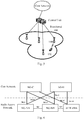
- 5G network architecture is illustrated in Fig. 4 , where the network architecture includes three logical entities: NG-C (control plane function entity of core network) and NG-U (user plane function entity of core network) located in core network, and gNB (next generation base station) and eLTE eNB (base station of evolved LTE) located in access network.
- NG-C control plane function entity of core network
- NG-U user plane function entity of core network
- gNB next generation base station
- eLTE eNB base station of evolved LTE
- a NG-C interface is established between the NG-C and the gNB to transmit control plane signaling
- a NG-U is established between the NG-U and the gNB to transmit user plane data.
- An Xn interface supporting both control plane function (e.g., Xn-C) and user plane function (e.g., Xn-U), is established between gNBs of radio access network.
- a control plane connection at the granularity of UE may be established on the NG-C (where the control plane connection corresponding to each UE may be identified with a NG-AP ID), and a user plane connection (or referred to as user plane tunnel) at the granularity of PDU session may be established on the NG-U.
- a UE can only maintain one NG-C connection to the NG-C at a time; however, the UE may establish multiple user plane connections (or user plane tunnels) at the granularity of PDU session to NG-U on the NG-U interfaces.
- the dual connectivity mechanism is to reduce the load of the Master RAN.
- a UE accesses the Master RAN, control plane message is exchanged between the Master RAN and the UE, and the Master RAN may opt to migrate a part of or all of bearers to a Secondary RAN to transmit to the UE, as shown in Fig. 5 .
- MCG bearer Master Cell Group bearer
- SCG bearer Secondary Cell Group bearer
- Split bearer SCG split bearer
- the future 5G core network forgoes the concept of bearer, and QoS parameter issued by the NG-C of the core network to the gNB are configured at the granularity of flow.
- the gNB of the access network still performs QoS management at the granularity of RB, it is needed for the access network to generate QoS parameter at RB level for interaction process between gNB and UE and interaction process between gNB and other radio access entity.
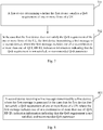
- a method of QoS processing according to an embodiment is illustrated, the method including the following steps.
- Step 701 a first device determining whether the first device satisfies a QoS requirement of one or more flows of a UE.
- the determination may be performed through two modes as follows: (1) the first device determining whether the first device satisfies the QoS requirement of the one or more flows of the UE in accordance with QoS parameter(s) of the one or more flows; (2) the first device determining whether the first device satisfies the QoS requirement of the one or more flows of the UE in accordance with the QoS parameter(s) of the one or more flows and a mapping relation between data radio bearer (DRB) and flow.
- DRB data radio bearer
- Step 702 in the case that the first device can't satisfy the QoS requirement of the one or more flows of the UE, the first device transmitting a first message to a second device; where the first message includes one of or a combination of more than one of: QoS flow identifier (QFI), radio bearer (RB) ID, indication information indicating that the QoS requirement can't be satisfied, or recommended QoS parameter.
- QFI QoS flow identifier
- RB radio bearer
- the method of QoS processing according to the embodiment may be applicable to a multi connectivity scenario, e.g., a multi connectivity SCG bearer or multi connectivity SCG split bearer scenario; or, the method of QoS processing according to the embodiment may be applicable to a CU-DU scenario.
- a multi connectivity SCG bearer or multi connectivity SCG split bearer scenario the first device is a secondary base station, and the second device is primary base station; and in the CU-DU scenario, the first device is the DU and the second device is the CU.
- the method prior to establishing the multi connectivity for the UE, the method further includes: the first device receiving the QoS parameter(s) of the one or more flows transmitted by the second device and the mapping relation between DRB and flow on the second device.
- the QoS parameter includes a suggested guaranteed bit rate and/or a suggested maximum bit rate.
- the first device in the multi connectivity scenario or the CU-DU scenario, can transmit the first message to the second device when the first device can't satisfy the QoS requirement, where the first message includes one of or a combination of more than one of: QFI, RB ID, indication information indicating that the QoS requirement can't be satisfied, or recommended QoS parameter.
- the first device may act accordingly to satisfy the QoS requirement.
- a process of a method of QoS processing is illustrated, the method including the following specific steps.
- Step 801 a second device receiving a first message transmitted by a first device, where the first message is generated in the case that the first device can't satisfy a QoS requirement of one or more flows of a UE; where the first message includes one of or a combination of more than one of: QoS Flow Identifier (QFI), Radio Bearer (RB) ID, indication information indicating that the QoS requirement can't be satisfied, or recommended QoS parameter.
- QFI QoS Flow Identifier
- RB Radio Bearer
- the method of QoS processing according to the embodiment may be applicable to a multi connectivity scenario, e.g., a multi connectivity SCG bearer or multi connectivity SCG split bearer scenario; or, the method of QoS processing according to the embodiment may be applicable to a CU-DU scenario.
- a multi connectivity SCG bearer or multi connectivity SCG split bearer scenario the first device is a secondary base station, and the second device is a primary base station; and in the CU-DU scenario, the first device is a DU and the second device is a CU.
- the method further includes: the second device determining whether a bearer type change is needed in accordance with the first message.
- the method further includes: the second device transmitting a second message to a core network in accordance with the first message.
- the second message includes one of or a combination of more than one of: the QFI, the indication information indicating that the QoS requirement can't not be satisfied, or a suggested QoS parameter.
- the QoS parameter includes a suggested guaranteed bit rate and/or a suggested maximum bit rate.
- the first device in the multi connectivity scenario or the CU-DU scenario, can transmit the first message to the device when the first device can't satisfy the QoS requirement, where the first message includes one of or a combination of more than one of: QFI, RB ID, indication information indicating that the QoS requirement is not satisfied, or recommended QoS parameter.
- the first device may act accordingly to satisfy the QoS requirement.
- the QoS parameter includes a guaranteed bit rate (GBR) and/or a maximum bit rate (MBR).
- GBR guaranteed bit rate
- MRR maximum bit rate
- the first embodiment in the multi connectivity SCG bearer/SCG split bearer scenario, the Secondary Node reports QFI of flow and/or recommended QoS parameter, as shown in Fig. 9 .
- step 6 is optional.
- the MeNB may determine whether the flow QoS requirement may be satisfied in accordance with the resource usage of the MeNB; if the flow QoS requirement can't be satisfied, the MeNB initiates a PDU Session modification request carrying the flow QFI and/or suggested QoS information.
- the second embodiment in the multi connectivity split bearer scenario, the Secondary Node reports the RB ID and/or recommended QoS parameter.
- the second embodiment is similar to the first embodiment except for the step 5 and step 6, wherein if the Secondary Node determines that the requirement of the QoS flow can't be satisfied in accordance with QoS parameter of flow and DRB-flow mapping relation, the Secondary Node transmits a Secondary Node modification request message, carrying the RB ID and/or suggested QoS parameter, to the Master RAN.
- the third embodiment in the CU-DU scenario, the Secondary Node reports RB ID and/or recommended QoS parameter (also referred to as suggested QoS parameter), as shown in Fig. 10 , which including the following steps.
- embodiments of the present disclosure also provide a first device. Since the problem-solving principle of the first device is similar to the method of QoS processing as shown in Fig. 7 according to the embodiments of the present disclosure, the implementation of the first device may be learned by referring to the implementation of the method, thus a repeated description is omitted.
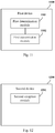
- the first device 1100 includes: a first determination module 1101, configured to determine whether the first device satisfies a QoS requirement of one or more flows of a UE; and a first transmission module 1102, configured to, in the case that the first device can't satisfy the QoS requirement of the one or more flows of the UE, transmit a first message to a second device; where the first message includes one of or a combination of more than one of: QoS flow identifier (QFI), radio bearer (RB) ID, indication information indicating that the QoS requirement is not satisfied, or recommended QoS parameter.
- QFI QoS flow identifier
- RB radio bearer
- the first device is a secondary base station and the second device is a primary base station; or the first device is a DU and the second device is a CU.
- the first determination module 1101 is configured to: determine whether the first device satisfies the QoS requirement of the one or more flows of the UE in accordance with QoS parameter(s) of the one or more flows or in accordance with the QoS parameter(s) of the one or more flows and a mapping relation between data radio bearer (DRB) and flow.
- DRB data radio bearer
- the first device 1100 further includes: a first reception module, configured to receive the QoS parameter(s) of the one or more flows transmitted by the second device and the mapping relation between DRB and flow on the second device.
- a first reception module configured to receive the QoS parameter(s) of the one or more flows transmitted by the second device and the mapping relation between DRB and flow on the second device.
- the QoS parameter includes a suggested guaranteed bit rate and/or a suggested maximum bit rate.
- the first device in a multi connectivity scenario or a CU-DU scenario, can transmit the first message to the device when the first device can't satisfy the QoS requirement, where the first message includes one of or a combination of more than one of: QFI, RB ID, indication information indicating that the QoS requirement is not satisfied, or recommended QoS parameter.
- the first device may act accordingly to satisfy the QoS requirement.
- embodiments of the present disclosure further provide a second device. Since the problem-solving principle of the second device is similar to the method of QoS processing as shown in Fig. 8 according to the embodiments of the present disclosure, the implementation of the second device may be learned by referring to the implementation of the method, thus a repeated description is omitted.
- the second device 1200 includes: a second reception module 1201, configured to receive a first message transmitted by a first device, where the first message is generated in the case that the first device can't satisfy QoS requirement of one or more flows of a UE; where the first message includes one of or a combination of more than one of: QoS flow identifier (QFI), radio bearer (RB) ID, indication information indicating that the QoS requirement is not satisfied, or recommended QoS parameter.
- QFI QoS flow identifier
- RB radio bearer
- the first device is a secondary base station and the second device is a primary base station; or the first device is a DU and the second device is a CU.
- the second device 1200 further includes: a second determination module, configured to determine whether a bearer type change is needed in accordance with the first message; or a second transmission module, configured to transmit a second message to a core network in accordance with the first message.
- the second message includes one of or a combination of more than one of: the QFI, the indication information indicating that the QoS requirement is not satisfied, or a suggested QoS parameter.
- the QoS parameter includes a suggested guaranteed bit rate and/or a suggested maximum bit rate.
- the first device in a multi connectivity scenario or a CU-DU scenario, can transmit the first message to the second device when the first device can't satisfy the QoS requirement, where the first message includes one of or a combination of more than one of: QFI, RB ID, indication information indicating that the QoS requirement is not satisfied, or recommended QoS parameter.
- the first device may act accordingly to satisfy the QoS requirement.
- a network device is further provided in an embodiment, which including a memory, a processor and a computer program stored on the memory and executable by the processor, where the processor is configured to execute the computer program to implement steps of the methods of QoS processing described above.
- a first device including: a first processor 1304, configured to read program in a first memory 1305 and implement the following process: determining whether the first device satisfies a QoS requirement of one or more flows of a UE; and in the case that the first device can't satisfy the QoS requirement of the one or more flows of the UE, transmitting a first message to a second device; where the first message includes one of or a combination of more than one of: QoS flow identifier (QFI), radio bearer (RB) ID, indication information indicating that the QoS requirement is not satisfied, or recommended QoS parameter; and a first transceiver 1301, configured to receive and transmit data under the control of the first processor 1304.
- QFI QoS flow identifier
- RB radio bearer
- a bus architecture (represented by a first bus 1300) may include an arbitrary quantity of buses and bridges connected to each other.
- Various circuits including one or more processors represented by the first processor 1304 and a memory represented by the first memory 1305 are coupled via the first bus 1300.
- the first bus 1300 may further couple other circuits together, such as a periphery component, a voltage stabilizer and a power management circuit, which is well known in the art and is not repeated herein.
- a first bus interface 1303 provides an interface between the first bus 1300 and the first transceiver 1301.
- the first transceiver 1301 may be one element, or may be multiple elements, such as multiple receivers and transmitters.
- the first transceiver 1301 provides a unit configured to communicate with other devices on a transmission medium. Data processed by the first processor 1304 is transmitted via the first transceiver 1301 and the first antenna 1302 on a radio medium. Furthermore, the first antenna 1302 receives data and transmits the data to the first processor 1304 via the first transceiver 1301.
- the first processor 1304 is in charge of managing the first bus 1300 and common processes, and may further provide various functions, e.g., timing, periphery interfaces, voltage adjusting, power source management and other controlling functions.
- the first memory 1305 may be configured to store data to be used by the first processor 1304 when performing operations.
- the first processor 1304 may be CPU, application specific integrated circuit (ASIC), field-programmable gate array (FPGA) or complex programmable logic device (CPLD).
- a second device including: a second processor 1404, configured to read program in a second memory 1405 and implement the following process: receiving a first message transmitted by a first device, where the first message is generated in the case that the first device can't satisfy a QoS requirement of one or more flows of a UE; where the first message includes one of or a combination of more than one of: QoS flow identifier (QFI), radio bearer (RB) ID, indication information indicating that the QoS requirement is not satisfied, or recommended QoS parameter; and a second transceiver 1401, configured to receive and transmit data under the control of the second processor 1404.
- QFI QoS flow identifier
- RB radio bearer
- a bus architecture (represented by a second bus 1400) may include an arbitrary quantity of buses and bridges connected to each other.
- Various circuits including one or more processors represented by the second processor 1404 and a memory represented by the second memory 1405 are coupled via the first bus 1400.
- the second bus 1400 may further couple various other circuits together, such as a periphery component, a voltage stabilizer and a power management circuit, which is well known in the art and is not repeated herein.
- a second bus interface 1403 provides an interface between the second bus 1400 and the second transceiver 1401.
- the second transceiver 1401 may be one element, or may be multiple elements, such as multiple receivers and transmitters.
- the second transceiver 1401 provides a unit configured to communicate with other devices on a transmission medium. Data processed by the second processor 1404 is transmitted via the second transceiver 1401 and the second antenna 1402 on a radio medium. Furthermore, the second antenna 1402 receives data and transmits the data to the second processor 1404 via the second transceiver 1401.
- the second processor 1404 is in charge of managing the second bus 1400 and common processes, and may further provide various functions, e.g., timing, periphery interfaces, voltage adjusting, power source management and other controlling functions.
- the second memory 1405 may be configured to store data to be used by the second processor 1404 performing operations.
- the second processor 1404 may be CPU, application specific integrated circuit (ASIC), field-programmable gate array (FPGA) or complex programmable logic device (CPLD).
- a computer readable storage medium storing therein a computer program (instructions) is also provided in an embodiment, and steps of the methods of QoS processing described above are performed when the computer program (instructions) is executed by a processor.
- B corresponding to A indicates that B is associated with A and may be determined based on A.
- determining B based on A does not mean determining B based on only A, and B may be determined based on A and/or other information.
- the method and device provided in the embodiments of the present disclosure may be implemented in other ways.
- the described embodiments directed to the device are merely exemplary.
- the units are divided merely in logical function, which may be divided in another way in actual implementation, e.g., multiple units or components may be combined or integrated into another system, or some features may be ignored or not performed.
- the disclosed or discussed mutual coupling or direct coupling or communication connection may be an indirect coupling or communication connection through some interfaces, devices or units, which may be implemented in electronic, mechanical or other forms.
- functional units in the embodiments of the present disclosure may be integrated into one processing unit, or may be physically independent, or two or more units are integrated into one unit.
- the integrated units may be implemented by hardware or by combination of hardware and software.
- Integrated units implemented as software functional units may be stored on a computer readable storage medium.
- the software functional units are stored on a storage medium and include several instructions for enabling a computer device (which may be a personal computer, a server, a network apparatus or the like) to execute partial steps of methods according to embodiments of the present disclosure.
- the storage medium may include medium that can store program code, such as a USB flash disk, a mobile Hard Disk, a Read-Only Memory (ROM), a Random Access Memory (RAM), a magnetic disk or an an optical disk.
Landscapes
- Engineering & Computer Science (AREA)
- Computer Networks & Wireless Communication (AREA)
- Signal Processing (AREA)
- Quality & Reliability (AREA)
- Mobile Radio Communication Systems (AREA)
Abstract
Description
- The present application claims a priority to Chinese patent application No.
201710186478.1 - The present disclosure relates to the field of communication technology, in particular to a method and a device of quality of service (QoS) processing.
- In conventional Long Term Evolution (LTE) system, if current air interface resources can't satisfy QoS requirements, the Evolved Radio Access Bearer (E-RAB) will be released proactively and Core Network will be notified. In New Radio (NR) system, for Guaranteed Bit Rate (GBR) service, the notification control in the QoS parameters indicates whether the Core Network may be notified if the QoS of a certain flow can't be satisfy by the Radio Access Network (RAN) side. It means that in 5G system, for the GBR service, the radio access side is permitted to inform the Core Network that the current radio network condition can't satisfy the QoS requirements of the GBR service.
- In a multi connectivity scenario, QoS flow may be split to a Secondary Node (secondary base station), thus what to do in the case that the QoS can't be satisfied by the Secondary Node needs to be taken into consideration. In a Central Unit (CU) - Distributed Unit (DU) split scenario, what to do in the case that the QoS can't be satisfied by the DU needs to be taken into consideration.
- In conventional LTE system, if current air interface resources can't satisfy the QoS requirements, the E-RAB will be released proactively and the Core Network will be notified, thereby impacting service performance. At present, there is no mechanism for managing the GRB flow for multi connectivity scenario and CU-DU scenario at the RAN side.
- In view of the above, embodiments of the present disclosure provide a method and a device of QoS processing, such that in the case that a first device can't satisfy a QoS requirement in a multi connectivity scenario or a CU-DU scenario in a 5G system, the first device may act accordingly to satisfy the QoS requirement.
- In a first aspect of embodiments of the present disclosure, a method of QoS processing is provided, the method including: a first device determining whether the first device satisfies a QoS requirement of one or more flows of a UE; and in the case that the first device does not satisfy the QoS requirement of the one or more flows of the UE, the first device transmitting a first message to a second device; where the first message includes one of or a combination of more than one of: QoS flow identifier (QFI), radio bearer (RB) ID, indication information indicating that the QoS requirement is not satisfied, or recommended QoS parameters.
- Optionally, the first device determining whether the first device satisfies the QoS requirement of the one or more flows of the UE includes: the first device determining whether the first device satisfies the QoS requirement of the one or more flows of the UE in accordance with QoS parameter(s) of the one or more flows or in accordance with the QoS parameter(s) of the one or more flows and a mapping relation between data radio bearer (DRB) and flow.
- Optionally, the method further includes: the first device receiving the QoS parameter(s) of the one or more flows transmitted by the second device and the mapping relation between DRB and flow on the second device.
- Optionally, the first device is a secondary base station and the second device is a primary base station; or the first device is a distributed unit (DU) and the second device is a central unit (CU).
- Optionally, the QoS parameter includes a suggested guaranteed bit rate and/or a suggested maximum bit rate.
- In a second aspect of embodiments of the present disclosure, a method of QoS processing is further provided, the method including: a second device receiving a first message transmitted by a first device, where the first message is generated in the case that the first device does not satisfy QoS requirement of one or more flows of a UE; where the first message includes one of or a combination of more than one of: QoS flow identifier (QFI), radio bearer (RB) ID, indication information indicating that the QoS requirement is not satisfied, or recommended QoS parameter.
- Optionally, the method further includes: the second device determining whether a bearer type change is needed in accordance with the first message; or the second device transmitting a second message to a core network in accordance with the first message.
- Optionally, the second message includes one of or a combination of more than one of: the QFI, the indication information indicating that the QoS requirement is not satisfied, or a suggested QoS parameter.
- Optionally, the first device is a secondary base station and the second device is a primary base station; or the first device is a DU and the second device is a CU.
- Optionally, the QoS parameter includes a suggested guaranteed bit rate and/or a suggested maximum bit rate.
- In a third aspect of embodiments of the present disclosure, a first device is further provided, the first device including: a first determination module, configured to determine whether the first device satisfies a QoS requirement of one or more flows of a UE; and a first transmission module, configured to transmit, in the case that the first device does not satisfy the QoS requirement of the one or more flows of the UE, a first message to a second device; where the first message includes one of or a combination of more than one of: QoS flow identifier (QFI), radio bearer (RB) ID, indication information indicating that the QoS requirement is not satisfied, or recommended QoS parameter.
- Optionally, the first determination module is configured to: determine whether the first device satisfies the QoS requirement of the one or more flows of the UE, in accordance with QoS parameter(s) of the one or more flows or in accordance with the QoS parameter(s) of the one or more flows and a mapping relation between data radio bearer (DRB) and flow.
- Optionally, the first device further includes: a first reception module, configured to receive the QoS parameter(s) of the one or more flows transmitted by the second device and the mapping relation between DRB and flow on the second device.
- Optionally, the first device is a secondary base station e and the second device is a primary base station; or the first device is a DU and the second device is a CU.
- Optionally, the QoS parameter includes a suggested guaranteed bit rate and/or a suggested maximum bit rate.
- In a fourth aspect of embodiments of the present disclosure, a second device is further provided, the second device including: a second reception module, configured to receive a first message transmitted by a first device, where the first message is generated in the case that the first device does not satisfy a QoS requirement of one or more flows of a UE; where the first message includes one of or a combination of more than one of: QoS flow identifier (QFI), radio bearer (RB) ID, indication information indicating that the QoS requirement is not satisfied, or recommended QoS parameter.
- Optionally, the second device further includes: a second determination module, configured to determine whether a bearer type change is needed in accordance with the first message; or a second transmission module, configured to transmit a second message to a core network in accordance with the first message.
- Optionally, the second message includes one of or a combination of more than one of: the QFI, the indication information indicating that the QoS requirement is not satisfied, or a suggested QoS parameter.
- Optionally, the first device is a secondary base station and the second device is a primary base station; or the first device is a DU and the second device is a CU.
- Optionally, the QoS parameter includes a suggested guaranteed bit rate and/or a suggested maximum bit rate.
- In a fifth aspect of embodiments of the present disclosure, a network device is further provided, including a memory, a processor and a computer program stored on the memory and executable by the processor, where the processor is configured to execute the computer program to implement steps of the method of QoS processing described above.
- In a sixth aspect of embodiments of the present disclosure, a computer readable storage medium having a computer program stored thereon is further provided, where steps of the method of QoS processing described above are implemented when the computer program is executed by a processor.
- A technical solution of the aforementioned technical solutions has advantages or beneficial effects as follows. Based on the embodiments of the present disclosure, in a multi connectivity scenario or a CU-DU scenario, the first device can transmit the first message to the second device in the case that the first device does not satisfy the QoS requirement, where the first message includes one of or a combination of more than one of: QFI, RB ID, indication information indicating that the QoS requirement is not satisfied, or recommended QoS parameter. In this way, when the first device does not satisfy the QoS requirement in the multi connectivity scenario or the CU-DU scenario in the 5G system, the first device can act accordingly to satisfy the QoS requirement, so as to solve the problem in the related technologies that E-RAB will be released proactively if current air interface resources can't satisfy a QoS requirement.
-
-
Fig. 1 is a schematic structural diagram of a bearer model in LTE system according to related technologies; -
Fig. 2 is a schematic diagram of a NR architecture according to related technologies; -
Fig. 3 is a schematic diagram of an architecture of a 5G communication system; -
Fig. 4 is a schematic diagram of a 5G network architecture; -
Fig. 5 is a schematic diagram of dual connectivity; -
Fig. 6 is another schematic diagram of dual connectivity; -
Fig. 7 is a flow diagram of a method of QoS processing according to an embodiment; -
Fig. 8 is a flow diagram of a method of QoS processing according to another embodiment; -
Fig. 9 is a flow diagram of a process in which a Secondary Node reports QFI of flow and/or recommended QoS parameter in multi connectivity SCG bearer or SCG split bearer scenario according to an embodiment; -
Fig. 10 is a flow diagram of a process in which a Secondary Node reports RB ID and/or recommended QoS parameter in CU-DU scenario according to an embodiment; -
Fig. 11 is a structural diagram of a first device according to an embodiment; -
Fig. 12 is a structural diagram of a second device according to an embodiment; -
Fig. 13 is a structural diagram of a first device according to another embodiment; and -
Fig. 14 is a structural diagram of a second device according to another embodiment. - Exemplary embodiments of the present disclosure are detailed in conjunction with drawings. It should be noted, the present disclosure may be implemented in various ways although the exemplary embodiments are illustrated in the drawings. The embodiments provided herein are not to limit the present disclosure, and on the contrary, they are provided for thoroughly understanding the present disclosure and completely conveying the scope of the present disclosure to those skilled in the art.
- Referring to
Fig. 1 , in conventional LTE system, core network is responsible for generation of QoS parameter of E-RAB, and since there is a one-to-one mapping relation between air interface Radio Bearer (RB) and the E-RAB, the E-RAB QoS parameter generated by the core network are directly used as QoS parameter of the air interface RB. - Embodiments of the present disclosure may be applied in various network deployment structures. For convenience, two types of network deployment structures which may be employed in the future mobile communication are introduced.
- The first deployment structure: base station + user equipment
- Referring to
Fig. 2 , a typical New Radio (NR) architecture is illustrated. A gNB (base station) has multiple cells and the UE transmits/receives air interface data to/from the cell in a connected state. - The second deployment structure: network side node includes Central Unit (CU) and Distributed Unit (DU), and user side node includes UE.
- Referring to
Fig. 3 , an architecture which may be employed in the future 5G mobile communication is illustrated. The network side node includes CU and DU, where one CU controls multiple DUs deployed in a certain area, and these DUs perform air interface transmission with the UE via Transmission Reception Point (TRP). One or more TRPs may serve a UE to perform data transmission at the same time. - Embodiments of the present disclosure are applicable to the two RAN architectures described above.
- 5G network architecture is illustrated in
Fig. 4 , where the network architecture includes three logical entities: NG-C (control plane function entity of core network) and NG-U (user plane function entity of core network) located in core network, and gNB (next generation base station) and eLTE eNB (base station of evolved LTE) located in access network. A NG-C interface is established between the NG-C and the gNB to transmit control plane signaling; and a NG-U is established between the NG-U and the gNB to transmit user plane data. An Xn interface, supporting both control plane function (e.g., Xn-C) and user plane function (e.g., Xn-U), is established between gNBs of radio access network. - A control plane connection at the granularity of UE may be established on the NG-C (where the control plane connection corresponding to each UE may be identified with a NG-AP ID), and a user plane connection (or referred to as user plane tunnel) at the granularity of PDU session may be established on the NG-U. A UE can only maintain one NG-C connection to the NG-C at a time; however, the UE may establish multiple user plane connections (or user plane tunnels) at the granularity of PDU session to NG-U on the NG-U interfaces. In radio access network, there may be one or more gNBs serving the UE at the same time.
- Currently, dual connectivity mechanism is supported in LTE system. The dual connectivity mechanism is to reduce the load of the Master RAN. In the mechanism, a UE accesses the Master RAN, control plane message is exchanged between the Master RAN and the UE, and the Master RAN may opt to migrate a part of or all of bearers to a Secondary RAN to transmit to the UE, as shown in
Fig. 5 . - As illustrated in
Fig. 6 , in the dual connectivity scenario, there are bear types including MCG bearer (Master Cell Group bearer), SCG bearer (Secondary Cell Group bearer), Split bearer and SCG split bearer. - The future 5G core network forgoes the concept of bearer, and QoS parameter issued by the NG-C of the core network to the gNB are configured at the granularity of flow. On the other hand, since the gNB of the access network still performs QoS management at the granularity of RB, it is needed for the access network to generate QoS parameter at RB level for interaction process between gNB and UE and interaction process between gNB and other radio access entity.
- Referring to
Fig. 7 , a method of QoS processing according to an embodiment is illustrated, the method including the following steps. -
Step 701, a first device determining whether the first device satisfies a QoS requirement of one or more flows of a UE. - In the embodiment, the determination may be performed through two modes as follows: (1) the first device determining whether the first device satisfies the QoS requirement of the one or more flows of the UE in accordance with QoS parameter(s) of the one or more flows; (2) the first device determining whether the first device satisfies the QoS requirement of the one or more flows of the UE in accordance with the QoS parameter(s) of the one or more flows and a mapping relation between data radio bearer (DRB) and flow.
-
Step 702, in the case that the first device can't satisfy the QoS requirement of the one or more flows of the UE, the first device transmitting a first message to a second device; where the first message includes one of or a combination of more than one of: QoS flow identifier (QFI), radio bearer (RB) ID, indication information indicating that the QoS requirement can't be satisfied, or recommended QoS parameter. - The method of QoS processing according to the embodiment may be applicable to a multi connectivity scenario, e.g., a multi connectivity SCG bearer or multi connectivity SCG split bearer scenario; or, the method of QoS processing according to the embodiment may be applicable to a CU-DU scenario. In the multi connectivity SCG bearer or multi connectivity SCG split bearer scenario, the first device is a secondary base station, and the second device is primary base station; and in the CU-DU scenario, the first device is the DU and the second device is the CU.
- In the multi connectivity scenario, prior to establishing the multi connectivity for the UE, the method further includes: the first device receiving the QoS parameter(s) of the one or more flows transmitted by the second device and the mapping relation between DRB and flow on the second device.
- In the embodiment, optionally, the QoS parameter includes a suggested guaranteed bit rate and/or a suggested maximum bit rate.
- Based on the embodiments of the present disclosure, in the multi connectivity scenario or the CU-DU scenario, the first device can transmit the first message to the second device when the first device can't satisfy the QoS requirement, where the first message includes one of or a combination of more than one of: QFI, RB ID, indication information indicating that the QoS requirement can't be satisfied, or recommended QoS parameter. In this way, when the first device can't satisfy the QoS requirement in the multi connectivity scenario or the CU-DU scenario in the 5G system, the first device may act accordingly to satisfy the QoS requirement.
- Referring to
Fig. 8 , a process of a method of QoS processing is illustrated, the method including the following specific steps. -
Step 801, a second device receiving a first message transmitted by a first device, where the first message is generated in the case that the first device can't satisfy a QoS requirement of one or more flows of a UE; where the first message includes one of or a combination of more than one of: QoS Flow Identifier (QFI), Radio Bearer (RB) ID, indication information indicating that the QoS requirement can't be satisfied, or recommended QoS parameter. - The method of QoS processing according to the embodiment may be applicable to a multi connectivity scenario, e.g., a multi connectivity SCG bearer or multi connectivity SCG split bearer scenario; or, the method of QoS processing according to the embodiment may be applicable to a CU-DU scenario. In the multi connectivity SCG bearer or multi connectivity SCG split bearer scenario, the first device is a secondary base station, and the second device is a primary base station; and in the CU-DU scenario, the first device is a DU and the second device is a CU.
- Optionally, in the multi connectivity scenario, the method further includes: the second device determining whether a bearer type change is needed in accordance with the first message.
- Optionally, in the CU-DU scenario, the method further includes: the second device transmitting a second message to a core network in accordance with the first message.
- Further, the second message includes one of or a combination of more than one of: the QFI, the indication information indicating that the QoS requirement can't not be satisfied, or a suggested QoS parameter.
- In the embodiment, optionally, the QoS parameter includes a suggested guaranteed bit rate and/or a suggested maximum bit rate.
- Based on the embodiments of the present disclosure, in the multi connectivity scenario or the CU-DU scenario, the first device can transmit the first message to the device when the first device can't satisfy the QoS requirement, where the first message includes one of or a combination of more than one of: QFI, RB ID, indication information indicating that the QoS requirement is not satisfied, or recommended QoS parameter. In this way, when the first device can't satisfy the QoS requirement in the multi connectivity scenario or the CU-DU scenario in the 5G system, the first device may act accordingly to satisfy the QoS requirement.
- Hereinafter, the process of the method of QoS processing is explained with reference to the dual connectivity scenario and the CU-DU scenario.
- (1) if core network sets notification control for one or more QoS flows: in the dual connectivity scenario, during the process of adding the Secondary Node (secondary base station), the Master Node (primary base station) may transmit QoS parameter of flow on which split is performed, DRB-flow mapping relation and QoS parameter of RB to the Secondary Node. After the process is completed, if resources of the Secondary Node can't satisfy the QoS requirement, one or more of related QFI, RB ID or recommended QoS parameter need to be reported to the Master Node. The Master Node determines, based on its policy, whether to perform a bearer type change or to notify the core network and report the related QFI and/or recommended QoS parameter to the core network.
- (2) if core network sets notification control for one or more QoS flows: in the CU-DU scenario, during the process of the CU selecting the DU for the UE, the establishment request message may include QoS parameter of flow and DRB-flow mapping relation, in addition to QoS parameter of RB. After the process is completed, if resources of the DU can't satisfy the QoS requirement, related RB ID and recommended QoS parameter need to be reported to the CU, and the CU reports related QFI and/or recommended QoS parameter to the core network.
- Optionally, the QoS parameter includes a guaranteed bit rate (GBR) and/or a maximum bit rate (MBR).
- The first embodiment: in the multi connectivity SCG bearer/SCG split bearer scenario, the Secondary Node reports QFI of flow and/or recommended QoS parameter, as shown in
Fig. 9 . -
Step 1, the UE establishes a user plane connection to the NGU via the Master RAN. -
Step 2, the Master RAN selects the Secondary RAN, and determines to split a part of data flow of the PDU session to the Secondary RAN. - Step 3, the Master RAN adds the Secondary RAN through the Xn interface, where the request message carries QoS parameter of flow (including per flow notification control).
-
Step 4, the Master RAN updates path information, and creates a tunnel from the Secondary RAN to the NGU. -
Step 5, after the dual connectivity is established for the UE, if the Secondary Node determines that requirement of QoS flow can't be satisfied, the Secondary Node transmits a Secondary Node modification request message carrying the QFI and/or suggested QoS parameter to the Master RAN. -
Step 6, the Master Node replies with a response message. - It is noted that,
step 6 is optional. - The subsequent operations of the Master Node are as follows.
- Scheme 1: the Master Node determines whether to perform a bearer type change, e.g., change into a MCG bearer, in accordance with the QoS information transmitted by the Secondary Node, and the MeNB (macro eNB) may initiate an Xn Secondary Node modification or release process to complete the bearer type change. For a SCG split bearer, the Master Node may re-negotiate RB QoS with the Secondary Node, and the Master Node may initiate a Secondary Node modification process to complete the negotiation of the RB parameters.
- Scheme 2: the Master Node may directly initiate a PDU Session modification request, carrying the QFI and/or QoS information reported by the Secondary Node, to the core network in accordance with the QoS information transmitted by the Secondary Node.
- It is noted, the
Scheme 1 andScheme 2 may be used in conjunction. For example, after theScheme 1 is performed, the MeNB may determine whether the flow QoS requirement may be satisfied in accordance with the resource usage of the MeNB; if the flow QoS requirement can't be satisfied, the MeNB initiates a PDU Session modification request carrying the flow QFI and/or suggested QoS information. - The second embodiment: in the multi connectivity split bearer scenario, the Secondary Node reports the RB ID and/or recommended QoS parameter.
- The second embodiment is similar to the first embodiment except for the
step 5 andstep 6, wherein if the Secondary Node determines that the requirement of the QoS flow can't be satisfied in accordance with QoS parameter of flow and DRB-flow mapping relation, the Secondary Node transmits a Secondary Node modification request message, carrying the RB ID and/or suggested QoS parameter, to the Master RAN. - The subsequent operations of the Master Node are as follows.
- Scheme 1: the Master Node determines whether to perform a bearer type change, e.g., change into a MCG bearer, in accordance with the QoS information transmitted by the Secondary Node, and the MeNB may initiate an Xn Secondary Node modification or release process to complete the bearer type change; or the Master Node may re-negotiate RB QoS with the Secondary Node, and the Master Node may initiate a Secondary Node modification process to complete the negotiation of the RB parameters.
- Scheme 2: having received the QoS information transmitted by the Secondary Node, the Master Node, in accordance with its own resource status, directly initiates a PDU Session modification request, carrying the QFI of the QoS flow and/or suggested QoS parameter. to the core network.
- The third embodiment: in the CU-DU scenario, the Secondary Node reports RB ID and/or recommended QoS parameter (also referred to as suggested QoS parameter), as shown in
Fig. 10 , which including the following steps. - Step 1: the Secondary Node determines that the QoS flow requirement can't be satisfied in accordance with QoS parameter of flow and DRB-flow mapping relation.
- Step 2: the Secondary Node transmits a UE context modification request message to the Master RAN, where the message carries RB ID and/or suggested QoS parameter.
- Step 3: optionally, the CU returns an acknowledge response.
- Step 4: the CU initiates a modification request, carrying the QFI of the QoS flow and/or suggested QoS parameter, to the core network.
- Based on the same inventive concept, embodiments of the present disclosure also provide a first device. Since the problem-solving principle of the first device is similar to the method of QoS processing as shown in
Fig. 7 according to the embodiments of the present disclosure, the implementation of the first device may be learned by referring to the implementation of the method, thus a repeated description is omitted. - Referring to
Fig. 11 , the structure of the first device according to an embodiment is illustrated. Thefirst device 1100 includes: afirst determination module 1101, configured to determine whether the first device satisfies a QoS requirement of one or more flows of a UE; and afirst transmission module 1102, configured to, in the case that the first device can't satisfy the QoS requirement of the one or more flows of the UE, transmit a first message to a second device; where the first message includes one of or a combination of more than one of: QoS flow identifier (QFI), radio bearer (RB) ID, indication information indicating that the QoS requirement is not satisfied, or recommended QoS parameter. - In the embodiment, optionally, the first device is a secondary base station and the second device is a primary base station; or the first device is a DU and the second device is a CU.
- In the embodiment, optionally, the
first determination module 1101 is configured to: determine whether the first device satisfies the QoS requirement of the one or more flows of the UE in accordance with QoS parameter(s) of the one or more flows or in accordance with the QoS parameter(s) of the one or more flows and a mapping relation between data radio bearer (DRB) and flow. - In the embodiment, optionally, the
first device 1100 further includes: a first reception module, configured to receive the QoS parameter(s) of the one or more flows transmitted by the second device and the mapping relation between DRB and flow on the second device. - In the embodiment, optionally, the QoS parameter includes a suggested guaranteed bit rate and/or a suggested maximum bit rate.
- Based on the embodiments of the present disclosure, in a multi connectivity scenario or a CU-DU scenario, the first device can transmit the first message to the device when the first device can't satisfy the QoS requirement, where the first message includes one of or a combination of more than one of: QFI, RB ID, indication information indicating that the QoS requirement is not satisfied, or recommended QoS parameter. In this way, when the first device can't satisfy the QoS requirement in the multi connectivity scenario or the CU-DU scenario in the 5G system, the first device may act accordingly to satisfy the QoS requirement.
- Based on the same inventive concept, embodiments of the present disclosure further provide a second device. Since the problem-solving principle of the second device is similar to the method of QoS processing as shown in
Fig. 8 according to the embodiments of the present disclosure, the implementation of the second device may be learned by referring to the implementation of the method, thus a repeated description is omitted. - Referring to
Fig. 12 , the structure of the second device according to an embodiment is illustrated. Thesecond device 1200 includes: asecond reception module 1201, configured to receive a first message transmitted by a first device, where the first message is generated in the case that the first device can't satisfy QoS requirement of one or more flows of a UE; where the first message includes one of or a combination of more than one of: QoS flow identifier (QFI), radio bearer (RB) ID, indication information indicating that the QoS requirement is not satisfied, or recommended QoS parameter. - In the embodiment, optionally, the first device is a secondary base station and the second device is a primary base station; or the first device is a DU and the second device is a CU.
- In the embodiment, optionally, the
second device 1200 further includes: a second determination module, configured to determine whether a bearer type change is needed in accordance with the first message; or a second transmission module, configured to transmit a second message to a core network in accordance with the first message. - In the embodiment, optionally, the second message includes one of or a combination of more than one of: the QFI, the indication information indicating that the QoS requirement is not satisfied, or a suggested QoS parameter.
- In the embodiment, optionally, the QoS parameter includes a suggested guaranteed bit rate and/or a suggested maximum bit rate.
- Based on the embodiments of the present disclosure, in a multi connectivity scenario or a CU-DU scenario, the first device can transmit the first message to the second device when the first device can't satisfy the QoS requirement, where the first message includes one of or a combination of more than one of: QFI, RB ID, indication information indicating that the QoS requirement is not satisfied, or recommended QoS parameter. In this way, when the first device can't satisfy the QoS requirement in the multi connectivity scenario or the CU-DU scenario in the 5G system, the first device may act accordingly to satisfy the QoS requirement.
- A network device is further provided in an embodiment, which including a memory, a processor and a computer program stored on the memory and executable by the processor, where the processor is configured to execute the computer program to implement steps of the methods of QoS processing described above.
- Referring to
Fig. 13 , embodiments of the present disclosure provide a first device, including: afirst processor 1304, configured to read program in afirst memory 1305 and implement the following process: determining whether the first device satisfies a QoS requirement of one or more flows of a UE; and in the case that the first device can't satisfy the QoS requirement of the one or more flows of the UE, transmitting a first message to a second device; where the first message includes one of or a combination of more than one of: QoS flow identifier (QFI), radio bearer (RB) ID, indication information indicating that the QoS requirement is not satisfied, or recommended QoS parameter; and afirst transceiver 1301, configured to receive and transmit data under the control of thefirst processor 1304. - In
Fig. 13 , a bus architecture (represented by a first bus 1300) may include an arbitrary quantity of buses and bridges connected to each other. Various circuits including one or more processors represented by thefirst processor 1304 and a memory represented by thefirst memory 1305 are coupled via thefirst bus 1300. Thefirst bus 1300 may further couple other circuits together, such as a periphery component, a voltage stabilizer and a power management circuit, which is well known in the art and is not repeated herein. Afirst bus interface 1303 provides an interface between thefirst bus 1300 and thefirst transceiver 1301. Thefirst transceiver 1301 may be one element, or may be multiple elements, such as multiple receivers and transmitters. Thefirst transceiver 1301 provides a unit configured to communicate with other devices on a transmission medium. Data processed by thefirst processor 1304 is transmitted via thefirst transceiver 1301 and thefirst antenna 1302 on a radio medium. Furthermore, thefirst antenna 1302 receives data and transmits the data to thefirst processor 1304 via thefirst transceiver 1301. - The
first processor 1304 is in charge of managing thefirst bus 1300 and common processes, and may further provide various functions, e.g., timing, periphery interfaces, voltage adjusting, power source management and other controlling functions. Thefirst memory 1305 may be configured to store data to be used by thefirst processor 1304 when performing operations. In specific, thefirst processor 1304 may be CPU, application specific integrated circuit (ASIC), field-programmable gate array (FPGA) or complex programmable logic device (CPLD). - Referring to
Fig. 14 , embodiments of the present disclosure provide a second device, including: asecond processor 1404, configured to read program in asecond memory 1405 and implement the following process: receiving a first message transmitted by a first device, where the first message is generated in the case that the first device can't satisfy a QoS requirement of one or more flows of a UE; where the first message includes one of or a combination of more than one of: QoS flow identifier (QFI), radio bearer (RB) ID, indication information indicating that the QoS requirement is not satisfied, or recommended QoS parameter; and asecond transceiver 1401, configured to receive and transmit data under the control of thesecond processor 1404. - In
Fig. 14 , a bus architecture (represented by a second bus 1400) may include an arbitrary quantity of buses and bridges connected to each other. Various circuits including one or more processors represented by thesecond processor 1404 and a memory represented by thesecond memory 1405 are coupled via thefirst bus 1400. Thesecond bus 1400 may further couple various other circuits together, such as a periphery component, a voltage stabilizer and a power management circuit, which is well known in the art and is not repeated herein. Asecond bus interface 1403 provides an interface between thesecond bus 1400 and thesecond transceiver 1401. Thesecond transceiver 1401 may be one element, or may be multiple elements, such as multiple receivers and transmitters. Thesecond transceiver 1401 provides a unit configured to communicate with other devices on a transmission medium. Data processed by thesecond processor 1404 is transmitted via thesecond transceiver 1401 and thesecond antenna 1402 on a radio medium. Furthermore, thesecond antenna 1402 receives data and transmits the data to thesecond processor 1404 via thesecond transceiver 1401. - The
second processor 1404 is in charge of managing thesecond bus 1400 and common processes, and may further provide various functions, e.g., timing, periphery interfaces, voltage adjusting, power source management and other controlling functions. Thesecond memory 1405 may be configured to store data to be used by thesecond processor 1404 performing operations.. In specific, thesecond processor 1404 may be CPU, application specific integrated circuit (ASIC), field-programmable gate array (FPGA) or complex programmable logic device (CPLD). - A computer readable storage medium storing therein a computer program (instructions) is also provided in an embodiment, and steps of the methods of QoS processing described above are performed when the computer program (instructions) is executed by a processor.
- It should be understood that "one embodiment" or "an embodiment" mentioned throughout the specification means that specific features, structures or characteristics associated with the embodiment are included in at least one embodiment of the present disclosure. Hence, terms of "according to one embodiment" or "according to an embodiment" in the specification are not limited to the same embodiment. In addition, those specific features, structures or characteristics can be combined in one or more embodiments in any appropriate manner.
- It should be understood, numerical references for respective processes in the embodiments of the present disclosure do not indicate any execution sequence, and these numerical references are not to limit implementation processes of the embodiments of the present disclosure. Execution sequences of the processes are determined based on functions and internal logics of the processes.
- In addition, terms of "system" and "network" in the specification may be interchanged.
- It should be understood that, the term "and/or" merely describes a relationship between associated objects. Such term may indicate three situations. For example, A and/or B may indicate: mere A, both A and B, or mere B. Furthermore, the symbol "/" usually indicates an "or" relationship between associated objects prior to and after such symbol.
- It should be understood that in the embodiments of the present disclosure, "B corresponding to A" indicates that B is associated with A and may be determined based on A. However, it should also be understood that determining B based on A does not mean determining B based on only A, and B may be determined based on A and/or other information.
- It should be understood that the method and device provided in the embodiments of the present disclosure may be implemented in other ways. For example, the described embodiments directed to the device are merely exemplary. For example, the units are divided merely in logical function, which may be divided in another way in actual implementation, e.g., multiple units or components may be combined or integrated into another system, or some features may be ignored or not performed. In addition, the disclosed or discussed mutual coupling or direct coupling or communication connection may be an indirect coupling or communication connection through some interfaces, devices or units, which may be implemented in electronic, mechanical or other forms.
- Furthermore, functional units in the embodiments of the present disclosure may be integrated into one processing unit, or may be physically independent, or two or more units are integrated into one unit. The integrated units may be implemented by hardware or by combination of hardware and software.
- Integrated units implemented as software functional units may be stored on a computer readable storage medium. The software functional units are stored on a storage medium and include several instructions for enabling a computer device (which may be a personal computer, a server, a network apparatus or the like) to execute partial steps of methods according to embodiments of the present disclosure. The storage medium may include medium that can store program code, such as a USB flash disk, a mobile Hard Disk, a Read-Only Memory (ROM), a Random Access Memory (RAM), a magnetic disk or an an optical disk.
- Optional embodiments are described hereinabove. It should be noted that various improvements and polishments can be made by those ordinary skilled in the art without departing from the principle of the present disclosure. The improvements and polishments fall within the protection scope of the present disclosure.
Claims (22)
- A method of quality of service (QoS) processing, comprising:determining, by a first device, whether the first device satisfies a QoS requirement of one or more flows of a user equipment (UE); andtransmitting, by the first device, a first message to a second device, in the case that the first device does not satisfy the QoS requirement of the one or more flows of the UE;wherein the first message comprises one of or a combination of more than one of: QoS flow identifier (QFI), radio bearer (RB) ID, indication information indicating that the QoS requirement is not satisfied, or recommended QoS parameter.
- The method according to claim 1, wherein determining, by the first device, whether the first device satisfies the QoS requirement of the one or more flows of the UE comprises:
determining, by the first device, whether the first device satisfies the QoS requirement of the one or more flows of the UE, in accordance with QoS parameter(s) of the one or more flows or in accordance with the QoS parameter(s) of the one or more flows and a mapping relation between data radio bearer (DRB) and flow. - The method according to claim 2, further comprising:
receiving, by the first device, the QoS parameter(s) of the one or more flows transmitted by the second device and the mapping relation between DRB and flow on the second device. - The method according to any one of claims 1 to 3, wherein,
the first device is a secondary base station and the second device is a primary base station; or
the first device is a distributed unit (DU) and the second device is a central unit (CU). - The method according to claim 2, 3 or 4, wherein the QoS parameter comprises a suggested guaranteed bit rate and/or a suggested maximum bit rate.
- A method of quality of service (QoS) processing, comprising:receiving, by a second device, a first message transmitted by a first device, wherein the first message is generated in the case that the first device does not satisfy a QoS requirement of one or more flows of a user equipment (UE);wherein the first message comprises one of or a combination of more than one of: QoS flow identifier (QFI), radio bearer (RB) ID, indication information indicating that the QoS requirement is not satisfied, or recommended QoS parameter.
- The method according to claim 6, further comprising:determining, by the second device, in accordance with the first message, whether a bearer type change is needed; ortransmitting, by the second device, in accordance with the first message, a second message to a core network.
- The method according to claim 7, wherein the second message comprises one of or a combination of more than one of: the QFI, the indication information indicating that the QoS requirement is not satisfied, or a suggested QoS parameter.
- The method according to any one of claims 6 to 8, wherein,
the first device is a secondary base station and the second device is a primary base station; or
the first device is a distributed unit (DU) and the second device is a central unit (CU). - The method according to any one of claims 6 to 9, wherein the QoS parameter comprise a suggested guaranteed bit rate and/or a suggested maximum bit rate.
- A first device, comprising:a first determination module, configured to determine whether the first device satisfies a QoS requirement of one or more flows of a user equipment (UE); anda first transmission module, configured to transmit, in the case that the first device does not satisfy the QoS requirement of the one or more flows of the UE, a first message to a second device;wherein the first message comprises one of or a combination of more than one of: QoS flow identifier (QFI), radio bearer (RB) ID, indication information indicating that the QoS requirement is not satisfied, or recommended QoS parameter.
- The first device according to claim 11, wherein the first determination module is configured to: determine whether the first device satisfies the QoS requirement of the one or more flows of the UE, in accordance with QoS parameter(s) of the one or more flows or in accordance with the QoS parameter(s) of the one or more flows and a mapping relation between data radio bearer (DRB) and flow.
- The first device according to claim 12, further comprising:
a first reception module, configured to receive the QoS parameter(s) of the one or more flows transmitted by the second device and the mapping relation between DRB and flow on the second device. - The first device according to any one of claims 11 to 13, wherein,
the first device is a secondary base station and the second device is a primary base station; or
the first device is a distributed unit (DU) and the second device is a central unit (CU). - The first device according to claim 12, 13 or 14, wherein the QoS parameter comprises a suggested guaranteed bit rate and/or a suggested maximum bit rate.
- A second device, comprising:a second reception module, configured to receive a first message transmitted by a first device, wherein the first message is generated in the case that the first device does not satisfy a QoS requirement of one or more flows of a user equipment (UE);wherein the first message comprises one of or a combination of more than one of: QoS flow identifier (QFI), radio bearer (RB) ID, indication information indicating that the QoS requirement is not satisfied, or recommended QoS parameter.
- The second device according to claim 16, further comprising:a second determination module, configured to determine, in accordance with the first message, whether a bearer type change is needed; ora second transmission module, configured to transmit, in accordance with the first message, a second message to a core network.
- The second device according to claim 17, wherein the second message comprises one of or a combination of more than one of: the QFI, the indication information indicating that the QoS requirement is not satisfied, or a suggested QoS parameter.
- The second device according to any one of claims 16 to 18, wherein,
the first device is a secondary base station and the second device is a primary base station; or
the first device is a distributed unit (DU) and the second device is a central unit (CU). - The second device according to any one of claims 16 to 19, wherein the QoS parameter comprises a suggested guaranteed bit rate and/or a suggested maximum bit rate.
- A network device, comprising a memory, a processor and a computer program stored on the memory and executable by the processor, wherein the processor is configured to execute the computer program to implement steps of the method of QoS processing according to any one of claims 1 to 5, or to implement steps of the method of QoS processing according to any one of claims 6 to 10.
- A computer readable storage medium, having a computer program stored thereon, wherein steps of the method of QoS processing according to any one of claims 1 to 5 or steps of the method of QoS processing according to any one of claims 6 to 10 are implemented when the computer program is executed by a processor.
Applications Claiming Priority (2)
| Application Number | Priority Date | Filing Date | Title |
|---|---|---|---|
| CN201710186478.1A CN108632910B (en) | 2017-03-24 | 2017-03-24 | A kind of QoS processing method and equipment |
| PCT/CN2018/077532 WO2018171398A1 (en) | 2017-03-24 | 2018-02-28 | Qos processing method and device |
Publications (3)
| Publication Number | Publication Date |
|---|---|
| EP3606162A1 true EP3606162A1 (en) | 2020-02-05 |
| EP3606162A4 EP3606162A4 (en) | 2020-04-01 |
| EP3606162B1 EP3606162B1 (en) | 2022-10-12 |
Family
ID=63586217
Family Applications (1)
| Application Number | Title | Priority Date | Filing Date |
|---|---|---|---|
| EP18770977.9A Active EP3606162B1 (en) | 2017-03-24 | 2018-02-28 | Method and device of quality of service processing |
Country Status (6)
| Country | Link |
|---|---|
| US (1) | US20200396651A1 (en) |
| EP (1) | EP3606162B1 (en) |
| JP (1) | JP2020511893A (en) |
| KR (1) | KR102294942B1 (en) |
| CN (1) | CN108632910B (en) |
| WO (1) | WO2018171398A1 (en) |
Cited By (3)
| Publication number | Priority date | Publication date | Assignee | Title |
|---|---|---|---|---|
| WO2022031197A1 (en) * | 2020-08-06 | 2022-02-10 | Telefonaktiebolaget Lm Ericsson (Publ) | Additional thresholds for dual connectivity data path switching |
| WO2022086408A1 (en) * | 2020-10-22 | 2022-04-28 | Telefonaktiebolaget Lm Ericsson (Publ) | First network node, second network node and methods in a wireless communications network |
| EP4145901A4 (en) * | 2020-05-22 | 2023-11-01 | Huawei Technologies Co., Ltd. | COMMUNICATION METHOD AND APPARATUS |
Families Citing this family (14)
| Publication number | Priority date | Publication date | Assignee | Title |
|---|---|---|---|---|
| CN109151914B (en) * | 2017-06-16 | 2024-04-12 | 华为技术有限公司 | Communication method and access network equipment |
| CN109787791B (en) * | 2017-11-10 | 2024-04-12 | 华为技术有限公司 | Communication method and communication device |
| BR112020007563A2 (en) * | 2017-11-17 | 2020-09-24 | Telefonaktiebolaget Lm Ericsson (Publ) | method for monitoring the quality of service of a flow, and, first and second network nodes |
| WO2019241976A1 (en) * | 2018-06-21 | 2019-12-26 | Zte Corporation | Techniques to adjust transmission rate |
| CN110312282B (en) * | 2018-09-28 | 2021-06-29 | 华为技术有限公司 | Method and device for data transmission |
| WO2020077607A1 (en) * | 2018-10-19 | 2020-04-23 | Nokia Solutions And Networks Oy | Configuring quality of service |
| CN111132222A (en) * | 2018-11-01 | 2020-05-08 | 电信科学技术研究院有限公司 | Data transmission method and device |
| CN109451534B (en) * | 2018-12-17 | 2021-10-29 | 东南大学 | A dynamic control method and device for QoS flow in 5G system session management |
| WO2020191741A1 (en) * | 2019-03-28 | 2020-10-01 | Oppo广东移动通信有限公司 | Connection management method and apparatus, computer device and storage medium |
| CN110677889B (en) * | 2019-09-24 | 2021-11-23 | 京信网络系统股份有限公司 | Data transmission method and device, access network equipment and readable storage medium |
| CN114286384B (en) * | 2021-12-30 | 2024-07-02 | 中国联合网络通信集团有限公司 | Service quality negotiation method and device |
| CN116419329A (en) * | 2021-12-30 | 2023-07-11 | 中国移动通信有限公司研究院 | QoS adjustment method, device, radio access network equipment and core network equipment |
| CN116209006B (en) * | 2023-04-25 | 2023-09-22 | 阿里巴巴达摩院(杭州)科技有限公司 | Communication network management system, method, network equipment and storage medium |
| CN120731628A (en) * | 2023-05-19 | 2025-09-30 | 中兴通讯股份有限公司 | Method, device and system for delivering QoS flow information |
Family Cites Families (12)
| Publication number | Priority date | Publication date | Assignee | Title |
|---|---|---|---|---|
| CN102149147B (en) * | 2010-02-04 | 2013-10-02 | 华为技术有限公司 | Update method of radio bearer and relay station |
| US20110267943A1 (en) * | 2010-04-30 | 2011-11-03 | Qualcomm Incorporated | Static uu-un bearer mapping based on quality of service |
| CN103581890B (en) * | 2012-08-08 | 2017-02-08 | 电信科学技术研究院 | Terminal control method, equipment and system |
| WO2014094251A1 (en) * | 2012-12-19 | 2014-06-26 | 华为技术有限公司 | Method and apparatus for communication security processing |
| CN104105171B (en) * | 2013-04-03 | 2017-11-07 | 电信科学技术研究院 | Network selection policies are issued and network selecting method and equipment |
| WO2015108291A1 (en) * | 2014-01-17 | 2015-07-23 | Lg Electronics Inc. | Bearer setup method and apparatus in wierless communication system supporting dual connectivity |
| US9642034B2 (en) * | 2014-03-27 | 2017-05-02 | Intel Corporation | Systems, methods, and devices to support intra-QCI QoS-aware radio resource allocation |
| US10869344B2 (en) * | 2015-03-19 | 2020-12-15 | Acer Incorporated | Method of radio bearer transmission in dual connectivity |
| CN106304403A (en) * | 2015-06-10 | 2017-01-04 | 电信科学技术研究院 | A kind of multi-link method for building up and relevant device |
| CN107852718A (en) * | 2015-07-15 | 2018-03-27 | 株式会社Ntt都科摩 | User terminal, wireless base station, and wireless communication method |
| WO2017030420A1 (en) * | 2015-08-19 | 2017-02-23 | Samsung Electronics Co., Ltd. | Method and wireless communication system for handling offloading of drbs to wlan carrier |
| CN107734563B (en) * | 2016-08-12 | 2020-02-07 | 电信科学技术研究院 | Method and device for processing QoS (quality of service) parameters in switching scene |
-
2017
- 2017-03-24 CN CN201710186478.1A patent/CN108632910B/en active Active
-
2018
- 2018-02-28 WO PCT/CN2018/077532 patent/WO2018171398A1/en not_active Ceased
- 2018-02-28 US US16/497,434 patent/US20200396651A1/en not_active Abandoned
- 2018-02-28 JP JP2019552475A patent/JP2020511893A/en active Pending
- 2018-02-28 EP EP18770977.9A patent/EP3606162B1/en active Active
- 2018-02-28 KR KR1020197030497A patent/KR102294942B1/en active Active
Cited By (4)
| Publication number | Priority date | Publication date | Assignee | Title |
|---|---|---|---|---|
| EP4145901A4 (en) * | 2020-05-22 | 2023-11-01 | Huawei Technologies Co., Ltd. | COMMUNICATION METHOD AND APPARATUS |
| WO2022031197A1 (en) * | 2020-08-06 | 2022-02-10 | Telefonaktiebolaget Lm Ericsson (Publ) | Additional thresholds for dual connectivity data path switching |
| WO2022086408A1 (en) * | 2020-10-22 | 2022-04-28 | Telefonaktiebolaget Lm Ericsson (Publ) | First network node, second network node and methods in a wireless communications network |
| US12574793B2 (en) | 2020-10-22 | 2026-03-10 | Telefonaktiebolaget Lm Ericsson (Publ) | First network node, second network node and methods in a wireless communications network |
Also Published As
| Publication number | Publication date |
|---|---|
| WO2018171398A1 (en) | 2018-09-27 |
| EP3606162A4 (en) | 2020-04-01 |
| KR102294942B1 (en) | 2021-08-26 |
| EP3606162B1 (en) | 2022-10-12 |
| CN108632910A (en) | 2018-10-09 |
| JP2020511893A (en) | 2020-04-16 |
| CN108632910B (en) | 2019-07-02 |
| US20200396651A1 (en) | 2020-12-17 |
| KR20190127854A (en) | 2019-11-13 |
Similar Documents
| Publication | Publication Date | Title |
|---|---|---|
| EP3606162B1 (en) | Method and device of quality of service processing | |
| US11399326B2 (en) | Methods and systems for handling conditional handover (CHO) in a wireless communication network | |
| CN110650454B (en) | V2X communication method, device and system | |
| EP3565309B1 (en) | Information transmission method, base station and user equipment | |
| EP3648506B1 (en) | Method, device and system for activating session | |
| JP7150756B2 (en) | System message notification, transmission method and apparatus | |
| US10433348B2 (en) | Method for reconfiguring data radio bearer and user equipment | |
| US20210251032A1 (en) | Communication method, apparatus, and system | |
| JP7567975B2 (en) | Communication Systems | |
| EP3920585B1 (en) | Communication system handover method, network device, apparatus and medium | |
| EP3573418A2 (en) | Method of establishing ultra-reliable transmission and user equipment and server using the same | |
| CN110636559B (en) | A method, device and storage medium for reporting QoS bearer capability information | |
| EP3609270A1 (en) | Communication method, access network device and terminal device | |
| EP3512223A1 (en) | Session management method and network element | |
| WO2019228459A1 (en) | Communication method and apparatus, and storage medium | |
| RU2732736C1 (en) | Communication method, secondary network node and terminal | |
| EP3422799B1 (en) | Lte-nr interworking procedure for scg split bearer configurations | |
| EP3905763A1 (en) | Communication method and network device | |
| EP3606171B1 (en) | Qos processing method and device | |
| EP3876599B1 (en) | Data forwarding method and apparatus, and master base station and slave base station | |
| JP7504108B2 (en) | Signaling exchange method, base station and device | |
| CN111083699A (en) | Key generation method and device, first network entity and base station equipment | |
| EP4258708A1 (en) | Communication methods and apparatus and system | |
| WO2018072418A1 (en) | Method and device for transmitting buffer state report | |
| CN119997089B (en) | Communication method and communication device |
Legal Events
| Date | Code | Title | Description |
|---|---|---|---|
| STAA | Information on the status of an ep patent application or granted ep patent |
Free format text: STATUS: THE INTERNATIONAL PUBLICATION HAS BEEN MADE |
|
| PUAI | Public reference made under article 153(3) epc to a published international application that has entered the european phase |
Free format text: ORIGINAL CODE: 0009012 |
|
| STAA | Information on the status of an ep patent application or granted ep patent |
Free format text: STATUS: REQUEST FOR EXAMINATION WAS MADE |
|
| 17P | Request for examination filed |
Effective date: 20190927 |
|
| AK | Designated contracting states |
Kind code of ref document: A1 Designated state(s): AL AT BE BG CH CY CZ DE DK EE ES FI FR GB GR HR HU IE IS IT LI LT LU LV MC MK MT NL NO PL PT RO RS SE SI SK SM TR |
|
| AX | Request for extension of the european patent |
Extension state: BA ME |
|
| A4 | Supplementary search report drawn up and despatched |
Effective date: 20200302 |
|
| RIC1 | Information provided on ipc code assigned before grant |
Ipc: H04W 28/18 20090101ALN20200225BHEP Ipc: H04W 76/15 20180101ALN20200225BHEP Ipc: H04W 28/24 20090101AFI20200225BHEP |
|
| DAV | Request for validation of the european patent (deleted) | ||
| DAX | Request for extension of the european patent (deleted) | ||
| STAA | Information on the status of an ep patent application or granted ep patent |
Free format text: STATUS: EXAMINATION IS IN PROGRESS |
|
| 17Q | First examination report despatched |
Effective date: 20210203 |
|
| RAP1 | Party data changed (applicant data changed or rights of an application transferred) |
Owner name: DATANG MOBILE COMMUNICATIONS EQUIPMENT CO., LTD. |
|
| RIC1 | Information provided on ipc code assigned before grant |
Ipc: H04W 76/15 20180101ALN20220217BHEP Ipc: H04W 28/18 20090101ALN20220217BHEP Ipc: H04W 28/24 20090101AFI20220217BHEP |
|
| GRAP | Despatch of communication of intention to grant a patent |
Free format text: ORIGINAL CODE: EPIDOSNIGR1 |
|
| STAA | Information on the status of an ep patent application or granted ep patent |
Free format text: STATUS: GRANT OF PATENT IS INTENDED |
|
| INTG | Intention to grant announced |
Effective date: 20220429 |
|
| GRAS | Grant fee paid |
Free format text: ORIGINAL CODE: EPIDOSNIGR3 |
|
| GRAA | (expected) grant |
Free format text: ORIGINAL CODE: 0009210 |
|
| STAA | Information on the status of an ep patent application or granted ep patent |
Free format text: STATUS: THE PATENT HAS BEEN GRANTED |
|
| AK | Designated contracting states |
Kind code of ref document: B1 Designated state(s): AL AT BE BG CH CY CZ DE DK EE ES FI FR GB GR HR HU IE IS IT LI LT LU LV MC MK MT NL NO PL PT RO RS SE SI SK SM TR |
|
| REG | Reference to a national code |
Ref country code: GB Ref legal event code: FG4D |
|
| REG | Reference to a national code |
Ref country code: CH Ref legal event code: EP |
|
| REG | Reference to a national code |
Ref country code: DE Ref legal event code: R096 Ref document number: 602018041724 Country of ref document: DE |
|
| REG | Reference to a national code |
Ref country code: IE Ref legal event code: FG4D |
|
| REG | Reference to a national code |
Ref country code: AT Ref legal event code: REF Ref document number: 1524912 Country of ref document: AT Kind code of ref document: T Effective date: 20221115 |
|
| REG | Reference to a national code |
Ref country code: LT Ref legal event code: MG9D |
|
| REG | Reference to a national code |
Ref country code: NL Ref legal event code: MP Effective date: 20221012 |
|
| REG | Reference to a national code |
Ref country code: AT Ref legal event code: MK05 Ref document number: 1524912 Country of ref document: AT Kind code of ref document: T Effective date: 20221012 |
|
| PG25 | Lapsed in a contracting state [announced via postgrant information from national office to epo] |
Ref country code: NL Free format text: LAPSE BECAUSE OF FAILURE TO SUBMIT A TRANSLATION OF THE DESCRIPTION OR TO PAY THE FEE WITHIN THE PRESCRIBED TIME-LIMIT Effective date: 20221012 |
|
| PG25 | Lapsed in a contracting state [announced via postgrant information from national office to epo] |
Ref country code: SE Free format text: LAPSE BECAUSE OF FAILURE TO SUBMIT A TRANSLATION OF THE DESCRIPTION OR TO PAY THE FEE WITHIN THE PRESCRIBED TIME-LIMIT Effective date: 20221012 Ref country code: PT Free format text: LAPSE BECAUSE OF FAILURE TO SUBMIT A TRANSLATION OF THE DESCRIPTION OR TO PAY THE FEE WITHIN THE PRESCRIBED TIME-LIMIT Effective date: 20230213 Ref country code: NO Free format text: LAPSE BECAUSE OF FAILURE TO SUBMIT A TRANSLATION OF THE DESCRIPTION OR TO PAY THE FEE WITHIN THE PRESCRIBED TIME-LIMIT Effective date: 20230112 Ref country code: LT Free format text: LAPSE BECAUSE OF FAILURE TO SUBMIT A TRANSLATION OF THE DESCRIPTION OR TO PAY THE FEE WITHIN THE PRESCRIBED TIME-LIMIT Effective date: 20221012 Ref country code: FI Free format text: LAPSE BECAUSE OF FAILURE TO SUBMIT A TRANSLATION OF THE DESCRIPTION OR TO PAY THE FEE WITHIN THE PRESCRIBED TIME-LIMIT Effective date: 20221012 Ref country code: ES Free format text: LAPSE BECAUSE OF FAILURE TO SUBMIT A TRANSLATION OF THE DESCRIPTION OR TO PAY THE FEE WITHIN THE PRESCRIBED TIME-LIMIT Effective date: 20221012 Ref country code: AT Free format text: LAPSE BECAUSE OF FAILURE TO SUBMIT A TRANSLATION OF THE DESCRIPTION OR TO PAY THE FEE WITHIN THE PRESCRIBED TIME-LIMIT Effective date: 20221012 |
|
| PG25 | Lapsed in a contracting state [announced via postgrant information from national office to epo] |
Ref country code: RS Free format text: LAPSE BECAUSE OF FAILURE TO SUBMIT A TRANSLATION OF THE DESCRIPTION OR TO PAY THE FEE WITHIN THE PRESCRIBED TIME-LIMIT Effective date: 20221012 Ref country code: PL Free format text: LAPSE BECAUSE OF FAILURE TO SUBMIT A TRANSLATION OF THE DESCRIPTION OR TO PAY THE FEE WITHIN THE PRESCRIBED TIME-LIMIT Effective date: 20221012 Ref country code: LV Free format text: LAPSE BECAUSE OF FAILURE TO SUBMIT A TRANSLATION OF THE DESCRIPTION OR TO PAY THE FEE WITHIN THE PRESCRIBED TIME-LIMIT Effective date: 20221012 Ref country code: IS Free format text: LAPSE BECAUSE OF FAILURE TO SUBMIT A TRANSLATION OF THE DESCRIPTION OR TO PAY THE FEE WITHIN THE PRESCRIBED TIME-LIMIT Effective date: 20230212 Ref country code: HR Free format text: LAPSE BECAUSE OF FAILURE TO SUBMIT A TRANSLATION OF THE DESCRIPTION OR TO PAY THE FEE WITHIN THE PRESCRIBED TIME-LIMIT Effective date: 20221012 Ref country code: GR Free format text: LAPSE BECAUSE OF FAILURE TO SUBMIT A TRANSLATION OF THE DESCRIPTION OR TO PAY THE FEE WITHIN THE PRESCRIBED TIME-LIMIT Effective date: 20230113 |
|
| P01 | Opt-out of the competence of the unified patent court (upc) registered |
Effective date: 20230512 |
|
| REG | Reference to a national code |
Ref country code: DE Ref legal event code: R097 Ref document number: 602018041724 Country of ref document: DE |
|
| PG25 | Lapsed in a contracting state [announced via postgrant information from national office to epo] |
Ref country code: SM Free format text: LAPSE BECAUSE OF FAILURE TO SUBMIT A TRANSLATION OF THE DESCRIPTION OR TO PAY THE FEE WITHIN THE PRESCRIBED TIME-LIMIT Effective date: 20221012 Ref country code: RO Free format text: LAPSE BECAUSE OF FAILURE TO SUBMIT A TRANSLATION OF THE DESCRIPTION OR TO PAY THE FEE WITHIN THE PRESCRIBED TIME-LIMIT Effective date: 20221012 Ref country code: EE Free format text: LAPSE BECAUSE OF FAILURE TO SUBMIT A TRANSLATION OF THE DESCRIPTION OR TO PAY THE FEE WITHIN THE PRESCRIBED TIME-LIMIT Effective date: 20221012 Ref country code: DK Free format text: LAPSE BECAUSE OF FAILURE TO SUBMIT A TRANSLATION OF THE DESCRIPTION OR TO PAY THE FEE WITHIN THE PRESCRIBED TIME-LIMIT Effective date: 20221012 Ref country code: CZ Free format text: LAPSE BECAUSE OF FAILURE TO SUBMIT A TRANSLATION OF THE DESCRIPTION OR TO PAY THE FEE WITHIN THE PRESCRIBED TIME-LIMIT Effective date: 20221012 |
|
| PLBE | No opposition filed within time limit |
Free format text: ORIGINAL CODE: 0009261 |
|
| STAA | Information on the status of an ep patent application or granted ep patent |
Free format text: STATUS: NO OPPOSITION FILED WITHIN TIME LIMIT |
|
| PG25 | Lapsed in a contracting state [announced via postgrant information from national office to epo] |
Ref country code: SK Free format text: LAPSE BECAUSE OF FAILURE TO SUBMIT A TRANSLATION OF THE DESCRIPTION OR TO PAY THE FEE WITHIN THE PRESCRIBED TIME-LIMIT Effective date: 20221012 Ref country code: AL Free format text: LAPSE BECAUSE OF FAILURE TO SUBMIT A TRANSLATION OF THE DESCRIPTION OR TO PAY THE FEE WITHIN THE PRESCRIBED TIME-LIMIT Effective date: 20221012 |
|
| 26N | No opposition filed |
Effective date: 20230713 |
|
| PG25 | Lapsed in a contracting state [announced via postgrant information from national office to epo] |
Ref country code: MC Free format text: LAPSE BECAUSE OF FAILURE TO SUBMIT A TRANSLATION OF THE DESCRIPTION OR TO PAY THE FEE WITHIN THE PRESCRIBED TIME-LIMIT Effective date: 20221012 |
|
| REG | Reference to a national code |
Ref country code: CH Ref legal event code: PL |
|
| REG | Reference to a national code |
Ref country code: BE Ref legal event code: MM Effective date: 20230228 |
|
| PG25 | Lapsed in a contracting state [announced via postgrant information from national office to epo] |
Ref country code: LU Free format text: LAPSE BECAUSE OF NON-PAYMENT OF DUE FEES Effective date: 20230228 Ref country code: LI Free format text: LAPSE BECAUSE OF NON-PAYMENT OF DUE FEES Effective date: 20230228 Ref country code: CH Free format text: LAPSE BECAUSE OF NON-PAYMENT OF DUE FEES Effective date: 20230228 |
|
| PG25 | Lapsed in a contracting state [announced via postgrant information from national office to epo] |
Ref country code: SI Free format text: LAPSE BECAUSE OF FAILURE TO SUBMIT A TRANSLATION OF THE DESCRIPTION OR TO PAY THE FEE WITHIN THE PRESCRIBED TIME-LIMIT Effective date: 20221012 |
|
| REG | Reference to a national code |
Ref country code: IE Ref legal event code: MM4A |
|
| PG25 | Lapsed in a contracting state [announced via postgrant information from national office to epo] |
Ref country code: IE Free format text: LAPSE BECAUSE OF NON-PAYMENT OF DUE FEES Effective date: 20230228 |
|
| PG25 | Lapsed in a contracting state [announced via postgrant information from national office to epo] |
Ref country code: BE Free format text: LAPSE BECAUSE OF NON-PAYMENT OF DUE FEES Effective date: 20230228 |
|
| PG25 | Lapsed in a contracting state [announced via postgrant information from national office to epo] |
Ref country code: IT Free format text: LAPSE BECAUSE OF FAILURE TO SUBMIT A TRANSLATION OF THE DESCRIPTION OR TO PAY THE FEE WITHIN THE PRESCRIBED TIME-LIMIT Effective date: 20221012 |
|
| PG25 | Lapsed in a contracting state [announced via postgrant information from national office to epo] |
Ref country code: BG Free format text: LAPSE BECAUSE OF FAILURE TO SUBMIT A TRANSLATION OF THE DESCRIPTION OR TO PAY THE FEE WITHIN THE PRESCRIBED TIME-LIMIT Effective date: 20221012 |
|
| PG25 | Lapsed in a contracting state [announced via postgrant information from national office to epo] |
Ref country code: BG Free format text: LAPSE BECAUSE OF FAILURE TO SUBMIT A TRANSLATION OF THE DESCRIPTION OR TO PAY THE FEE WITHIN THE PRESCRIBED TIME-LIMIT Effective date: 20221012 |
|
| PG25 | Lapsed in a contracting state [announced via postgrant information from national office to epo] |
Ref country code: CY Free format text: LAPSE BECAUSE OF FAILURE TO SUBMIT A TRANSLATION OF THE DESCRIPTION OR TO PAY THE FEE WITHIN THE PRESCRIBED TIME-LIMIT; INVALID AB INITIO Effective date: 20180228 |
|
| PG25 | Lapsed in a contracting state [announced via postgrant information from national office to epo] |
Ref country code: HU Free format text: LAPSE BECAUSE OF FAILURE TO SUBMIT A TRANSLATION OF THE DESCRIPTION OR TO PAY THE FEE WITHIN THE PRESCRIBED TIME-LIMIT; INVALID AB INITIO Effective date: 20180228 |
|
| PG25 | Lapsed in a contracting state [announced via postgrant information from national office to epo] |
Ref country code: TR Free format text: LAPSE BECAUSE OF FAILURE TO SUBMIT A TRANSLATION OF THE DESCRIPTION OR TO PAY THE FEE WITHIN THE PRESCRIBED TIME-LIMIT Effective date: 20221012 |
|
| PGFP | Annual fee paid to national office [announced via postgrant information from national office to epo] |
Ref country code: GB Payment date: 20260219 Year of fee payment: 9 |
|
| PGFP | Annual fee paid to national office [announced via postgrant information from national office to epo] |
Ref country code: DE Payment date: 20260218 Year of fee payment: 9 |
|
| PGFP | Annual fee paid to national office [announced via postgrant information from national office to epo] |
Ref country code: FR Payment date: 20260218 Year of fee payment: 9 |