EP3606101A1 - Signal processing device - Google Patents
Signal processing device Download PDFInfo
- Publication number
- EP3606101A1 EP3606101A1 EP17901485.7A EP17901485A EP3606101A1 EP 3606101 A1 EP3606101 A1 EP 3606101A1 EP 17901485 A EP17901485 A EP 17901485A EP 3606101 A1 EP3606101 A1 EP 3606101A1
- Authority
- EP
- European Patent Office
- Prior art keywords
- switching
- signal processing
- speaker
- processing device
- signal
- Prior art date
- Legal status (The legal status is an assumption and is not a legal conclusion. Google has not performed a legal analysis and makes no representation as to the accuracy of the status listed.)
- Granted
Links
Images




Classifications
-
- H—ELECTRICITY
- H04—ELECTRIC COMMUNICATION TECHNIQUE
- H04S—STEREOPHONIC SYSTEMS
- H04S7/00—Indicating arrangements; Control arrangements, e.g. balance control
- H04S7/30—Control circuits for electronic adaptation of the sound field
- H04S7/301—Automatic calibration of stereophonic sound system, e.g. with test microphone
-
- H—ELECTRICITY
- H04—ELECTRIC COMMUNICATION TECHNIQUE
- H04R—LOUDSPEAKERS, MICROPHONES, GRAMOPHONE PICK-UPS OR LIKE ACOUSTIC ELECTROMECHANICAL TRANSDUCERS; ELECTRIC HEARING AIDS; PUBLIC ADDRESS SYSTEMS
- H04R3/00—Circuits for transducers
- H04R3/12—Circuits for transducers for distributing signals to two or more loudspeakers
-
- H—ELECTRICITY
- H04—ELECTRIC COMMUNICATION TECHNIQUE
- H04R—LOUDSPEAKERS, MICROPHONES, GRAMOPHONE PICK-UPS OR LIKE ACOUSTIC ELECTROMECHANICAL TRANSDUCERS; ELECTRIC HEARING AIDS; PUBLIC ADDRESS SYSTEMS
- H04R5/00—Stereophonic arrangements
- H04R5/04—Circuit arrangements, e.g. for selective connection of amplifier inputs/outputs to loudspeakers, for loudspeaker detection, or for adaptation of settings to personal preferences or hearing impairments
-
- H—ELECTRICITY
- H04—ELECTRIC COMMUNICATION TECHNIQUE
- H04S—STEREOPHONIC SYSTEMS
- H04S1/00—Two-channel systems
-
- H—ELECTRICITY
- H04—ELECTRIC COMMUNICATION TECHNIQUE
- H04S—STEREOPHONIC SYSTEMS
- H04S7/00—Indicating arrangements; Control arrangements, e.g. balance control
- H04S7/30—Control circuits for electronic adaptation of the sound field
Definitions
- a preferred embodiment of the present invention relates to a technology for processing a signal to be supplied to a speaker.
- An AV (Audio Visual) amplifier may reproduce sound using all speakers connected to the amplifier.
- a HiFi (Hi Fidelity) amplifier may be able to use a speaker by switching speakers according to a sound source (classic or rock, for example) to be reproduced. Then, various methods have been proposed as technology to measure speaker characteristics and optimize the speaker characteristics using a measurement result (see Patent Literature 1, for example).
- Patent Literature 1 Unexamined Japanese Patent Publication No. 2015-84584
- Patent Literature 1 even when the optimization technology in Patent Literature 1 or the like is merely applied to an amplifier capable of switching speakers, a user will need to, for example, call a measurement result or to remeasure speaker characteristics after the speaker is switched, thereby forcing complicate operations on the user.
- an object of one preferred embodiment of the present invention is to provide a signal processing device capable of optimizing characteristics of a speaker automatically, which is selected by switching, according to the switching of the speaker.
- a signal processing device includes a switching reception portion, a storage portion, and a signal processing portion.
- the switching reception portion receives switching of a speaker serving as a supply destination of a signal.
- the storage portion stores an optimal setting, which is obtained by measuring characteristics (speaker characteristics) of the speaker selected by the switching, in association with the switching of the speaker.
- the signal processing portion reads out the optimal setting, which is associated with the switching received by the switching reception portion, from the storage portion, and uses the optimal setting to process the signal to be supplied to the speaker.
- the characteristics of the speaker selected by the switching can be optimized automatically, according to the switching of the speaker.
- FIG. 1 is a block diagram conceptually showing a configuration of a signal processing device 1 in accordance with a first preferred embodiment.
- FIG. 2 is a conceptual diagram showing an application example of the signal processing device 1.
- the signal processing device 1 includes an input portion 11, an obtaining portion 12, an output portion 13, a switching execution portion 14, a storage portion 15, a signal processing portion 16, an operation reception portion 17, and a control portion 18 that controls these components collectively.
- the input portion 11 is an interface used for inputting an audio signal to the signal processing device 1.
- the audio signal to be inputted to the signal processing device 1 is an audio signal that is inputted from reading devices (not shown) such as a CD player, a DVD player, and an LD player.
- the audio signal is referred to as "input audio signal Sin.”
- the input portion 11 has an interface that receives input of a digital audio signal, such as a HDMI (registered trademark) (High-Definition Multimedia Interface) or an S/PDIF (Sony Philips Digital Interface).
- a digital audio signal such as a HDMI (registered trademark) (High-Definition Multimedia Interface) or an S/PDIF (Sony Philips Digital Interface).
- a CD player or the like is connected to the interface.
- the input portion 11 further has an interface that receives input of an analog audio signal.
- An LD player or the like is connected to the interface.
- the input portion 11 may contain an ADC (Analog to Digital Converter) that converts the inputted analog audio signal into a digital signal.
- ADC Analog to Digital Converter
- the obtaining portion 12 is an interface that receives input of a sound signal to the signal processing device 1.
- a microphone 3 (see FIG. 2 ) is connected to the obtaining portion 12.
- a sound which is inputted to the microphone 3, is converted into a sound signal in the microphone 3, and inputted to the obtaining portion 12.
- the sound signal may be an analog signal or may be a digital signal.
- the obtaining portion 12 may contain an ADC that converts the sound signal into a digital signal.
- the output portion 13 is an interface used for outputting the audio signal to a speaker.
- the audio signal which is outputted to the speaker, is an audio signal that is subjected to signal processing in the signal processing portion 16, as described later.
- this audio signal is referred to as "output audio signal Sout.”
- the output portion 13 includes an A-channel and a B-channel as an output channel to which the speaker is connected.
- a pair of speakers 21L and 21R are connected to the A-channel
- a pair of speakers 22L and 22R are connected to the B-channel.
- the switching execution portion 14 is a switch circuit, for example.
- the switching execution portion 14 switches to select one or both of the A-channel and the B-channel to be connected to the signal processing portion 16, according to a switching execution instruction from the control portion 18.
- the switching execution portion 14 it is possible to execute switching to select only the A-channel, switching to select only the B-channel, and switching to select both the A-channel and the B-channel.
- the operation reception portion 17 is a user interface for receiving an operation instruction from a user.
- the operation reception portion 17 includes a switching reception portion 171 that receives input of a switching instruction for switching the speaker from a user.
- the switching reception portion 171 is, for example, a changeover switch of a multi-stage type or a switching dial.
- the operation reception portion 17 may include a display portion for presenting various information to a user.
- the operation reception portion 17 may include a reception portion that receives an operation signal from mobile terminals, such as a remote controller and a smart phone. The operation reception portion 17 may receive the operation signal, which is received by the reception portion, as an operation instruction.
- the speaker serving as a supply destination of the output audio signal Sout is switched by the switching execution portion 14, according to the switching instruction received by the switching reception portion 171.
- Such switching of the speaker includes a concept of an increase or decrease in the number of speakers.
- the switching execution portion 14 is not limited to a switch circuit, but may be an execution portion of the control portion 18, which internally executes the switching (switch an output channel) of a speaker according to the switching instruction from a user. Such an execution portion can also be applied to the case where the output audio signal Sout is supplied to the speaker wirelessly from the signal processing device 1.
- the storage portion 15 stores, as data, a default setting Id for achieving default signal processing.
- the default setting Id includes a setting for equalizing a left and right balance of the speaker, a setting for flattening frequency characteristics (F characteristics), and the like.
- the default setting Id includes various kinds of settings (setting of successive model specifications) that have been used without being greatly changed from successive models of amplifiers or the like.
- the storage portion 15 further stores the optimal setting Ia as data, in association with the switching (only the A-channel, only the B-channel, the A-channel + the B-channel) of the speaker.
- the optimal setting Ia corresponds to a measurement result obtained by measuring characteristics (speaker characteristics) of the speaker selected by the switching of the speaker.
- the optimal setting Ia includes various kinds of settings (a setting of frequency characteristics (F characteristics), a setting of output timing (delay), a setting of a volume level, and the like) for optimizing the characteristics of the speaker according to the switching of the speaker.
- the signal processing device 1 performs the following processing to obtain the optimal setting Ia.
- FIG. 3 is a flowchart showing processing for obtaining the optimal setting Ia.
- the signal processing device 1 detects that the microphone 3 has been connected to the obtaining portion 12, or when an instruction of starting the measurement is received from a user, the processing is started. At this time, the microphone 3 is installed at a listening position Pa by a user (see FIG. 2 ). After the control processing is started, the signal processing device 1 measures a test sound at the listening position Pa by using the microphone 3, while emitting the test sound from the speaker selected by the switching of the speaker (Step S11). Next, the signal processing device 1 analyzes the signal, which is obtained through the measurement, to derive various kinds of settings for optimizing the speaker characteristics (Step S12).
- Step S13 the various kinds of settings, which are derived at Step S12, are stored in the storage portion 15 as the optimal setting Ia.
- Step S14 the processing for obtaining the optimal setting Ia is completed. Note that, the processing may be completed when this processing is performed for all switching operations and the optimal setting Ia corresponding to each switching is completely acquired.
- the signal processing portion 16 is a DSP (Digital Signal Processor) for example, and selectively reads out data related to any one of the default setting Id and the optimal setting Ia from the storage portion 15 according to a read-out execution instruction from the control portion 18. Then, the signal processing portion 16 performs signal processing of the input audio signal Sin, using the read-out data.
- DSP Digital Signal Processor
- the control portion 18, which controls the signal processing device 1 collectively, is constituted by processing units such as a CPU (Central Processing Unit) and a microcomputer. In the present preferred embodiment, the control portion 18 performs various kinds of processing, according to the operation instruction received by the operation reception portion 17, or the like. Note that, the processing performed by the control portion 18 is achieved by executing a program corresponding thereto through the control portion 18. Such a program may be stored in a readable storage medium (e.g., a flash memory or the like), or may be stored in the storage portion 15.
- a readable storage medium e.g., a flash memory or the like
- FIG. 4 is a flowchart showing reproduction processing performed in the signal processing device 1.
- the reproduction processing is started when electric power is supplied to the signal processing device 1 (at the time of power on), when the microphone 3 is disconnected to the obtaining portion 12, when the switching of the speaker is performed, and the like. Note that, if electric power is supplied to the signal processing device 1 in the state where the microphone 3 is connected to the obtaining portion 12, the processing for obtaining the above-mentioned optimal setting Ia may be performed before the reproduction processing is performed.
- the control portion 18 determines whether the optimal setting Ia associated with the switching received by the switching reception portion 171 exists in the storage portion 15 or not (Step S21). When determining "exist (Yes)" at Step S21, the control portion 18 causes the signal processing portion 16 to read out the optimal setting Ia associated with the switching received by the switching reception portion 171, from the storage portion 15 (Step S22). On the other hand, when determining "not exist (No)” at Step S21, the control portion 18 causes the signal processing portion 16 to read out the default setting Id (Step S23). In that time, the control portion 18 performs processing of notifying a user that the optimal setting Ia associated therewith does not exist in the storage portion 15 (Step S24).
- the signal processing portion 16 performs signal processing of an input audio signal Sin to be inputted (Step S25). Specifically, the signal processing portion 16 performs the signal processing of the input audio signal Sin, using the data (default setting Id or optimal setting Ia) which has been already read out from storage portion 15. The output audio signal Sout obtained by performing the signal processing is supplied to an output channel connected via the switching execution portion 14, as necessary.
- the control portion 18 causes the signal processing portion 16 to perform signal processing by using the same optimal setting Ia stored in the storage portion 15, unless a change instruction (in the present preferred embodiment, connection of the microphone 3 to the obtaining portion 12) for changing the optimal setting Ia or the like is received. Therefore, the characteristics (speaker characteristics) of the speaker selected by the switching can be optimized automatically, according to the switching of the speaker.
- the optimal setting Ia obtained through the measurement channel can be preserved (stored in the storage portion 15) and called (read out from the storage portion 15) automatically. Therefore, complicated operations for optimizing the speaker characteristics can be eliminated when the speaker is switched.
- FIG. 5 is a block diagram showing another application example of the signal processing device 1.
- each of speakers 21L and 21R includes a tweeter TW serving as a speaker for high pitched sounds, and a woofer WF serving as a speaker for low pitched sounds.
- the tweeter TW and the woofer WF may be connected to the signal processing device 1, using a bi-wiring method.
- FIG. 5 shows the case where the tweeter TW is connected to the A-channel, and the woofer WF is connected to the B-channel. Switching of the speaker using such a bi-wiring method is also included in one aspect of the switching of the speaker in the present invention.
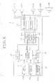
- FIG. 6 is a block diagram conceptually showing a configuration of a signal processing device 1 in accordance with a second preferred embodiment.
- the switching execution portion 14 may include an A/B switching portion 141 that performs switching regarding to the A-channel and the B-channel, and an ON/OFF switching portion 142 that is connected to a sub-woofer SW and switches between use and non-use of the sub-woofer SW serving as a speaker for super-low pitched sounds.
- the switching execution portion 14 can selectively switch a subject (e.g., only the A-channel, only the B-channel, the A-channel + the B-channel, the A-channel + the SW, the B-channel + the SW, or the A-channel + the B-channel + the SW) to be connected to the signal processing portion 16, among the A-channel, the B-channel, and the sub-woofer SW.
- a subject e.g., only the A-channel, only the B-channel, the A-channel + the B-channel, the A-channel + the SW, the B-channel + the SW, or the A-channel + the B-channel + the SW.
- the optimal setting Ia is obtained by measuring characteristics (speaker characteristics) of the speaker selected by the switching, and the obtained optimal setting Ia is stored in the storage portion 15 associating with the switching of the speaker.
- the characteristics (speaker characteristics) of the speaker selected by the switching can be optimized automatically, according to the switching of the speaker.
- the above-mentioned signal processing device 1 is not limited to the signal processing device that processes a two-channel audio signal, but may be a signal processing device that processes a multi-channel audio signal. In this case, speakers corresponding to the number of channels are connected to each of the A-channel and the B-channel.
- FIG. 7 (A) is a conceptual diagram showing the signal processing device 1 that processes a three-channel audio signal.
- FIG. 7 (A) shows the case where three speakers 21L, 21R, and 21C are connected to one of output channels of the signal processing device 1.
- switching this switching includes processing of selecting whether or not to include a signal to be supplied to speaker 21C in the output audio signal Sout outputted from the signal processing portion 16) between the case (see FIG. 7(A) ) where all three speakers are used and the case (see FIG. 7(B) ) where only two speakers 21L and 21R are used is also included in one aspect of the switching of the speaker in the present invention.
- FIG. 8 is a block diagram conceptually showing a configuration of a signal processing device 1 in accordance with a fourth preferred embodiment.
- the operation reception portion 17 may include a selection reception portion 172 that receives a selection about whether or not to perform the signal processing using the optimal setting Ia.
- the selection reception portion 172 receives, from a user, a selection instruction about whether or not to optimize speaker characteristics.
- FIG. 9 is a flowchart showing reproduction processing performed by the signal processing device 1 in the fourth preferred embodiment.
- the control portion 18 determines whether or not to optimize speaker characteristics according to the selection received by the selection reception portion 172 (Step S31).
- Step S31 When determining "optimized (Yes)" at Step S31, the control portion 18 perform the same processing (Steps S32 to S35, i.e., the processing that causes the signal processing portion 16 to read the optimal setting Ia) as that of Steps S21 to S24 in FIG. 4 .
- Step S36 the control portion 18 causes the signal processing portion 16 to read out the default setting Id from the storage portion 15 (Step S36).
- the signal processing portion 16 performs signal processing of the input audio signal Sin to be inputted (Step S37).
- the signal processing device 1 of the present preferred embodiment even after the optimal setting Ia is obtained in the signal processing device 1, it is possible to return to the default setting Id in which no changes have been made, and reproduce sounds. In other words, when sounds are reproduced, a user can select either an output of the optimized sound or an output of the default sound.
- a plurality of output channels which are not limited to two, may be included in the output portion 13.
- the switching execution portion 14 may switch a plurality of output channels among various combinations.
- the signal processing device 1 may have a configuration that sends the output audio signal Sout to the speaker, wirelessly.
- the signal processing device 1 may measure speaker characteristics for every speaker or for every output channel. Based on the measurement results, the signal processing device 1 may calculate the speaker characteristics and the optimal setting Ia, which correspond to various combinations of speakers or output channels.
- each configuration of the above-mentioned signal processing device 1 is not limited to the configuration that processes an audio signal, but may be applied to a configuration that processes various kinds of sound signals, such as a signal inputted through a microphone.
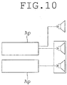
- FIG. 10 is a conceptual diagram showing another application example of the signal processing device 1.
- each configuration of the above-mentioned signal processing device 1 is also applicable to bi-amplifiers in which two amplifiers Ap are provided. Note that, each configuration of the signal processing device 1 may be applied to only one of two amplifiers Ap, or may be applied to both of them. Further, with respect to the two amplifiers Ap, switching may be performed between bi-amplifiers and single amplifier. Such switching is also included in one aspect of the switching of the speaker in the present invention.
Landscapes
- Physics & Mathematics (AREA)
- Engineering & Computer Science (AREA)
- Acoustics & Sound (AREA)
- Signal Processing (AREA)
- Health & Medical Sciences (AREA)
- General Health & Medical Sciences (AREA)
- Otolaryngology (AREA)
- Circuit For Audible Band Transducer (AREA)
- Stereophonic System (AREA)
Abstract
Description
- A preferred embodiment of the present invention relates to a technology for processing a signal to be supplied to a speaker.
- An AV (Audio Visual) amplifier may reproduce sound using all speakers connected to the amplifier. In addition, a HiFi (Hi Fidelity) amplifier may be able to use a speaker by switching speakers according to a sound source (classic or rock, for example) to be reproduced. Then, various methods have been proposed as technology to measure speaker characteristics and optimize the speaker characteristics using a measurement result (see
Patent Literature 1, for example). - Patent Literature 1: Unexamined Japanese Patent Publication No.
2015-84584 - However, even when the optimization technology in
Patent Literature 1 or the like is merely applied to an amplifier capable of switching speakers, a user will need to, for example, call a measurement result or to remeasure speaker characteristics after the speaker is switched, thereby forcing complicate operations on the user. - Accordingly, an object of one preferred embodiment of the present invention is to provide a signal processing device capable of optimizing characteristics of a speaker automatically, which is selected by switching, according to the switching of the speaker.
- A signal processing device according to a preferred embodiment of the present invention includes a switching reception portion, a storage portion, and a signal processing portion. The switching reception portion receives switching of a speaker serving as a supply destination of a signal. The storage portion stores an optimal setting, which is obtained by measuring characteristics (speaker characteristics) of the speaker selected by the switching, in association with the switching of the speaker. The signal processing portion reads out the optimal setting, which is associated with the switching received by the switching reception portion, from the storage portion, and uses the optimal setting to process the signal to be supplied to the speaker.
- According to one preferred embodiment of the present invention, the characteristics of the speaker selected by the switching can be optimized automatically, according to the switching of the speaker.
-
-
FIG. 1 is a block diagram conceptually showing a configuration of a signal processing device in accordance with a first preferred embodiment. -
FIG. 2 is a conceptual diagram showing an application example of the signal processing device. -
FIG. 3 is a flowchart showing processing to obtain an optimal setting, which is performed in the signal processing device. -
FIG. 4 is a flowchart showing reproduction processing performed in the signal processing device. -
FIG. 5 is a block diagram showing another application example of the signal processing device. -
FIG. 6 is a block diagram conceptually showing a configuration of a signal processing device in accordance with a second preferred embodiment. -
FIGS. 7(A) and (B) are conceptual diagrams showing a signal processing device in accordance with a third embodiment. -
FIG. 8 is a block diagram conceptually showing a configuration of a signal processing device in accordance with a fourth preferred embodiment. -
FIG. 9 is a flowchart showing reproduction processing performed in the signal processing device of the fourth preferred embodiment. -
FIG. 10 is a conceptual diagram showing another application example of the signal processing device. -
FIG. 1 is a block diagram conceptually showing a configuration of asignal processing device 1 in accordance with a first preferred embodiment. Further,FIG. 2 is a conceptual diagram showing an application example of thesignal processing device 1. As shown inFIG. 1 , thesignal processing device 1 includes aninput portion 11, an obtainingportion 12, anoutput portion 13, aswitching execution portion 14, astorage portion 15, asignal processing portion 16, anoperation reception portion 17, and acontrol portion 18 that controls these components collectively. - The
input portion 11 is an interface used for inputting an audio signal to thesignal processing device 1. Herein, the audio signal to be inputted to thesignal processing device 1 is an audio signal that is inputted from reading devices (not shown) such as a CD player, a DVD player, and an LD player. Hereinafter, the audio signal is referred to as "input audio signal Sin." - Specifically, the
input portion 11 has an interface that receives input of a digital audio signal, such as a HDMI (registered trademark) (High-Definition Multimedia Interface) or an S/PDIF (Sony Philips Digital Interface). A CD player or the like is connected to the interface. Theinput portion 11 further has an interface that receives input of an analog audio signal. An LD player or the like is connected to the interface. Note that, theinput portion 11 may contain an ADC (Analog to Digital Converter) that converts the inputted analog audio signal into a digital signal. - The obtaining
portion 12 is an interface that receives input of a sound signal to thesignal processing device 1. A microphone 3 (seeFIG. 2 ) is connected to the obtainingportion 12. A sound, which is inputted to themicrophone 3, is converted into a sound signal in themicrophone 3, and inputted to the obtainingportion 12. Note that, the sound signal may be an analog signal or may be a digital signal. In the case where the sound signal is an analog signal, the obtainingportion 12 may contain an ADC that converts the sound signal into a digital signal. - The
output portion 13 is an interface used for outputting the audio signal to a speaker. Herein, the audio signal, which is outputted to the speaker, is an audio signal that is subjected to signal processing in thesignal processing portion 16, as described later. Hereinafter, this audio signal is referred to as "output audio signal Sout." - In the present preferred embodiment, the
output portion 13 includes an A-channel and a B-channel as an output channel to which the speaker is connected. As an example, a pair ofspeakers speakers - The
switching execution portion 14 is a switch circuit, for example. Theswitching execution portion 14 switches to select one or both of the A-channel and the B-channel to be connected to thesignal processing portion 16, according to a switching execution instruction from thecontrol portion 18. Specifically, in theswitching execution portion 14, it is possible to execute switching to select only the A-channel, switching to select only the B-channel, and switching to select both the A-channel and the B-channel. - The
operation reception portion 17 is a user interface for receiving an operation instruction from a user. In the present preferred embodiment, theoperation reception portion 17 includes aswitching reception portion 171 that receives input of a switching instruction for switching the speaker from a user. Theswitching reception portion 171 is, for example, a changeover switch of a multi-stage type or a switching dial. Note that, theoperation reception portion 17 may include a display portion for presenting various information to a user. Further, theoperation reception portion 17 may include a reception portion that receives an operation signal from mobile terminals, such as a remote controller and a smart phone. Theoperation reception portion 17 may receive the operation signal, which is received by the reception portion, as an operation instruction. - When only the A-channel is selected, only a pair of
speakers speakers speakers - In other words, the speaker serving as a supply destination of the output audio signal Sout is switched by the
switching execution portion 14, according to the switching instruction received by theswitching reception portion 171. Such switching of the speaker includes a concept of an increase or decrease in the number of speakers. - Note that, the switching
execution portion 14 is not limited to a switch circuit, but may be an execution portion of thecontrol portion 18, which internally executes the switching (switch an output channel) of a speaker according to the switching instruction from a user. Such an execution portion can also be applied to the case where the output audio signal Sout is supplied to the speaker wirelessly from thesignal processing device 1. - The
storage portion 15 stores, as data, a default setting Id for achieving default signal processing. For instance, the default setting Id includes a setting for equalizing a left and right balance of the speaker, a setting for flattening frequency characteristics (F characteristics), and the like. As an example, the default setting Id includes various kinds of settings (setting of successive model specifications) that have been used without being greatly changed from successive models of amplifiers or the like. - The
storage portion 15 further stores the optimal setting Ia as data, in association with the switching (only the A-channel, only the B-channel, the A-channel + the B-channel) of the speaker. Herein, the optimal setting Ia corresponds to a measurement result obtained by measuring characteristics (speaker characteristics) of the speaker selected by the switching of the speaker. Specifically, the optimal setting Ia includes various kinds of settings (a setting of frequency characteristics (F characteristics), a setting of output timing (delay), a setting of a volume level, and the like) for optimizing the characteristics of the speaker according to the switching of the speaker. Note that, thesignal processing device 1 performs the following processing to obtain the optimal setting Ia. -
FIG. 3 is a flowchart showing processing for obtaining the optimal setting Ia. When thesignal processing device 1 detects that themicrophone 3 has been connected to the obtainingportion 12, or when an instruction of starting the measurement is received from a user, the processing is started. At this time, themicrophone 3 is installed at a listening position Pa by a user (seeFIG. 2 ). After the control processing is started, thesignal processing device 1 measures a test sound at the listening position Pa by using themicrophone 3, while emitting the test sound from the speaker selected by the switching of the speaker (Step S11). Next, thesignal processing device 1 analyzes the signal, which is obtained through the measurement, to derive various kinds of settings for optimizing the speaker characteristics (Step S12). Subsequently, by thesignal processing device 1, the various kinds of settings, which are derived at Step S12, are stored in thestorage portion 15 as the optimal setting Ia (Step S13). After that, when thesignal processing device 1 detects that themicrophone 3 has been removed from the obtaining portion 12 (Step S14), the processing for obtaining the optimal setting Ia is completed. Note that, the processing may be completed when this processing is performed for all switching operations and the optimal setting Ia corresponding to each switching is completely acquired. - The
signal processing portion 16 is a DSP (Digital Signal Processor) for example, and selectively reads out data related to any one of the default setting Id and the optimal setting Ia from thestorage portion 15 according to a read-out execution instruction from thecontrol portion 18. Then, thesignal processing portion 16 performs signal processing of the input audio signal Sin, using the read-out data. - If the default setting Id is used to process the input audio signal Sin, an output audio signal Sout on which the various kinds of settings in the default setting Id are reflected is obtained. This output audio signal Sout is supplied to the speaker, so that a default sound is outputted. Further, if the optimal setting Ia is used to process the input audio signal Sin, an output audio signal Sout on which the various kinds of settings in the optimal setting Ia are reflected is obtained. This output audio signal Sout is supplied to the speaker, so that an optimized sound is outputted.
- The
control portion 18, which controls thesignal processing device 1 collectively, is constituted by processing units such as a CPU (Central Processing Unit) and a microcomputer. In the present preferred embodiment, thecontrol portion 18 performs various kinds of processing, according to the operation instruction received by theoperation reception portion 17, or the like. Note that, the processing performed by thecontrol portion 18 is achieved by executing a program corresponding thereto through thecontrol portion 18. Such a program may be stored in a readable storage medium (e.g., a flash memory or the like), or may be stored in thestorage portion 15. -
FIG. 4 is a flowchart showing reproduction processing performed in thesignal processing device 1. The reproduction processing is started when electric power is supplied to the signal processing device 1 (at the time of power on), when themicrophone 3 is disconnected to the obtainingportion 12, when the switching of the speaker is performed, and the like. Note that, if electric power is supplied to thesignal processing device 1 in the state where themicrophone 3 is connected to the obtainingportion 12, the processing for obtaining the above-mentioned optimal setting Ia may be performed before the reproduction processing is performed. - When the reproduction processing is started, the
control portion 18 determines whether the optimal setting Ia associated with the switching received by the switchingreception portion 171 exists in thestorage portion 15 or not (Step S21). When determining "exist (Yes)" at Step S21, thecontrol portion 18 causes thesignal processing portion 16 to read out the optimal setting Ia associated with the switching received by the switchingreception portion 171, from the storage portion 15 (Step S22). On the other hand, when determining "not exist (No)" at Step S21, thecontrol portion 18 causes thesignal processing portion 16 to read out the default setting Id (Step S23). In that time, thecontrol portion 18 performs processing of notifying a user that the optimal setting Ia associated therewith does not exist in the storage portion 15 (Step S24). - Next, the
signal processing portion 16 performs signal processing of an input audio signal Sin to be inputted (Step S25). Specifically, thesignal processing portion 16 performs the signal processing of the input audio signal Sin, using the data (default setting Id or optimal setting Ia) which has been already read out fromstorage portion 15. The output audio signal Sout obtained by performing the signal processing is supplied to an output channel connected via the switchingexecution portion 14, as necessary. - According to such reproduction processing, in each switching of the speaker allowed to be received by the switching
reception portion 171, once the corresponding optimal setting Ia is obtained (seeFIG. 3 ), thecontrol portion 18 causes thesignal processing portion 16 to perform signal processing by using the same optimal setting Ia stored in thestorage portion 15, unless a change instruction (in the present preferred embodiment, connection of themicrophone 3 to the obtaining portion 12) for changing the optimal setting Ia or the like is received. Therefore, the characteristics (speaker characteristics) of the speaker selected by the switching can be optimized automatically, according to the switching of the speaker. - In this way, in the
signal processing device 1 of the present preferred embodiment, the optimal setting Ia obtained through the measurement channel can be preserved (stored in the storage portion 15) and called (read out from the storage portion 15) automatically. Therefore, complicated operations for optimizing the speaker characteristics can be eliminated when the speaker is switched. -
FIG. 5 is a block diagram showing another application example of thesignal processing device 1. As shown inFIG. 5 , each ofspeakers signal processing device 1, using a bi-wiring method.FIG. 5 shows the case where the tweeter TW is connected to the A-channel, and the woofer WF is connected to the B-channel. Switching of the speaker using such a bi-wiring method is also included in one aspect of the switching of the speaker in the present invention. -
FIG. 6 is a block diagram conceptually showing a configuration of asignal processing device 1 in accordance with a second preferred embodiment. As shown inFIG. 6 , the switchingexecution portion 14 may include an A/B switching portion 141 that performs switching regarding to the A-channel and the B-channel, and an ON/OFF switching portion 142 that is connected to a sub-woofer SW and switches between use and non-use of the sub-woofer SW serving as a speaker for super-low pitched sounds. - The switching
execution portion 14 can selectively switch a subject (e.g., only the A-channel, only the B-channel, the A-channel + the B-channel, the A-channel + the SW, the B-channel + the SW, or the A-channel + the B-channel + the SW) to be connected to thesignal processing portion 16, among the A-channel, the B-channel, and the sub-woofer SW. In this case as well, the optimal setting Ia is obtained by measuring characteristics (speaker characteristics) of the speaker selected by the switching, and the obtained optimal setting Ia is stored in thestorage portion 15 associating with the switching of the speaker. - In this
signal processing device 1 as well, the characteristics (speaker characteristics) of the speaker selected by the switching can be optimized automatically, according to the switching of the speaker. - The above-mentioned
signal processing device 1 is not limited to the signal processing device that processes a two-channel audio signal, but may be a signal processing device that processes a multi-channel audio signal. In this case, speakers corresponding to the number of channels are connected to each of the A-channel and the B-channel. -
FIG. 7 (A) is a conceptual diagram showing thesignal processing device 1 that processes a three-channel audio signal.FIG. 7 (A) shows the case where threespeakers signal processing device 1. In such asignal processing device 1, switching (this switching includes processing of selecting whether or not to include a signal to be supplied tospeaker 21C in the output audio signal Sout outputted from the signal processing portion 16) between the case (seeFIG. 7(A) ) where all three speakers are used and the case (seeFIG. 7(B) ) where only twospeakers -
FIG. 8 is a block diagram conceptually showing a configuration of asignal processing device 1 in accordance with a fourth preferred embodiment. As shown inFIG. 8 , in thesignal processing device 1, theoperation reception portion 17 may include aselection reception portion 172 that receives a selection about whether or not to perform the signal processing using the optimal setting Ia. In other words, theselection reception portion 172 receives, from a user, a selection instruction about whether or not to optimize speaker characteristics. -
FIG. 9 is a flowchart showing reproduction processing performed by thesignal processing device 1 in the fourth preferred embodiment. When the reproduction processing is started, thecontrol portion 18 determines whether or not to optimize speaker characteristics according to the selection received by the selection reception portion 172 (Step S31). - When determining "optimized (Yes)" at Step S31, the
control portion 18 perform the same processing (Steps S32 to S35, i.e., the processing that causes thesignal processing portion 16 to read the optimal setting Ia) as that of Steps S21 to S24 inFIG. 4 . On the other hand, when determining "not optimized (No)" at Step S31, thecontrol portion 18 causes thesignal processing portion 16 to read out the default setting Id from the storage portion 15 (Step S36). - After that, the
signal processing portion 16 performs signal processing of the input audio signal Sin to be inputted (Step S37). - According to the
signal processing device 1 of the present preferred embodiment, even after the optimal setting Ia is obtained in thesignal processing device 1, it is possible to return to the default setting Id in which no changes have been made, and reproduce sounds. In other words, when sounds are reproduced, a user can select either an output of the optimized sound or an output of the default sound. - In the above-mentioned
signal processing device 1, a plurality of output channels, which are not limited to two, may be included in theoutput portion 13. In such asignal processing device 1, the switchingexecution portion 14 may switch a plurality of output channels among various combinations. Further, thesignal processing device 1 may have a configuration that sends the output audio signal Sout to the speaker, wirelessly. - The
signal processing device 1 may measure speaker characteristics for every speaker or for every output channel. Based on the measurement results, thesignal processing device 1 may calculate the speaker characteristics and the optimal setting Ia, which correspond to various combinations of speakers or output channels. - Furthermore, each configuration of the above-mentioned
signal processing device 1 is not limited to the configuration that processes an audio signal, but may be applied to a configuration that processes various kinds of sound signals, such as a signal inputted through a microphone. -
FIG. 10 is a conceptual diagram showing another application example of thesignal processing device 1. As shown inFIG. 10 , each configuration of the above-mentionedsignal processing device 1 is also applicable to bi-amplifiers in which two amplifiers Ap are provided. Note that, each configuration of thesignal processing device 1 may be applied to only one of two amplifiers Ap, or may be applied to both of them. Further, with respect to the two amplifiers Ap, switching may be performed between bi-amplifiers and single amplifier. Such switching is also included in one aspect of the switching of the speaker in the present invention. - The description of the above-mentioned preferred embodiment is illustrative in all respects, and should not be construed to be restrictive. The scope of the present invention is indicated by the appended claims rather than by the above-mentioned preferred embodiments. Furthermore, the scope of the present invention is intended to include all modifications within the meaning and range equivalent to the scope of the claims.
-
- 1
- signal processing device
- 3
- microphone
- 11
- input portion
- 12
- obtaining portion
- 13
- output portion
- 14
- switching execution portion
- 15
- storage portion
- 16
- signal processing portion
- 17
- operation reception portion
- 18
- control portion
- 21L, 21R, and 21C
- speaker
- 22L and 22R
- speaker
- 141
- A/B switching portion
- 142
- ON/OFF switching portion
- 171
- switching reception portion
- 172
- selection reception portion
- Ap
- amplifier
- Ia
- optimal setting
- Id
- default setting
- Pa
- listening position
- TW
- tweeter
- WF
- woofer
- SW
- sub-woofer
- Sin
- input audio signal
- Sout
- output audio signal
Claims (5)
- A signal processing device comprising:a switching reception portion that receives switching of a speaker arranged as a supply destination of a signal;a storage portion that stores an optimal setting in association with the switching, the optimal setting being obtained by measuring characteristics of the speaker selected by the switching; anda signal processing portion that reads out the optimal setting from the storage portion and uses the optimal setting to process a signal to be supplied to the speaker, the optimal setting being associated with the switching received by the switching reception portion.
- The signal processing device according to claim 1, further comprising a plurality of output channels to which the speaker is connected, wherein the switching received by the switching reception portion includes a selection of any one of the output channels, and a selection of two or more of the output channels.
- The signal processing device according to claim 2, wherein the plurality of output channels include an output channel to which a speaker for high pitched sounds is connected, and an output channel to which a speaker for low pitched sounds is connected.
- The signal processing device according to any one of claims 1 to 3, wherein, once the optimal setting associated with the switching allowed to be received by the switching reception portion is obtained, the signal processing portion processes the signal by using the same optimal setting stored in the storage portion, unless an instruction for changing the optimal setting is received.
- The signal processing device according to any one of claims 1 to 4, further comprising a selection reception portion that receives a selection about whether or not to use the optimal setting in the signal processing, wherein, when the selection reception portion receives the selection in which the optimal setting is not used, the signal processing portion processes the signal by using a default setting.
Applications Claiming Priority (1)
| Application Number | Priority Date | Filing Date | Title |
|---|---|---|---|
| PCT/JP2017/011325 WO2018173131A1 (en) | 2017-03-22 | 2017-03-22 | Signal processing device |
Publications (3)
| Publication Number | Publication Date |
|---|---|
| EP3606101A1 true EP3606101A1 (en) | 2020-02-05 |
| EP3606101A4 EP3606101A4 (en) | 2020-11-18 |
| EP3606101B1 EP3606101B1 (en) | 2025-02-19 |
Family
ID=63585130
Family Applications (1)
| Application Number | Title | Priority Date | Filing Date |
|---|---|---|---|
| EP17901485.7A Active EP3606101B1 (en) | 2017-03-22 | 2017-03-22 | Signal processing device |
Country Status (4)
| Country | Link |
|---|---|
| US (2) | US10880651B2 (en) |
| EP (1) | EP3606101B1 (en) |
| JP (1) | JP6737395B2 (en) |
| WO (1) | WO2018173131A1 (en) |
Families Citing this family (2)
| Publication number | Priority date | Publication date | Assignee | Title |
|---|---|---|---|---|
| JP6787486B2 (en) * | 2017-04-12 | 2020-11-18 | ヤマハ株式会社 | Information processing equipment, information processing methods, and programs |
| JP7647219B2 (en) | 2021-03-24 | 2025-03-18 | ヤマハ株式会社 | Measurement method and device |
Family Cites Families (17)
| Publication number | Priority date | Publication date | Assignee | Title |
|---|---|---|---|---|
| JPH05344600A (en) * | 1992-06-12 | 1993-12-24 | Mitsubishi Electric Corp | Multi-channel audio playback device |
| JPH10136498A (en) * | 1996-10-24 | 1998-05-22 | Fuji Film Micro Device Kk | Automatic setting system for audio device |
| EP0866638B1 (en) * | 1997-03-10 | 2011-06-15 | Panasonic Corporation | Audiovisual amplifier |
| JP2000115900A (en) * | 1998-10-09 | 2000-04-21 | Nippon Columbia Co Ltd | Sound reproducing device |
| US6766025B1 (en) | 1999-03-15 | 2004-07-20 | Koninklijke Philips Electronics N.V. | Intelligent speaker training using microphone feedback and pre-loaded templates |
| JP2004096515A (en) * | 2002-09-02 | 2004-03-25 | Sony Corp | Audio output control device for in-vehicle audio / video equipment |
| JP4361354B2 (en) * | 2003-11-19 | 2009-11-11 | パイオニア株式会社 | Automatic sound field correction apparatus and computer program therefor |
| JP2006186571A (en) * | 2004-12-27 | 2006-07-13 | Clarion Co Ltd | Audio apparatus and control method thereof |
| JP4285469B2 (en) * | 2005-10-18 | 2009-06-24 | ソニー株式会社 | Measuring device, measuring method, audio signal processing device |
| JP2008306348A (en) * | 2007-06-06 | 2008-12-18 | Panasonic Corp | Digital broadcast receiver |
| JP5061864B2 (en) * | 2007-11-22 | 2012-10-31 | ヤマハ株式会社 | Television, audio signal supply apparatus and audio signal processing method |
| EP2375779A3 (en) * | 2010-03-31 | 2012-01-18 | Fraunhofer-Gesellschaft zur Förderung der Angewandten Forschung e.V. | Apparatus and method for measuring a plurality of loudspeakers and microphone array |
| JP2011259097A (en) * | 2010-06-07 | 2011-12-22 | Sony Corp | Audio signal processing device and audio signal processing method |
| JP5445574B2 (en) * | 2011-12-22 | 2014-03-19 | オンキヨー株式会社 | Channel divider, audio reproduction system including the same, and method for setting channel divider crossover frequency |
| US9462384B2 (en) * | 2012-09-05 | 2016-10-04 | Harman International Industries, Inc. | Nomadic device for controlling one or more portable speakers |
| WO2014148848A2 (en) * | 2013-03-21 | 2014-09-25 | 인텔렉추얼디스커버리 주식회사 | Audio signal size control method and device |
| JP6056842B2 (en) | 2014-12-26 | 2017-01-11 | ヤマハ株式会社 | Sound field control device |
-
2017
- 2017-03-22 WO PCT/JP2017/011325 patent/WO2018173131A1/en not_active Ceased
- 2017-03-22 EP EP17901485.7A patent/EP3606101B1/en active Active
- 2017-03-22 JP JP2019506591A patent/JP6737395B2/en active Active
-
2019
- 2019-09-18 US US16/574,482 patent/US10880651B2/en active Active
-
2020
- 2020-09-29 US US17/036,288 patent/US11399233B2/en active Active
Also Published As
| Publication number | Publication date |
|---|---|
| JP6737395B2 (en) | 2020-08-05 |
| US20210014618A1 (en) | 2021-01-14 |
| JPWO2018173131A1 (en) | 2019-11-14 |
| US11399233B2 (en) | 2022-07-26 |
| EP3606101B1 (en) | 2025-02-19 |
| EP3606101A4 (en) | 2020-11-18 |
| US20200015013A1 (en) | 2020-01-09 |
| US10880651B2 (en) | 2020-12-29 |
| WO2018173131A1 (en) | 2018-09-27 |
Similar Documents
| Publication | Publication Date | Title |
|---|---|---|
| BRPI1010444A2 (en) | audio system with portable audio enhancement device | |
| KR20180068202A (en) | Electronic apparatus and audio output apparatus consisting audio output system, and control method thereof | |
| KR20140146491A (en) | Audio System, Audio Device and Method for Channel Mapping Thereof | |
| US8861751B2 (en) | Audio processing apparatus | |
| US11399233B2 (en) | Signal processing device | |
| US7978865B2 (en) | Audio processing apparatus | |
| US11843921B2 (en) | In-sync digital waveform comparison to determine pass/fail results of a device under test (DUT) | |
| US12356160B2 (en) | Multi-channel audio system, multi-channel audio device, program, and multi-channel audio playback method | |
| US8494183B2 (en) | Audio processing apparatus | |
| US9066178B2 (en) | Audio processing apparatus | |
| US20230144494A1 (en) | Audio signal processing device, audio signal processing method, and recording medium | |
| JP5477402B2 (en) | Audio processing device | |
| EP3537728B1 (en) | Connection state determination system for speakers, acoustic device, and connection state determination method for speakers | |
| JP5304923B1 (en) | Audio processing device | |
| US20240015441A1 (en) | Av amplifier | |
| EP3611937A1 (en) | Information processing device, information processing method, and program | |
| TW202318888A (en) | Audio control device and method of controlling multi-channel sound system | |
| JP2009171364A (en) | Filter characteristic setting apparatus and method, audio system, and program | |
| Dawson | Lyngdorf TDAI-2170 stereo amplifier | |
| JPH06311579A (en) | Speaker connection deciding method for audio system | |
| KR20170038231A (en) | Apparatus and method for controlling mobile device in vehicle | |
| JP2013090303A (en) | Speech processing device and display device | |
| KR20060076558A (en) | Mobile phone charging device |
Legal Events
| Date | Code | Title | Description |
|---|---|---|---|
| STAA | Information on the status of an ep patent application or granted ep patent |
Free format text: STATUS: THE INTERNATIONAL PUBLICATION HAS BEEN MADE |
|
| PUAI | Public reference made under article 153(3) epc to a published international application that has entered the european phase |
Free format text: ORIGINAL CODE: 0009012 |
|
| STAA | Information on the status of an ep patent application or granted ep patent |
Free format text: STATUS: REQUEST FOR EXAMINATION WAS MADE |
|
| 17P | Request for examination filed |
Effective date: 20190920 |
|
| AK | Designated contracting states |
Kind code of ref document: A1 Designated state(s): AL AT BE BG CH CY CZ DE DK EE ES FI FR GB GR HR HU IE IS IT LI LT LU LV MC MK MT NL NO PL PT RO RS SE SI SK SM TR |
|
| AX | Request for extension of the european patent |
Extension state: BA ME |
|
| DAV | Request for validation of the european patent (deleted) | ||
| DAX | Request for extension of the european patent (deleted) | ||
| REG | Reference to a national code |
Ref country code: DE Ref legal event code: R079 Free format text: PREVIOUS MAIN CLASS: H04S0007000000 Ipc: H04R0003120000 |
|
| A4 | Supplementary search report drawn up and despatched |
Effective date: 20201021 |
|
| RIC1 | Information provided on ipc code assigned before grant |
Ipc: H04R 5/04 20060101ALI20201015BHEP Ipc: H04S 7/00 20060101ALI20201015BHEP Ipc: H04R 3/12 20060101AFI20201015BHEP Ipc: H04S 1/00 20060101ALI20201015BHEP |
|
| STAA | Information on the status of an ep patent application or granted ep patent |
Free format text: STATUS: EXAMINATION IS IN PROGRESS |
|
| 17Q | First examination report despatched |
Effective date: 20210713 |
|
| GRAP | Despatch of communication of intention to grant a patent |
Free format text: ORIGINAL CODE: EPIDOSNIGR1 |
|
| STAA | Information on the status of an ep patent application or granted ep patent |
Free format text: STATUS: GRANT OF PATENT IS INTENDED |
|
| INTG | Intention to grant announced |
Effective date: 20240923 |
|
| GRAS | Grant fee paid |
Free format text: ORIGINAL CODE: EPIDOSNIGR3 |
|
| GRAA | (expected) grant |
Free format text: ORIGINAL CODE: 0009210 |
|
| STAA | Information on the status of an ep patent application or granted ep patent |
Free format text: STATUS: THE PATENT HAS BEEN GRANTED |
|
| AK | Designated contracting states |
Kind code of ref document: B1 Designated state(s): AL AT BE BG CH CY CZ DE DK EE ES FI FR GB GR HR HU IE IS IT LI LT LU LV MC MK MT NL NO PL PT RO RS SE SI SK SM TR |
|
| REG | Reference to a national code |
Ref country code: GB Ref legal event code: FG4D |
|
| REG | Reference to a national code |
Ref country code: CH Ref legal event code: EP |
|
| REG | Reference to a national code |
Ref country code: DE Ref legal event code: R096 Ref document number: 602017087936 Country of ref document: DE |
|
| REG | Reference to a national code |
Ref country code: IE Ref legal event code: FG4D |
|
| REG | Reference to a national code |
Ref country code: NL Ref legal event code: MP Effective date: 20250219 |
|
| PG25 | Lapsed in a contracting state [announced via postgrant information from national office to epo] |
Ref country code: RS Free format text: LAPSE BECAUSE OF FAILURE TO SUBMIT A TRANSLATION OF THE DESCRIPTION OR TO PAY THE FEE WITHIN THE PRESCRIBED TIME-LIMIT Effective date: 20250519 |
|
| PG25 | Lapsed in a contracting state [announced via postgrant information from national office to epo] |
Ref country code: FI Free format text: LAPSE BECAUSE OF FAILURE TO SUBMIT A TRANSLATION OF THE DESCRIPTION OR TO PAY THE FEE WITHIN THE PRESCRIBED TIME-LIMIT Effective date: 20250219 |
|
| PG25 | Lapsed in a contracting state [announced via postgrant information from national office to epo] |
Ref country code: PL Free format text: LAPSE BECAUSE OF FAILURE TO SUBMIT A TRANSLATION OF THE DESCRIPTION OR TO PAY THE FEE WITHIN THE PRESCRIBED TIME-LIMIT Effective date: 20250219 |
|
| PG25 | Lapsed in a contracting state [announced via postgrant information from national office to epo] |
Ref country code: ES Free format text: LAPSE BECAUSE OF FAILURE TO SUBMIT A TRANSLATION OF THE DESCRIPTION OR TO PAY THE FEE WITHIN THE PRESCRIBED TIME-LIMIT Effective date: 20250219 |
|
| REG | Reference to a national code |
Ref country code: LT Ref legal event code: MG9D |
|
| PG25 | Lapsed in a contracting state [announced via postgrant information from national office to epo] |
Ref country code: IS Free format text: LAPSE BECAUSE OF FAILURE TO SUBMIT A TRANSLATION OF THE DESCRIPTION OR TO PAY THE FEE WITHIN THE PRESCRIBED TIME-LIMIT Effective date: 20250619 Ref country code: NO Free format text: LAPSE BECAUSE OF FAILURE TO SUBMIT A TRANSLATION OF THE DESCRIPTION OR TO PAY THE FEE WITHIN THE PRESCRIBED TIME-LIMIT Effective date: 20250519 |
|
| PG25 | Lapsed in a contracting state [announced via postgrant information from national office to epo] |
Ref country code: NL Free format text: LAPSE BECAUSE OF FAILURE TO SUBMIT A TRANSLATION OF THE DESCRIPTION OR TO PAY THE FEE WITHIN THE PRESCRIBED TIME-LIMIT Effective date: 20250219 |
|
| PG25 | Lapsed in a contracting state [announced via postgrant information from national office to epo] |
Ref country code: HR Free format text: LAPSE BECAUSE OF FAILURE TO SUBMIT A TRANSLATION OF THE DESCRIPTION OR TO PAY THE FEE WITHIN THE PRESCRIBED TIME-LIMIT Effective date: 20250219 |
|
| PG25 | Lapsed in a contracting state [announced via postgrant information from national office to epo] |
Ref country code: LV Free format text: LAPSE BECAUSE OF FAILURE TO SUBMIT A TRANSLATION OF THE DESCRIPTION OR TO PAY THE FEE WITHIN THE PRESCRIBED TIME-LIMIT Effective date: 20250219 Ref country code: PT Free format text: LAPSE BECAUSE OF FAILURE TO SUBMIT A TRANSLATION OF THE DESCRIPTION OR TO PAY THE FEE WITHIN THE PRESCRIBED TIME-LIMIT Effective date: 20250620 |
|
| PG25 | Lapsed in a contracting state [announced via postgrant information from national office to epo] |
Ref country code: GR Free format text: LAPSE BECAUSE OF FAILURE TO SUBMIT A TRANSLATION OF THE DESCRIPTION OR TO PAY THE FEE WITHIN THE PRESCRIBED TIME-LIMIT Effective date: 20250520 Ref country code: BG Free format text: LAPSE BECAUSE OF FAILURE TO SUBMIT A TRANSLATION OF THE DESCRIPTION OR TO PAY THE FEE WITHIN THE PRESCRIBED TIME-LIMIT Effective date: 20250219 |
|
| REG | Reference to a national code |
Ref country code: AT Ref legal event code: MK05 Ref document number: 1769519 Country of ref document: AT Kind code of ref document: T Effective date: 20250219 |
|
| PG25 | Lapsed in a contracting state [announced via postgrant information from national office to epo] |
Ref country code: SE Free format text: LAPSE BECAUSE OF FAILURE TO SUBMIT A TRANSLATION OF THE DESCRIPTION OR TO PAY THE FEE WITHIN THE PRESCRIBED TIME-LIMIT Effective date: 20250219 |
|
| PG25 | Lapsed in a contracting state [announced via postgrant information from national office to epo] |
Ref country code: SM Free format text: LAPSE BECAUSE OF FAILURE TO SUBMIT A TRANSLATION OF THE DESCRIPTION OR TO PAY THE FEE WITHIN THE PRESCRIBED TIME-LIMIT Effective date: 20250219 |
|
| PG25 | Lapsed in a contracting state [announced via postgrant information from national office to epo] |
Ref country code: DK Free format text: LAPSE BECAUSE OF FAILURE TO SUBMIT A TRANSLATION OF THE DESCRIPTION OR TO PAY THE FEE WITHIN THE PRESCRIBED TIME-LIMIT Effective date: 20250219 |
|
| PG25 | Lapsed in a contracting state [announced via postgrant information from national office to epo] |
Ref country code: IT Free format text: LAPSE BECAUSE OF FAILURE TO SUBMIT A TRANSLATION OF THE DESCRIPTION OR TO PAY THE FEE WITHIN THE PRESCRIBED TIME-LIMIT Effective date: 20250219 |
|
| PG25 | Lapsed in a contracting state [announced via postgrant information from national office to epo] |
Ref country code: AT Free format text: LAPSE BECAUSE OF FAILURE TO SUBMIT A TRANSLATION OF THE DESCRIPTION OR TO PAY THE FEE WITHIN THE PRESCRIBED TIME-LIMIT Effective date: 20250219 |
|
| PG25 | Lapsed in a contracting state [announced via postgrant information from national office to epo] |
Ref country code: EE Free format text: LAPSE BECAUSE OF FAILURE TO SUBMIT A TRANSLATION OF THE DESCRIPTION OR TO PAY THE FEE WITHIN THE PRESCRIBED TIME-LIMIT Effective date: 20250219 Ref country code: CZ Free format text: LAPSE BECAUSE OF FAILURE TO SUBMIT A TRANSLATION OF THE DESCRIPTION OR TO PAY THE FEE WITHIN THE PRESCRIBED TIME-LIMIT Effective date: 20250219 |
|
| REG | Reference to a national code |
Ref country code: CH Ref legal event code: H13 Free format text: ST27 STATUS EVENT CODE: U-0-0-H10-H13 (AS PROVIDED BY THE NATIONAL OFFICE) Effective date: 20251023 |
|
| PG25 | Lapsed in a contracting state [announced via postgrant information from national office to epo] |
Ref country code: RO Free format text: LAPSE BECAUSE OF FAILURE TO SUBMIT A TRANSLATION OF THE DESCRIPTION OR TO PAY THE FEE WITHIN THE PRESCRIBED TIME-LIMIT Effective date: 20250219 |
|
| PG25 | Lapsed in a contracting state [announced via postgrant information from national office to epo] |
Ref country code: SK Free format text: LAPSE BECAUSE OF FAILURE TO SUBMIT A TRANSLATION OF THE DESCRIPTION OR TO PAY THE FEE WITHIN THE PRESCRIBED TIME-LIMIT Effective date: 20250219 |
|
| PG25 | Lapsed in a contracting state [announced via postgrant information from national office to epo] |
Ref country code: LU Free format text: LAPSE BECAUSE OF NON-PAYMENT OF DUE FEES Effective date: 20250322 |
|
| REG | Reference to a national code |
Ref country code: DE Ref legal event code: R097 Ref document number: 602017087936 Country of ref document: DE |
|
| REG | Reference to a national code |
Ref country code: BE Ref legal event code: MM Effective date: 20250331 |
|
| PG25 | Lapsed in a contracting state [announced via postgrant information from national office to epo] |
Ref country code: MC Free format text: LAPSE BECAUSE OF FAILURE TO SUBMIT A TRANSLATION OF THE DESCRIPTION OR TO PAY THE FEE WITHIN THE PRESCRIBED TIME-LIMIT Effective date: 20250219 |
|
| PLBE | No opposition filed within time limit |
Free format text: ORIGINAL CODE: 0009261 |
|
| STAA | Information on the status of an ep patent application or granted ep patent |
Free format text: STATUS: NO OPPOSITION FILED WITHIN TIME LIMIT |
|
| PG25 | Lapsed in a contracting state [announced via postgrant information from national office to epo] |
Ref country code: FR Free format text: LAPSE BECAUSE OF NON-PAYMENT OF DUE FEES Effective date: 20250419 |
|
| PG25 | Lapsed in a contracting state [announced via postgrant information from national office to epo] |
Ref country code: BE Free format text: LAPSE BECAUSE OF NON-PAYMENT OF DUE FEES Effective date: 20250331 |
|
| PG25 | Lapsed in a contracting state [announced via postgrant information from national office to epo] |
Ref country code: CH Free format text: LAPSE BECAUSE OF NON-PAYMENT OF DUE FEES Effective date: 20250331 |
|
| PG25 | Lapsed in a contracting state [announced via postgrant information from national office to epo] |
Ref country code: IE Free format text: LAPSE BECAUSE OF NON-PAYMENT OF DUE FEES Effective date: 20250322 |
|
| 26N | No opposition filed |
Effective date: 20251120 |
|
| GBPC | Gb: european patent ceased through non-payment of renewal fee |
Effective date: 20250519 |
|
| PG25 | Lapsed in a contracting state [announced via postgrant information from national office to epo] |
Ref country code: GB Free format text: LAPSE BECAUSE OF NON-PAYMENT OF DUE FEES Effective date: 20250519 |
|
| PGFP | Annual fee paid to national office [announced via postgrant information from national office to epo] |
Ref country code: DE Payment date: 20260319 Year of fee payment: 10 |