EP3606091A1 - Sound pickup device and sound pickup method - Google Patents
Sound pickup device and sound pickup method Download PDFInfo
- Publication number
- EP3606091A1 EP3606091A1 EP17901745.4A EP17901745A EP3606091A1 EP 3606091 A1 EP3606091 A1 EP 3606091A1 EP 17901745 A EP17901745 A EP 17901745A EP 3606091 A1 EP3606091 A1 EP 3606091A1
- Authority
- EP
- European Patent Office
- Prior art keywords
- sound pickup
- microphone
- sound
- pickup device
- signal
- Prior art date
- Legal status (The legal status is an assumption and is not a legal conclusion. Google has not performed a legal analysis and makes no representation as to the accuracy of the status listed.)
- Withdrawn
Links
Images








Classifications
-
- H—ELECTRICITY
- H04—ELECTRIC COMMUNICATION TECHNIQUE
- H04R—LOUDSPEAKERS, MICROPHONES, GRAMOPHONE PICK-UPS OR LIKE ACOUSTIC ELECTROMECHANICAL TRANSDUCERS; ELECTRIC HEARING AIDS; PUBLIC ADDRESS SYSTEMS
- H04R1/00—Details of transducers, loudspeakers or microphones
- H04R1/20—Arrangements for obtaining desired frequency or directional characteristics
- H04R1/32—Arrangements for obtaining desired frequency or directional characteristics for obtaining desired directional characteristic only
- H04R1/34—Arrangements for obtaining desired frequency or directional characteristics for obtaining desired directional characteristic only by using a single transducer with sound reflecting, diffracting, directing or guiding means
- H04R1/342—Arrangements for obtaining desired frequency or directional characteristics for obtaining desired directional characteristic only by using a single transducer with sound reflecting, diffracting, directing or guiding means for microphones
-
- H—ELECTRICITY
- H04—ELECTRIC COMMUNICATION TECHNIQUE
- H04R—LOUDSPEAKERS, MICROPHONES, GRAMOPHONE PICK-UPS OR LIKE ACOUSTIC ELECTROMECHANICAL TRANSDUCERS; ELECTRIC HEARING AIDS; PUBLIC ADDRESS SYSTEMS
- H04R1/00—Details of transducers, loudspeakers or microphones
- H04R1/20—Arrangements for obtaining desired frequency or directional characteristics
- H04R1/32—Arrangements for obtaining desired frequency or directional characteristics for obtaining desired directional characteristic only
- H04R1/40—Arrangements for obtaining desired frequency or directional characteristics for obtaining desired directional characteristic only by combining a number of identical transducers
-
- G—PHYSICS
- G10—MUSICAL INSTRUMENTS; ACOUSTICS
- G10K—SOUND-PRODUCING DEVICES; METHODS OR DEVICES FOR PROTECTING AGAINST, OR FOR DAMPING, NOISE OR OTHER ACOUSTIC WAVES IN GENERAL; ACOUSTICS NOT OTHERWISE PROVIDED FOR
- G10K11/00—Methods or devices for transmitting, conducting or directing sound in general; Methods or devices for protecting against, or for damping, noise or other acoustic waves in general
- G10K11/16—Methods or devices for protecting against, or for damping, noise or other acoustic waves in general
- G10K11/175—Methods or devices for protecting against, or for damping, noise or other acoustic waves in general using interference effects; Masking sound
- G10K11/178—Methods or devices for protecting against, or for damping, noise or other acoustic waves in general using interference effects; Masking sound by electro-acoustically regenerating the original acoustic waves in anti-phase
- G10K11/1785—Methods, e.g. algorithms; Devices
-
- H—ELECTRICITY
- H03—ELECTRONIC CIRCUITRY
- H03G—CONTROL OF AMPLIFICATION
- H03G3/00—Gain control in amplifiers or frequency changers
- H03G3/20—Automatic control
- H03G3/30—Automatic control in amplifiers having semiconductor devices
- H03G3/3005—Automatic control in amplifiers having semiconductor devices in amplifiers suitable for low-frequencies, e.g. audio amplifiers
-
- H—ELECTRICITY
- H03—ELECTRONIC CIRCUITRY
- H03G—CONTROL OF AMPLIFICATION
- H03G3/00—Gain control in amplifiers or frequency changers
- H03G3/20—Automatic control
- H03G3/30—Automatic control in amplifiers having semiconductor devices
- H03G3/3005—Automatic control in amplifiers having semiconductor devices in amplifiers suitable for low-frequencies, e.g. audio amplifiers
- H03G3/301—Automatic control in amplifiers having semiconductor devices in amplifiers suitable for low-frequencies, e.g. audio amplifiers the gain being continuously variable
-
- H—ELECTRICITY
- H04—ELECTRIC COMMUNICATION TECHNIQUE
- H04R—LOUDSPEAKERS, MICROPHONES, GRAMOPHONE PICK-UPS OR LIKE ACOUSTIC ELECTROMECHANICAL TRANSDUCERS; ELECTRIC HEARING AIDS; PUBLIC ADDRESS SYSTEMS
- H04R1/00—Details of transducers, loudspeakers or microphones
- H04R1/20—Arrangements for obtaining desired frequency or directional characteristics
- H04R1/32—Arrangements for obtaining desired frequency or directional characteristics for obtaining desired directional characteristic only
- H04R1/40—Arrangements for obtaining desired frequency or directional characteristics for obtaining desired directional characteristic only by combining a number of identical transducers
- H04R1/406—Arrangements for obtaining desired frequency or directional characteristics for obtaining desired directional characteristic only by combining a number of identical transducers microphones
-
- H—ELECTRICITY
- H04—ELECTRIC COMMUNICATION TECHNIQUE
- H04R—LOUDSPEAKERS, MICROPHONES, GRAMOPHONE PICK-UPS OR LIKE ACOUSTIC ELECTROMECHANICAL TRANSDUCERS; ELECTRIC HEARING AIDS; PUBLIC ADDRESS SYSTEMS
- H04R3/00—Circuits for transducers
- H04R3/005—Circuits for transducers for combining the signals of two or more microphones
Definitions
- One preferred embodiment of the present invention relates to a sound pickup device that acquires sounds of a sound source by using a microphone, and a sound pickup method.
- the sound-source position determining device described in Patent literature 1 or the technique of Non-Patent Literature 1 is known, for example.
- the sound-source position determining device of Patent Literature 1 calculates an arrival time difference between a direct sound and a reflected sound. For instance, the shorter a distance between a microphone and a sound source is, the faster the direct sound reaches the microphone. This increases the arrival time difference between the direct sound and the reflected sound. Conversely, the arrival time difference between a direct sound and an indirect sound is reduced as the distance between the microphone and the sound source becomes long.
- Non-Patent Literature 1 a position of the sound source is estimated by using the fact that an arrival time difference occurs between a right ear and a left ear.
- Patent Literature 1 Unexamined Japanese Patent Publication No. 2013-170936
- Non-Patent literature 1 R. F. Lyon. A computational model of binaural localization and separation. In Proceedings of the International Conference on Acoustics, Speech and Signal Processing, pages 1148-1151, 1983
- the arrival time is varied depending on environment, such as a size of a room. Accordingly, in the method of using the reflected sound, like Patent Literature 1, the environment is likely to cause an error in a value of the distance to be estimated. Further, in the technique of Non-Patent literature 1, sounds coming from the same direction have the same arrival time difference. This makes it difficult to estimate the distance.
- One preferred embodiment of the present invention aims to provide a sound pickup device that acquires sounds of a sound source appropriately without depending on environment such as a reflected sound, and a sound pickup method.
- a sound pickup device includes a microphone, an acoustic obstacle, a signal processing portion, and a gain control portion.
- the acoustic obstacle blocks sound pickup in a predetermined range with respect to the microphone.
- the signal processing portion splits a sound pickup signal of the microphone into a plurality of sound pickup signals, and subjects at least one sound pickup signal among the plurality of sound pickup signals to band limitation processing.
- the gain control portion compares characteristic amounts of the plurality of sound pickup signals including the sound pickup signal after being subjected to the band limitation processing by the signal processing portion, and controls a gain of the microphone in accordance with a result of comparing the characteristic amounts.
- the sound pickup device includes a first microphone, a second microphone, an acoustic obstacle, and a gain control portion.
- the acoustic obstacle blocks sound pickup in a predetermined range with respect to the first microphone.
- the gain control portion compares characteristic amounts of a sound pickup signal of the first microphone and a sound pickup signal of the second microphone, and controls a gain of the first microphone or the second microphone in accordance with a result of comparing the characteristic amounts.
- sounds of a sound source can be acquired appropriately, without depending on environment such as a reflected sound.
- FIG. 1 is a schematic view showing a structure of a sound pickup device 1 in accordance with a first preferred embodiment.
- a main structure in accordance with sound pickup is shown, and the other structure is not shown.
- the sound pickup device 1 includes a housing 50 with a cylindrical shape, and a microphone 10.
- the housing 50 is made of metal or resin, and has sound insulating properties.
- the housing 50 is an example of an acoustic obstacle of the present invention.
- a center portion of the housing 50 is opened acoustically.
- the microphone 10 is disposed in a cylinder of the housi5g 50.
- the microphone 10 is hidden by the housing 50 in a horizontal direction of an installation surface (e.g., top of a desk) on which the sound pickup device 1 is installed.
- the microphone 10 is acoustically opened from the housing 50 at a predetermined angle or more with respect to the horizontal direction of the installation surface on which the sound pickup device 1 is installed.
- the housing 50 is installed on a desk 70, as shown in FIGS. 2(A) and 2(B) .
- a voice emitted from a speaker 5 located in a position close to the sound pickup device 1 reaches the microphone 10 directly, without being blocked by the housing 50.
- a voice emitted from a speaker 7 located in a position remote from the sound pickup device 1 is blocked by the housing 50.
- the voice emitted from the speaker 7 located in a position remote from the sound pickup device 1 only a component (mainly a low-band component) traveling around the housing 50 reaches the microphone 10.
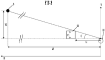
- FIG. 3 is a view showing a positional relationship between the microphone 10, the housing 50 serving as an acoustic obstacle, and a speaker (sound source) S.
- a sound of the sound source S is blocked by the housing 50 at a predetermined angle ⁇ or less with respect to an upper surface of the desk (horizontal direction L).
- a speaker is located within a range whose distance from a closest position to a desk is approximately 100 cm. Accordingly, a ratio (L1/V1) of L1 to V1 is desired to be set to approximately a value ranging from 1 to 3.33.
- L1/V1 L1/V1
- a voice in a range having a radius of approximately 30 cm to 100 cm reaches the microphone 10 without being blocked by the housing 50, and a voice out of the range having a radius of approximately 30 cm to 100 cm is blocked by the housing 50.
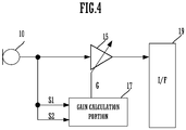
- FIG. 4 is a block diagram of the sound pickup device 1.
- the sound pickup device 1 includes the microphone 10, a gain adjustment portion 15, a gain calculation portion 17, and an interface (I/F) 19.
- a sound pickup signal which is the voice acquired by the microphone 10, is subjected to gain adjustment in the gain adjustment portion 15 and inputted to the I/F 19.
- the I/F 19 is, for example, a communication I/F and transmits the sound pickup signal to an external device (remote area).
- the I/F 19 outputs the sound pickup signal to a storage portion (not shown).
- the storage portion records the sound pickup signal, which is acquired by the microphone 10, as recording data.
- the gain calculation portion 17 sets a gain of the gain adjustment portion 15.
- a gain control portion in the present invention is constituted by the gain adjustment portion 15 and the gain calculation portion 17.
- the sound pickup signal is inputted to the gain calculation portion 17.
- the sound pickup signal is split into a plurality of sound pickup signals (a sound pickup signal S1 and a sound pickup signal S2).
- the function of the gain adjustment portion 15 and the gain calculation portion 17 can be achieved by a common information processor, such as a personal computer.
- the information processor reads out a program stored in a storage medium, such as a flash memory, and executes the program, thereby achieving the function of the gain adjustment portion 15 and the gain calculation portion 17.
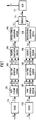
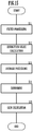
- FIG. 5 is a block diagram (functional block diagram) showing a configuration of the gain calculation portion 17. Further, FIG. 15 is a flowchart showing an operation of the gain calculation portion 17.
- the gain calculation portion 17 includes a filter portion (Filter) 171A, a filter portion 171B, an absolute value calculation portion (Absolute) 172A, an absolute value calculation portion 172B, an average processing portion (Average) 173A, an average processing portion 173B, a comparing portion (Compare) 174, and a gain calculation portion (Gain) 175.
- the sound pickup signal S1 is inputted to the filter portion 171A, and the sound pickup signal S2 is inputted to the filter portion 171B.
- the filter portion 171A and the filter portion 171B each perform band limitation processing (S11).
- the filter portion 171A and the filter portion 171B perform processing of extracting a band in which a difference in acoustic characteristic amount occurs between the voice emitted from a speaker located in a position close to the sound pickup device 1 and the voice emitted from a speaker located in a position remote from the sound pickup device 1.
- the filter portion 171A is low-band limitation processing (high-pass filter), and the filter portion 171B is all-band pass processing (all-pass filter).
- the voice emitted from the speaker located in a position close to the sound pickup device 1 reaches the microphone 10, without being blocked by the housing 50.
- a component (mainly low-band component) traveling around the housing 50 reaches the microphone 10. Accordingly, in the voice emitted from the speaker located in a position close to the sound pickup device 1, a significant level difference does not occur between an output signal of the filter portion 171B and an output signal of the filter portion 171A.
- An output signal (sound pickup signal) S1-1 of the filter portion 171A is subjected to absolute value processing in the absolute value calculation portion 172A and calculated as a power value S1-2 (S12).
- the calculated power value is averaged over a predetermined time range in the average processing portion 173A to obtain an average power value S1-3 (S13).
- An output signal (sound pickup signal) S2-1 of the filter portion 171B is subjected to absolute value processing in the absolute value calculation portion 172B and calculated as a power value S2-2 (S12).
- the calculated power value is averaged over a predetermined time range in the average processing portion 173B to obtain an average power value S2-3 (S13) .
- the comparing portion 174 calculates a value R (S14).
- the value R is obtained by dividing an output value (average power value) S1-3 of the average processing portion 173A by an output value (average power value) S2-3 of the average processing portion 173B.
- the division is an example of a method for comparing the acoustic characteristic amount.
- the output signal of the average processing portion 173A is subtracted from the output signal of the average processing portion 173B, and the resulting differential value may be defined as the value R, for example.
- FIG. 6 is a view showing a relationship between a distance and a level of each sound pickup signal.
- a level (e.g., power value) of the sound pickup signal S2-1 decreases as a distance from the microphone 10 becomes long.
- the arrival of voice is blocked by the housing 50.
- the degree of reduction in a level of the sound pickup signal S2-1 is increased as the distance from the microphone 10 becomes long.
- the sound pickup signal S1-1 is decreased as the distance from microphone 10 becomes long, like the sound pickup signal S2-1.
- the arrival of voice is blocked by the housing 50, and the low-band component, which is easy to travel around the microphone 10, is cut off. Therefore, the degree of reduction in a level of the sound pickup signal S1-1 is further increased as the distance from the microphone 10 becomes long. Consequently, the value R is reduced significantly, when the sound source is located at a position farther than the distance L2.
- FIG. 7 is a block diagram (functional block diagram) showing a configuration of the gain calculation portion 17 when the inverse of variance of voice rising time in a different frequency band is used as the characteristic amount.
- the gain calculation portion 17 includes a filter portion 171A, a filter portion 171B, a band division portion 182A, a band division portion 182B, a rise time detection portion 183A, a rise time detection portion 183B, a variance calculation portion 184A, a variance calculation portion 184B, an inverse number calculation portion 185A, an inverse number calculation portion 185B, a comparing portion 174, and a gain calculation portion 175.
- an output signal S1-1 of the filter portion 171A is inputted to the band division portion 182A, and then divided into still fine bands to obtain a signal S1-4.
- the signal S1-4 is inputted to the rise time detection portion 182A.
- An output signal S2-1 of the filter portion 171B is inputted to band division portion 182B, and then divided into still fine bands to obtain a signal S2-4.
- the signal S2-4 is inputted to the rise time detection portion 182B.
- the rise time detection portion 182A calculates the time when a level of the signal S1-4 exceeds a given threshold, and outputs it as a time value S1-5.
- the time value S1-5 is inputted to the variance calculation portion 184A.
- the rise time detection portion 182B calculates the time when a level of the signal S2-4 exceeds a given threshold, and outputs it as a time value S2-5.
- the time value S2-5 is inputted to the variance calculation portion 184B.
- the variance calculation portion 184A calculates a variance value of the time value S1-5 related to the band, and outputs it as a variance value S1-6.
- the variance value S1-6 is converted into an inverse number S1-7 through the inverse number calculation portion 185A.
- the variance calculation portion 184B calculates a variance value of the time value S2-5 related to the band, and outputs it as a variance value S2-6.
- the variance value S2-6 is converted into an inverse number S2-7 through the inverse number calculation portion 185B.
- the comparing portion 174 divides the inverse number S1-7 by the inverse number S2-7 to output a value R.
- FIG. 8 is a view showing a relationship between a distance, and the inverse number S1-7 and the inverse number S2-7. Since an all-pass filter is applied in the filter portion 171A, the output signal S1-1 includes a low-band component, which is hard to be affected by an obstacle. Accordingly, in the signal S1-1, a direct sound is dominant rather than an indirect sound due to reflection in a room or the like, even if a position of the sound source is closer or farther than the distance L2.
- the time value S1-5 which indicates the time when a sound wave reaches, is almost the same for every frequency, because the direct sound travels on the shortest path from the sound source to the microphone 10. Therefore, the variance value S1-6, which indicates variance of rise time, is reduced, so that the inverse number S1-7, which indicates an inverse of vairance of rise time, has a large value.
- the gain calculation portion 175 calculates a gain G according to the value R (S15).
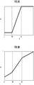
- FIG. 9(A) is a view showing an example of a gain table. As shown in FIG. 9(A) , in the gain table, when the value R is more than or equal to a predetermined value R1, no attenuation occurs. From the predetermined value R1 to R2, the gain G is set to be attenuated as the value R is reduced. When the value R is smaller than R2, the minimum gain value is maintained.
- the value R is decreased according to an increase in the distance.
- the predetermined value R1 and the predetermined value R2 may be set optionally, but the predetermined value R1 is set according to the maximum range in which sound pickup is desired to be performed without being attenuated. For instance, a ratio (L1/V1) of L1 to V1 is assumed to be 1. When a position of the sound source is farther than a radius of approximately 30 cm, the value R is reduced. However, if the predetermined value R1 is set to a value R obtained when the distance is approximately 40 cm, a sound can be picked up without being attenuated, up to a radius of approximately 40 cm.
- the predetermined value R2 is set according to the minimum range in which the attenuation is desired. For instance, if the predetermined value R2 is set to a value R obtained when the distance is 100 cm, sound pickup will scarcely be performed when the distance is more than or equal to 100 cm. When the distance is closer than 100 cm, the gain gradually increases, so that sound pickup is performed.
- the current position of the sound source as a reference, a sound in a range closer to the microphone 10 than the position of the sound source is picked up, and a sound farther than the position of the sound source is not picked up.
- FIG. 9(A) is an aspect in which the gain decreases rapidly from a predetermined distance (e.g., 30 cm) and the sound source whose position is farther than a predetermined distance (e.g., 100 cm) is scarcely picked up, which is similar to the function of a limiter.
- a predetermined distance e.g., 30 cm
- various kinds of aspects can be considered as the gain table, as shown in FIG. 9(B) .
- FIG. 9(B) is an aspect in which the gain gradually decreases according to the distance, the degree of decrease in the gain is increased from a predetermined distance (e.g., 30 cm), and the gain gradually decreases again at more than or equal to a predetermined distance (e.g., 100 cm), which is similar to the function of a compressor.
- the sound pickup device 1 in the present preferred embodiment has an aspect that picks up a sound of the sound source whose distance from the microphone 10 is within a predetermined range, and does not pick up a sound out of the predetermined range. This makes it possible to reduce a sound source (e.g., noise) in a remote place, remarkably.
- the gain can be controlled according to the distance without depending on a size of room, such as a reflected sound.
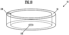
- FIG. 10 is a schematic view showing a structure of a sound pickup device 1A in accordance with a second preferred embodiment. Also in FIG. 10 , a main structure in accordance with sound pickup is shown, and the other structure is not shown.
- the sound pickup device 1A includes two microphones, i.e., a microphone 10A and a microphone 10B.
- the microphone 10A is disposed in a cylinder of the housing 50.
- the microphone 10A has the same structure as that of the microphone 10 shown in FIG. 1 .
- the microphone 10B is disposed on an upper surface of the housing 50.
- the microphone 10B is allowed to acquire not only a voice emitted from a speaker 5 located in a position close to the sound pickup device 1, but also a voice emitted from a speaker 7 located in a position remote from the sound pickup device 1, without being blocked by the housing 50.
- the microphone 10B is disposed on the upper surface of the housing 50.
- the microphone 10B may be disposed on an outer circumference surface of housing 50, or may be disposed in a position away from the housing 50.
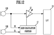
- FIG. 12 is a block diagram of the sound pickup device 1A.
- the sound pickup device 1A includes the microphone 10A, the microphone 10B, a gain adjustment portion 15, a gain calculation portion 17, and an interface (I/F) 19.
- a sound pickup signal S1 of the microphone 10A is inputted to the gain calculation portion 17.
- a sound pickup signal S2 of the microphone 10B is inputted to the gain adjustment portion 15 and the gain calculation portion 17.
- the sound pickup signal S2 of the microphone 10B is subjected to gain adjustment in the gain adjustment portion 15, and inputted to the I/F 19.
- this example shows an aspect in which a gain of the sound pickup signal S2 of the microphone 10B is adjusted and outputted to the I/F 19, but an aspect in which a gain of the sound pickup signal S1 of the microphone 10A is adjusted and outputted to the I/F 19 may be employed. Since the microphone 10A, however, is disposed inside the housing 50 with a cylindrical shape, reflected sounds inside the housing 50 are likely to be picked up, thereby causing a dip or a peak in a predetermined frequency. Therefore, it is preferred that the gain of the sound pickup signal S2 of the microphone 10B is adjusted and outputted to the I/F 19.
- a configuration of the gain calculation portion 17 is the same as that of the gain calculation portion in the first preferred embodiment shown in FIG. 5 .
- pass bands of the filter portion 171A and the filter portion 171B are set in a band in which the values R are most different between a speaker located in a position close to the sound pickup device 1 and a speaker located in a position remote from the sound pickup device 1.
- both the filter portion 171A and the filter portion 171B are low-band limitation processing (high-pass filter) that passes a signal with a band of 1 kHz or more.
- the same processing is performed as in the first preferred embodiment.
- the band limitation processing through the filter portion 171A and the filter portion 171B is not essential. Even if the band limitation processing through the filter portion 171A and the filter portion 171B is not performed, with respect to a remote sound source, the microphone 10A is blocked by the housing 50 and the microphone 10B is not blocked by the housing 50. Accordingly, between the sound picked up by the microphone 10A and the sound picked up by the microphone 10B, the level is different physically. Therefore, even if the band limitation processing through the filter portion 171A and the filter portion 171B is not performed, in a remote place beyond a predetermined distance, the divided value R is reduced as the distance from the sound source is increased.
- the sound pickup device 1A of the second preferred embodiment also has an aspect in which a sound of a sound source whose distance from the microphone 10 is within a predetermined range is picked up, and a sound out of the predetermined range is not picked up.
- a sound source e.g., noise
- the gain can be controlled according to the distance without depending on a size of room, such as a reflected sound.
- FIG. 13 is a schematic view showing a structure of a sound pickup device 1B in accordance with a first modification.
- the sound pickup device 1B has a sound-absorbing material 75 disposed inside a cylinder of the housing 50.
- the other structure is the same as that of the sound pickup device 1.
- sound pickup device 1B can control reflected sounds inside the cylinder. This makes it possible to prevent occurrence of unnecessary dips or peaks in a frequency characteristic of the sound pickup signal of the microphone 10.
- the sound-absorbing material 75 may also be disposed inside the cylinder of the housing 50.
- FIG. 14(A) is a schematic view showing a structure of a sound pickup device 1C in accordance with a second modification.
- FIGS. 14(B) and 14(C) are examples of a transverse sectional view of an indoor room in which the sound pickup device 1C is installed.
- the sound pickup device 1C in the second modification includes an acoustic obstacle 50A with a rectangular parallelepiped shape, and a microphone 10.
- the other structure is the same as that of the block diagram shown in FIGS. 4 and 5 .
- the acoustic obstacles 50 of the sound pickup device 1A and the sound pickup device 1B have a cylindrical shape (the shape is circular when viewed in plan view), but the acoustic obstacle may have a rectangular shape when viewed in plan view.
- various kinds of shapes such as a semi-circle, an elliptical shape, and a polygon when viewed in plan view, may be considered.
- the acoustic obstacle 50A is disposed near the microphone 10.
- the microphone 10 is hidden by the housing 50 in a horizontal direction of a plane on which the sound pickup device 1 is installed.
- the microphone 10 is acoustically opened from the housing 50 at a predetermined angle or more with respect to the horizontal direction of the plane on which the sound pickup device 1 is installed.
- the acoustic obstacle 50A has an example (rectangular parallelepiped shape) of a rectangular shape when viewed in plan view.
- sound pickup to the microphone 10 is blocked in only a specified direction, rather than all circumferential directions.
- the sound pickup device 1C is installed in a front lower part of a display (indicator) 55, and does not pick up a sound in a range having a predetermined angle ⁇ or less among front directions of the display 55.
- the sound pickup device 1C including the acoustic obstacle 50A is also similar. As shown in FIG. 14(C) , in the case of being installed in a ceiling, a sound in a range having a predetermined angle ⁇ or less with respect to the ceiling surface is not picked up.
- the acoustic obstacle can be considered to take various kinds of shapes and arrangements appropriately according to a range in which sound pickup is blocked.
Landscapes
- Health & Medical Sciences (AREA)
- Otolaryngology (AREA)
- Engineering & Computer Science (AREA)
- Physics & Mathematics (AREA)
- Acoustics & Sound (AREA)
- Signal Processing (AREA)
- Multimedia (AREA)
- General Health & Medical Sciences (AREA)
- Circuit For Audible Band Transducer (AREA)
- Obtaining Desirable Characteristics In Audible-Bandwidth Transducers (AREA)
Abstract
Description
- One preferred embodiment of the present invention relates to a sound pickup device that acquires sounds of a sound source by using a microphone, and a sound pickup method.
- To acquire sounds of a sound source appropriately by using a microphone, it is considered to measure a distance between the sound source and the microphone, for example. As a method of measuring a distance between the sound source and the microphone, the sound-source position determining device described in
Patent literature 1 or the technique of Non-PatentLiterature 1 is known, for example. - The sound-source position determining device of
Patent Literature 1 calculates an arrival time difference between a direct sound and a reflected sound. For instance, the shorter a distance between a microphone and a sound source is, the faster the direct sound reaches the microphone. This increases the arrival time difference between the direct sound and the reflected sound. Conversely, the arrival time difference between a direct sound and an indirect sound is reduced as the distance between the microphone and the sound source becomes long. - In the technique of Non-Patent
Literature 1, a position of the sound source is estimated by using the fact that an arrival time difference occurs between a right ear and a left ear. - Patent Literature 1: Unexamined Japanese Patent Publication No.
2013-170936 - Non-Patent literature 1: R. F. Lyon. A computational model of binaural localization and separation. In Proceedings of the International Conference on Acoustics, Speech and Signal Processing, pages 1148-1151, 1983
- For the reflected sound, however, the arrival time is varied depending on environment, such as a size of a room. Accordingly, in the method of using the reflected sound, like
Patent Literature 1, the environment is likely to cause an error in a value of the distance to be estimated. Further, in the technique of Non-Patentliterature 1, sounds coming from the same direction have the same arrival time difference. This makes it difficult to estimate the distance. - One preferred embodiment of the present invention aims to provide a sound pickup device that acquires sounds of a sound source appropriately without depending on environment such as a reflected sound, and a sound pickup method.
- A sound pickup device includes a microphone, an acoustic obstacle, a signal processing portion, and a gain control portion. The acoustic obstacle blocks sound pickup in a predetermined range with respect to the microphone. The signal processing portion splits a sound pickup signal of the microphone into a plurality of sound pickup signals, and subjects at least one sound pickup signal among the plurality of sound pickup signals to band limitation processing. The gain control portion compares characteristic amounts of the plurality of sound pickup signals including the sound pickup signal after being subjected to the band limitation processing by the signal processing portion, and controls a gain of the microphone in accordance with a result of comparing the characteristic amounts.
- Alternatively, the sound pickup device includes a first microphone, a second microphone, an acoustic obstacle, and a gain control portion. The acoustic obstacle blocks sound pickup in a predetermined range with respect to the first microphone. The gain control portion compares characteristic amounts of a sound pickup signal of the first microphone and a sound pickup signal of the second microphone, and controls a gain of the first microphone or the second microphone in accordance with a result of comparing the characteristic amounts.
- According to one preferred embodiment of the present invention, sounds of a sound source can be acquired appropriately, without depending on environment such as a reflected sound.
-
-
FIG. 1 is a schematic view showing a structure of a sound pickup device. -
FIG. 2(A) is a view showing a state where a voice from a speaker close to the sound pickup device reaches, andFIG. 2(B) is a view showing a state where a voice from a speaker remote from the sound pickup device reaches. -
FIG. 3 is a view showing a positional relationship between a microphone, an acoustic obstacle, and a speaker. -
FIG. 4 is a block diagram of the sound pickup device. -
FIG. 5 is a block diagram of again calculation portion 17. -
FIG. 6 is a view showing a relationship between a distance and a level of each sound pickup signal. -
FIG. 7 is a block diagram of thegain calculation portion 17 in the case where an inverse of variance of voice rising time is used as a voice characteristic amount. -
FIG. 8 is a view showing a relationship between a distance and an inverse of variance of voice rising time in the case where the inverse of variance of voice rising time is used as the voice characteristic amount. -
FIG. 9(A) and FIG. 9(B) are views showing a gain table. -
FIG. 10 is a schematic view showing a structure of a sound pickup device including a plurality of microphones. -
FIG. 11(A) is a view showing a state where a voice from a speaker close to the sound pickup device reaches, andFIG. 11(B) is a view showing a state where a voice from a speaker remote from the sound pickup device reaches. -
FIG. 12 is a block diagram of a sound pickup device. -
FIG. 13 is a view showing a structure of a sound pickup device in accordance with a first modification. -
FIG. 14(A) is a perspective view showing a structure of a sound pickup device in accordance with a second modification, andFIGS. 14(B) and 14(C) are examples of a transverse sectional view of an indoor room. -
FIG. 15 is a flowchart showing an operation of the gain calculation portion. -
FIG. 1 is a schematic view showing a structure of asound pickup device 1 in accordance with a first preferred embodiment. InFIG. 1 , a main structure in accordance with sound pickup is shown, and the other structure is not shown. Thesound pickup device 1 includes ahousing 50 with a cylindrical shape, and amicrophone 10. - The
housing 50 is made of metal or resin, and has sound insulating properties. In other words, thehousing 50 is an example of an acoustic obstacle of the present invention. When viewed in plan view, a center portion of thehousing 50 is opened acoustically. - The
microphone 10 is disposed in a cylinder of thehousi5g 50. Themicrophone 10 is hidden by thehousing 50 in a horizontal direction of an installation surface (e.g., top of a desk) on which thesound pickup device 1 is installed. Themicrophone 10 is acoustically opened from thehousing 50 at a predetermined angle or more with respect to the horizontal direction of the installation surface on which thesound pickup device 1 is installed. - The
housing 50 is installed on adesk 70, as shown inFIGS. 2(A) and 2(B) . As shown inFIG. 2(A) , a voice emitted from aspeaker 5 located in a position close to thesound pickup device 1 reaches themicrophone 10 directly, without being blocked by thehousing 50. As shown inFIG. 2B , however, a voice emitted from aspeaker 7 located in a position remote from thesound pickup device 1 is blocked by thehousing 50. As for the voice emitted from thespeaker 7 located in a position remote from thesound pickup device 1, only a component (mainly a low-band component) traveling around thehousing 50 reaches themicrophone 10. -
FIG. 3 is a view showing a positional relationship between themicrophone 10, thehousing 50 serving as an acoustic obstacle, and a speaker (sound source) S. As shown inFIG. 3 , in thesound pickup device 1, a sound of the sound source S is blocked by thehousing 50 at a predetermined angle θ or less with respect to an upper surface of the desk (horizontal direction L). - A range in which the sound of the sound source S is blocked is determined by a relationship between a position of the
microphone 10, a distance L1 to thehousing 50, and a height V1 of thehousing 50. For instance, if L1/V1=1 is satisfied, θ=45 degrees will be obtained. Typically, when a speaker sits on a chair to hold a meeting or the like, a speaker's face is located at a height of approximately 30 cm (V2=30 cm) from top of the desk. Accordingly, if L1/V1=1=L2/V2 is satisfied, L2=V2 will be obtained. A voice of a speaker within a range, which is centered around a position of themicrophone 10 and has a radius of approximately 30 cm, is not blocked by thehousing 50. On the other hand, a voice of a speaker in a range whose distance from themicrophone 10 exceeds approximately 30 cm is blocked by thehousing 50. - Alternatively, if L1/V1=3.33 is almost satisfied, θ=16 degrees will be obtained. Further, if L1/V1=3.33=L2/V2 is satisfied, L2=3.33·V2 will be obtained. Accordingly, a voice of a speaker within a range having a radius of approximately 100 cm is not blocked by the
housing 50. On the other hand, a voice of a speaker in a range whose distance from themicrophone 10 exceeds approximately 100 cm is blocked by thehousing 50. - Typically, in the case of holding a meeting or the like, a speaker is located within a range whose distance from a closest position to a desk is approximately 100 cm. Accordingly, a ratio (L1/V1) of L1 to V1 is desired to be set to approximately a value ranging from 1 to 3.33. Thus, a voice in a range having a radius of approximately 30 cm to 100 cm reaches the
microphone 10 without being blocked by thehousing 50, and a voice out of the range having a radius of approximately 30 cm to 100 cm is blocked by thehousing 50. -
FIG. 4 is a block diagram of thesound pickup device 1. Thesound pickup device 1 includes themicrophone 10, again adjustment portion 15, again calculation portion 17, and an interface (I/F) 19. - A sound pickup signal, which is the voice acquired by the
microphone 10, is subjected to gain adjustment in thegain adjustment portion 15 and inputted to the I/F 19. The I/F 19 is, for example, a communication I/F and transmits the sound pickup signal to an external device (remote area). Alternatively, the I/F 19 outputs the sound pickup signal to a storage portion (not shown). The storage portion records the sound pickup signal, which is acquired by themicrophone 10, as recording data. - The
gain calculation portion 17 sets a gain of thegain adjustment portion 15. A gain control portion in the present invention is constituted by thegain adjustment portion 15 and thegain calculation portion 17. The sound pickup signal is inputted to thegain calculation portion 17. Herein, the sound pickup signal is split into a plurality of sound pickup signals (a sound pickup signal S1 and a sound pickup signal S2). Note that, the function of thegain adjustment portion 15 and thegain calculation portion 17 can be achieved by a common information processor, such as a personal computer. In this case, the information processor reads out a program stored in a storage medium, such as a flash memory, and executes the program, thereby achieving the function of thegain adjustment portion 15 and thegain calculation portion 17. -
FIG. 5 is a block diagram (functional block diagram) showing a configuration of thegain calculation portion 17. Further,FIG. 15 is a flowchart showing an operation of thegain calculation portion 17. Thegain calculation portion 17 includes a filter portion (Filter) 171A, afilter portion 171B, an absolute value calculation portion (Absolute) 172A, an absolutevalue calculation portion 172B, an average processing portion (Average) 173A, anaverage processing portion 173B, a comparing portion (Compare) 174, and a gain calculation portion (Gain) 175. - The sound pickup signal S1 is inputted to the
filter portion 171A, and the sound pickup signal S2 is inputted to thefilter portion 171B. Thefilter portion 171A and thefilter portion 171B each perform band limitation processing (S11). - The
filter portion 171A and thefilter portion 171B perform processing of extracting a band in which a difference in acoustic characteristic amount occurs between the voice emitted from a speaker located in a position close to thesound pickup device 1 and the voice emitted from a speaker located in a position remote from thesound pickup device 1. - For instance, the
filter portion 171A is low-band limitation processing (high-pass filter), and thefilter portion 171B is all-band pass processing (all-pass filter). As mentioned above, the voice emitted from the speaker located in a position close to thesound pickup device 1 reaches themicrophone 10, without being blocked by thehousing 50. As for the voice emitted from a speaker located in a position remote from thesound pickup device 1, a component (mainly low-band component) traveling around thehousing 50 reaches themicrophone 10. Accordingly, in the voice emitted from the speaker located in a position close to thesound pickup device 1, a significant level difference does not occur between an output signal of thefilter portion 171B and an output signal of thefilter portion 171A. On the other hand, in the voice emitted from the speaker located in a position remote from thesound pickup device 1, a high-band component is blocked by thehousing 50, thereby making it difficult to reach themicrophone 10. Therefore, the level of the output signal of thefilter portion 171A is remarkably reduced, thereby increasing the level difference between the output signal of thefilter portion 171B and the output signal of thefilter portion 171A. - An output signal (sound pickup signal) S1-1 of the
filter portion 171A is subjected to absolute value processing in the absolutevalue calculation portion 172A and calculated as a power value S1-2 (S12). The calculated power value is averaged over a predetermined time range in theaverage processing portion 173A to obtain an average power value S1-3 (S13). An output signal (sound pickup signal) S2-1 of thefilter portion 171B is subjected to absolute value processing in the absolutevalue calculation portion 172B and calculated as a power value S2-2 (S12). The calculated power value is averaged over a predetermined time range in theaverage processing portion 173B to obtain an average power value S2-3 (S13) . - The comparing
portion 174 calculates a value R (S14). The value R is obtained by dividing an output value (average power value) S1-3 of theaverage processing portion 173A by an output value (average power value) S2-3 of theaverage processing portion 173B. The division is an example of a method for comparing the acoustic characteristic amount. Other than this, the output signal of theaverage processing portion 173A is subtracted from the output signal of theaverage processing portion 173B, and the resulting differential value may be defined as the value R, for example.FIG. 6 is a view showing a relationship between a distance and a level of each sound pickup signal. A level (e.g., power value) of the sound pickup signal S2-1 decreases as a distance from themicrophone 10 becomes long. As shown inFIG. 3 , at a position farther than the distance L2, the arrival of voice is blocked by thehousing 50. Thus, the degree of reduction in a level of the sound pickup signal S2-1 is increased as the distance from themicrophone 10 becomes long. - On the other hand, up to the distance L2, the sound pickup signal S1-1 is decreased as the distance from
microphone 10 becomes long, like the sound pickup signal S2-1. At a position farther than the distance L2, the arrival of voice is blocked by thehousing 50, and the low-band component, which is easy to travel around themicrophone 10, is cut off. Therefore, the degree of reduction in a level of the sound pickup signal S1-1 is further increased as the distance from themicrophone 10 becomes long. Consequently, the value R is reduced significantly, when the sound source is located at a position farther than the distance L2. - Further, the
sound pickup device 1 may calculate the value R using the inverse of variance of voice rising time in a different frequency band, as a characteristic amount.FIG. 7 is a block diagram (functional block diagram) showing a configuration of thegain calculation portion 17 when the inverse of variance of voice rising time in a different frequency band is used as the characteristic amount. - The
gain calculation portion 17 includes afilter portion 171A, afilter portion 171B, aband division portion 182A, aband division portion 182B, a risetime detection portion 183A, a risetime detection portion 183B, avariance calculation portion 184A, avariance calculation portion 184B, an inversenumber calculation portion 185A, an inversenumber calculation portion 185B, a comparingportion 174, and again calculation portion 175. - In this case, an output signal S1-1 of the
filter portion 171A is inputted to theband division portion 182A, and then divided into still fine bands to obtain a signal S1-4. The signal S1-4 is inputted to the risetime detection portion 182A. An output signal S2-1 of thefilter portion 171B is inputted toband division portion 182B, and then divided into still fine bands to obtain a signal S2-4. The signal S2-4 is inputted to the risetime detection portion 182B. The risetime detection portion 182A calculates the time when a level of the signal S1-4 exceeds a given threshold, and outputs it as a time value S1-5. The time value S1-5 is inputted to thevariance calculation portion 184A. The risetime detection portion 182B calculates the time when a level of the signal S2-4 exceeds a given threshold, and outputs it as a time value S2-5. The time value S2-5 is inputted to thevariance calculation portion 184B. Thevariance calculation portion 184A calculates a variance value of the time value S1-5 related to the band, and outputs it as a variance value S1-6. The variance value S1-6 is converted into an inverse number S1-7 through the inversenumber calculation portion 185A. Thevariance calculation portion 184B calculates a variance value of the time value S2-5 related to the band, and outputs it as a variance value S2-6. The variance value S2-6 is converted into an inverse number S2-7 through the inversenumber calculation portion 185B. The comparingportion 174 divides the inverse number S1-7 by the inverse number S2-7 to output a value R. -
FIG. 8 is a view showing a relationship between a distance, and the inverse number S1-7 and the inverse number S2-7. Since an all-pass filter is applied in thefilter portion 171A, the output signal S1-1 includes a low-band component, which is hard to be affected by an obstacle. Accordingly, in the signal S1-1, a direct sound is dominant rather than an indirect sound due to reflection in a room or the like, even if a position of the sound source is closer or farther than the distance L2. The time value S1-5, which indicates the time when a sound wave reaches, is almost the same for every frequency, because the direct sound travels on the shortest path from the sound source to themicrophone 10. Therefore, the variance value S1-6, which indicates variance of rise time, is reduced, so that the inverse number S1-7, which indicates an inverse of vairance of rise time, has a large value. - On the other hand, since a high-pass filter is applied in the
filter portion 172A, only a component easily affected by an obstacle exists in the output signal S2-1. As shown inFIG. 3 , at a position farther than the distance L2, the arrival of direct sound is blocked by thehousing 50. Accordingly, a proportion of the indirect sound in the output signal S2-1 is increased as the distance from themicrophone 10 becomes long. Since the indirect sound reaches themicrophone 10 after being reflected on the inside of a room repeatedly, the arrival time differs significantly depending on frequency. Thus, the variance S2-6 of rise time is further increased, and the inverse number S2-7 is reduced seriously. Therefore, if it exceeds the distance L2, the inverse number S1-7 and the inverse number S2-7 will differ from each other significantly. Consequently, when a position of the sound source is farther than the distance L2, the value R is reduced significantly. - The
gain calculation portion 175 calculates a gain G according to the value R (S15).FIG. 9(A) is a view showing an example of a gain table. As shown inFIG. 9(A) , in the gain table, when the value R is more than or equal to a predetermined value R1, no attenuation occurs. From the predetermined value R1 to R2, the gain G is set to be attenuated as the value R is reduced. When the value R is smaller than R2, the minimum gain value is maintained. - When a position of the sound source is farther than the distance L2, the value R is decreased according to an increase in the distance. The predetermined value R1 and the predetermined value R2 may be set optionally, but the predetermined value R1 is set according to the maximum range in which sound pickup is desired to be performed without being attenuated. For instance, a ratio (L1/V1) of L1 to V1 is assumed to be 1. When a position of the sound source is farther than a radius of approximately 30 cm, the value R is reduced. However, if the predetermined value R1 is set to a value R obtained when the distance is approximately 40 cm, a sound can be picked up without being attenuated, up to a radius of approximately 40 cm. Further, the predetermined value R2 is set according to the minimum range in which the attenuation is desired. For instance, if the predetermined value R2 is set to a value R obtained when the distance is 100 cm, sound pickup will scarcely be performed when the distance is more than or equal to 100 cm. When the distance is closer than 100 cm, the gain gradually increases, so that sound pickup is performed.
- Further, the predetermined values R1 and R2 are not a fixed value, but may be changed dynamically. For instance, among the values R that have been calculated in the past time within predetermined time, the maximum value is determined as a value R0 to obtain the predetermined value R1=R0+0.1 and the predetermined value R2=R0-0.1. Thus, with the current position of the sound source as a reference, a sound in a range closer to the
microphone 10 than the position of the sound source is picked up, and a sound farther than the position of the sound source is not picked up. - The example of
FIG. 9(A) is an aspect in which the gain decreases rapidly from a predetermined distance (e.g., 30 cm) and the sound source whose position is farther than a predetermined distance (e.g., 100 cm) is scarcely picked up, which is similar to the function of a limiter. Other than this, however, various kinds of aspects can be considered as the gain table, as shown inFIG. 9(B) . The example ofFIG. 9(B) is an aspect in which the gain gradually decreases according to the distance, the degree of decrease in the gain is increased from a predetermined distance (e.g., 30 cm), and the gain gradually decreases again at more than or equal to a predetermined distance (e.g., 100 cm), which is similar to the function of a compressor. - As mentioned above, the
sound pickup device 1 in the present preferred embodiment has an aspect that picks up a sound of the sound source whose distance from themicrophone 10 is within a predetermined range, and does not pick up a sound out of the predetermined range. This makes it possible to reduce a sound source (e.g., noise) in a remote place, remarkably. In technique of the present preferred embodiment, also for a sound coming from the same direction, the gain can be controlled according to the distance without depending on a size of room, such as a reflected sound. - Next,
FIG. 10 is a schematic view showing a structure of asound pickup device 1A in accordance with a second preferred embodiment. Also inFIG. 10 , a main structure in accordance with sound pickup is shown, and the other structure is not shown. Thesound pickup device 1A includes two microphones, i.e., amicrophone 10A and amicrophone 10B. - In the
sound pickup device 1A of this example, themicrophone 10A is disposed in a cylinder of thehousing 50. In other words, themicrophone 10A has the same structure as that of themicrophone 10 shown inFIG. 1 . In thesound pickup device 1A, themicrophone 10B is disposed on an upper surface of thehousing 50. - As shown in
FIGS. 11(A) and 11(B) , themicrophone 10B is allowed to acquire not only a voice emitted from aspeaker 5 located in a position close to thesound pickup device 1, but also a voice emitted from aspeaker 7 located in a position remote from thesound pickup device 1, without being blocked by thehousing 50. - Note that, it is not essential that the
microphone 10B is disposed on the upper surface of thehousing 50. For instance, themicrophone 10B may be disposed on an outer circumference surface ofhousing 50, or may be disposed in a position away from thehousing 50. -
FIG. 12 is a block diagram of thesound pickup device 1A. Thesound pickup device 1A includes themicrophone 10A, themicrophone 10B, again adjustment portion 15, again calculation portion 17, and an interface (I/F) 19. - A sound pickup signal S1 of the
microphone 10A is inputted to thegain calculation portion 17. A sound pickup signal S2 of themicrophone 10B is inputted to thegain adjustment portion 15 and thegain calculation portion 17. The sound pickup signal S2 of themicrophone 10B is subjected to gain adjustment in thegain adjustment portion 15, and inputted to the I/F 19. - Note that, this example shows an aspect in which a gain of the sound pickup signal S2 of the
microphone 10B is adjusted and outputted to the I/F 19, but an aspect in which a gain of the sound pickup signal S1 of themicrophone 10A is adjusted and outputted to the I/F 19 may be employed. Since themicrophone 10A, however, is disposed inside thehousing 50 with a cylindrical shape, reflected sounds inside thehousing 50 are likely to be picked up, thereby causing a dip or a peak in a predetermined frequency. Therefore, it is preferred that the gain of the sound pickup signal S2 of themicrophone 10B is adjusted and outputted to the I/F 19. - A configuration of the
gain calculation portion 17 is the same as that of the gain calculation portion in the first preferred embodiment shown inFIG. 5 . However, pass bands of thefilter portion 171A and thefilter portion 171B are set in a band in which the values R are most different between a speaker located in a position close to thesound pickup device 1 and a speaker located in a position remote from thesound pickup device 1. For instance, both thefilter portion 171A and thefilter portion 171B are low-band limitation processing (high-pass filter) that passes a signal with a band of 1 kHz or more. For the other configurations, the same processing is performed as in the first preferred embodiment. - Note that, in the second preferred embodiment, the band limitation processing through the
filter portion 171A and thefilter portion 171B is not essential. Even if the band limitation processing through thefilter portion 171A and thefilter portion 171B is not performed, with respect to a remote sound source, themicrophone 10A is blocked by thehousing 50 and themicrophone 10B is not blocked by thehousing 50. Accordingly, between the sound picked up by themicrophone 10A and the sound picked up by themicrophone 10B, the level is different physically. Therefore, even if the band limitation processing through thefilter portion 171A and thefilter portion 171B is not performed, in a remote place beyond a predetermined distance, the divided value R is reduced as the distance from the sound source is increased. - Accordingly, like the first preferred embodiment, the
sound pickup device 1A of the second preferred embodiment also has an aspect in which a sound of a sound source whose distance from themicrophone 10 is within a predetermined range is picked up, and a sound out of the predetermined range is not picked up. This makes it possible to reduce a sound source (e.g., noise) in a remote place, remarkably. Even in the second preferred embodiment, also for a sound coming from the same direction, the gain can be controlled according to the distance without depending on a size of room, such as a reflected sound. -
FIG. 13 is a schematic view showing a structure of a sound pickup device 1B in accordance with a first modification. The sound pickup device 1B has a sound-absorbingmaterial 75 disposed inside a cylinder of thehousing 50. The other structure is the same as that of thesound pickup device 1. - Since the sound-absorbing
material 75 is disposed inside the cylinder of thehousing 50, sound pickup device 1B can control reflected sounds inside the cylinder. This makes it possible to prevent occurrence of unnecessary dips or peaks in a frequency characteristic of the sound pickup signal of themicrophone 10. - Note that, in the second preferred embodiment, the sound-absorbing
material 75 may also be disposed inside the cylinder of thehousing 50. - Next,
FIG. 14(A) is a schematic view showing a structure of asound pickup device 1C in accordance with a second modification.FIGS. 14(B) and 14(C) are examples of a transverse sectional view of an indoor room in which thesound pickup device 1C is installed. - The
sound pickup device 1C in the second modification includes anacoustic obstacle 50A with a rectangular parallelepiped shape, and amicrophone 10. The other structure is the same as that of the block diagram shown inFIGS. 4 and5 . Theacoustic obstacles 50 of thesound pickup device 1A and the sound pickup device 1B have a cylindrical shape (the shape is circular when viewed in plan view), but the acoustic obstacle may have a rectangular shape when viewed in plan view. Other than this, various kinds of shapes, such as a semi-circle, an elliptical shape, and a polygon when viewed in plan view, may be considered. - The
acoustic obstacle 50A is disposed near themicrophone 10. Themicrophone 10 is hidden by thehousing 50 in a horizontal direction of a plane on which thesound pickup device 1 is installed. Themicrophone 10 is acoustically opened from thehousing 50 at a predetermined angle or more with respect to the horizontal direction of the plane on which thesound pickup device 1 is installed. - The
acoustic obstacle 50A, however, has an example (rectangular parallelepiped shape) of a rectangular shape when viewed in plan view. Thus, sound pickup to themicrophone 10 is blocked in only a specified direction, rather than all circumferential directions. For instance, in the example ofFIG. 14(B) , thesound pickup device 1C is installed in a front lower part of a display (indicator) 55, and does not pick up a sound in a range having a predetermined angle θ or less among front directions of thedisplay 55. - In the case where being installed in a ceiling, the
sound pickup device 1C including theacoustic obstacle 50A is also similar. As shown inFIG. 14(C) , in the case of being installed in a ceiling, a sound in a range having a predetermined angle θ or less with respect to the ceiling surface is not picked up. - In this way, the acoustic obstacle can be considered to take various kinds of shapes and arrangements appropriately according to a range in which sound pickup is blocked.
- The description of the present preferred embodiment is illustrative in all respects, and should not be construed to be restrictive. The scope of the present invention is indicated by the appended claims rather than by the above-mentioned preferred embodiments. Furthermore, the scope of the present invention includes the scope of claims and equivalent scope of claims.
-
- 1, 1A, 1B, 1C
- sound pickup device
- 10, 10A, 10B
- microphone
- 15
- gain adjustment portion
- 17
- gain calculation portion
- 19
- I/F
- 50
- housing
- 50A
- acoustic obstacle
- 55
- display
- 70
- desk top surface
- 75
- sound-absorbing material
- 171A, 171B
- filter portion
- 172A, 172B
- absolute value calculation portion
- 173A, 173B
- average processing portion
- 174
- comparing portion
- 175
- gain calculation portion
- 182A, 182B
- band division portion
- 183A, 183B
- rise time detection portion
- 184A, 184B
- variance calculation portion
- 185A, 185B
- inverse number calculation portion
Claims (16)
- A sound pickup device comprising:a microphone;an acoustic obstacle that blocks sound pickup in a predetermined range with respect to the microphone;a signal processing portion that splits a sound pickup signal of the microphone into a plurality of sound pickup signals and subjects at least one sound pickup signal among the plurality of sound pickup signals to band limitation processing; anda gain control portion that compares characteristic amounts of the plurality of sound pickup signals including the sound pickup signal after being subjected to the band limitation processing by the signal processing portion, and controls a gain of the microphone in accordance with a result of comparing the characteristic amounts.
- The sound pickup device according to claim 1, wherein the band limitation processing includes low-band limitation processing.
- A sound pickup device comprising:a first microphone;a second microphone;an acoustic obstacle that blocks sound pickup in a predetermined range with respect to the first microphone; anda gain control portion that compares characteristic amounts of a sound pickup signal of the first microphone and a sound pickup signal of the second microphone, and controls a gain of the first microphone or the second microphone in accordance with a result of comparing the characteristic amounts.
- The sound pickup device according to claim 3, wherein the gain control portion controls the gain of the second microphone.
- The sound pickup device according to claims 1 to 4, wherein, when the sound pickup signal includes a sound of a sound source belonging to the predetermined range, the characteristic amounts are changed by the acoustic obstacle.
- The sound pickup device according to any one of claims 1 to 5, wherein the characteristic amounts include a signal level.
- The sound pickup device according to any one of claims 1 to 5, wherein the characteristic amounts include variance of rise time in different frequency.
- The sound pickup device according to any one of claims 1 to 7, wherein the gain control portion reduces an output level with respect to an input level, when a difference or a ratio between the characteristic amounts of the plurality of sound pickup signals is increased to more than or equal to a predetermined value.
- The sound pickup device according to any one of claims 1 to 8, wherein the gain control portion changes an output level with respect to an input level in accordance with a change in a difference or a ratio between the characteristic amounts of the plurality of sound pickup signals.
- The sound pickup device according to any one of claims 1 to 9, wherein the acoustic obstacle is constituted by a housing with a cylindrical shape.
- The sound pickup device according to any one of claims 1 to 9, wherein the acoustic obstacle is constituted by a housing with a rectangular parallelepiped shape.
- The sound pickup device according to any one of claims 1 to 11, wherein the predetermined range is a range having a predetermined angle or less with respect to a horizontal direction of an installation surface on which the sound pickup device is installed.
- The sound pickup device according to claim 12, wherein the predetermined range is a range having an angle of 16 degrees or less with respect to the horizontal direction of the installation surface on which the sound pickup device is installed.
- The sound pickup device according to any one of claims 1 to 13, further comprising a sound-absorbing material disposed near the acoustic obstacle.
- A sound pickup method comprising:splitting a sound pickup signal of a microphone of which sound pickup in a predetermined range is blocked by an acoustic obstacle, into a plurality of sound pickup signals and subjecting at least one sound pickup signal among the plurality of sound pickup signals to band limitation processing; andcomparing characteristic amounts of the plurality of sound pickup signals including the sound pickup signal after being subjected to the band limitation processing and controlling a gain of the microphone in accordance with a result of comparing the characteristic amounts.
- A sound pickup method comprising:comparing characteristic amounts of a sound pickup signal of a first microphone of which sound pickup in a predetermined range is blocked by an acoustic obstacle, and a sound pickup signal of a second microphone; andcontrolling a gain of the first microphone or the second microphone in accordance with a result of comparing the characteristic amounts.
Applications Claiming Priority (1)
| Application Number | Priority Date | Filing Date | Title |
|---|---|---|---|
| PCT/JP2017/012070 WO2018173266A1 (en) | 2017-03-24 | 2017-03-24 | Sound pickup device and sound pickup method |
Publications (2)
| Publication Number | Publication Date |
|---|---|
| EP3606091A1 true EP3606091A1 (en) | 2020-02-05 |
| EP3606091A4 EP3606091A4 (en) | 2020-11-18 |
Family
ID=63585199
Family Applications (1)
| Application Number | Title | Priority Date | Filing Date |
|---|---|---|---|
| EP17901745.4A Withdrawn EP3606091A4 (en) | 2017-03-24 | 2017-03-24 | SOUND RECORDING DEVICE AND SOUND RECORDING METHOD |
Country Status (5)
| Country | Link |
|---|---|
| US (2) | US11197091B2 (en) |
| EP (1) | EP3606091A4 (en) |
| JP (1) | JP6828804B2 (en) |
| CN (1) | CN110447237B (en) |
| WO (1) | WO2018173266A1 (en) |
Families Citing this family (1)
| Publication number | Priority date | Publication date | Assignee | Title |
|---|---|---|---|---|
| CN113973257B (en) * | 2020-07-23 | 2025-02-14 | 阿里巴巴集团控股有限公司 | A sound pickup device |
Family Cites Families (28)
| Publication number | Priority date | Publication date | Assignee | Title |
|---|---|---|---|---|
| JPH071958B2 (en) * | 1986-06-20 | 1995-01-11 | 松下電器産業株式会社 | Sound pickup device |
| US4862278A (en) * | 1986-10-14 | 1989-08-29 | Eastman Kodak Company | Video camera microphone with zoom variable acoustic focus |
| US5550925A (en) * | 1991-01-07 | 1996-08-27 | Canon Kabushiki Kaisha | Sound processing device |
| GB9211756D0 (en) * | 1992-06-03 | 1992-07-15 | Gerzon Michael A | Stereophonic directional dispersion method |
| JP4247037B2 (en) * | 2003-01-29 | 2009-04-02 | 株式会社東芝 | Audio signal processing method, apparatus and program |
| JP4218573B2 (en) * | 2004-04-12 | 2009-02-04 | ソニー株式会社 | Noise reduction method and apparatus |
| JP4612468B2 (en) * | 2005-05-19 | 2011-01-12 | 日本電信電話株式会社 | Signal extraction device |
| EP1965603B1 (en) * | 2005-12-19 | 2017-01-11 | Yamaha Corporation | Sound emission and collection device |
| EP1862813A1 (en) * | 2006-05-31 | 2007-12-05 | Honda Research Institute Europe GmbH | A method for estimating the position of a sound source for online calibration of auditory cue to location transformations |
| JP2009272893A (en) * | 2008-05-08 | 2009-11-19 | Yamaha Corp | Sound pickup apparatus |
| KR101392546B1 (en) * | 2008-09-11 | 2014-05-08 | 프라운호퍼 게젤샤프트 쭈르 푀르데룽 데어 안겐반텐 포르슝 에. 베. | Apparatus, method and computer program for providing a set of spatial cues on the basis of a microphone signal and apparatus for providing a two-channel audio signal and a set of spatial cues |
| JP5168079B2 (en) * | 2008-10-22 | 2013-03-21 | ヤマハ株式会社 | Sound equipment |
| EP2492912B1 (en) * | 2009-10-21 | 2018-12-05 | Panasonic Intellectual Property Corporation of America | Sound processing apparatus, sound processing method and hearing aid |
| JP2011147103A (en) * | 2009-12-15 | 2011-07-28 | Canon Inc | Audio signal processing device |
| CN102137318B (en) * | 2010-01-22 | 2014-08-20 | 华为终端有限公司 | Method and device for controlling adapterization |
| DK2375781T3 (en) * | 2010-04-07 | 2013-06-03 | Oticon As | Method of controlling a binaural hearing aid system and binaural hearing aid system |
| US8620650B2 (en) | 2011-04-01 | 2013-12-31 | Bose Corporation | Rejecting noise with paired microphones |
| US9194938B2 (en) * | 2011-06-24 | 2015-11-24 | Amazon Technologies, Inc. | Time difference of arrival determination with direct sound |
| JP5817366B2 (en) * | 2011-09-12 | 2015-11-18 | 沖電気工業株式会社 | Audio signal processing apparatus, method and program |
| CN104041075B (en) * | 2012-01-17 | 2017-10-24 | 皇家飞利浦有限公司 | Audio Source Position Estimation |
| JP5815435B2 (en) | 2012-02-21 | 2015-11-17 | 日本電信電話株式会社 | Sound source position determination apparatus, sound source position determination method, program |
| US20140056429A1 (en) * | 2012-08-27 | 2014-02-27 | Quickfilter Technologies, Llc | Spatialization using stereo decorrelation |
| US20140112483A1 (en) * | 2012-10-24 | 2014-04-24 | Alcatel-Lucent Usa Inc. | Distance-based automatic gain control and proximity-effect compensation |
| WO2014101156A1 (en) * | 2012-12-31 | 2014-07-03 | Spreadtrum Communications (Shanghai) Co., Ltd. | Adaptive audio capturing |
| JP6031364B2 (en) | 2013-01-24 | 2016-11-24 | 日本電信電話株式会社 | Sound collection device and playback device |
| WO2014125860A1 (en) * | 2013-02-12 | 2014-08-21 | 日本電気株式会社 | Speech processing device, speech processing method, speech processing program, attachment method for speech processing device, ceiling member, and vehicle |
| US9467779B2 (en) * | 2014-05-13 | 2016-10-11 | Apple Inc. | Microphone partial occlusion detector |
| FR3036912A1 (en) * | 2015-05-28 | 2016-12-02 | Corsin Vogel | COMPACT DEVICE FOR RECEIVING MULTI-CHANNEL SOUND BY ACOUSTIC DIFFRACTION ON A PHYSICAL OBSTACLE |
-
2017
- 2017-03-24 CN CN201780088836.3A patent/CN110447237B/en not_active Expired - Fee Related
- 2017-03-24 WO PCT/JP2017/012070 patent/WO2018173266A1/en not_active Ceased
- 2017-03-24 JP JP2019506897A patent/JP6828804B2/en not_active Expired - Fee Related
- 2017-03-24 EP EP17901745.4A patent/EP3606091A4/en not_active Withdrawn
-
2019
- 2019-09-20 US US16/576,994 patent/US11197091B2/en not_active Expired - Fee Related
-
2021
- 2021-11-01 US US17/515,916 patent/US11758322B2/en active Active
Also Published As
| Publication number | Publication date |
|---|---|
| US11197091B2 (en) | 2021-12-07 |
| US11758322B2 (en) | 2023-09-12 |
| CN110447237A (en) | 2019-11-12 |
| WO2018173266A1 (en) | 2018-09-27 |
| US20220060816A1 (en) | 2022-02-24 |
| EP3606091A4 (en) | 2020-11-18 |
| US20200015003A1 (en) | 2020-01-09 |
| JP6828804B2 (en) | 2021-02-10 |
| JPWO2018173266A1 (en) | 2020-01-23 |
| CN110447237B (en) | 2022-04-15 |
Similar Documents
| Publication | Publication Date | Title |
|---|---|---|
| KR101275442B1 (en) | Systems, methods, apparatus, and computer-readable media for phase-based processing of multichannel signal | |
| CN102007776B (en) | Hearing aids | |
| CN103026733B (en) | Systems, methods, devices, and computer-readable media for multi-microphone position-selective processing | |
| KR101492758B1 (en) | Methods, apparatus, and computer-readable media for orientation-sensitive recording control | |
| KR102942910B1 (en) | Wind noise detection systems and methods | |
| KR20200009035A (en) | Correlation Based Near Field Detector | |
| CA2824439A1 (en) | Dynamic enhancement of audio (dae) in headset systems | |
| EP3905718B1 (en) | Sound pickup device and sound pickup method | |
| KR20140030686A (en) | System for improving voice recognition of the array microphone for vehicle and method thereof | |
| US11877133B2 (en) | Audio output using multiple different transducers | |
| US11758322B2 (en) | Sound pickup device and sound pickup method | |
| JPWO2009093416A1 (en) | Audio signal processing apparatus and method | |
| US11070907B2 (en) | Signal matching method and device | |
| JP7040568B2 (en) | Sound collecting device and sound collecting method | |
| JP6639747B2 (en) | Noise removal device and noise removal method | |
| EP3764360B1 (en) | Signal processing methods and systems for beam forming with improved signal to noise ratio | |
| Ni et al. | A robust GSC beamforming method for speech enhancement using linear microphone array | |
| US12075217B2 (en) | Signal processing methods and systems for adaptive beam forming | |
| EP3764358B1 (en) | Signal processing methods and systems for beam forming with wind buffeting protection | |
| Tsujikawa et al. | Automatic speech translation system selecting target language by direction-of-arrival information | |
| Hua et al. | A new adaptation mode controller for adaptive microphone arrays based on nested and symmetric leaky blocking matrices | |
| Qi | Real-time adaptive noise cancellation for automatic speech recognition in a car environment: a thesis presented in partial fulfillment of the requirements for the degree of Doctor of Philosophy in Computer Engineering at Massey University, School of Engineering and Advanced Technology, Auckland, New Zealand |
Legal Events
| Date | Code | Title | Description |
|---|---|---|---|
| STAA | Information on the status of an ep patent application or granted ep patent |
Free format text: STATUS: THE INTERNATIONAL PUBLICATION HAS BEEN MADE |
|
| PUAI | Public reference made under article 153(3) epc to a published international application that has entered the european phase |
Free format text: ORIGINAL CODE: 0009012 |
|
| STAA | Information on the status of an ep patent application or granted ep patent |
Free format text: STATUS: REQUEST FOR EXAMINATION WAS MADE |
|
| 17P | Request for examination filed |
Effective date: 20190917 |
|
| AK | Designated contracting states |
Kind code of ref document: A1 Designated state(s): AL AT BE BG CH CY CZ DE DK EE ES FI FR GB GR HR HU IE IS IT LI LT LU LV MC MK MT NL NO PL PT RO RS SE SI SK SM TR |
|
| AX | Request for extension of the european patent |
Extension state: BA ME |
|
| DAV | Request for validation of the european patent (deleted) | ||
| DAX | Request for extension of the european patent (deleted) | ||
| A4 | Supplementary search report drawn up and despatched |
Effective date: 20201020 |
|
| RIC1 | Information provided on ipc code assigned before grant |
Ipc: H04R 1/08 20060101ALI20201014BHEP Ipc: H03G 3/30 20060101ALI20201014BHEP Ipc: H04R 1/34 20060101ALI20201014BHEP Ipc: H04R 3/00 20060101AFI20201014BHEP Ipc: H04R 1/40 20060101ALI20201014BHEP |
|
| STAA | Information on the status of an ep patent application or granted ep patent |
Free format text: STATUS: EXAMINATION IS IN PROGRESS |
|
| 17Q | First examination report despatched |
Effective date: 20220705 |
|
| GRAP | Despatch of communication of intention to grant a patent |
Free format text: ORIGINAL CODE: EPIDOSNIGR1 |
|
| STAA | Information on the status of an ep patent application or granted ep patent |
Free format text: STATUS: GRANT OF PATENT IS INTENDED |
|
| INTG | Intention to grant announced |
Effective date: 20240314 |
|
| STAA | Information on the status of an ep patent application or granted ep patent |
Free format text: STATUS: THE APPLICATION IS DEEMED TO BE WITHDRAWN |
|
| 18D | Application deemed to be withdrawn |
Effective date: 20240716 |