EP3605872A1 - Message relaying in vehicle-to-vehicle communication system - Google Patents
Message relaying in vehicle-to-vehicle communication system Download PDFInfo
- Publication number
- EP3605872A1 EP3605872A1 EP19182701.3A EP19182701A EP3605872A1 EP 3605872 A1 EP3605872 A1 EP 3605872A1 EP 19182701 A EP19182701 A EP 19182701A EP 3605872 A1 EP3605872 A1 EP 3605872A1
- Authority
- EP
- European Patent Office
- Prior art keywords
- message
- vehicle
- rsu
- signal
- pattern
- Prior art date
- Legal status (The legal status is an assumption and is not a legal conclusion. Google has not performed a legal analysis and makes no representation as to the accuracy of the status listed.)
- Withdrawn
Links
- 238000004891 communication Methods 0.000 title claims abstract description 11
- 238000001914 filtration Methods 0.000 claims abstract description 5
- 238000000034 method Methods 0.000 abstract description 17
- 239000013598 vector Substances 0.000 description 13
- 238000010586 diagram Methods 0.000 description 8
- 230000005540 biological transmission Effects 0.000 description 4
- 230000015654 memory Effects 0.000 description 4
- 230000008569 process Effects 0.000 description 4
- 230000006870 function Effects 0.000 description 3
- 238000011084 recovery Methods 0.000 description 3
- 241000497429 Obus Species 0.000 description 1
- 230000008878 coupling Effects 0.000 description 1
- 238000010168 coupling process Methods 0.000 description 1
- 238000005859 coupling reaction Methods 0.000 description 1
- 230000003993 interaction Effects 0.000 description 1
- 230000003287 optical effect Effects 0.000 description 1
- 239000004065 semiconductor Substances 0.000 description 1
- 238000000926 separation method Methods 0.000 description 1
- 230000007704 transition Effects 0.000 description 1
Images

Classifications
-
- H—ELECTRICITY
- H04—ELECTRIC COMMUNICATION TECHNIQUE
- H04B—TRANSMISSION
- H04B7/00—Radio transmission systems, i.e. using radiation field
- H04B7/02—Diversity systems; Multi-antenna system, i.e. transmission or reception using multiple antennas
- H04B7/04—Diversity systems; Multi-antenna system, i.e. transmission or reception using multiple antennas using two or more spaced independent antennas
- H04B7/08—Diversity systems; Multi-antenna system, i.e. transmission or reception using multiple antennas using two or more spaced independent antennas at the receiving station
- H04B7/0837—Diversity systems; Multi-antenna system, i.e. transmission or reception using multiple antennas using two or more spaced independent antennas at the receiving station using pre-detection combining
- H04B7/0842—Weighted combining
- H04B7/086—Weighted combining using weights depending on external parameters, e.g. direction of arrival [DOA], predetermined weights or beamforming
-
- H—ELECTRICITY
- H04—ELECTRIC COMMUNICATION TECHNIQUE
- H04W—WIRELESS COMMUNICATION NETWORKS
- H04W4/00—Services specially adapted for wireless communication networks; Facilities therefor
- H04W4/30—Services specially adapted for particular environments, situations or purposes
- H04W4/40—Services specially adapted for particular environments, situations or purposes for vehicles, e.g. vehicle-to-pedestrians [V2P]
- H04W4/46—Services specially adapted for particular environments, situations or purposes for vehicles, e.g. vehicle-to-pedestrians [V2P] for vehicle-to-vehicle communication [V2V]
-
- G—PHYSICS
- G08—SIGNALLING
- G08G—TRAFFIC CONTROL SYSTEMS
- G08G1/00—Traffic control systems for road vehicles
- G08G1/16—Anti-collision systems
- G08G1/161—Decentralised systems, e.g. inter-vehicle communication
- G08G1/163—Decentralised systems, e.g. inter-vehicle communication involving continuous checking
-
- G—PHYSICS
- G08—SIGNALLING
- G08G—TRAFFIC CONTROL SYSTEMS
- G08G1/00—Traffic control systems for road vehicles
- G08G1/16—Anti-collision systems
- G08G1/164—Centralised systems, e.g. external to vehicles
-
- H—ELECTRICITY
- H04—ELECTRIC COMMUNICATION TECHNIQUE
- H04B—TRANSMISSION
- H04B7/00—Radio transmission systems, i.e. using radiation field
- H04B7/02—Diversity systems; Multi-antenna system, i.e. transmission or reception using multiple antennas
- H04B7/04—Diversity systems; Multi-antenna system, i.e. transmission or reception using multiple antennas using two or more spaced independent antennas
- H04B7/06—Diversity systems; Multi-antenna system, i.e. transmission or reception using multiple antennas using two or more spaced independent antennas at the transmitting station
- H04B7/0613—Diversity systems; Multi-antenna system, i.e. transmission or reception using multiple antennas using two or more spaced independent antennas at the transmitting station using simultaneous transmission
- H04B7/0615—Diversity systems; Multi-antenna system, i.e. transmission or reception using multiple antennas using two or more spaced independent antennas at the transmitting station using simultaneous transmission of weighted versions of same signal
- H04B7/0617—Diversity systems; Multi-antenna system, i.e. transmission or reception using multiple antennas using two or more spaced independent antennas at the transmitting station using simultaneous transmission of weighted versions of same signal for beam forming
-
- H—ELECTRICITY
- H04—ELECTRIC COMMUNICATION TECHNIQUE
- H04B—TRANSMISSION
- H04B7/00—Radio transmission systems, i.e. using radiation field
- H04B7/14—Relay systems
-
- H—ELECTRICITY
- H04—ELECTRIC COMMUNICATION TECHNIQUE
- H04W—WIRELESS COMMUNICATION NETWORKS
- H04W16/00—Network planning, e.g. coverage or traffic planning tools; Network deployment, e.g. resource partitioning or cells structures
- H04W16/24—Cell structures
- H04W16/28—Cell structures using beam steering
-
- H—ELECTRICITY
- H04—ELECTRIC COMMUNICATION TECHNIQUE
- H04W—WIRELESS COMMUNICATION NETWORKS
- H04W4/00—Services specially adapted for wireless communication networks; Facilities therefor
- H04W4/30—Services specially adapted for particular environments, situations or purposes
- H04W4/40—Services specially adapted for particular environments, situations or purposes for vehicles, e.g. vehicle-to-pedestrians [V2P]
- H04W4/44—Services specially adapted for particular environments, situations or purposes for vehicles, e.g. vehicle-to-pedestrians [V2P] for communication between vehicles and infrastructures, e.g. vehicle-to-cloud [V2C] or vehicle-to-home [V2H]
-
- H—ELECTRICITY
- H04—ELECTRIC COMMUNICATION TECHNIQUE
- H04W—WIRELESS COMMUNICATION NETWORKS
- H04W40/00—Communication routing or communication path finding
- H04W40/02—Communication route or path selection, e.g. power-based or shortest path routing
- H04W40/22—Communication route or path selection, e.g. power-based or shortest path routing using selective relaying for reaching a BTS [Base Transceiver Station] or an access point
-
- H—ELECTRICITY
- H04—ELECTRIC COMMUNICATION TECHNIQUE
- H04W—WIRELESS COMMUNICATION NETWORKS
- H04W84/00—Network topologies
- H04W84/02—Hierarchically pre-organised networks, e.g. paging networks, cellular networks, WLAN [Wireless Local Area Network] or WLL [Wireless Local Loop]
- H04W84/10—Small scale networks; Flat hierarchical networks
- H04W84/12—WLAN [Wireless Local Area Networks]
Definitions
- the present invention relates to vehicle-to-vehicle (V2V) communications systems, and, more particularly, to message relaying using road side units (RSUs) in such systems.
- V2V vehicle-to-vehicle
- RSUs road side units
- RSUs In V2V communications systems that conform to the IEEE 802.11p standard, vehicles transmit basic safety messages (BSMs) to inform other vehicles of their current location, heading, and speed in order to avoid accidents.
- BSMs basic safety messages
- RSUs are used in V2V communication systems to relay messages between vehicles that do not have a direct line-of-sight (LOS) between them.
- LOS line-of-sight
- Such RSUs are provisioned with two omnidirectional (omni) antennas that are located as far apart as possible in order to enable reception diversity at the RSU.
- Such omni-antennas are separated by a distance equal to multiples of the signal wavelength used to transmit the messages.
- the signal wavelength is in the range of about 5.06cm to about 5.12cm, so the two antennas are typically tens of cm apart in a conventional RSU.
- the RSU comprises first and second antennas that both concurrently receive a first message from a first vehicle and a second message from a second vehicle and generate respective first and second receive (RX) signals; and a signal processor that performs spatial filtering to recover (i) the first message from the first and second RX signals using a first directional beam-pattern and (ii) the second message from the first and second RX signals using a second directional beam-pattern that is not parallel to the first directional beam-pattern.
- the signal processor generates at least a first transmit (TX) signal for the first antenna to enable the second vehicle to receive the first message and the first vehicle to receive the second message.
- the OBU comprises an antenna that generates RX signals and a transceiver that receives the RX signals from the antenna.
- the transceiver recovers, from the RX signals, a first message from a first vehicle, and an XOR message from an RSU; and the transceiver performs an XOR operation on the XOR message based on the first message to recover a second message from a second vehicle.
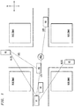
- FIG. 1 is a schematic representation of an orthogonal, four-way intersection between a first street running in the east-west (EW) direction and a second street running in the north-south (NS) direction where there are four vehicles V1, V2, V4, and V6 traveling towards the intersection on the EW street and two vehicles V3 and V5 traveling towards the intersection on the NS street.
- EW east-west
- NS north-south
- each conforming vehicle has a dedicated short-range communications (DSRC) onboard unit (OBU) with an omni-antenna that intermittently transmits a basic safety message (BSM) indicating its identity and current location, heading, and speed.
- DSRC dedicated short-range communications
- BSM basic safety message
- each vehicle's OBU monitors the appropriate wireless transmission link to determine if another vehicle's OBU is already transmitting a BSM. When the link is quiet, each OBU with a BSM to transmit will wait for a randomly selected back-off duration before deciding to begin transmitting its BSM, but only if the link is still quiet.
- vehicle V1 located at all four corners of the intersection are high-rise buildings that block some of the vehicles from having direct lines of sight (LOS) to each other.
- LOS direct lines of sight
- vehicle V1 has a direct LOS to each of vehicles V2, V4, and V6, but not to vehicles V3 and V5 due to the intervening buildings.
- vehicle V1 has "no direct line of sight" (NLOS) to vehicles V3 and V5.
- NLOS no direct line of sight
- V3 Since there is NLOS between vehicles V1 and V3, there is no guarantee that V3 will receive a BSM transmitted by V1. Similarly, there is no guarantee that V5 will receive V1's BSM. By the same token, there is no guarantee that V1 will receive either V3's or V5's BSMs. Although not indicated in FIG. 1 , there are other pairs of vehicles with NLOS between them, such as vehicles V3 and V4 and vehicles V4 and V5.
- the center of the intersection includes a road side unit (RSU).
- the RSU may be mounted above the surface of the intersection such as on a support structure for a traffic light. Since the RSU has a direct LOS with each of the six vehicles VI-V6, the RSU receives all of the BSMs transmitted by vehicles VI-V6.
- the RSU uses at least the identity, location, and heading information in the received BSMs, along with preprogrammed information about the configurations of the buildings at the four corners of the intersection, to identify (using straightforward geometry) pairs of vehicles that have NLOSs between them.
- the BSM also uses speed information from the BSMs in its processing.
- Knowing which pairs of vehicles have NLOSs between them enables the RSU to identify BSMs that need to be retransmitted. For example, the RSU will determine that V1 and V3 have NLOS between them and that V1 and V5 also have NLOS between them, so the RSU will determine that it must retransmit a BSM received from V1 so that V3 and V5 will receive V1's BSM. By the same token, the RSU knows that it must retransmit V3's and V5's BSMs so that V1 will receive them.
- V1 and V3 may end up transmitting their respective BSMs concurrently because they may each misinterpret a quiet communication link as indicating freedom to transmit.
- the RSU will receive two overlapping (in time) BSMs from two different vehicles. Note that, for the orthogonal, four-way intersection of FIG. 1 , since each vehicle has a direct LOS with at least those vehicles currently located on the same street and will therefore not transmit a BSM if any other vehicle on its street is already transmitting a BSM, no more than two vehicles will ever transmit overlapping BSMs.
- the RSU has two omni-antennas and two receive (RX) filters that enable the RSU to receive and successfully recover two overlapping BSMs.
- RX receive
- FIG. 2 is a schematic block diagram of an RSU 200 that can be used as the RSU of FIG. 1 , according to one embodiment of the present invention.
- the RSU 200 includes first and second omni-antennas 210 and 220 and a signal processor 230 that receives first and second receive (RX) signals 212 and 222 from the antennas 210 and 220, and generates up to four transmit (TX) signals 262, 264, 272, and 274 for transmission by the antennas.
- RX receive
- TX transmit
- the signal processor 230 includes first and second receive (RX) filters 240 and 250, a first transmit (TX) filter 260, an (optional) second TX filter 270, a beamforming controller 280, and a relay transceiver 290.
- the beamforming controller 280 generates control signals 282 that specify weighting vectors w 1 - w 4 respectively applied by the filters 240, 250, 260, and 270, as described further below.
- the relay transceiver 290 determines which BSMs to retransmit and generates appropriate outgoing signals 292 and 294 that are provided to the two TX filters 260 and 270 based on the BSMs selected for retransmission.
- the two omni-antennas 210 and 220 are separated by a distance that is substantially equal to one half the wavelength of the signals used to transmit the BSMs.
- the antennas 210 and 220 are separated by a distance in the range of about 2.53cm to about 2.56cm.
- the two antennas 210 and 220 are oriented parallel to one of the two streets ( i.e., either the EW street or the NS street in FIG. 1 ).
- the first and second weighting vectors w 1 and w 2 for the first and second RX filters 240 and 250 can be configured to achieve two different beam-patterns that are substantially mutually orthogonal to one another.
- the third weighting vector w 3 enables the first TX filter 260 to generate an omnidirectional beam-pattern.
- the third and fourth weighting vectors w 3 and w 4 enable the first and second TX filters 260 and 270 to achieve beam-patterns that are substantially mutually orthogonal to one another.
- this same beam-pattern can be generated by either the first TX filter 260 or the second TX filter 270 by setting its weighting vector to have the same values.
- the beam-pattern can be used to retransmit BSMs that will be seen only by vehicles on the NS street.
- this same beam-pattern can be generated by either the first TX filter 260 or the second TX filter 270 by setting its weighting vector to have the same values.
- the beam-pattern can be used to retransmit BSMs that will be seen only by vehicles on the EW street.
- the RSU 200 can recover two overlapping BSMs, where one BSM is transmitted by a vehicle on the NS street of FIG. 1 , and the other BSM is transmitted by a vehicle on the EW street.
- the RSU 200 can recover a BSM from vehicle V1 of FIG. 1 and a BSM from vehicle V3 of FIG. 1 , even when these two vehicles transmit concurrently.
- the relay transceiver 290 is able to receive all of the BSMs from all of the vehicles.
- the relay transceiver 290 then processes the received BSMs to determine which BSMs need to be retransmitted so that they will be received by vehicles having NLOS with the corresponding transmitting vehicles.
- the beamforming performed by the RX and TX filters 240, 250, 260, and 270 can be implemented, for example, using a software-defined radio (SDR) or a hardware-based phase shifting and combining circuit.
- SDR software-defined radio
- the RSU 200 can employ a number of different techniques to retransmit a BSM.
- the RSU 200 retransmits a BSM using an omnidirectional beam-pattern.
- the RSU 200 if the RSU 200 recovers two overlapping BSMs, then the RSU 200 then will transmit the two BSMs sequentially to avoid overlap at the receiving vehicles, when performing the omnidirectional retransmission technique.
- the RSU 200 can retransmit the BSM to vehicles located on the EW street using the beam-pattern of FIG. 4 .
- the RSU 200 can retransmit two different BSMs sequentially by configuring the first TX filter 260 to have the beam-pattern of FIG. 3 and the second TX filter 270 to have the beam-pattern of FIG. 4 , or vice versa.
- the RSU 200 can sequentially retransmit V1's BSM using the beam-pattern of FIG. 3 and V3's BSM using the beam-pattern of FIG. 4 , whether or not those two BSMs were overlapping when received by the RSU 200.
- the transmission link may be available for a vehicle on the NS street to concurrently transmit its own BSM, and vice versa.
- enabling the RSU 200 to transmit directionally on different streets can increase the availability of timeslots which can be used by OBUs on the vehicles.
- the RSU 200 combines first and second BSMs from different streets using a bit-wise logical exclusive-OR (XOR) operation to generate an XOR message that is transmitted from either only the first antenna 210 or only the second antenna 220 using an omnidirectional beam-pattern.
- the XOR message identifies the first and second vehicles that transmitted the corresponding first and second BSMs.
- a vehicle that receives the XOR message can recover the second BSM from the XOR message by applying another bit-wise XOR operation between the XOR message and a locally stored copy of the first BSM, or vice versa.
- the RSU 200 can generate an XOR message based on V1's BSM and V3's BSM, knowing that those two vehicles have NLOS between them.
- V1 can then recover V3's BSM from the received XOR message by performing an XOR operation between the XOR message and V1's (locally stored) BSM.
- V3 can recover V1's BSM from its received copy of the same XOR message by performing an XOR operation between the XOR message and V3's (locally stored) BSM.
- V5 (which also has NLOS with V1) will have directly received V3's BSM from V3, V5 can also recover V1's BSM from its received copy of that same XOR message by performing an XOR operation between the XOR message and V5's locally stored copy of V3's BSM.
- V4 (which has NLOS with V3) can recover V3's BSM from its received copy of that same XOR message using V4's locally stored copy of V1's BSM.
- V2 (which also has NLOS with V3) of FIG. 1 can also use its locally stored copy of V1's BSM to recover V3's BSM.
- the RSU 200 can generate an analogous XOR message from V4's BSM and V5's BSM to enable V1 and V4 to recover V5's BSM and V3 and V5 to recover V4's BSM.
- V2 (which also has NLOS with V5) can also use its locally stored copy of V4's BSM to recover V5's BSM.
- V2's BSM can be retransmitted using either the omnidirectional or the directional retransmission technique. In this way, XOR messages can be efficiently used to enable all pairs of vehicles having NLOS between them to recover each other's BSMs, thereby reducing timeslots used by the RSU 200 for retransmissions.
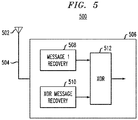
- FIG. 5 is a schematic block diagram of an onboard unit (OBU) 500 for vehicles, such as the vehicles VI-V6 of FIG. 1 .
- the OBU 500 contains an omni-antenna 502 and a transceiver 506 connected by a hardwired signal path 504.
- the transceiver 506 generates (and stores) BSMs for transmission by the antenna 502 in a memory (not shown).
- the antenna 502 receives and the transceiver 506 processes and stores BSMs transmitted by other vehicles and XOR messages transmitted by an RSU, like the RSU 200 of FIG. 2 .
- the transceiver 506 For an XOR message formed from first and second BSMs, if the transceiver 506 has a stored copy of the first BSM (whether the first BSM is its own BSM or a BSM received from another vehicle), then the transceiver 506 can perform an XOR operation between the XOR message and the first BSM to recover the second BSM, and vice versa. Accordingly, in one embodiment, the transceiver 506 includes a first message recovery module 508, a XOR message recovery unit 510, and a XOR gate 512. The transceiver 506 recovers, from the RX signals, a first message from a first vehicle using the module 508.
- the transceiver 506 recovers, from the RX signals, an XOR message from a Road Side Unit (RSU) using the XOR message recovery unit 510. Further, the transceiver 506 performs an XOR operation on the XOR message using the XOR gate 512, based on the first message, to recover a second message from a second vehicle.
- RSU Road Side Unit
- the RSU 200 can reduce retransmissions even further by applying other criteria to the vehicles. For example, even though a first vehicle might not have a direct LOS with a second vehicle based on the geometry of an intersection, in some situations, the second vehicle may still be able to successfully receive a BSM from the first vehicle, and vice versa.
- the BSM signals may sufficiently diffract around the edge of a building at the corner of an intersection to enable two vehicles having NLOS to receive each other's BSMs.
- the transceiver 290 of FIG. 2 can be configured to filter out such BSMs from being retransmitted by taking into account the relevant geometries.
- the transceiver 290 determines that the transmitting vehicle is closer than a specified minimum threshold distance (e.g., 40m) from the center of the intersection, then the transceiver 290 can ignore that BSM for its retransmission processing.
- a specified minimum threshold distance e.g. 40m
- the transceiver 290 can be configured to filter out BSMs from being retransmitted even if there is NLOS between two vehicles if at least one of the vehicles is sufficiently far away from the center of the intersection in distance. For example, if, using a BSM's location information, the transceiver 290 determines that the transmitting vehicle is farther than a specified maximum threshold distance (e.g., 150m) from the center of the intersection, then the transceiver 290 can ignore that BSM for its retransmission processing.
- a specified maximum threshold distance e.g. 150m
- the transceiver 290 can be configured to filter out BSMs from being retransmitted even if there is NLOS between two vehicles if at least one of the vehicles is sufficiently far away from the center of the intersection in time. For example, if, using a BSM's location, heading, and speed information, the transceiver 290 determines that the transmitting vehicle is farther than a specified maximum threshold duration (e.g., about 3 sec) from the center of the intersection, then the transceiver 290 can ignore that BSM for its retransmission processing.
- a specified maximum threshold duration e.g., about 3 sec
- the transceiver 290 determines that a first vehicle is relatively close in distance to the intersection (e.g., within 150m)
- the transceiver 290 determines that the first vehicle is moving sufficiently slowly or not moving at all
- the transceiver 290 can ignore that first vehicle's BSM in its retransmission processing. Note, however, that, if a second vehicle is traveling on the orthogonal street, the transceiver 290 may still determine to retransmit the second vehicle's BSM for receipt by the first vehicle.
- the invention has been described in the context of an RSU having two omni-antennas that can generate substantially mutually orthogonal beam-patterns, those skilled in the art will understand that, in general, the invention can be implemented using two or more antennas, where zero, one, or more of the antennas are omni-antennas and the rest are directional (e.g., cardioid or hypercardioid) antennas, where, depending on their number, the antennas may be configured in one-, two-, or even three-dimensional patterns.
- such RSUs may have two or more RX filters to process RX signals from the antennas and two or more TX filters generate TX signals for the antennas.
- Such RSUs may be able to achieve concurrent beamforming in two or more different directions.
- BSMs basic safety messages
- CAMs cooperative awareness messages
- the RX filters 240 and 250 and the TX filter(s) 260 (and 270) have fixed beam-patterns. In those implementations, the beamforming controller 280 can be omitted. In some implementations, the RX filters 240 and 250 have fixed (e.g., directional) beam-patterns, but the TX filter(s) 260 (and 270) have controllable beam-patterns. In those implementations, the beamforming controller 280 controls weighting vectors for the TX filters, but not for the RX filters.
- Embodiments of the invention can be manifest in the form of methods and apparatuses for practicing those methods, including in the form of program code embodied in tangible media, such as various types of memory devices, including memory connected to servers or local memories of processors, wherein, when the program code is loaded into and executed by a processor, the processor becomes an apparatus for practicing the invention.
- Any suitable processor-usable/readable or computer-usable/readable storage medium may be utilized.
- the storage medium may be (without limitation) an electronic, magnetic, optical, electromagnetic, infrared, or semiconductor system, apparatus, or device.
- DSP digital signal processor
- ASIC application specific integrated circuit
- FPGA field programmable gate array
- ROM read only memory
- any switches shown in the figures are conceptual only. Their function may be carried out through the operation of program logic, through dedicated logic, through the interaction of program control and dedicated logic, or even manually, the particular technique being selectable by the implementer as more specifically understood from the context.
- any block diagrams herein represent conceptual views of illustrative circuitry embodying the principles of the invention.
- any flow charts, flow diagrams, state transition diagrams, pseudo code, and the like represent various processes which may be substantially represented in computer readable medium and so executed by a computer or processor, whether or not such computer or processor is explicitly shown.
- Coupled refers to any manner known in the art or later developed in which energy is allowed to be transferred between two or more elements, and the interposition of one or more additional elements is contemplated, although not required.
- the terms “directly coupled,” “directly connected,” etc. imply the absence of such additional elements.
Landscapes
- Engineering & Computer Science (AREA)
- Computer Networks & Wireless Communication (AREA)
- Signal Processing (AREA)
- Physics & Mathematics (AREA)
- General Physics & Mathematics (AREA)
- Mobile Radio Communication Systems (AREA)
Abstract
Description
- The present invention relates to vehicle-to-vehicle (V2V) communications systems, and, more particularly, to message relaying using road side units (RSUs) in such systems.
- In V2V communications systems that conform to the IEEE 802.11p standard, vehicles transmit basic safety messages (BSMs) to inform other vehicles of their current location, heading, and speed in order to avoid accidents. RSUs are used in V2V communication systems to relay messages between vehicles that do not have a direct line-of-sight (LOS) between them. Such RSUs are provisioned with two omnidirectional (omni) antennas that are located as far apart as possible in order to enable reception diversity at the RSU. Such omni-antennas are separated by a distance equal to multiples of the signal wavelength used to transmit the messages. For systems conforming to the IEEE 802.11p standard, the signal wavelength is in the range of about 5.06cm to about 5.12cm, so the two antennas are typically tens of cm apart in a conventional RSU.
- It would be advantageous to have an efficient circuit to transmit and decode BSMs transmitted by RSUs.
- The invention, together with objects and advantages thereof, may best be understood by reference to the following description of the presently preferred embodiments together with the accompanying drawings in which:
-
FIG. 1 is a schematic diagram of an orthogonal, four-way intersection; -
FIG. 2 is a schematic block diagram of a road side unit (RSU) for the intersection ofFIG. 1 according to one embodiment of the present invention; -
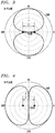
FIG. 3 is a graphic representation of a north-south beam-pattern for the intersection ofFIG. 1 ; -
FIG. 4 is a graphic representation of an east-west beam-pattern for the intersection ofFIG. 1 ; and -
FIG. 5 is a schematic block diagram of an onboard unit (OBU) for each vehicle inFIG. 1 , in accordance with an embodiment of the present invention. - One aspect of the present invention is a road side unit (RSU) for a vehicle-to-vehicle (V2V) communication system. The RSU comprises first and second antennas that both concurrently receive a first message from a first vehicle and a second message from a second vehicle and generate respective first and second receive (RX) signals; and a signal processor that performs spatial filtering to recover (i) the first message from the first and second RX signals using a first directional beam-pattern and (ii) the second message from the first and second RX signals using a second directional beam-pattern that is not parallel to the first directional beam-pattern. The signal processor generates at least a first transmit (TX) signal for the first antenna to enable the second vehicle to receive the first message and the first vehicle to receive the second message.
- Another aspect of the present invention is an onboard unit (OBU) for a V2V communication system. The OBU comprises an antenna that generates RX signals and a transceiver that receives the RX signals from the antenna. The transceiver recovers, from the RX signals, a first message from a first vehicle, and an XOR message from an RSU; and the transceiver performs an XOR operation on the XOR message based on the first message to recover a second message from a second vehicle.
-
FIG. 1 is a schematic representation of an orthogonal, four-way intersection between a first street running in the east-west (EW) direction and a second street running in the north-south (NS) direction where there are four vehicles V1, V2, V4, and V6 traveling towards the intersection on the EW street and two vehicles V3 and V5 traveling towards the intersection on the NS street. - According to the IEEE 802.11p standard, each conforming vehicle has a dedicated short-range communications (DSRC) onboard unit (OBU) with an omni-antenna that intermittently transmits a basic safety message (BSM) indicating its identity and current location, heading, and speed. In order to avoid packet collisions, each vehicle's OBU monitors the appropriate wireless transmission link to determine if another vehicle's OBU is already transmitting a BSM. When the link is quiet, each OBU with a BSM to transmit will wait for a randomly selected back-off duration before deciding to begin transmitting its BSM, but only if the link is still quiet.
- As indicated in
FIG. 1 , located at all four corners of the intersection are high-rise buildings that block some of the vehicles from having direct lines of sight (LOS) to each other. For example, vehicle V1 has a direct LOS to each of vehicles V2, V4, and V6, but not to vehicles V3 and V5 due to the intervening buildings. Thus, vehicle V1 has "no direct line of sight" (NLOS) to vehicles V3 and V5. - Since there is NLOS between vehicles V1 and V3, there is no guarantee that V3 will receive a BSM transmitted by V1. Similarly, there is no guarantee that V5 will receive V1's BSM. By the same token, there is no guarantee that V1 will receive either V3's or V5's BSMs. Although not indicated in
FIG. 1 , there are other pairs of vehicles with NLOS between them, such as vehicles V3 and V4 and vehicles V4 and V5. - To enable pairs of vehicles that have NLOS between them to exchange BSMs, the center of the intersection includes a road side unit (RSU). For example, the RSU may be mounted above the surface of the intersection such as on a support structure for a traffic light. Since the RSU has a direct LOS with each of the six vehicles VI-V6, the RSU receives all of the BSMs transmitted by vehicles VI-V6. The RSU uses at least the identity, location, and heading information in the received BSMs, along with preprogrammed information about the configurations of the buildings at the four corners of the intersection, to identify (using straightforward geometry) pairs of vehicles that have NLOSs between them. As explained further below, in some implementations, the BSM also uses speed information from the BSMs in its processing.
- Knowing which pairs of vehicles have NLOSs between them enables the RSU to identify BSMs that need to be retransmitted. For example, the RSU will determine that V1 and V3 have NLOS between them and that V1 and V5 also have NLOS between them, so the RSU will determine that it must retransmit a BSM received from V1 so that V3 and V5 will receive V1's BSM. By the same token, the RSU knows that it must retransmit V3's and V5's BSMs so that V1 will receive them.
- Furthermore, because V1 and V3 have NLOS between them, V1 and V3 may end up transmitting their respective BSMs concurrently because they may each misinterpret a quiet communication link as indicating freedom to transmit. In that case, the RSU will receive two overlapping (in time) BSMs from two different vehicles. Note that, for the orthogonal, four-way intersection of
FIG. 1 , since each vehicle has a direct LOS with at least those vehicles currently located on the same street and will therefore not transmit a BSM if any other vehicle on its street is already transmitting a BSM, no more than two vehicles will ever transmit overlapping BSMs. - To address the problem of overlapping BSMs, in one embodiment, the RSU has two omni-antennas and two receive (RX) filters that enable the RSU to receive and successfully recover two overlapping BSMs.
-
FIG. 2 is a schematic block diagram of an RSU 200 that can be used as the RSU ofFIG. 1 , according to one embodiment of the present invention. The RSU 200 includes first and second omni-antennas 210 and 220 and asignal processor 230 that receives first and second receive (RX)signals antennas 210 and 220, and generates up to four transmit (TX)signals - The
signal processor 230 includes first and second receive (RX)filters filter 260, an (optional)second TX filter 270, abeamforming controller 280, and arelay transceiver 290. Thebeamforming controller 280 generatescontrol signals 282 that specify weighting vectors w 1 - w 4 respectively applied by thefilters relay transceiver 290 determines which BSMs to retransmit and generates appropriateoutgoing signals TX filters - The
first RX filter 240 receives the first andsecond RX signals second antennas 210 and 220, and applies spatial filtering based on the first weighting vector w 1 to generate a first incoming beam-pattern signal 242 for thetransceiver 290, such that:
- b 1 is the first incoming beam-
pattern signal 242; - r 1 is the
first RX signal 212; - r 2 is the
second RX signal 222; and - w 1 = [w 11 w 12].
- Similarly, the
second RX filter 250 receives the first andsecond RX signals pattern signal 252 for thetransceiver 290, such that:
- b 2 is the second incoming beam-
pattern signal 252; and - w 2 = [w 21 w 22].
- The
first TX filter 260 receives the firstoutgoing signal 292 from therelay transceiver 290 and uses the third weighting vector w 3 to generate afirst TX signal 262 for the first antenna 210 and asecond TX signal 264 for thesecond antenna 220, such that:

- y 1 is the
first TX signal 262; - y 2 is the
second TX signal 264; - s 1 is the first transceiver
outgoing signal 292; and - w 3 = [w 31 w 32].
- If the
second TX filter 270 is included, thesecond TX filter 270 receives the secondoutgoing signal 294 from therelay transceiver 290 and uses the fourth weighting vector w 4 to generate athird TX signal 272 for the first antenna 210 and afourth TX signal 274 for thesecond antenna 220, such that:

- y 3 is the
third TX signal 272; - y 4 is the
fourth TX signal 274; - s 2 is the second transceiver
outgoing signal 294; and - w 4 = [w 41 w 42].
- In certain embodiments, the two omni-
antennas 210 and 220 are separated by a distance that is substantially equal to one half the wavelength of the signals used to transmit the BSMs. In systems that conform to the IEEE 802.11p standard, theantennas 210 and 220 are separated by a distance in the range of about 2.53cm to about 2.56cm. In certain embodiments for orthogonal, four-way intersections, such as the intersection ofFIG. 1 , the twoantennas 210 and 220 are oriented parallel to one of the two streets (i.e., either the EW street or the NS street inFIG. 1 ). - Based on the separation and orientation of the two
antennas 210 and 220, the first and second weighting vectors w 1 and w 2 for the first and second RX filters 240 and 250 can be configured to achieve two different beam-patterns that are substantially mutually orthogonal to one another. The third weighting vector w 3 enables thefirst TX filter 260 to generate an omnidirectional beam-pattern. Alternatively, the third and fourth weighting vectors w 3 and w 4 enable the first and second TX filters 260 and 270 to achieve beam-patterns that are substantially mutually orthogonal to one another. -
FIG. 3 is a graphic representation of the beam-pattern in the horizontal (H) plane generated by thefirst RX filter 240 by setting w 1 = [w 11 w 12] = [1 1] when the twoantennas 210 and 220 are oriented parallel to the EW street, where east is 0 degree, north is 90 degrees, west is 180 degrees, and south is 270 degrees. With its north and south look directions and nulls in the east and west directions, this beam-pattern will see BSMs transmitted by vehicles located on the NS street, but not BSMs transmitted by vehicles located on the EW street. Note that, alternatively, this same beam-pattern can be generated by thesecond RX filter 250 by setting w 2 = [w 21 w 22] = [1 1]. Furthermore, this same beam-pattern can be generated by either thefirst TX filter 260 or thesecond TX filter 270 by setting its weighting vector to have the same values. In that case, the beam-pattern can be used to retransmit BSMs that will be seen only by vehicles on the NS street. -
FIG. 4 is a graphic representation of the beam-pattern in the H-plane generated by thesecond RX filter 250 by setting w 2 = [w 21 w 22] = [1 -1] when the twoantennas 210 and 220 are oriented parallel to the EW street. With its east and west look directions and nulls in the north and south directions, this beam-pattern will see BSMs transmitted by vehicles located on the EW street, but not BSMs transmitted by vehicles located on the NS street. Note that, alternatively, this same beam-pattern can be generated by thefirst RX filter 240 by setting w 1 = [w 11 w 12] = [1 -1]. Furthermore, this same beam-pattern can be generated by either thefirst TX filter 260 or thesecond TX filter 270 by setting its weighting vector to have the same values. In that case, the beam-pattern can be used to retransmit BSMs that will be seen only by vehicles on the EW street. - With the first and second RX filters 240 and 250 configured to generate the beam-patterns of
FIGS. 3 and 4 , the RSU 200 can recover two overlapping BSMs, where one BSM is transmitted by a vehicle on the NS street ofFIG. 1 , and the other BSM is transmitted by a vehicle on the EW street. For example, the RSU 200 can recover a BSM from vehicle V1 ofFIG. 1 and a BSM from vehicle V3 ofFIG. 1 , even when these two vehicles transmit concurrently. - By appropriately configuring the first and second RX filters 240 and 250 as described above, the
relay transceiver 290 is able to receive all of the BSMs from all of the vehicles. Therelay transceiver 290 then processes the received BSMs to determine which BSMs need to be retransmitted so that they will be received by vehicles having NLOS with the corresponding transmitting vehicles. - The beamforming performed by the RX and
TX filters - In an omnidirectional retransmission technique, the RSU 200 retransmits a BSM using an omnidirectional beam-pattern. This can be achieved using the
first TX filter 260 by setting w 3 = [w 31 w 32] = [1 0] or [0 1], such that the first outgoing signal 292 (containing the BSM) is transmitted by only the first omni-antenna 210 or only the second omni-antenna 220. Note further that, alternatively, thesecond TX filter 270 could be used to transmit the BSM in the secondoutgoing signal 294 by setting w 4 = [w 41 w 42] = [1 0] or [0 1]. Either way, each vehicle will receive the retransmitted BSM. - Note that, if the RSU 200 recovers two overlapping BSMs, then the RSU 200 then will transmit the two BSMs sequentially to avoid overlap at the receiving vehicles, when performing the omnidirectional retransmission technique.
- In a directional retransmission technique, the RSU 200 retransmits a BSM using a directional beam-pattern. For example, if the BSM was received from a vehicle on the EW street of
FIG. 1 , then the RSU 200 can retransmit the BSM to vehicles located on the NS street using the beam-pattern ofFIG. 3 . This can be achieved using either thefirst TX filter 260 with w 3 = [w 31 w 32] = [1 1] or thesecond TX filter 270 with w 4 = [w 41 w 42] = [1 1]. - If, on the other hand, the BSM was received from a vehicle on the NS street of
FIG. 1 , then the RSU 200 can retransmit the BSM to vehicles located on the EW street using the beam-pattern ofFIG. 4 . This can be achieved using either thefirst TX filter 260 with w 3 = [w 31 w 32] = [1 -1] or thesecond TX filter 270 with w 4 = [w 41 w 42] = [1 -1]. - Note that, using the directional retransmission technique, the RSU 200 can retransmit two different BSMs sequentially by configuring the
first TX filter 260 to have the beam-pattern ofFIG. 3 and thesecond TX filter 270 to have the beam-pattern ofFIG. 4 , or vice versa. For example, the RSU 200 can sequentially retransmit V1's BSM using the beam-pattern ofFIG. 3 and V3's BSM using the beam-pattern ofFIG. 4 , whether or not those two BSMs were overlapping when received by the RSU 200. When the RSU 200 transmits a BSM using a directional beam-pattern aligned with the EW street, then the transmission link may be available for a vehicle on the NS street to concurrently transmit its own BSM, and vice versa. As such, enabling the RSU 200 to transmit directionally on different streets can increase the availability of timeslots which can be used by OBUs on the vehicles. - In an XOR retransmission technique, the RSU 200 combines first and second BSMs from different streets using a bit-wise logical exclusive-OR (XOR) operation to generate an XOR message that is transmitted from either only the first antenna 210 or only the
second antenna 220 using an omnidirectional beam-pattern. The XOR message identifies the first and second vehicles that transmitted the corresponding first and second BSMs. A vehicle that receives the XOR message can recover the second BSM from the XOR message by applying another bit-wise XOR operation between the XOR message and a locally stored copy of the first BSM, or vice versa. - For example, the RSU 200 can generate an XOR message based on V1's BSM and V3's BSM, knowing that those two vehicles have NLOS between them. V1 can then recover V3's BSM from the received XOR message by performing an XOR operation between the XOR message and V1's (locally stored) BSM. Similarly, V3 can recover V1's BSM from its received copy of the same XOR message by performing an XOR operation between the XOR message and V3's (locally stored) BSM.
- In addition, because V5 (which also has NLOS with V1) will have directly received V3's BSM from V3, V5 can also recover V1's BSM from its received copy of that same XOR message by performing an XOR operation between the XOR message and V5's locally stored copy of V3's BSM. In an analogous manner, V4 (which has NLOS with V3) can recover V3's BSM from its received copy of that same XOR message using V4's locally stored copy of V1's BSM. Note that V2 (which also has NLOS with V3) of
FIG. 1 can also use its locally stored copy of V1's BSM to recover V3's BSM. - In an analogous manner, the RSU 200 can generate an analogous XOR message from V4's BSM and V5's BSM to enable V1 and V4 to recover V5's BSM and V3 and V5 to recover V4's BSM. Note that V2 (which also has NLOS with V5) can also use its locally stored copy of V4's BSM to recover V5's BSM. Note that, while the BSMs from V1, V3, V4, and V5 can be retransmitted using as few as two XOR messages, V2's BSM can be retransmitted using either the omnidirectional or the directional retransmission technique. In this way, XOR messages can be efficiently used to enable all pairs of vehicles having NLOS between them to recover each other's BSMs, thereby reducing timeslots used by the RSU 200 for retransmissions.
-
FIG. 5 is a schematic block diagram of an onboard unit (OBU) 500 for vehicles, such as the vehicles VI-V6 ofFIG. 1 . TheOBU 500 contains an omni-antenna 502 and atransceiver 506 connected by ahardwired signal path 504. Thetransceiver 506 generates (and stores) BSMs for transmission by theantenna 502 in a memory (not shown). In addition, theantenna 502 receives and thetransceiver 506 processes and stores BSMs transmitted by other vehicles and XOR messages transmitted by an RSU, like the RSU 200 ofFIG. 2 . For an XOR message formed from first and second BSMs, if thetransceiver 506 has a stored copy of the first BSM (whether the first BSM is its own BSM or a BSM received from another vehicle), then thetransceiver 506 can perform an XOR operation between the XOR message and the first BSM to recover the second BSM, and vice versa. Accordingly, in one embodiment, thetransceiver 506 includes a firstmessage recovery module 508, a XORmessage recovery unit 510, and aXOR gate 512. Thetransceiver 506 recovers, from the RX signals, a first message from a first vehicle using themodule 508. Thetransceiver 506 recovers, from the RX signals, an XOR message from a Road Side Unit (RSU) using the XORmessage recovery unit 510. Further, thetransceiver 506 performs an XOR operation on the XOR message using theXOR gate 512, based on the first message, to recover a second message from a second vehicle. - The RSU 200 can reduce retransmissions even further by applying other criteria to the vehicles. For example, even though a first vehicle might not have a direct LOS with a second vehicle based on the geometry of an intersection, in some situations, the second vehicle may still be able to successfully receive a BSM from the first vehicle, and vice versa. For example, the BSM signals may sufficiently diffract around the edge of a building at the corner of an intersection to enable two vehicles having NLOS to receive each other's BSMs. The
transceiver 290 ofFIG. 2 can be configured to filter out such BSMs from being retransmitted by taking into account the relevant geometries. In one possible implementation, if, using a BSM's location information, thetransceiver 290 determines that the transmitting vehicle is closer than a specified minimum threshold distance (e.g., 40m) from the center of the intersection, then thetransceiver 290 can ignore that BSM for its retransmission processing. - In addition or instead, the
transceiver 290 can be configured to filter out BSMs from being retransmitted even if there is NLOS between two vehicles if at least one of the vehicles is sufficiently far away from the center of the intersection in distance. For example, if, using a BSM's location information, thetransceiver 290 determines that the transmitting vehicle is farther than a specified maximum threshold distance (e.g., 150m) from the center of the intersection, then thetransceiver 290 can ignore that BSM for its retransmission processing. - In addition or instead, the
transceiver 290 can be configured to filter out BSMs from being retransmitted even if there is NLOS between two vehicles if at least one of the vehicles is sufficiently far away from the center of the intersection in time. For example, if, using a BSM's location, heading, and speed information, thetransceiver 290 determines that the transmitting vehicle is farther than a specified maximum threshold duration (e.g., about 3 sec) from the center of the intersection, then thetransceiver 290 can ignore that BSM for its retransmission processing. Thus, even if thetransceiver 290 determines that a first vehicle is relatively close in distance to the intersection (e.g., within 150m), if thetransceiver 290 determines that the first vehicle is moving sufficiently slowly or not moving at all, then thetransceiver 290 can ignore that first vehicle's BSM in its retransmission processing. Note, however, that, if a second vehicle is traveling on the orthogonal street, thetransceiver 290 may still determine to retransmit the second vehicle's BSM for receipt by the first vehicle. - Other aspects and advantages of the present invention will become apparent from the following description, taken in conjunction with the accompanying drawings, illustrating by way of example the principles of the invention.
- Although the invention has been described in the context of particular weighting vectors and particular beam-patterns, those skilled in the art will understand that other suitable weighting vectors can be used to generate similar or alternative beam-patterns.
- Although the invention has been described in the context of an RSU located at an intersection of two streets having BSM-obstructing buildings at one or more corners of the intersection, those skilled in the art will understand that the invention can be implemented in other suitable situations in which vehicles have NLOS between them, such as around curves with adjacent structures like buildings or hillsides that prevent direct LOSs.
- Although the invention has been described in the context of an RSU having two omni-antennas that can generate substantially mutually orthogonal beam-patterns, those skilled in the art will understand that, in general, the invention can be implemented using two or more antennas, where zero, one, or more of the antennas are omni-antennas and the rest are directional (e.g., cardioid or hypercardioid) antennas, where, depending on their number, the antennas may be configured in one-, two-, or even three-dimensional patterns. In general, such RSUs may have two or more RX filters to process RX signals from the antennas and two or more TX filters generate TX signals for the antennas. Such RSUs may be able to achieve concurrent beamforming in two or more different directions.
- Although the invention has been described in the context of basic safety messages (BSMs) of the IEEE 802.11p standard, those skilled in the art will understand that other suitable messages can be used, such as cooperative awareness messages (CAMs) of the IEEE 802.11p standard. Those skilled in the art also will understand that the invention is not limited to systems that conform to the IEEE 802.11p standard.
- In some implementations, the RX filters 240 and 250 and the TX filter(s) 260 (and 270) have fixed beam-patterns. In those implementations, the
beamforming controller 280 can be omitted. In some implementations, the RX filters 240 and 250 have fixed (e.g., directional) beam-patterns, but the TX filter(s) 260 (and 270) have controllable beam-patterns. In those implementations, thebeamforming controller 280 controls weighting vectors for the TX filters, but not for the RX filters. - It should be apparent to those skilled in the art that the present invention may be embodied in many other specific forms without departing from the spirit or scope of the invention. Particularly, it should be understood that the present invention may be embodied in the following forms.
- Embodiments of the invention can be manifest in the form of methods and apparatuses for practicing those methods, including in the form of program code embodied in tangible media, such as various types of memory devices, including memory connected to servers or local memories of processors, wherein, when the program code is loaded into and executed by a processor, the processor becomes an apparatus for practicing the invention. Any suitable processor-usable/readable or computer-usable/readable storage medium may be utilized. The storage medium may be (without limitation) an electronic, magnetic, optical, electromagnetic, infrared, or semiconductor system, apparatus, or device.
- The functions of the various elements shown in the figures may be provided through the use of dedicated hardware as well as hardware capable of executing software in association with appropriate software. When provided by a processor, the functions may be provided by a single dedicated processor, by a single shared processor, or by a plurality of individual processors, some of which may be shared. Moreover, explicit use of the terms "filter," "subsystem," "transceiver," and "controller" should not be construed to refer exclusively to hardware capable of executing software, and may implicitly include, without limitation, digital signal processor (DSP) hardware, network processor, application specific integrated circuit (ASIC), field programmable gate array (FPGA), read only memory (ROM) for storing software, random access memory (RAM), and nonvolatile storage. Other hardware, conventional and/or custom, may also be included. Similarly, any switches shown in the figures are conceptual only. Their function may be carried out through the operation of program logic, through dedicated logic, through the interaction of program control and dedicated logic, or even manually, the particular technique being selectable by the implementer as more specifically understood from the context.
- It should be appreciated by those of ordinary skill in the art that any block diagrams herein represent conceptual views of illustrative circuitry embodying the principles of the invention. Similarly, it will be appreciated that any flow charts, flow diagrams, state transition diagrams, pseudo code, and the like represent various processes which may be substantially represented in computer readable medium and so executed by a computer or processor, whether or not such computer or processor is explicitly shown.
- Unless explicitly stated otherwise, each numerical value and range should be interpreted as being approximate as if the word "about" or "approximately" preceded the value or range.
- Signals and corresponding terminals, nodes, ports, or paths may be referred to by the same name and are interchangeable for purposes here. For purposes of this description, the terms "couple," "coupling," "coupled," "connect," "connecting," or "connected" refer to any manner known in the art or later developed in which energy is allowed to be transferred between two or more elements, and the interposition of one or more additional elements is contemplated, although not required. Conversely, the terms "directly coupled," "directly connected," etc., imply the absence of such additional elements.
- The present examples and embodiments are to be considered as illustrative and not restrictive, and the invention is not to be limited to the details given herein, but may be modified within the scope and equivalence of the appended claims.
Claims (15)
- A road side unit, RSU, for a vehicle-to-vehicle, V2V, communication system, the RSU comprising:first and second antennas (210, 220) that both are configured to concurrently receive a first message from a first vehicle (V2) and a second message from a second vehicle (V3) and to generate respective first and second receive, RX, signals (212, 222); anda signal processor (230) that is configured to perform spatial filtering to recover (i) the first message from the first and second RX signals (212, 222) using a first directional beam-pattern and (ii) the second message from the first and second RX signals (212, 222) using a second directional beam-pattern that is not parallel to the first directional beam-pattern, wherein the signal processor (230) is configured to generate at least a first transmit (TX) signal (260) for the first antenna (210) to enable the second vehicle (V3) to receive the first message and the first vehicle (V2) to receive the second message.
- The RSU of claim 1, wherein the signal processor comprises:a first RX filter (240) that is configured to combine the first and second RX signals (212, 222) based on the first directional beam-pattern to generate a first incoming beam-pattern signal (242);a second RX filter (250) that is configured to combine the first and second RX signals (212, 222) based on the second directional beam-pattern to generate a second incoming beam-pattern signal (252);a transceiver (506) that is configured to recover (i) the first message from the first incoming beam-pattern signal (242) and (ii) the second message from the second incoming beam-pattern signal (252), wherein:the transceiver (506) is configured to determine that the first message is to be retransmitted for receipt by the second vehicle (V3) and that the second message is to be retransmitted for receipt by the first vehicle (V2); andthe transceiver (506) is configured to generate at least a first outgoing signal (292) based on at least the first message; anda first TX filter (260) that is configured to generate at least the first TX signal for the first antenna based on the first outgoing signal (292).
- The RSU of claim 2, wherein:the transceiver (506) is configured to generate that first outgoing signal (292) as an XOR message by combining the first and second messages using an XOR operation; andthe first TX filter (260) is configured to generate the first TX signal based on the first outgoing signal (292) for the first antenna (210) to transmit the XOR message in an omnidirectional beam-pattern.
- The RSU of claim 3, wherein the first TX filter (260) is configured to generate only the first TX signal for the first antenna based on the first outgoing signal (292) in order to transmit the XOR message in the omnidirectional beam-pattern.
- The RSU of any one of the claims 2 to 4, wherein:the transceiver (506) is configured to initially generate an initial first outgoing signal (292) based on the first message and the first TX filter (260) generates only the first TX signal for the first antenna (210) based on the initial first outgoing signal (292) in order to transmit the first message in the omnidirectional beam-pattern; andthe transceiver (506) is configured to subsequently generate a subsequent first outgoing signal based on the second message and the first TX filter (260) generates only the first TX signal for the first antenna (210) based on the subsequent first outgoing signal in order to transmit the second message in the omnidirectional beam-pattern.
- The RSU of any one of the claims 2 to 5, wherein the signal processor further comprises a second TX filter (270), wherein:the first TX filter (260) is configured to generate, based on the first outgoing signal (292), (i) the first TX signal for the first antenna (210) and (ii) a second TX signal (264) for the second antenna (220);the second TX filter (270) is configured to generate, based on the second outgoing signal (294), (i) a third TX signal (272) for the first antenna (210) and (ii) a fourth TX signal (274) for the second antenna (220).
- The RSU of claim 6, wherein the transceiver (506) is configured to generate the first and second outgoing signals (292, 294) such that the first and second antennas (210, 220) transmit (i) the first message using the second directional beam-pattern and (ii) the second message using the first directional beam-pattern.
- The RSU of claim 6 or claim 7, wherein:the transceiver (506) is configured to generate the first outgoing signal (292) for the first directional beam-pattern based on the second message, but not based on the first message; andthe transceiver (506) is configured to generate the second outgoing signal (294) for the second directional beam-pattern based on the first message, but not based on the second message.
- The RSU of any one of the claims 2 to 8, wherein the signal processor (230) further comprises a beamforming controller (280) that is configured to control a beam-pattern applied by the first TX filter (260).
- The RSU of claim 9, wherein the beamforming controller (280) is configured to control the first directional beam-pattern applied by the first RX filter (240) and the second directional beam-pattern applied by the second RX filter (250).
- The RSU of any preceding claim, wherein:the first and second antennas (210, 220) are separated by a distance substantially equal to one half the signal wavelength of the first and second messages as received at the first and second antennas (210, 220);the first and second antennas (210, 220) are aligned along the first directional beam-pattern;the first and second antennas (210, 220) are omnidirectional antennas;the first and second directional beam-patterns are mutually orthogonal; andeach message is either a basic safety message, BSM, or a cooperative awareness message, CAM, conforming to an IEEE 802.11p standard.
- The RSU of any preceding claim, wherein the RSU is configured to sequentially transmit the first and second messages in an omnidirectional beam-pattern.
- The RSU of any preceding claim, wherein the signal processor (230) is configured to determine that
a third message from a third vehicle is to be retransmitted for receipt by a fourth vehicle based on the signal processor (230) determining that the fourth vehicle cannot reliably receive the third message directly from the third vehicle; and/or
the fourth vehicle cannot reliably receive the third message directly from the third vehicle based on the current locations of the third and fourth vehicles and knowledge of adjacent structures that prevent direct line of sight between the third and fourth vehicles. - The RSU of claim 13, wherein the signal processor (230) is configured to select the third message based on the signal processor (230) determining that
the third vehicle is located greater than a minimum threshold distance from the RSU and less than a maximum threshold distance from the RSU; and/or
the third vehicle is located less than a maximum threshold duration from the RSU. - An onboard unit, OBU, for a Vehicle-to-Vehicle, V2V, communication system, the OBU comprising:an antenna that generates RX signals; anda transceiver (506) that receives the RX signals from the antenna (210), wherein:the transceiver (506) recovers, from the RX signals, a first message from a first vehicle (V2);the transceiver (506) recovers, from the RX signals, an XOR message from a Road Side Unit, RSU; andthe transceiver (506) performs an XOR operation on the XOR message, based on the first message, to recover a second message from a second vehicle (V3).
Applications Claiming Priority (1)
| Application Number | Priority Date | Filing Date | Title |
|---|---|---|---|
| US16/049,769 US10701534B2 (en) | 2018-07-30 | 2018-07-30 | Message relaying in vehicle-to-vehicle communication system |
Publications (1)
| Publication Number | Publication Date |
|---|---|
| EP3605872A1 true EP3605872A1 (en) | 2020-02-05 |
Family
ID=67137525
Family Applications (1)
| Application Number | Title | Priority Date | Filing Date |
|---|---|---|---|
| EP19182701.3A Withdrawn EP3605872A1 (en) | 2018-07-30 | 2019-06-26 | Message relaying in vehicle-to-vehicle communication system |
Country Status (3)
| Country | Link |
|---|---|
| US (1) | US10701534B2 (en) |
| EP (1) | EP3605872A1 (en) |
| CN (1) | CN110784851B (en) |
Families Citing this family (9)
| Publication number | Priority date | Publication date | Assignee | Title |
|---|---|---|---|---|
| US11170640B2 (en) * | 2019-05-14 | 2021-11-09 | Ford Global Technologies, Llc | Method and apparatus for bridging and optimizing V2X networks |
| US11368826B2 (en) * | 2020-01-27 | 2022-06-21 | Ford Global Technologies, Llc | Method and apparatus for bridging and optimizing V2X networks in vehicles |
| CN111489589B (en) * | 2020-04-15 | 2022-04-05 | 中车青岛四方机车车辆股份有限公司 | A vehicle anti-collision method, device, equipment and storage medium |
| CN111917830A (en) * | 2020-07-02 | 2020-11-10 | 南昌工程学院 | Method and system for vehicle communication in Internet of vehicles |
| CN112887937B (en) * | 2021-01-10 | 2022-10-21 | 之江实验室 | Terminal equipment video information cooperative uploading method based on roadside equipment assistance |
| US12366632B2 (en) * | 2021-09-21 | 2025-07-22 | Qualcomm Incorporated | Assisting node radar assistance |
| US12279210B2 (en) * | 2021-11-18 | 2025-04-15 | Qualcomm Incorporated | Roadside unit message transmission management |
| US20240064498A1 (en) * | 2022-08-18 | 2024-02-22 | Qualcomm Incorporated | Directional wireless message transmission |
| US12133079B2 (en) * | 2022-09-30 | 2024-10-29 | Ford Global Technologies, Llc | Pre-security message verification |
Citations (3)
| Publication number | Priority date | Publication date | Assignee | Title |
|---|---|---|---|---|
| US20070121521A1 (en) * | 2005-11-30 | 2007-05-31 | D Amico Thomas V | Method and apparatus for broadcast in an AD HOC network with dynamic selection of relay nodes |
| US20120213173A1 (en) * | 2011-02-22 | 2012-08-23 | Qualcomm Incorporated | System and method for third-party assisted peer-to-peer communication |
| WO2018125686A2 (en) * | 2016-12-30 | 2018-07-05 | Intel Corporation | Methods and devices for radio communications |
Family Cites Families (17)
| Publication number | Priority date | Publication date | Assignee | Title |
|---|---|---|---|---|
| KR20000036179A (en) | 1996-09-16 | 2000-06-26 | 스콧이. 랜시크 | Antenna system for enhancing the coverage area, range and reliability of wireless base stations |
| WO2005017854A1 (en) | 2003-08-19 | 2005-02-24 | Philips Intellectual Property & Standards Gmbh | Method of receiving messages transmitted from vehicle to vehicle |
| US20070088464A1 (en) | 2005-10-13 | 2007-04-19 | Coates Keven D | Apparatus and method for inter-vehicle communication |
| EP1784032A1 (en) | 2005-11-04 | 2007-05-09 | Alcatel Lucent | Method for performing user allocation in SDMA systems, and corresponding base station |
| US8923147B2 (en) | 2011-10-03 | 2014-12-30 | Qualcomm Incorporated | Method and apparatus for filtering and processing received vehicle peer transmissions based on reliability information |
| KR101420529B1 (en) * | 2012-12-10 | 2014-07-17 | 경북대학교 산학협력단 | Method and system for vehicular communication of beacon message using network coding |
| WO2015019234A1 (en) * | 2013-08-05 | 2015-02-12 | Universidade De Aveiro | Method and apparatus for multi-network communication in vehicular networks |
| US9306639B2 (en) * | 2014-07-29 | 2016-04-05 | Nxp, B.V. | Cooperative antenna-diversity radio receiver |
| JP6547061B2 (en) | 2015-08-31 | 2019-07-17 | ノキア ソリューションズ アンド ネットワークス オサケ ユキチュアNokia Solutions and Networks Oy | Wireless communication setup in wireless assisted road traffic management scenario |
| US10321353B2 (en) * | 2015-09-23 | 2019-06-11 | Electronics And Telecommunications Research Institute | Operation methods of communication node supporting direct communications in network |
| US9843550B2 (en) | 2015-11-29 | 2017-12-12 | International Business Machines Corporation | Processing messages in a data messaging system using constructed resource models |
| US10321461B2 (en) * | 2016-05-06 | 2019-06-11 | Bridgewest Finance Llc | Unmanned aerial vehicle (UAV) beam pointing and data rate optimization for high throughput broadband access |
| US10424197B2 (en) * | 2016-08-10 | 2019-09-24 | Futurewei Technologies, Inc. | Apparatus, computer program, and method for supporting vehicle-to-vehicle communication utilizing a base station |
| CN108235222B (en) * | 2016-12-12 | 2019-09-17 | 电信科学技术研究院 | A kind of method and apparatus sending data |
| US10073464B2 (en) * | 2016-12-30 | 2018-09-11 | Bendix Commercial Vehicle Systems Llc | Varying the distance between vehicles in a platoon |
| US11272426B2 (en) * | 2017-05-26 | 2022-03-08 | Qualcomm Incorporated | Techniques for directional discovery in millimeter wave communications system |
| EP4239905A3 (en) * | 2018-03-30 | 2023-10-18 | Comcast Cable Communications LLC | Configuration for beam failure recovery |
-
2018
- 2018-07-30 US US16/049,769 patent/US10701534B2/en active Active
-
2019
- 2019-06-26 EP EP19182701.3A patent/EP3605872A1/en not_active Withdrawn
- 2019-07-30 CN CN201910699615.0A patent/CN110784851B/en not_active Expired - Fee Related
Patent Citations (3)
| Publication number | Priority date | Publication date | Assignee | Title |
|---|---|---|---|---|
| US20070121521A1 (en) * | 2005-11-30 | 2007-05-31 | D Amico Thomas V | Method and apparatus for broadcast in an AD HOC network with dynamic selection of relay nodes |
| US20120213173A1 (en) * | 2011-02-22 | 2012-08-23 | Qualcomm Incorporated | System and method for third-party assisted peer-to-peer communication |
| WO2018125686A2 (en) * | 2016-12-30 | 2018-07-05 | Intel Corporation | Methods and devices for radio communications |
Non-Patent Citations (2)
| Title |
|---|
| KE DONG ET AL: "Adaptive antenna selection and Tx/Rx beamforming for large-scale MIMO systems in 60 GHz channels", EURASIP JOURNAL ON WIRELESS COMMUNICATIONS AND NETWORKING, vol. 2011, no. 1, 1 January 2011 (2011-01-01), pages 59, XP055313320, ISSN: 1687-1499, DOI: 10.1186/1687-1499-2011-59 * |
| NOOR-A-RAHIM MD ET AL: "Performance Analysis of IEEE 802.11p Safety Message Broadcast With and Without Relaying at Road Intersection", IEEE ACCESS, vol. 6, 16 May 2018 (2018-05-16), pages 23786 - 23799, XP011683779, DOI: 10.1109/ACCESS.2018.2829897 * |
Also Published As
| Publication number | Publication date |
|---|---|
| US20200037131A1 (en) | 2020-01-30 |
| US10701534B2 (en) | 2020-06-30 |
| CN110784851B (en) | 2023-11-14 |
| CN110784851A (en) | 2020-02-11 |
Similar Documents
| Publication | Publication Date | Title |
|---|---|---|
| US10701534B2 (en) | Message relaying in vehicle-to-vehicle communication system | |
| US10862576B2 (en) | Transmitter and relay communication devices for D2D communication | |
| CN110139323B (en) | Method and device for load distribution in a communication system supporting V2X | |
| US20190281644A1 (en) | Base station and transmitter and relay communication devices for cellular and d2d communication | |
| CN107454552B (en) | Apparatus and method for relay station for vehicle-to-vehicle messages | |
| Bazzi et al. | A distributed virtual traffic light algorithm exploiting short range V2V communications | |
| US10637620B2 (en) | Communication device, base station and communication method | |
| CN111630933A (en) | Method and apparatus for performing sidelink communications by a UE in NR V2X | |
| CN104768131B (en) | A kind of relay node alarm information retransmission method based on truck traffic | |
| CN113273309A (en) | Side link failure recovery with beamforming | |
| EP2980998A1 (en) | Cooperative antenna-diversity radio receiver | |
| JPWO2020022399A1 (en) | Base station and its control method | |
| Na et al. | Congestion control vs. link failure: TCP behavior in mmWave connected vehicular networks | |
| CN113196822B (en) | Terminal device, base station, method and recording medium | |
| JP5736980B2 (en) | Roadside communication device, wireless communication system, wireless signal receiving method, and computer program | |
| KR20170036623A (en) | Operation method of communication node supporting direct communication in network | |
| JP2024517827A (en) | Inter-UE coordination request signal in inter-vehicle communication | |
| JP2008283567A (en) | Communication system and roadside communication device | |
| JP2008288820A (en) | Wireless communication system | |
| KR101935230B1 (en) | Method and apparatus for message relaying | |
| JPWO2020100204A1 (en) | V2X on-board unit and V2X repeater | |
| WO2025092522A1 (en) | User equipment and method of signal reception and resource allocation in sidelink communication | |
| KR102179098B1 (en) | vehicle-to-vehicle communication method based on LTE-TDD | |
| Klapez et al. | IEEE 802.11 p field trials on interference minimization for safety-related V2X applications | |
| JP5418648B2 (en) | Wireless communication method and system |
Legal Events
| Date | Code | Title | Description |
|---|---|---|---|
| PUAI | Public reference made under article 153(3) epc to a published international application that has entered the european phase |
Free format text: ORIGINAL CODE: 0009012 |
|
| STAA | Information on the status of an ep patent application or granted ep patent |
Free format text: STATUS: THE APPLICATION HAS BEEN PUBLISHED |
|
| AK | Designated contracting states |
Kind code of ref document: A1 Designated state(s): AL AT BE BG CH CY CZ DE DK EE ES FI FR GB GR HR HU IE IS IT LI LT LU LV MC MK MT NL NO PL PT RO RS SE SI SK SM TR |
|
| AX | Request for extension of the european patent |
Extension state: BA ME |
|
| STAA | Information on the status of an ep patent application or granted ep patent |
Free format text: STATUS: REQUEST FOR EXAMINATION WAS MADE |
|
| 17P | Request for examination filed |
Effective date: 20200805 |
|
| RBV | Designated contracting states (corrected) |
Designated state(s): AL AT BE BG CH CY CZ DE DK EE ES FI FR GB GR HR HU IE IS IT LI LT LU LV MC MK MT NL NO PL PT RO RS SE SI SK SM TR |
|
| STAA | Information on the status of an ep patent application or granted ep patent |
Free format text: STATUS: EXAMINATION IS IN PROGRESS |
|
| 17Q | First examination report despatched |
Effective date: 20210608 |
|
| STAA | Information on the status of an ep patent application or granted ep patent |
Free format text: STATUS: THE APPLICATION HAS BEEN WITHDRAWN |
|
| 18W | Application withdrawn |
Effective date: 20211008 |