EP3605836A1 - Motor control system and input/output device - Google Patents
Motor control system and input/output device Download PDFInfo
- Publication number
- EP3605836A1 EP3605836A1 EP17903576.1A EP17903576A EP3605836A1 EP 3605836 A1 EP3605836 A1 EP 3605836A1 EP 17903576 A EP17903576 A EP 17903576A EP 3605836 A1 EP3605836 A1 EP 3605836A1
- Authority
- EP
- European Patent Office
- Prior art keywords
- motor
- input
- motor control
- output device
- control apparatus
- Prior art date
- Legal status (The legal status is an assumption and is not a legal conclusion. Google has not performed a legal analysis and makes no representation as to the accuracy of the status listed.)
- Granted
Links
Images
Classifications
-
- H—ELECTRICITY
- H02—GENERATION; CONVERSION OR DISTRIBUTION OF ELECTRIC POWER
- H02P—CONTROL OR REGULATION OF ELECTRIC MOTORS, ELECTRIC GENERATORS OR DYNAMO-ELECTRIC CONVERTERS; CONTROLLING TRANSFORMERS, REACTORS OR CHOKE COILS
- H02P29/00—Arrangements for regulating or controlling electric motors, appropriate for both AC and DC motors
- H02P29/40—Regulating or controlling the amount of current drawn or delivered by the motor for controlling the mechanical load
-
- G—PHYSICS
- G05—CONTROLLING; REGULATING
- G05B—CONTROL OR REGULATING SYSTEMS IN GENERAL; FUNCTIONAL ELEMENTS OF SUCH SYSTEMS; MONITORING OR TESTING ARRANGEMENTS FOR SUCH SYSTEMS OR ELEMENTS
- G05B19/00—Program-control systems
- G05B19/02—Program-control systems electric
- G05B19/18—Numerical control [NC], i.e. automatically operating machines, in particular machine tools, e.g. in a manufacturing environment, so as to execute positioning, movement or co-ordinated operations by means of program data in numerical form
- G05B19/19—Numerical control [NC], i.e. automatically operating machines, in particular machine tools, e.g. in a manufacturing environment, so as to execute positioning, movement or co-ordinated operations by means of program data in numerical form characterised by positioning or contouring control systems, e.g. to control position from one programmed point to another or to control movement along a programmed continuous path
- G05B19/21—Numerical control [NC], i.e. automatically operating machines, in particular machine tools, e.g. in a manufacturing environment, so as to execute positioning, movement or co-ordinated operations by means of program data in numerical form characterised by positioning or contouring control systems, e.g. to control position from one programmed point to another or to control movement along a programmed continuous path using an incremental digital measuring device
-
- G—PHYSICS
- G05—CONTROLLING; REGULATING
- G05B—CONTROL OR REGULATING SYSTEMS IN GENERAL; FUNCTIONAL ELEMENTS OF SUCH SYSTEMS; MONITORING OR TESTING ARRANGEMENTS FOR SUCH SYSTEMS OR ELEMENTS
- G05B2219/00—Program-control systems
- G05B2219/20—Pc systems
- G05B2219/21—Pc I-O input output
- G05B2219/21063—Bus, I-O connected to a bus
Definitions
- the present disclosure relates to a motor control system and an input and output device.
- Patent Literature 1 discloses a system in which a plurality of sensors are connected to an interface unit through respective communication paths, and a detection signal of each of the sensors is transmitted to a host controller or a motor control apparatus via a network that connects the host controller and the motor control apparatus to each other.
- Patent Literature 2 discloses a system in which a peripheral device that sets a parameter of a motor control apparatus or performs monitoring of the motor control apparatus through a communication unit in the motor control apparatus is connected.
- the present disclosure has been made in consideration of the above circumstances, and an object of the present disclosure is to provide a motor control system and an input and output device, in which it is possible to reduce a physical or processing cost.
- the first aspect of the present disclosure is summarized as a motor control system including: a mechanical apparatus configured to be driven by a motor; a position detector configured to detect position information of the motor; a motor control apparatus configured to control the motor; one or a plurality of sensors configured to detect information relating to at least any one of the mechanical apparatus and the motor; and an input and output device including a plurality of input-and-output connectors, wherein the position detector and the input and output device are configured to be connected to the motor control apparatus through a same communication path, the sensor is configured to be connected to the input-and-output connector of the input and output device, the position information is configured to be transmitted from the position detector to the motor control apparatus, and the information relating to at least any one of the mechanical apparatus and the motor is configured to be transmitted from the sensor to the motor control apparatus through the input and output device.
- the second aspect of the present disclosure is summarized as an input and output device used in a motor control system, the device including: a plurality of input-and-output connectors configured to be connected to one or a plurality of sensors configured to detect information relating to at least any one of a motor and a mechanical apparatus configured to be driven by the motor, wherein the input and output device is configured to be connected to a motor control apparatus through a same communication path as a communication path of a position detector configured to detect position information of the motor, and the input and output device is configured to transmit the information relating to at least any one of the mechanical apparatus and the motor, which has been acquired from the sensor, to the motor control apparatus through the communication path.
- sensing of an operation situation in a motor control system has become more important in recent years.
- a physical cost for the number of wires and the like and a processing cost for traffic, processing loads, and the like increase.
- the costs tend to increase.
- the motor control system 1 includes a mechanical apparatus 10A, a motor 10, a motor control apparatus 20, an encoder 30, an input and output device 40, and a plurality of sensors 501 to 506.
- the motor control apparatus 20 is configured to control the motor 10.
- the motor control apparatus 20 is a device including a computer that controls an amplifier unit that outputs a current, a voltage, and the like to the motor 10. That is, the motor 10 is configured to rotate in accordance with the voltage or the current applied from the motor control apparatus 20.
- the mechanical apparatus 10A is configured to be driven by the motor 10. For example, a robot corresponds to the mechanical apparatus 10A.
- the motor control apparatus 20 that controls a servomotor is called as a servo-controller, a servo-amplifier, or the like.
- the motor control apparatus 20 may be a device configured to control the motor 10, for example, may be an inverter.
- the encoder 30 is a position detector configured to detect position information of the motor 10.
- the encoder 30 may be an optical encoder or a magnetic encoder, for example.
- the encoder 30 is configured to transmit the position information of the motor 10 to the motor control apparatus 20.
- a case using the encoder 30 as the position detector is described as an example.
- the present disclosure can be applied to a case using a sensor (for example, resolver) capable of detecting the position information of the motor 10.
- the encoder 30 may be a linear scale (linear encoder) used in a case where the motor 10 is a linear motor.
- the motor 10 may be a rotary motor or a linear motor.
- the above-described position information indicates a rotation angle.
- the above-described position information indicates a linear position.
- the input and output device 40 includes a plurality of input-and-output connectors #1 to #8 and is a general-purpose input and output unit that connects the sensors 501 to 506 and the like to other peripheral devices.
- the input and output device 40 is used for increasing an input-and-output connector which has been insufficient in the motor control system 1.
- the input and output device 40 is configured to transmit information to the motor control apparatus 20.
- the information relates to at least any one of the mechanical apparatus 10A and the motor 10 and is input from peripheral devices connected to the input-and-output connectors #1 to #8.
- the plurality of sensors 501 to 506 is configured to detect the information relating to at least any one of the mechanical apparatus 10A and the motor 10.
- a temperature sensor, a pressure sensor, a torque sensor, a vibration sensor, a limit switch sensor, a touch sensor, and an I/O device are assumed as the plurality of sensors.
- the temperature sensor is a sensor configured to detect the temperature of at least any one of the mechanical apparatus 10A and the motor 10 or the temperature in the vicinity of the mechanical apparatus 10A or the motor 10.
- a temperature measuring resistor type sensor or a thermocouple type sensor may be used as the temperature sensor.
- the pressure sensor is a sensor configured to detect the pressure of at least any one of the mechanical apparatus 10A and the motor 10 or the pressure in the vicinity of the mechanical apparatus 10A or the motor 10.
- the pressure sensor is configured to measure the pressure with a pressure-sensitive element through a diaphragm (a stainless steel diaphragm, a silicon diaphragm, or the like) and to convert the measured pressure into an electrical signal and output the electrical signal.
- the torque sensor is a sensor configured to detect a torque of at least any one of the mechanical apparatus 10A and the motor 10.
- the torque sensor may be a non-contact type torque sensor or a contact type torque sensor.
- the information relating to the motor 10 means information which is not position information of the motor 10 among types of information regarding the state of the motor 10.
- the information relating to at least any one of the mechanical apparatus 10A and the motor 10 is information changing in accordance with the state of at least any one of the mechanical apparatus 10A and the motor 10. For example, this information may be information which can be detected by the sensors 501 to 506.
- the information relating to the motor 10 is information of the torque of the motor 10, the temperature of the motor 10, a position of an object such as an arm, which is moved by the motor 10, pressure on the object, or the state (for example, temperature) of the sensors 501 to 506 that detect the above items.
- the information relating to the motor 10 is used for an output control of the motor 10 or for adjusting a control parameter or is used for determining whether or not a problem occurs in the motor 10 or predicting a lifespan (remaining period) of the motor 10.
- a case where the six sensors 501 to 506 are connected to the input and output device 40 is described as an example.
- the present disclosure can be applied to a case where sensors of which the number is not six are connected to the input and output device 40 or a case where a peripheral device other than the sensor is connected to the input and output device 40.
- communication paths between the encoder 30 and the motor control apparatus 20 and between the input and output device 40 and the motor control apparatus 20 are configured to be the same as each other. That is, in the motor control system 1 according to the embodiment, the motor control apparatus 20, the encoder 30, and the input and output device 40 are configured to be connected in series (daisy chain shape).
- the sensors 501 to 506 is configured to be not connected to the motor control apparatus 20 and but connected to the input-and-output connectors #1 to #8 of the input and output device 40.
- the position information of the motor 10 is configured to be transmitted from the encoder 30 to the motor control apparatus 20.
- the information relating to the motor 10 is configured to be transmitted from the sensors 501 to 506 to the motor control apparatus 20 through the input and output device 40.
- Step S1001 the motor control apparatus 20 transmits "COM" to the encoder 30 and the input and output device 40.
- "COM is data for an instruction to transmit the position information of the motor 10 and the information relating to the motor 10.
- Step S1002 the encoder 30 transmits "RES#1" to the motor control apparatus 20.
- "RES#1" is data including the position information of the motor 10.
- Step S1003 the input and output device 40 acquires the information relating to at least any one of the mechanical apparatus 10A and the motor 10 from the sensors 501 to 506.
- Step S1004 the input and output device 40 generates "RES#2" based on the information relating to at least any one of the mechanical apparatus 10A and the motor 10.
- "RES#2" is data including the information relating to at least any one of the mechanical apparatus 10A and the motor 10.
- the input and output device 40 transmits "RES#2" to the motor control apparatus 20.
- the sensors 501 to 506 may detect the information relating to at least any one of the mechanical apparatus 10A and the motor 10 at a predetermined timing, or may detect the information relating to at least any one of the mechanical apparatus 10A and the motor 10 in accordance with an instruction from the input and output device 40.
- the sensors 501 to 506 may transmit the information relating to at least any one of the mechanical apparatus 10A and the motor 10 to the input and output device 40 at a predetermined timing.
- the sensors 501 to 506 may transmit the information relating to at least any one of the mechanical apparatus 10A and the motor 10 to the input and output device 40 in accordance with the instruction from the input and output device 40.
- Fig. 3 illustrates an example of a format of "RES#2". As illustrated in Fig. 3(a) , the format of "RES#2" has an address portion "A”, a data portion "DT", and a check code portion "CRC”.
- the address portion "A” is configured to store transmission source information of "RES#2".
- the address portion "A” may be configured to store an address of the input and output device 40 that transmits "RES#2", as the transmission source information.
- the address portion "A” may be configured to store destination information of "RES#2". In this case, the address portion "A" may be configured to store an address of the motor control apparatus 20 as the destination information.
- Code information used for detection of an erroneous code in "RES#2" is stored in the check code portion "CRC".
- CRC check code portion
- Various well-known methods can be applied to the erroneous code detection. For example, cyclic redundancy check of any number of bits may be used.
- the data portion "DT" is configured to store the information relating to at least any one of the mechanical apparatus 10A and the motor 10, which has been detected by the sensors 501 to 506, a time point at which the information relating to at least any one of the mechanical apparatus 10A and the motor 10 has been detected, and the like.
- the data portion "DT" may be configured to store “ALM”, “DI (Digital Inputs)", “time stamp”, “DI1 input time point”, “DI2 input time point”, “DI3 input time point”, “DI1 information”, “DI2 information”, and “DI3 information”.
- Alarm codes indicating abnormality information of the input and output device 40 or abnormality information of the sensors 501 to 506 connected to the input and output device 40 are stored in "ALM".
- a flag indicating an input state of the peripheral device such as the sensor, which is connected to the input-and-output connectors #1 to #8 of the input and output device 40 is stored in "DI". For example, in a case where a flag corresponding to the input-and-output connector #1 of the input and output device 40 is "1", the flag indicates that a limit switch sensor connected to the input-and-output connector #1 is in an ON state. In a case where the flag is "0", the flag indicates that the limit switch sensor is in an OFF state.
- the DI1 to DI8 correspond to the input-and-output connectors #1 to #8, and the peripheral device such as the sensor is connected to the input-and-output connectors #1 to #3 (DI1 to DI3).
- Time stamp is configured to store a time point at which "RES#2" has been generated.
- “Time stamp” may be configured to store a time point at which "RES#2" has been transmitted by the input and output device 40, instead of the time point at which "RES#2" has been generated.
- "DI1 input time point” to “DI3 input time point” are configured to store a time point at which the information relating to at least any one of the mechanical apparatus 10A and the motor 10 has been detected by the sensor connected to the input-and-output connectors #1 to #3 of the input and output device 40.
- "DI1 input time point” to “DI3 input time point” may be configured to store a time point at which the information relating to at least any one of the mechanical apparatus 10A and the motor 10, which has been detected by the sensor connected to the input-and-output connectors #1 to #3 of the input and output device 40 has been received by the input and output device 40.
- "DI1 input time point” to "DI3 input time point” are configured to store the information relating to at least any one of the mechanical apparatus 10A and the motor 10, which has been detected by the sensor connected to the input-and-output connectors #1 to #3 of the input and output device 40.
- the input and output device 40 is configured to put the information relating to at least any one of the mechanical apparatus 10A and the motor 10, which has been detected by the plurality of sensors 501 to 506, into "RES#2" and transmit the information to the motor control apparatus 20.
- the plurality of sensors 501 to 506 into "RES#2" and transmit the information to the motor control apparatus 20.
- the motor control system 1 in the embodiment it is possible to reduce the number of wires in the motor control apparatus 20 or the plurality of sensors 501 to 506 configured to detect the information relating to at least any one of the mechanical apparatus 10A and the motor 10.
Landscapes
- Engineering & Computer Science (AREA)
- Human Computer Interaction (AREA)
- Manufacturing & Machinery (AREA)
- Physics & Mathematics (AREA)
- General Physics & Mathematics (AREA)
- Automation & Control Theory (AREA)
- Power Engineering (AREA)
- Control Of Electric Motors In General (AREA)
Abstract
Description
- The present disclosure relates to a motor control system and an input and output device.
-
Patent Literature 1 discloses a system in which a plurality of sensors are connected to an interface unit through respective communication paths, and a detection signal of each of the sensors is transmitted to a host controller or a motor control apparatus via a network that connects the host controller and the motor control apparatus to each other. -
Patent Literature 2 discloses a system in which a peripheral device that sets a parameter of a motor control apparatus or performs monitoring of the motor control apparatus through a communication unit in the motor control apparatus is connected. -
- Patent Literature 1:
JP H8-241111 A - Patent Literature 2:
JP H10-105206 A - However, there is a problem in that each sensor or each peripheral device is connected to a motor control apparatus, and thus a physical or processing cost tends to increase, in the motor control system in the related art.
- The present disclosure has been made in consideration of the above circumstances, and an object of the present disclosure is to provide a motor control system and an input and output device, in which it is possible to reduce a physical or processing cost.
- The first aspect of the present disclosure is summarized as a motor control system including: a mechanical apparatus configured to be driven by a motor; a position detector configured to detect position information of the motor; a motor control apparatus configured to control the motor; one or a plurality of sensors configured to detect information relating to at least any one of the mechanical apparatus and the motor; and an input and output device including a plurality of input-and-output connectors, wherein the position detector and the input and output device are configured to be connected to the motor control apparatus through a same communication path, the sensor is configured to be connected to the input-and-output connector of the input and output device, the position information is configured to be transmitted from the position detector to the motor control apparatus, and the information relating to at least any one of the mechanical apparatus and the motor is configured to be transmitted from the sensor to the motor control apparatus through the input and output device.
- The second aspect of the present disclosure is summarized as an input and output device used in a motor control system, the device including: a plurality of input-and-output connectors configured to be connected to one or a plurality of sensors configured to detect information relating to at least any one of a motor and a mechanical apparatus configured to be driven by the motor, wherein the input and output device is configured to be connected to a motor control apparatus through a same communication path as a communication path of a position detector configured to detect position information of the motor, and the input and output device is configured to transmit the information relating to at least any one of the mechanical apparatus and the motor, which has been acquired from the sensor, to the motor control apparatus through the communication path.
- According to the present disclosure, it is possible to provide motor control system and an input and output device, in which it is possible to reduce a physical or processing cost.
-
-
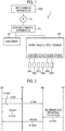
Fig. 1 is a schematic diagram illustrating an example of an overall configuration of a motor control system according to an embodiment. -
Fig. 2 is a diagram illustrating an example of a flow of processing performed in the motor control system according to the embodiment. -
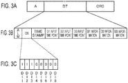
Fig. 3 is a diagram illustrating an example of a format of data used in the motor control system according to the embodiment. - According to the viewpoint of the inventor of the present invention, sensing of an operation situation in a motor control system has become more important in recent years. However, if the number of sensors increases, a physical cost for the number of wires and the like and a processing cost for traffic, processing loads, and the like increase. In particular, in a case where sensing is performed in real time, the costs tend to increase.
- As a result of intensive research and development to reduce the costs in the motor control system, the inventor of the present invention has conceived of a new and unique motor control system. Hereinafter, an example of a
motor control system 1 according to an embodiment will be described with reference toFigs. 1 to 3 . - As illustrated in
Fig. 1 , themotor control system 1 according to the embodiment of the present disclosure includes amechanical apparatus 10A, amotor 10, amotor control apparatus 20, anencoder 30, an input andoutput device 40, and a plurality ofsensors 501 to 506. - The
motor control apparatus 20 is configured to control themotor 10. Specifically, themotor control apparatus 20 is a device including a computer that controls an amplifier unit that outputs a current, a voltage, and the like to themotor 10. That is, themotor 10 is configured to rotate in accordance with the voltage or the current applied from themotor control apparatus 20. Themechanical apparatus 10A is configured to be driven by themotor 10. For example, a robot corresponds to themechanical apparatus 10A. - Generally, the
motor control apparatus 20 that controls a servomotor is called as a servo-controller, a servo-amplifier, or the like. Themotor control apparatus 20 may be a device configured to control themotor 10, for example, may be an inverter. - The
encoder 30 is a position detector configured to detect position information of themotor 10. Theencoder 30 may be an optical encoder or a magnetic encoder, for example. Theencoder 30 is configured to transmit the position information of themotor 10 to themotor control apparatus 20. - In the embodiment, a case using the
encoder 30 as the position detector is described as an example. The present disclosure can be applied to a case using a sensor (for example, resolver) capable of detecting the position information of themotor 10. Here, theencoder 30 may be a linear scale (linear encoder) used in a case where themotor 10 is a linear motor. - The
motor 10 may be a rotary motor or a linear motor. Here, in a case where themotor 10 is a rotary motor, the above-described position information indicates a rotation angle. In a case where themotor 10 is a linear motor, the above-described position information indicates a linear position. - The input and
output device 40 includes a plurality of input-and-output connectors # 1 to #8 and is a general-purpose input and output unit that connects thesensors 501 to 506 and the like to other peripheral devices. The input andoutput device 40 is used for increasing an input-and-output connector which has been insufficient in themotor control system 1. - The input and
output device 40 is configured to transmit information to themotor control apparatus 20. The information relates to at least any one of themechanical apparatus 10A and themotor 10 and is input from peripheral devices connected to the input-and-output connectors # 1 to #8. - The plurality of
sensors 501 to 506 is configured to detect the information relating to at least any one of themechanical apparatus 10A and themotor 10. A temperature sensor, a pressure sensor, a torque sensor, a vibration sensor, a limit switch sensor, a touch sensor, and an I/O device are assumed as the plurality of sensors. - The temperature sensor is a sensor configured to detect the temperature of at least any one of the
mechanical apparatus 10A and themotor 10 or the temperature in the vicinity of themechanical apparatus 10A or themotor 10. For example, a temperature measuring resistor type sensor or a thermocouple type sensor may be used as the temperature sensor. - The pressure sensor is a sensor configured to detect the pressure of at least any one of the
mechanical apparatus 10A and themotor 10 or the pressure in the vicinity of themechanical apparatus 10A or themotor 10. The pressure sensor is configured to measure the pressure with a pressure-sensitive element through a diaphragm (a stainless steel diaphragm, a silicon diaphragm, or the like) and to convert the measured pressure into an electrical signal and output the electrical signal. - The torque sensor is a sensor configured to detect a torque of at least any one of the
mechanical apparatus 10A and themotor 10. For example, the torque sensor may be a non-contact type torque sensor or a contact type torque sensor. - The information relating to the
motor 10 means information which is not position information of themotor 10 among types of information regarding the state of themotor 10. The information relating to at least any one of themechanical apparatus 10A and themotor 10 is information changing in accordance with the state of at least any one of themechanical apparatus 10A and themotor 10. For example, this information may be information which can be detected by thesensors 501 to 506. - For example, the information relating to the
motor 10 is information of the torque of themotor 10, the temperature of themotor 10, a position of an object such as an arm, which is moved by themotor 10, pressure on the object, or the state (for example, temperature) of thesensors 501 to 506 that detect the above items. - The information relating to the
motor 10 is used for an output control of themotor 10 or for adjusting a control parameter or is used for determining whether or not a problem occurs in themotor 10 or predicting a lifespan (remaining period) of themotor 10. - In the embodiment, a case where the six
sensors 501 to 506 are connected to the input andoutput device 40 is described as an example. The present disclosure can be applied to a case where sensors of which the number is not six are connected to the input andoutput device 40 or a case where a peripheral device other than the sensor is connected to the input andoutput device 40. - In the
motor control system 1 according to the embodiment, communication paths between theencoder 30 and themotor control apparatus 20 and between the input andoutput device 40 and themotor control apparatus 20 are configured to be the same as each other. That is, in themotor control system 1 according to the embodiment, themotor control apparatus 20, theencoder 30, and the input andoutput device 40 are configured to be connected in series (daisy chain shape). - In the
motor control system 1 according to the embodiment, thesensors 501 to 506 is configured to be not connected to themotor control apparatus 20 and but connected to the input-and-output connectors # 1 to #8 of the input andoutput device 40. - Here, the position information of the
motor 10 is configured to be transmitted from theencoder 30 to themotor control apparatus 20. The information relating to themotor 10 is configured to be transmitted from thesensors 501 to 506 to themotor control apparatus 20 through the input andoutput device 40. - An example of a flow of processing performed in the
motor control system 1 according to the embodiment will be described below with reference toFigs. 2 and3 . - As illustrated in
Fig. 2 , in Step S1001, themotor control apparatus 20 transmits "COM" to theencoder 30 and the input andoutput device 40. "COM is data for an instruction to transmit the position information of themotor 10 and the information relating to themotor 10. - In Step S1002, the
encoder 30 transmits "RES# 1" to themotor control apparatus 20. "RES# 1" is data including the position information of themotor 10. - In Step S1003, the input and
output device 40 acquires the information relating to at least any one of themechanical apparatus 10A and themotor 10 from thesensors 501 to 506. In Step S1004, the input andoutput device 40 generates "RES# 2" based on the information relating to at least any one of themechanical apparatus 10A and themotor 10. "RES# 2" is data including the information relating to at least any one of themechanical apparatus 10A and themotor 10. The input andoutput device 40 transmits "RES# 2" to themotor control apparatus 20. - Here, the
sensors 501 to 506 may detect the information relating to at least any one of themechanical apparatus 10A and themotor 10 at a predetermined timing, or may detect the information relating to at least any one of themechanical apparatus 10A and themotor 10 in accordance with an instruction from the input andoutput device 40. - Similarly, the
sensors 501 to 506 may transmit the information relating to at least any one of themechanical apparatus 10A and themotor 10 to the input andoutput device 40 at a predetermined timing. Thesensors 501 to 506 may transmit the information relating to at least any one of themechanical apparatus 10A and themotor 10 to the input andoutput device 40 in accordance with the instruction from the input andoutput device 40. -
Fig. 3 illustrates an example of a format of "RES# 2". As illustrated inFig. 3(a) , the format of "RES# 2" has an address portion "A", a data portion "DT", and a check code portion "CRC". - The address portion "A" is configured to store transmission source information of "
RES# 2". For example, the address portion "A" may be configured to store an address of the input andoutput device 40 that transmits "RES# 2", as the transmission source information. - The address portion "A" may be configured to store destination information of "
RES# 2". In this case, the address portion "A" may be configured to store an address of themotor control apparatus 20 as the destination information. - Code information used for detection of an erroneous code in "
RES# 2" is stored in the check code portion "CRC". Various well-known methods can be applied to the erroneous code detection. For example, cyclic redundancy check of any number of bits may be used. - The data portion "DT" is configured to store the information relating to at least any one of the
mechanical apparatus 10A and themotor 10, which has been detected by thesensors 501 to 506, a time point at which the information relating to at least any one of themechanical apparatus 10A and themotor 10 has been detected, and the like. - For example, as illustrated in
Fig. 3(b) , the data portion "DT" may be configured to store "ALM", "DI (Digital Inputs)", "time stamp", "DI1 input time point", "DI2 input time point", "DI3 input time point", "DI1 information", "DI2 information", and "DI3 information". - Alarm codes indicating abnormality information of the input and
output device 40 or abnormality information of thesensors 501 to 506 connected to the input andoutput device 40 are stored in "ALM". - A flag indicating an input state of the peripheral device such as the sensor, which is connected to the input-and-
output connectors # 1 to #8 of the input andoutput device 40 is stored in "DI". For example, in a case where a flag corresponding to the input-and-output connector # 1 of the input andoutput device 40 is "1", the flag indicates that a limit switch sensor connected to the input-and-output connector # 1 is in an ON state. In a case where the flag is "0", the flag indicates that the limit switch sensor is in an OFF state. - In the example in
Fig. 3(c) , the DI1 to DI8 correspond to the input-and-output connectors # 1 to #8, and the peripheral device such as the sensor is connected to the input-and-output connectors # 1 to #3 (DI1 to DI3). - "Time stamp" is configured to store a time point at which "
RES# 2" has been generated. "Time stamp" may be configured to store a time point at which "RES# 2" has been transmitted by the input andoutput device 40, instead of the time point at which "RES# 2" has been generated. - "DI1 input time point" to "DI3 input time point" are configured to store a time point at which the information relating to at least any one of the
mechanical apparatus 10A and themotor 10 has been detected by the sensor connected to the input-and-output connectors # 1 to #3 of the input andoutput device 40. "DI1 input time point" to "DI3 input time point" may be configured to store a time point at which the information relating to at least any one of themechanical apparatus 10A and themotor 10, which has been detected by the sensor connected to the input-and-output connectors # 1 to #3 of the input andoutput device 40 has been received by the input andoutput device 40. - "DI1 input time point" to "DI3 input time point" are configured to store the information relating to at least any one of the
mechanical apparatus 10A and themotor 10, which has been detected by the sensor connected to the input-and-output connectors # 1 to #3 of the input andoutput device 40. - In the embodiment, a case where "DI1 input time point" to "DI3 input time point" and "DI1 information" to "DI3 information" relating to all the sensors connected to the input-and-
output connectors # 1 to #3 of the input andoutput device 40 are stored in the data portion "DT" is described as an example. The present disclosure can be applied to a case where only "DIx input time point" and "DIx information" relating to some of the plurality of sensors connected to the input-and-output connector #x of the input andoutput device 40 are stored in the data portion "DT". - In the
motor control system 1 according to the embodiment, it is possible to randomly set a region of the data portion "DT", in which "DIx input time point" and "DIx information" are stored. - According to the
motor control system 1 in the embodiment, the input andoutput device 40 is configured to put the information relating to at least any one of themechanical apparatus 10A and themotor 10, which has been detected by the plurality ofsensors 501 to 506, into "RES# 2" and transmit the information to themotor control apparatus 20. Thus, connecting the plurality of sensors in a high-speed communication is possible. - According to the
motor control system 1 in the embodiment, it is possible to reduce the number of wires in themotor control apparatus 20 or the plurality ofsensors 501 to 506 configured to detect the information relating to at least any one of themechanical apparatus 10A and themotor 10. -
- 1
- motor control system
- 10
- motor
- 10A
- mechanical apparatus
- 20
- motor control apparatus
- 30
- encoder
- 40
- input and output device
- #1-#8
- input-and-output connector
- 501-506
- sensor
Claims (3)
- A motor control system comprising:a mechanical apparatus configured to be driven by a motor;a position detector configured to detect position information of the motor;a motor control apparatus configured to control the motor;one or a plurality of sensors configured to detect information relating to at least any one of the mechanical apparatus and the motor; andan input and output device including a plurality of input-and-output connectors, whereinthe position detector and the input and output device are configured to be connected to the motor control apparatus through a same communication path,the sensor is configured to be connected to the input-and-output connector of the input and output device,the position information is configured to be transmitted from the position detector to the motor control apparatus, andthe information relating to at least any one of the mechanical apparatus and the motor is configured to be transmitted from the sensor to the motor control apparatus through the input and output device.
- The motor control system according to claim 1, wherein
the input and output device is configured to generate data and transmit the data to the motor control apparatus, the data including the information relating to at least any one of the mechanical apparatus and the motor, which has been detected by the sensor, and a time point at which the information relating to at least one of the mechanical apparatus and the motor has been detected. - An input and output device used in a motor control system, the device comprising:a plurality of input-and-output connectors configured to be connected to one or a plurality of sensors configured to detect information relating to at least any one of a motor and a mechanical apparatus configured to be driven by the motor, whereinthe input and output device is configured to be connected to a motor control apparatus through a same communication path as a communication path of a position detector configured to detect position information of the motor, andthe input and output device is configured to transmit the information relating to at least any one of the mechanical apparatus and the motor, which has been acquired from the sensor, to the motor control apparatus through the communication path.
Applications Claiming Priority (1)
| Application Number | Priority Date | Filing Date | Title |
|---|---|---|---|
| PCT/JP2017/012286 WO2018179030A1 (en) | 2017-03-27 | 2017-03-27 | Motor control system and input/output device |
Publications (3)
| Publication Number | Publication Date |
|---|---|
| EP3605836A1 true EP3605836A1 (en) | 2020-02-05 |
| EP3605836A4 EP3605836A4 (en) | 2020-11-11 |
| EP3605836B1 EP3605836B1 (en) | 2025-10-08 |
Family
ID=63518864
Family Applications (1)
| Application Number | Title | Priority Date | Filing Date |
|---|---|---|---|
| EP17903576.1A Active EP3605836B1 (en) | 2017-03-27 | 2017-03-27 | Motor control system and input/output device |
Country Status (5)
| Country | Link |
|---|---|
| US (1) | US10983497B2 (en) |
| EP (1) | EP3605836B1 (en) |
| JP (1) | JP6388081B1 (en) |
| CN (1) | CN110463029B (en) |
| WO (1) | WO2018179030A1 (en) |
Families Citing this family (1)
| Publication number | Priority date | Publication date | Assignee | Title |
|---|---|---|---|---|
| DE102020104230A1 (en) | 2020-02-18 | 2021-08-19 | Beckhoff Automation Gmbh | Safety module for a secure drive control of a drive system in an automation system, drive system and automation system |
Family Cites Families (10)
| Publication number | Priority date | Publication date | Assignee | Title |
|---|---|---|---|---|
| JP3481339B2 (en) | 1995-03-03 | 2003-12-22 | 三菱電機株式会社 | Drive control system |
| JP3615596B2 (en) * | 1995-08-22 | 2005-02-02 | ファナック株式会社 | Numerical controller |
| JP3439930B2 (en) | 1996-10-02 | 2003-08-25 | 三菱電機株式会社 | Servo motor drive control device and servo amplifier, peripheral device, servo motor position detector |
| US6092618A (en) * | 1997-10-31 | 2000-07-25 | General Motors Corporation | Electro-hydraulic power steering control with fluid temperature and motor speed compensation of power steering load signal |
| JP3772052B2 (en) * | 1999-07-09 | 2006-05-10 | ファナック株式会社 | Control device |
| CN101464693B (en) * | 2007-12-17 | 2010-11-03 | 台达电子工业股份有限公司 | Signal processing device for motor position |
| JP5228578B2 (en) * | 2008-03-31 | 2013-07-03 | 株式会社ジェイテクト | Motor control device and electric power steering device |
| US8072174B2 (en) * | 2008-11-17 | 2011-12-06 | Rockwell Automation Technologies, Inc. | Motor controller with integrated serial interface having selectable synchronization and communications |
| JP2011161649A (en) | 2010-02-04 | 2011-08-25 | Ricoh Co Ltd | Image forming apparatus, servo control device, and program |
| JP6015708B2 (en) * | 2014-05-13 | 2016-10-26 | 株式会社デンソー | Three-phase rotating machine current control system |
-
2017
- 2017-03-27 CN CN201780089009.6A patent/CN110463029B/en active Active
- 2017-03-27 WO PCT/JP2017/012286 patent/WO2018179030A1/en not_active Ceased
- 2017-03-27 EP EP17903576.1A patent/EP3605836B1/en active Active
- 2017-03-27 JP JP2017536034A patent/JP6388081B1/en active Active
-
2019
- 2019-09-27 US US16/585,015 patent/US10983497B2/en active Active
Also Published As
| Publication number | Publication date |
|---|---|
| EP3605836B1 (en) | 2025-10-08 |
| CN110463029A (en) | 2019-11-15 |
| JPWO2018179030A1 (en) | 2019-04-04 |
| EP3605836A4 (en) | 2020-11-11 |
| US20200089186A1 (en) | 2020-03-19 |
| WO2018179030A1 (en) | 2018-10-04 |
| US10983497B2 (en) | 2021-04-20 |
| CN110463029B (en) | 2023-01-20 |
| JP6388081B1 (en) | 2018-09-12 |
Similar Documents
| Publication | Publication Date | Title |
|---|---|---|
| US10072948B2 (en) | Encoder, controller, method for processing data | |
| CN105247816B (en) | Synchronized measurement system | |
| US10454346B2 (en) | Encoder, controller, method for processing data | |
| EP1906154A1 (en) | Circuit for emulating encoder data | |
| US10921108B2 (en) | Method for monitoring a magnetic bearing apparatus | |
| US10274944B2 (en) | Motor control system, control method, encoder, and motor controller | |
| US10983497B2 (en) | Motor control system and input and output device | |
| EP3539221B1 (en) | Slip ring with selective wear indication | |
| CN104412076B (en) | Fluid measurement instrument | |
| JP5037437B2 (en) | Encoder with internal information output function | |
| JP4537438B2 (en) | Encoder and motor control device | |
| US11316461B2 (en) | Motor control apparatus, motor control method, and motor control system | |
| JP5193665B2 (en) | Contactless master controller and failure detection method for contactless master controller | |
| KR20140125909A (en) | Apparatus of interface for multi-sensor device | |
| US20240162791A1 (en) | Sensor System | |
| TW202127157A (en) | Control target device and method for controlling variable physical parameter | |
| CN103714674A (en) | Sensing signal processing method, equipment and system | |
| TWI734334B (en) | Control target device and method for controlling variable physical parameter | |
| CN103646520A (en) | Wireless transmission non-contact pressure detection method | |
| JP2016084176A (en) | Control device, system and library program |
Legal Events
| Date | Code | Title | Description |
|---|---|---|---|
| STAA | Information on the status of an ep patent application or granted ep patent |
Free format text: STATUS: THE INTERNATIONAL PUBLICATION HAS BEEN MADE |
|
| PUAI | Public reference made under article 153(3) epc to a published international application that has entered the european phase |
Free format text: ORIGINAL CODE: 0009012 |
|
| STAA | Information on the status of an ep patent application or granted ep patent |
Free format text: STATUS: REQUEST FOR EXAMINATION WAS MADE |
|
| 17P | Request for examination filed |
Effective date: 20191021 |
|
| AK | Designated contracting states |
Kind code of ref document: A1 Designated state(s): AL AT BE BG CH CY CZ DE DK EE ES FI FR GB GR HR HU IE IS IT LI LT LU LV MC MK MT NL NO PL PT RO RS SE SI SK SM TR |
|
| AX | Request for extension of the european patent |
Extension state: BA ME |
|
| DAV | Request for validation of the european patent (deleted) | ||
| DAX | Request for extension of the european patent (deleted) | ||
| A4 | Supplementary search report drawn up and despatched |
Effective date: 20201009 |
|
| RIC1 | Information provided on ipc code assigned before grant |
Ipc: G05B 19/21 20060101ALN20201005BHEP Ipc: H02P 29/40 20160101AFI20201005BHEP |
|
| STAA | Information on the status of an ep patent application or granted ep patent |
Free format text: STATUS: EXAMINATION IS IN PROGRESS |
|
| 17Q | First examination report despatched |
Effective date: 20220329 |
|
| REG | Reference to a national code |
Ref legal event code: R079 Ipc: H02P0029400000 Ref country code: DE Ref legal event code: R079 Ref document number: 602017092154 Country of ref document: DE Free format text: PREVIOUS MAIN CLASS: H02P0029000000 Ipc: H02P0029400000 |
|
| GRAP | Despatch of communication of intention to grant a patent |
Free format text: ORIGINAL CODE: EPIDOSNIGR1 |
|
| STAA | Information on the status of an ep patent application or granted ep patent |
Free format text: STATUS: GRANT OF PATENT IS INTENDED |
|
| RIC1 | Information provided on ipc code assigned before grant |
Ipc: H02P 29/40 20160101AFI20250616BHEP Ipc: G05B 19/21 20060101ALN20250616BHEP |
|
| INTG | Intention to grant announced |
Effective date: 20250626 |
|
| GRAS | Grant fee paid |
Free format text: ORIGINAL CODE: EPIDOSNIGR3 |
|
| GRAA | (expected) grant |
Free format text: ORIGINAL CODE: 0009210 |
|
| STAA | Information on the status of an ep patent application or granted ep patent |
Free format text: STATUS: THE PATENT HAS BEEN GRANTED |
|
| AK | Designated contracting states |
Kind code of ref document: B1 Designated state(s): AL AT BE BG CH CY CZ DE DK EE ES FI FR GB GR HR HU IE IS IT LI LT LU LV MC MK MT NL NO PL PT RO RS SE SI SK SM TR |
|
| REG | Reference to a national code |
Ref country code: GB Ref legal event code: FG4D Ref country code: CH Ref legal event code: F10 Free format text: ST27 STATUS EVENT CODE: U-0-0-F10-F00 (AS PROVIDED BY THE NATIONAL OFFICE) Effective date: 20251008 |
|
| REG | Reference to a national code |
Ref country code: DE Ref legal event code: R096 Ref document number: 602017092154 Country of ref document: DE |
|
| REG | Reference to a national code |
Ref country code: IE Ref legal event code: FG4D |
|
| REG | Reference to a national code |
Ref country code: NL Ref legal event code: MP Effective date: 20251008 |
|
| REG | Reference to a national code |
Ref country code: AT Ref legal event code: MK05 Ref document number: 1845720 Country of ref document: AT Kind code of ref document: T Effective date: 20251008 |
|
| PG25 | Lapsed in a contracting state [announced via postgrant information from national office to epo] |
Ref country code: NL Free format text: LAPSE BECAUSE OF FAILURE TO SUBMIT A TRANSLATION OF THE DESCRIPTION OR TO PAY THE FEE WITHIN THE PRESCRIBED TIME-LIMIT Effective date: 20251008 |
|
| PG25 | Lapsed in a contracting state [announced via postgrant information from national office to epo] |
Ref country code: ES Free format text: LAPSE BECAUSE OF FAILURE TO SUBMIT A TRANSLATION OF THE DESCRIPTION OR TO PAY THE FEE WITHIN THE PRESCRIBED TIME-LIMIT Effective date: 20251008 |
|
| REG | Reference to a national code |
Ref country code: LT Ref legal event code: MG9D |
|
| PG25 | Lapsed in a contracting state [announced via postgrant information from national office to epo] |
Ref country code: NO Free format text: LAPSE BECAUSE OF FAILURE TO SUBMIT A TRANSLATION OF THE DESCRIPTION OR TO PAY THE FEE WITHIN THE PRESCRIBED TIME-LIMIT Effective date: 20260108 |
|
| PGFP | Annual fee paid to national office [announced via postgrant information from national office to epo] |
Ref country code: DE Payment date: 20260326 Year of fee payment: 10 |
|
| PG25 | Lapsed in a contracting state [announced via postgrant information from national office to epo] |
Ref country code: AT Free format text: LAPSE BECAUSE OF FAILURE TO SUBMIT A TRANSLATION OF THE DESCRIPTION OR TO PAY THE FEE WITHIN THE PRESCRIBED TIME-LIMIT Effective date: 20251008 Ref country code: HR Free format text: LAPSE BECAUSE OF FAILURE TO SUBMIT A TRANSLATION OF THE DESCRIPTION OR TO PAY THE FEE WITHIN THE PRESCRIBED TIME-LIMIT Effective date: 20251008 Ref country code: FI Free format text: LAPSE BECAUSE OF FAILURE TO SUBMIT A TRANSLATION OF THE DESCRIPTION OR TO PAY THE FEE WITHIN THE PRESCRIBED TIME-LIMIT Effective date: 20251008 |
|
| PG25 | Lapsed in a contracting state [announced via postgrant information from national office to epo] |
Ref country code: RS Free format text: LAPSE BECAUSE OF FAILURE TO SUBMIT A TRANSLATION OF THE DESCRIPTION OR TO PAY THE FEE WITHIN THE PRESCRIBED TIME-LIMIT Effective date: 20260108 |
|
| PG25 | Lapsed in a contracting state [announced via postgrant information from national office to epo] |
Ref country code: IS Free format text: LAPSE BECAUSE OF FAILURE TO SUBMIT A TRANSLATION OF THE DESCRIPTION OR TO PAY THE FEE WITHIN THE PRESCRIBED TIME-LIMIT Effective date: 20260208 |
|
| PG25 | Lapsed in a contracting state [announced via postgrant information from national office to epo] |
Ref country code: PT Free format text: LAPSE BECAUSE OF FAILURE TO SUBMIT A TRANSLATION OF THE DESCRIPTION OR TO PAY THE FEE WITHIN THE PRESCRIBED TIME-LIMIT Effective date: 20260209 |
|
| PG25 | Lapsed in a contracting state [announced via postgrant information from national office to epo] |
Ref country code: PL Free format text: LAPSE BECAUSE OF FAILURE TO SUBMIT A TRANSLATION OF THE DESCRIPTION OR TO PAY THE FEE WITHIN THE PRESCRIBED TIME-LIMIT Effective date: 20251008 |
|
| PG25 | Lapsed in a contracting state [announced via postgrant information from national office to epo] |
Ref country code: LV Free format text: LAPSE BECAUSE OF FAILURE TO SUBMIT A TRANSLATION OF THE DESCRIPTION OR TO PAY THE FEE WITHIN THE PRESCRIBED TIME-LIMIT Effective date: 20251008 |
|
| PG25 | Lapsed in a contracting state [announced via postgrant information from national office to epo] |
Ref country code: BG Free format text: LAPSE BECAUSE OF FAILURE TO SUBMIT A TRANSLATION OF THE DESCRIPTION OR TO PAY THE FEE WITHIN THE PRESCRIBED TIME-LIMIT Effective date: 20251008 |