EP3605831A1 - Controlling an electronically-assisted turbocharger - Google Patents
Controlling an electronically-assisted turbocharger Download PDFInfo
- Publication number
- EP3605831A1 EP3605831A1 EP19189445.0A EP19189445A EP3605831A1 EP 3605831 A1 EP3605831 A1 EP 3605831A1 EP 19189445 A EP19189445 A EP 19189445A EP 3605831 A1 EP3605831 A1 EP 3605831A1
- Authority
- EP
- European Patent Office
- Prior art keywords
- phase
- motor
- line
- electric motor
- turbocharger
- Prior art date
- Legal status (The legal status is an assumption and is not a legal conclusion. Google has not performed a legal analysis and makes no representation as to the accuracy of the status listed.)
- Withdrawn
Links
Images

Classifications
-
- H—ELECTRICITY
- H02—GENERATION; CONVERSION OR DISTRIBUTION OF ELECTRIC POWER
- H02P—CONTROL OR REGULATION OF ELECTRIC MOTORS, ELECTRIC GENERATORS OR DYNAMO-ELECTRIC CONVERTERS; CONTROLLING TRANSFORMERS, REACTORS OR CHOKE COILS
- H02P6/00—Arrangements for controlling synchronous motors or other dynamo-electric motors using electronic commutation dependent on the rotor position; Electronic commutators therefor
- H02P6/14—Electronic commutators
- H02P6/16—Circuit arrangements for detecting position
- H02P6/18—Circuit arrangements for detecting position without separate position detecting elements
- H02P6/182—Circuit arrangements for detecting position without separate position detecting elements using back-emf in windings
-
- F—MECHANICAL ENGINEERING; LIGHTING; HEATING; WEAPONS; BLASTING
- F02—COMBUSTION ENGINES; HOT-GAS OR COMBUSTION-PRODUCT ENGINE PLANTS
- F02B—INTERNAL-COMBUSTION PISTON ENGINES; COMBUSTION ENGINES IN GENERAL
- F02B37/00—Engines characterised by provision of pumps driven at least for part of the time by exhaust
- F02B37/12—Control of the pumps
- F02B37/14—Control of the alternation between or the operation of exhaust drive and other drive of a pump, e.g. dependent on speed
-
- F—MECHANICAL ENGINEERING; LIGHTING; HEATING; WEAPONS; BLASTING
- F02—COMBUSTION ENGINES; HOT-GAS OR COMBUSTION-PRODUCT ENGINE PLANTS
- F02B—INTERNAL-COMBUSTION PISTON ENGINES; COMBUSTION ENGINES IN GENERAL
- F02B39/00—Component parts, details, or accessories relating to, driven charging or scavenging pumps, not provided for in groups F02B33/00 - F02B37/00
- F02B39/02—Drives of pumps; Varying pump drive gear ratio
- F02B39/08—Non-mechanical drives, e.g. fluid drives having variable gear ratio
- F02B39/10—Non-mechanical drives, e.g. fluid drives having variable gear ratio electric
-
- F—MECHANICAL ENGINEERING; LIGHTING; HEATING; WEAPONS; BLASTING
- F02—COMBUSTION ENGINES; HOT-GAS OR COMBUSTION-PRODUCT ENGINE PLANTS
- F02C—GAS-TURBINE PLANTS; AIR INTAKES FOR JET-PROPULSION PLANTS; CONTROLLING FUEL SUPPLY IN AIR-BREATHING JET-PROPULSION PLANTS
- F02C6/00—Plural gas-turbine plants; Combinations of gas-turbine plants with other apparatus; Adaptations of gas-turbine plants for special use
- F02C6/04—Gas-turbine plants providing heated or pressurised working fluid for other apparatus, e.g. without mechanical power output
- F02C6/10—Gas-turbine plants providing heated or pressurised working fluid for other apparatus, e.g. without mechanical power output supplying working fluid to a user, e.g. a chemical process, which returns working fluid to a turbine of the plant
- F02C6/12—Turbochargers, i.e. plants for augmenting mechanical power output of internal-combustion piston engines by increase of charge pressure
-
- F—MECHANICAL ENGINEERING; LIGHTING; HEATING; WEAPONS; BLASTING
- F02—COMBUSTION ENGINES; HOT-GAS OR COMBUSTION-PRODUCT ENGINE PLANTS
- F02C—GAS-TURBINE PLANTS; AIR INTAKES FOR JET-PROPULSION PLANTS; CONTROLLING FUEL SUPPLY IN AIR-BREATHING JET-PROPULSION PLANTS
- F02C7/00—Features, components parts, details or accessories, not provided for in, or of interest apart form groups F02C1/00 - F02C6/00; Air intakes for jet-propulsion plants
- F02C7/26—Starting; Ignition
- F02C7/268—Starting drives for the rotor, acting directly on the rotor of the gas turbine to be started
- F02C7/275—Mechanical drives
-
- F—MECHANICAL ENGINEERING; LIGHTING; HEATING; WEAPONS; BLASTING
- F02—COMBUSTION ENGINES; HOT-GAS OR COMBUSTION-PRODUCT ENGINE PLANTS
- F02D—CONTROLLING COMBUSTION ENGINES
- F02D41/00—Electrical control of supply of combustible mixture or its constituents
- F02D41/0002—Controlling intake air
- F02D41/0007—Controlling intake air for control of turbo-charged or super-charged engines
-
- H—ELECTRICITY
- H02—GENERATION; CONVERSION OR DISTRIBUTION OF ELECTRIC POWER
- H02P—CONTROL OR REGULATION OF ELECTRIC MOTORS, ELECTRIC GENERATORS OR DYNAMO-ELECTRIC CONVERTERS; CONTROLLING TRANSFORMERS, REACTORS OR CHOKE COILS
- H02P21/00—Arrangements or methods for the control of electric machines by vector control, e.g. by control of field orientation
- H02P21/14—Estimation or adaptation of machine parameters, e.g. flux, current or voltage
- H02P21/18—Estimation of position or speed
-
- H—ELECTRICITY
- H02—GENERATION; CONVERSION OR DISTRIBUTION OF ELECTRIC POWER
- H02P—CONTROL OR REGULATION OF ELECTRIC MOTORS, ELECTRIC GENERATORS OR DYNAMO-ELECTRIC CONVERTERS; CONTROLLING TRANSFORMERS, REACTORS OR CHOKE COILS
- H02P6/00—Arrangements for controlling synchronous motors or other dynamo-electric motors using electronic commutation dependent on the rotor position; Electronic commutators therefor
- H02P6/14—Electronic commutators
- H02P6/16—Circuit arrangements for detecting position
- H02P6/18—Circuit arrangements for detecting position without separate position detecting elements
- H02P6/188—Circuit arrangements for detecting position without separate position detecting elements using the voltage difference between the windings
-
- F—MECHANICAL ENGINEERING; LIGHTING; HEATING; WEAPONS; BLASTING
- F05—INDEXING SCHEMES RELATING TO ENGINES OR PUMPS IN VARIOUS SUBCLASSES OF CLASSES F01-F04
- F05D—INDEXING SCHEME FOR ASPECTS RELATING TO NON-POSITIVE-DISPLACEMENT MACHINES OR ENGINES, GAS-TURBINES OR JET-PROPULSION PLANTS
- F05D2220/00—Application
- F05D2220/40—Application in turbochargers
-
- F—MECHANICAL ENGINEERING; LIGHTING; HEATING; WEAPONS; BLASTING
- F05—INDEXING SCHEMES RELATING TO ENGINES OR PUMPS IN VARIOUS SUBCLASSES OF CLASSES F01-F04
- F05D—INDEXING SCHEME FOR ASPECTS RELATING TO NON-POSITIVE-DISPLACEMENT MACHINES OR ENGINES, GAS-TURBINES OR JET-PROPULSION PLANTS
- F05D2270/00—Control
- F05D2270/01—Purpose of the control system
- F05D2270/04—Purpose of the control system to control acceleration (u)
- F05D2270/044—Purpose of the control system to control acceleration (u) by making it as high as possible
Definitions
- This disclosure relates to controlling electrical machines, particularly motor generator units (MGUs) used in turbochargers for boosting and energy recovery.
- MGUs motor generator units
- turbochargers are used to increase the power output of internal combustion engines.
- Turbochargers are powered by a turbine within the exhaust manifold of the internal combustion engine.
- the turbine turns a compressor that increases the pressure and total air flow within the intake manifold. Due to inertia of the rotating components and inefficiencies in the turbine, there is a delay between the pressure supplied to the intake manifold and the pressure needed in the intake manifold due to engine load. Such a delay is often referred to as turbo lag.
- some turbochargers include an electrical machine that functions as a booster motor to accelerate the compressor and turbine to a desired speed quicker than the turbo would accelerate on its own. Besides boosting, the electrical machine can also functions as a generator to recover excess exhaust energy from the engine.
- This disclosure describes technologies relating to controlling an electronically-assisted turbocharger.
- An example implementation of the subject matter described within this disclosure is a method of controlling an electrically assisted turbocharger with the following features.
- a first line-to-line terminal voltage of a three-phase electric motor is measured while the three-phase electric motor free-spins.
- a second line-to-line terminal voltage of a three-phase electric motor is measured while the three-phase electric motor free-spins.
- a motor's rotor position is determined based on the first line-to-line terminal voltage and the second line-to-line terminal voltage.
- Three-phase current is sent to the motor after the rotor position has been determined. The three-phase current being in-phase with the rotor position.
- the motor is a permanent magnet synchronous motor.
- Sending three-phase current to the motor comprises approximating a sine wave with pulse width modulation.
- the motor is accelerated to a pre-set speed.
- the motor is coupled to or integrated in a turbocharger.
- the turbocharger is accelerated to the pre-set speed.
- Using the phase lock loop includes regulating V dr to zero volts.
- a three-phase electric machine is configured to drive or be driven by a rotating device.
- a variable speed drive is electrically coupled to the electrical machine.
- the variable speed drive is configured to drive the electric machine with three phases of current.
- a first voltage sensor is configured to measure a first line-to-line terminal voltage of the three-phase electric machine while the three-phase electric machine free-spins.
- a second voltage sensor is configured to measure a second line-to-line terminal voltage of the three-phase electric machine while the three-phase electric machine free-spins.
- a controller is configured to receive the first line-to-line terminal voltage and the second line-to-line terminal voltage.
- the controller is configured to determine the rotor position of the three-phase electric machine.
- the controller is configured to send three-phase power to the three-phase electric machine after the three-phase electric machine's rotor position has been determined.
- the three phase power being in-phase with the three-phase electric machine's rotor position.
- the rotating device includes a turbocharger.
- the controller includes one or more processors and a non-transitory computer-readable storage medium coupled to the one or more processors that stores programming instructions for execution by the one or more processors.
- the programming instructions executable by the one or more processors includes determining the position based on the first line-to-line terminal voltage and the second line-to-line terminal voltage.
- the programming instructions executable by the one or more processors to determine the position include instructions executable by the one or more processors to compute a Clarke transform and a Park transform.
- the electric machine is a synchronous permanent magnet electric machine.
- a turbocharger is configured to increase an intake manifold pressure of an internal combustion engine.
- the turbocharger includes a compressor configured to increase the intake manifold pressure, and a turbine rotatably coupled to the compressor.
- the turbine is configured to convert exhaust flow into rotational motion.
- the turbine is configured to rotate the compressor.
- a three-phase electric motor is rotatably coupled to the turbocharger.
- the motor is configured to accelerate the turbocharger to a pre-set speed.
- a variable speed drive is electrically coupled to the motor.
- the variable speed drive is configured to drive the electric motor with three phases of current.
- the variable speed drive is configured to exchange current with the electric motor when the electric motor is accelerating.
- a first voltage sensor is configured to measure a first line-to-line terminal voltage of the three-phase electric motor while the three-phase electric motor free-spins.
- a second voltage sensor is configured to measure a second line-to-line terminal voltage of the three-phase electric motor while the three-phase electric motor free-spins.
- the electric motor is directly coupled to the compressor.
- the electric motor is a synchronous permanent magnet motor.
- variable speed drive is configured to approximate a sine wave with pulse width modulation.
- the electrically boosted turbocharger system includes a controller with one or more processors and a non-transitory computer-readable storage medium coupled to the one or more processors that stores programming instructions for execution by the one or more processors.
- the programming instructions executable by the one or more processors include instructions to determine a motor position based on the first line-to-line terminal voltage or the second line-to-line terminal voltage.
- the programming instructions to instruct the one or more processors to determine a motor's rotor position include computing a Clarke transform or a Park transform.
- variable speed drive is in an inactive state when the motor's rotor position is determined.
- the electric motor is configured to free-spin once the turbocharger has reached the pre-set speed.
- VSD variable speed drive
- PWM pulse width modulations
- VSD Since the VSD is in idling condition frequently, such a power consumption reduces the overall system efficiency. In addition, keeping VSD active will also induce additional losses in the motor. While keeping the VSD active draws significant power from the electrical system, it can be necessary in some systems to constantly determine the rotor position of the motor. Such information is necessary for the function of a VSD. In particular, the current from VSD needs to be in phase with the rotor position of the motor. If the phasing between the VSD and the motor is off, then inefficiencies, overheating, and other undesirable results can occur.
- This disclosure relates to an electronically boosted turbocharger system that senses a rotor position of the motor without keeping the VSD active, saving significant electrical energy.
- the system works by allowing the motor to free spin. That is, the VSD is in an off-state.
- two voltage sensors are coupled to measure two line-to-line voltages of the three motor phases.
- a controller determines a rotor position during freewheeling using a Clarke transform and/or a Park transform.
- the VSD is activated only when the motor is accelerating the turbocharger.
- the VSD is configured to approximate a sine wave with PWM switching circuitry.
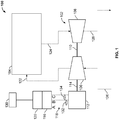
- FIG. 1 is a schematic diagram of an example electronically boosted turbocharger system 100.
- a turbocharger 102 is configured to increase an intake manifold pressure of an internal combustion engine 104.
- the turbocharger 102 includes a compressor 106 configured to take in outside air from an air inlet 126 and to use the air to pressurize the intake manifold 122.
- the turbocharger 102 also includes a turbine 108 that is rotatably coupled to the compressor 106.
- the turbine 108 is configured to convert exhaust flowing through the exhaust header 124 into rotational motion and to rotate the compressor 106 via the turbo shaft 110. After passing through the turbine 108, the exhaust gas flows through the remaining exhaust system 128.
- a three-phase electric motor 112 is rotatably coupled to the turbocharger 102 by a second shaft 114.
- the electric motor 112 is configured to drive and/or be driven by the turbocharger 102.
- the electric motor 112 is configured to accelerate the turbocharger to a pre-set speed, for example, from 50,000 to 170,000 rotations per minute (RPM).
- the electric motor 112 is configured to free-spin once the turbocharger 102 has reached the pre-set speed.
- a VSD 116 is electrically coupled to the electric motor 112.
- the VSD 116 is configured to drive the electric motor 112 with three phases 118 of current.
- the VSD draws power from a power supply 130.
- the power supply 130 can include a vehicular electrical system.
- each phase of current is a sine wave.
- each phase of current is a trapezoidal wave.
- the VSD 116 exchanges current with the electric motor 112 when the electric motor 112 is accelerating.
- a first voltage sensor 132 is configured to measure a first line-to-line terminal voltage, for example, between the A phase and the B phase, of the electric motor 112 while the electric motor 112 free-spins.
- a second voltage sensor 134 is configured to measure a second line-to-line terminal voltage, for example, between the B phase and the C phase of the electric motor 112 while the electric motor 112 free-spins.
- a controller 120 is configured to receive the first voltage and the second voltage from their respective sensors. The controller 120 is configured to determine a rotor position of the electric motor 112 and to send three-phase power to the electric motor 112 via the VSD after the rotor position has been determined.
- the motor's rotor position is defined as the phase angle of the rotor within the stator.
- the variable speed drive is in an inactive state when the rotor position is determined.
- the VSD is not drawing power from the power supply 130 when the rotor position is being determined, but the controller 120 is drawing power from the power supply 130.
- the controller 120 draws less power from the power supply 130 when the controller 120 is in an active state than the VSD 116 when the VSD 116 is in an active state.
- the three-phase power that is sent to the motor, after the position is determined, is in-phase with the electric motor 112 position.
- the VSD is configured to approximate a sine wave with PWM.
- the electric motor 112 is a synchronous permanent magnet electric motor. While described with a synchronous permanent magnet motor, other motor types, such as a brushless DC motor, can be used without departing from this disclosure. As described, the electric motor 112 is directly coupled to the compressor 106. In some implementations, the electric motor can be coupled directly to the turbine 108. In some implementations, a gearbox or other transmission system can be positioned between the electric motor 112 and the turbocharger 102.
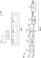
- FIG. 2 is a schematic diagram of an example controller 120 that can be used with aspects of this disclosure.
- the controller 120 includes one or more processors 202 and a non-transitory computer-readable storage medium 204 coupled to the one or more processors 202.
- the non-transitory computer-readable storage medium 204 stores programming instructions for execution by the one or more processors 202.
- the programming instructions are executed by the one or more processors to determine a position based on the first phase voltage and the second phase voltage. Computing a Clarke transform and a Park transform are steps used to determine the position. More details on the specific methods and algorithms to determine motor position are discussed later within this disclosure.
- the controller 120 includes an input/output module 206 that can be used to communicate with one or more aspects of the electronically boosted turbocharger system 100.
- voltage signals from voltage sensors (132, 134) can be fed into the input/output module 206.
- the VSD 116 can be included within the same housing as the controller 120.
- the controller can send and/or receive signals from a VSD 116 that is separate from the controller 120.
- FIG. 3 is a block diagram of an example control loop 300 that can be used with aspects of this disclosure.
- two line-to-line terminal voltages (such as phase A to C and phase B to C) are measured and calibrated with respective gain and offset. After being measured, the voltages are converted to line-neutral voltages ( V b , and V c ). It is assumed that all three phases are balanced.
- Clarke's transformation is used to convert the variables from a three-phase system to a two-phase orthogonal system variables of V ds and V qs according to the following equations.
- Vds 1 / ⁇ 3 Vc ⁇ Vb
- V qs ⁇ V b + V c
- V b is the first phase voltage
- V c is the second phase voltage
- V ds is a first orthogonal component
- V qs is a second orthogonal component
- Park's transformation is used to convert the variables from a two-phase stationary frame to a two-phase rotating frame according to the following equations.
- V qr is a first rotating frame reference voltage
- V dr is second rotating frame reference voltage
- ⁇ is the motor position.
- a filter is applied to the voltage, and a motor speed is determined.
- a phase lock loop (PLL) is used to generate the voltage phase angle (e.g. ⁇ , the motor position) by regulating the voltage V dr to zero.
- the VSD is in an off-state. That is, the VSD is not drawing power from the power supply 130.
- FIG. 4 is a flowchart of an example method 400 that can be used with aspects of this disclosure.
- the method 400 can be implemented by a controller, for example, the controller 120 described with reference to FIG. 1 .
- a first line-to-line terminal voltage of a three-phase electric motor is measured while the three-phase electric motor is allowed to free-spin.
- a second line-to-line terminal voltage of a three-phase electric motor is measured while the three-phase electric motor is allowed to free-spin.
- a motor position is determined based on the first line-to-line terminal voltage and the second line-to-line terminal voltage. Clarke transforms (EQ. 1-2) and Park transforms (EQ. 3-4) are used to determine the motor position.
- three-phase power is sent to the motor after the motor's rotor position has been determined.
- the three-phase power sent to the motor is in-phase with the rotor position.
- sending three-phase power to the motor includes approximating a sine wave with PWM.
- the three-phase power is used to accelerate the motor and turbocharger to a pre-set speed. Once the pre-set speed is reached, the motor is allowed to free-spin.
Landscapes
- Engineering & Computer Science (AREA)
- Chemical & Material Sciences (AREA)
- Combustion & Propulsion (AREA)
- Mechanical Engineering (AREA)
- General Engineering & Computer Science (AREA)
- Power Engineering (AREA)
- Chemical Kinetics & Catalysis (AREA)
- General Chemical & Material Sciences (AREA)
- Supercharger (AREA)
Abstract
Description
- This application claims priority to
U.S. Patent Application No. 16/053,326 filed on August 2, 2018 , the entire contents of which are hereby incorporated by reference. - This disclosure relates to controlling electrical machines, particularly motor generator units (MGUs) used in turbochargers for boosting and energy recovery.
- In automotive and marine systems, turbochargers are used to increase the power output of internal combustion engines. Turbochargers are powered by a turbine within the exhaust manifold of the internal combustion engine. The turbine turns a compressor that increases the pressure and total air flow within the intake manifold. Due to inertia of the rotating components and inefficiencies in the turbine, there is a delay between the pressure supplied to the intake manifold and the pressure needed in the intake manifold due to engine load. Such a delay is often referred to as turbo lag. To counteract turbo lag, some turbochargers include an electrical machine that functions as a booster motor to accelerate the compressor and turbine to a desired speed quicker than the turbo would accelerate on its own. Besides boosting, the electrical machine can also functions as a generator to recover excess exhaust energy from the engine.
- This disclosure describes technologies relating to controlling an electronically-assisted turbocharger.
- An example implementation of the subject matter described within this disclosure is a method of controlling an electrically assisted turbocharger with the following features. A first line-to-line terminal voltage of a three-phase electric motor is measured while the three-phase electric motor free-spins. A second line-to-line terminal voltage of a three-phase electric motor is measured while the three-phase electric motor free-spins. A motor's rotor position is determined based on the first line-to-line terminal voltage and the second line-to-line terminal voltage. Three-phase current is sent to the motor after the rotor position has been determined. The three-phase current being in-phase with the rotor position.
- Aspects of the example implementation, which can be combined with the example implementation alone or in combination, include the following. The motor is a permanent magnet synchronous motor.
- Aspects of the example implementation, which can be combined with the example implementation alone or in combination, include the following. Sending three-phase current to the motor comprises approximating a sine wave with pulse width modulation.
- Aspects of the example implementation, which can be combined with the example implementation alone or in combination, include the following. The motor is accelerated to a pre-set speed.
- Aspects of the example implementation, which can be combined with the example implementation alone or in combination, include the following. The motor is coupled to or integrated in a turbocharger. The turbocharger is accelerated to the pre-set speed.
- Aspects of the example implementation, which can be combined with the example implementation alone or in combination, include the following. The motor is allowed to free-spin once the pre-set speed is reached.
- Aspects of the example implementation, which can be combined with the example implementation alone or in combination, include the following. Determining the motor position includes using the following equations:


- Aspects of the example implementation, which can be combined with the example implementation alone or in combination, include the following. Determining the motor's rotor position includes using the following equations:


- Aspects of the example implementation, which can be combined with the example implementation alone or in combination, include the following. Determining the rotor position includes using a phase lock loop to generate a voltage phase angle.
- Aspects of the example implementation, which can be combined with the example implementation alone or in combination, include the following. Using the phase lock loop includes regulating Vdr to zero volts.
- An example implementation of the subject matter described within this disclosure is an electric motor control system with the following features. A three-phase electric machine is configured to drive or be driven by a rotating device. A variable speed drive is electrically coupled to the electrical machine. The variable speed drive is configured to drive the electric machine with three phases of current. A first voltage sensor is configured to measure a first line-to-line terminal voltage of the three-phase electric machine while the three-phase electric machine free-spins. A second voltage sensor is configured to measure a second line-to-line terminal voltage of the three-phase electric machine while the three-phase electric machine free-spins. A controller is configured to receive the first line-to-line terminal voltage and the second line-to-line terminal voltage. The controller is configured to determine the rotor position of the three-phase electric machine. The controller is configured to send three-phase power to the three-phase electric machine after the three-phase electric machine's rotor position has been determined. The three phase power being in-phase with the three-phase electric machine's rotor position.
- Aspects of the example implementation, which can be combined with the example implementation alone or in combination, include the following. The rotating device includes a turbocharger.
- Aspects of the example implementation, which can be combined with the example implementation alone or in combination, include the following. The controller includes one or more processors and a non-transitory computer-readable storage medium coupled to the one or more processors that stores programming instructions for execution by the one or more processors. The programming instructions executable by the one or more processors includes determining the position based on the first line-to-line terminal voltage and the second line-to-line terminal voltage.
- Aspects of the example implementation, which can be combined with the example implementation alone or in combination, include the following. The programming instructions executable by the one or more processors to determine the position include instructions executable by the one or more processors to compute a Clarke transform and a Park transform.
- Aspects of the example implementation, which can be combined with the example implementation alone or in combination, include the following. The electric machine is a synchronous permanent magnet electric machine.
- An example implementation of the subject matter described with this disclosure is an electrically boosted turbocharger system with the following features. A turbocharger is configured to increase an intake manifold pressure of an internal combustion engine. The turbocharger includes a compressor configured to increase the intake manifold pressure, and a turbine rotatably coupled to the compressor. The turbine is configured to convert exhaust flow into rotational motion. The turbine is configured to rotate the compressor. A three-phase electric motor is rotatably coupled to the turbocharger. The motor is configured to accelerate the turbocharger to a pre-set speed. A variable speed drive is electrically coupled to the motor. The variable speed drive is configured to drive the electric motor with three phases of current. The variable speed drive is configured to exchange current with the electric motor when the electric motor is accelerating. A first voltage sensor is configured to measure a first line-to-line terminal voltage of the three-phase electric motor while the three-phase electric motor free-spins. A second voltage sensor is configured to measure a second line-to-line terminal voltage of the three-phase electric motor while the three-phase electric motor free-spins.
- Aspects of the example implementation, which can be combined with the example implementation alone or in combination, include the following. The electric motor is directly coupled to the compressor.
- Aspects of the example implementation, which can be combined with the example implementation alone or in combination, include the following. The electric motor is a synchronous permanent magnet motor.
- Aspects of the example implementation, which can be combined with the example implementation alone or in combination, include the following. The variable speed drive is configured to approximate a sine wave with pulse width modulation.
- Aspects of the example implementation, which can be combined with the example implementation alone or in combination, include the following. The electrically boosted turbocharger system includes a controller with one or more processors and a non-transitory computer-readable storage medium coupled to the one or more processors that stores programming instructions for execution by the one or more processors. The programming instructions executable by the one or more processors include instructions to determine a motor position based on the first line-to-line terminal voltage or the second line-to-line terminal voltage.
- Aspects of the example implementation, which can be combined with the example implementation alone or in combination, include the following. The programming instructions to instruct the one or more processors to determine a motor's rotor position include computing a Clarke transform or a Park transform.
- Aspects of the example implementation, which can be combined with the example implementation alone or in combination, include the following. The variable speed drive is in an inactive state when the motor's rotor position is determined.
- Aspects of the example implementation, which can be combined with the example implementation alone or in combination, include the following. The electric motor is configured to free-spin once the turbocharger has reached the pre-set speed.
- The details of one or more implementations of the subject matter described in this disclosure are set forth in the accompanying drawings and the description below. Other features, aspects, and advantages of the subject matter will become apparent from the description, the drawings, and the claims.
-
-
FIG. 1 is a schematic diagram of an example electronically boosted turbocharger system. -
FIG. 2 is a schematic diagram of an example controller that can be used with aspects of this disclosure. -
FIG. 3 is a block diagram of an example control-loop that can be used with aspects of this disclosure. -
FIG. 4 is a flowchart of an example method that can be used with aspects of this disclosure. - Like reference numbers and designations in the various drawings indicate like elements.
- Electronically boosted turbochargers require a significant amount of power to accelerate the turbocharger, for example, up to ten kilowatts for a typical passenger automobile application. When a variable speed drive (VSD) and motor are used to electronically boost the turbocharger, the variable speed drive is often active and powered even after the turbocharger is up to speed. Keeping the VSD powered is useful during variable load situations, such as high traffic situations, where the turbocharger will be frequently accelerating and decelerating. VSD power consumption can be as high as several hundred watts during idling condition when pulse width modulations (PWM) is required to keep switching at high switching frequency in order to know the real time rotor position information. Since the VSD is in idling condition frequently, such a power consumption reduces the overall system efficiency. In addition, keeping VSD active will also induce additional losses in the motor. While keeping the VSD active draws significant power from the electrical system, it can be necessary in some systems to constantly determine the rotor position of the motor. Such information is necessary for the function of a VSD. In particular, the current from VSD needs to be in phase with the rotor position of the motor. If the phasing between the VSD and the motor is off, then inefficiencies, overheating, and other undesirable results can occur.
- This disclosure relates to an electronically boosted turbocharger system that senses a rotor position of the motor without keeping the VSD active, saving significant electrical energy. The system works by allowing the motor to free spin. That is, the VSD is in an off-state. In instances where a three-phase motor is used as the electronic booster, two voltage sensors are coupled to measure two line-to-line voltages of the three motor phases. A controller determines a rotor position during freewheeling using a Clarke transform and/or a Park transform. The VSD is activated only when the motor is accelerating the turbocharger. In some implementations, the VSD is configured to approximate a sine wave with PWM switching circuitry. By using the subject matter disclosed herein, an electronic booster can have a fast response to the speed demand while still maintaining high efficiency by keeping the VSD PWM switching off when the assistance is not needed.
-
FIG. 1 is a schematic diagram of an example electronically boostedturbocharger system 100. Aturbocharger 102 is configured to increase an intake manifold pressure of aninternal combustion engine 104. Theturbocharger 102 includes acompressor 106 configured to take in outside air from anair inlet 126 and to use the air to pressurize theintake manifold 122. Theturbocharger 102 also includes aturbine 108 that is rotatably coupled to thecompressor 106. Theturbine 108 is configured to convert exhaust flowing through theexhaust header 124 into rotational motion and to rotate thecompressor 106 via theturbo shaft 110. After passing through theturbine 108, the exhaust gas flows through the remainingexhaust system 128. - A three-phase
electric motor 112 is rotatably coupled to theturbocharger 102 by asecond shaft 114. Theelectric motor 112 is configured to drive and/or be driven by theturbocharger 102. Theelectric motor 112 is configured to accelerate the turbocharger to a pre-set speed, for example, from 50,000 to 170,000 rotations per minute (RPM). Theelectric motor 112 is configured to free-spin once theturbocharger 102 has reached the pre-set speed. - A
VSD 116 is electrically coupled to theelectric motor 112. TheVSD 116 is configured to drive theelectric motor 112 with threephases 118 of current. The VSD draws power from apower supply 130. Thepower supply 130 can include a vehicular electrical system. In some implementations, each phase of current is a sine wave. In some implementations, each phase of current is a trapezoidal wave. TheVSD 116 exchanges current with theelectric motor 112 when theelectric motor 112 is accelerating. Afirst voltage sensor 132 is configured to measure a first line-to-line terminal voltage, for example, between the A phase and the B phase, of theelectric motor 112 while theelectric motor 112 free-spins. Asecond voltage sensor 134 is configured to measure a second line-to-line terminal voltage, for example, between the B phase and the C phase of theelectric motor 112 while theelectric motor 112 free-spins. Acontroller 120 is configured to receive the first voltage and the second voltage from their respective sensors. Thecontroller 120 is configured to determine a rotor position of theelectric motor 112 and to send three-phase power to theelectric motor 112 via the VSD after the rotor position has been determined. In the context of this disclosure, the motor's rotor position is defined as the phase angle of the rotor within the stator. The variable speed drive is in an inactive state when the rotor position is determined. That is, the VSD is not drawing power from thepower supply 130 when the rotor position is being determined, but thecontroller 120 is drawing power from thepower supply 130. Thecontroller 120 draws less power from thepower supply 130 when thecontroller 120 is in an active state than theVSD 116 when theVSD 116 is in an active state. The three-phase power that is sent to the motor, after the position is determined, is in-phase with theelectric motor 112 position. In some implementations, the VSD is configured to approximate a sine wave with PWM. - While described as driving a
turbocharger 102, the motor control system described within this disclosure can be applied to other applications. In some implementations, theelectric motor 112 is a synchronous permanent magnet electric motor. While described with a synchronous permanent magnet motor, other motor types, such as a brushless DC motor, can be used without departing from this disclosure. As described, theelectric motor 112 is directly coupled to thecompressor 106. In some implementations, the electric motor can be coupled directly to theturbine 108. In some implementations, a gearbox or other transmission system can be positioned between theelectric motor 112 and theturbocharger 102. -
FIG. 2 is a schematic diagram of anexample controller 120 that can be used with aspects of this disclosure. Thecontroller 120 includes one ormore processors 202 and a non-transitory computer-readable storage medium 204 coupled to the one ormore processors 202. The non-transitory computer-readable storage medium 204 stores programming instructions for execution by the one ormore processors 202. The programming instructions are executed by the one or more processors to determine a position based on the first phase voltage and the second phase voltage. Computing a Clarke transform and a Park transform are steps used to determine the position. More details on the specific methods and algorithms to determine motor position are discussed later within this disclosure. Thecontroller 120 includes an input/output module 206 that can be used to communicate with one or more aspects of the electronically boostedturbocharger system 100. For example, voltage signals from voltage sensors (132, 134) can be fed into the input/output module 206. In some implementations, theVSD 116 can be included within the same housing as thecontroller 120. In some implementations, the controller can send and/or receive signals from aVSD 116 that is separate from thecontroller 120. -
FIG. 3 is a block diagram of anexample control loop 300 that can be used with aspects of this disclosure. Atblock 302, two line-to-line terminal voltages (such as phase A to C and phase B to C) are measured and calibrated with respective gain and offset. After being measured, the voltages are converted to line-neutral voltages (Vb , and Vc ). It is assumed that all three phases are balanced. Atblock 304, Clarke's transformation is used to convert the variables from a three-phase system to a two-phase orthogonal system variables of Vds and Vqs according to the following equations.

- At
block 306, Park's transformation is used to convert the variables from a two-phase stationary frame to a two-phase rotating frame according to the following equations.

block 308, a filter is applied to the voltage, and a motor speed is determined. Atblock 310, a phase lock loop (PLL) is used to generate the voltage phase angle (e.g. θ, the motor position) by regulating the voltage Vdr to zero. During this process, the VSD is in an off-state. That is, the VSD is not drawing power from thepower supply 130. -
FIG. 4 is a flowchart of anexample method 400 that can be used with aspects of this disclosure. In some implementations, themethod 400 can be implemented by a controller, for example, thecontroller 120 described with reference toFIG. 1 . At 402, a first line-to-line terminal voltage of a three-phase electric motor is measured while the three-phase electric motor is allowed to free-spin. At 404, a second line-to-line terminal voltage of a three-phase electric motor is measured while the three-phase electric motor is allowed to free-spin. At 406, a motor position is determined based on the first line-to-line terminal voltage and the second line-to-line terminal voltage. Clarke transforms (EQ. 1-2) and Park transforms (EQ. 3-4) are used to determine the motor position. At 408, three-phase power is sent to the motor after the motor's rotor position has been determined. The three-phase power sent to the motor is in-phase with the rotor position. In some implementations, sending three-phase power to the motor includes approximating a sine wave with PWM. The three-phase power is used to accelerate the motor and turbocharger to a pre-set speed. Once the pre-set speed is reached, the motor is allowed to free-spin. - While this disclosure contains many specific implementation details, these should not be construed as limitations on the scope of what may be claimed, but rather as descriptions of features specific to particular implementations. Certain features that are described in this disclosure in the context of separate implementations can also be implemented in combination in a single embodiment. Conversely, various features that are described in the context of a single embodiment can also be implemented in multiple implementations separately or in any suitable subcombination. Moreover, although features may be described above as acting in certain combinations and even initially claimed as such, one or more features from a claimed combination can in some cases be excised from the combination, and the claimed combination may be directed to a subcombination or variation of a subcombination.
- Similarly, while operations are depicted in the drawings in a particular order, this should not be understood as requiring that such operations be performed in the particular order shown or in sequential order, or that all illustrated operations be performed, to achieve desirable results. Moreover, the separation of various system components in the implementations described above should not be understood as requiring such separation in all implementations, and it should be understood that the described components and systems can generally be integrated together in a single product or packaged into multiple products. For example, the
electric motor 112 can be integrated into the turbocharger as a single unit. - Thus, particular implementations of the subject matter have been described. Other implementations are within the scope of the following claims. In some cases, the actions recited in the claims can be performed in a different order and still achieve desirable results. In addition, the processes depicted in the accompanying figures do not necessarily require the particular order shown, or sequential order, to achieve desirable results.
- Although the present invention is defined in the attached claims, it should be understood that the present invention can also (alternatively) be defined in accordance with the following embodiments:
- 1. A method of controlling an electrically assisted turbocharger:
- measuring a first line-to-line terminal voltage of a three-phase electric motor while the three-phase electric motor free-spins;
- measuring a second line-to-line terminal voltage of a three-phase electric motor while the three-phase electric motor free-spins;
- determining a motor's rotor position based on the first line-to-line terminal voltage and the second line-to-line terminal voltage; and
- sending a three-phase current to the motor after the rotor position has been determined, the three-phase current being in-phase with the motor's rotor position.
- 2. The method of
embodiment 1, wherein the motor is a permanent magnet synchronous motor. - 3. The method of
embodiment 1, wherein sending three-phase current to the motor comprises approximating a sine wave with pulse width modulation. - 4. The method of
embodiment 1, further comprising accelerating the motor to a pre-set speed. - 5. The method of embodiment 4, wherein the motor is coupled to or integrated in a turbocharger, the method further comprising accelerating the turbocharger to the pre-set speed.
- 6. The method of embodiment 5, further comprising allowing the motor to free-spin once the pre-set speed is reached.
- 7. The method of
embodiment 1, wherein determining the motor's rotor position comprises using the following equations:

- 8. The method of embodiment 7, wherein determining the motor's rotor position comprises using the following equations:


- 9. The method of embodiment 8, wherein determining the motor's rotor position comprises using a phase lock loop to generate a voltage phase angle.
- 10. The method of embodiment 9, wherein using the phase lock loop comprises regulating Vdr to zero volts.
- 11. An electric motor control system comprising;
a three-phase electric machine configured to drive or be driven by a rotating device;
a variable speed drive electrically coupled to the electrical machine, the variable speed drive configured to drive the electric machine with three phases of current;
a first voltage sensor configured to measure a first line-to-line terminal voltage of the three-phase electric machine while the three-phase electric machine free-spins;
a second voltage sensor configured to measure a second line-to-line terminal voltage of the three-phase electric machine while the three-phase electric machine free-spins; and
a controller configured to:- receive the first line-to-line terminal voltage and the second line-to-line terminal voltage,
- determine rotor position of the three-phase electric machine, and
- send three-phase power to the three-phase electric machine after the three-phase electric machine's rotor position has been determined, the three phase power being in-phase with the three-phase electric machine's rotor position.
- 12. The electric motor control system of embodiment 11, wherein the rotating device comprises a turbocharger.
- 13. The electric motor control system of embodiment 11, wherein the controller comprises:
- one or more processors; and
- a non-transitory computer-readable storage medium coupled to the one or more processors and storing programming instructions for execution by the one or more processors, the programming instructions executable by the one or more processors to:
determine the position based on the first line-to-line terminal voltage and the second line-to-line terminal voltage.
- 14. The electric motor control system of embodiment 13, wherein the programming instructions executable by the one or more processors to determine the position include instructions executable by the one or more processors to compute a Clarke transform and a Park transform.
- 15. The electric motor control system of embodiment 11, wherein the electric machine is a synchronous permanent magnet electric machine.
- 16. An electrically boosted turbocharger system comprising:
- a turbocharger configured to increase an intake manifold pressure of an internal combustion engine, the turbocharger comprising:
- a compressor configure to increase the intake manifold pressure; and
- a turbine rotatably coupled to the compressor, the turbine configured to convert exhaust flow into rotational motion, the turbine configured to rotate the compressor;
- a three-phase electric motor rotatably coupled to the turbocharger, the motor configured to accelerate the turbocharger to a pre-set speed;
- a variable speed drive electrically coupled to the motor, the variable speed drive configured to drive the electric motor with three phases of current, the variable speed drive configured to exchange current with the electric motor when the electric motor is accelerating;
- a first voltage sensor configured to measure a first line-to-line terminal voltage of the three-phase electric motor while the three-phase electric motor free-spins; and
- a second voltage sensor configured to measure a second line-to-line terminal voltage of the three-phase electric motor while the three-phase electric motor free-spins.
- a turbocharger configured to increase an intake manifold pressure of an internal combustion engine, the turbocharger comprising:
- 17. The electrically boosted turbocharger system of embodiment 16, wherein the electric motor is directly coupled to the compressor.
- 18. The electrically boosted turbocharger system of embodiment 16, wherein the electric motor is a synchronous permanent magnet motor.
- 19. The electrically boosted turbocharger system embodiment 16, wherein the variable speed drive is configured to approximate a sine wave with pulse width modulation.
- 20. The electrically boosted turbocharger system of embodiment 16, further comprising a controller comprising:
- one or more processors; and
- a non-transitory computer-readable storage medium coupled to the one or more processors and storing programming instructions for execution by the one or more processors, the programming instructions executable by the one or more processors to:
determine a motor's rotor position based on the first line-to-line terminal voltage or the second line-to-line terminal voltage.
- 21. The electrically boosted turbocharger system of embodiment 20, wherein the programming instructions to instruct the one or more processors to determine a motor's rotor position include computing a Clarke transform or a Park transform.
- 22. The electrically boosted turbocharger system of embodiment 21, wherein the variable speed drive is in an inactive state when the motor's rotor position is determined.
- 23. The electrically boosted turbocharger system of embodiment 16, wherein the electric motor is configured to free-spin once the turbocharger has reached the pre-set speed.
Claims (16)
- A method of controlling an electrically assisted turbocharger, the method comprising:measuring a first line-to-line terminal voltage of a three-phase electric motor while the three-phase electric motor free-spins;measuring a second line-to-line terminal voltage of a three-phase electric motor while the three-phase electric motor free-spins;determining a motor's rotor position based on the first line-to-line terminal voltage and the second line-to-line terminal voltage; andsending a three-phase current to the motor after the rotor position has been determined, the three-phase current being in-phase with the motor's rotor position.
- The method of claim 1, wherein the motor is a permanent magnet synchronous motor.
- The method of claim 1, wherein sending three-phase current to the motor comprises approximating a sine wave with pulse width modulation.
- The method of claim 1, further comprising accelerating the motor to a pre-set speed.
- The method of claim 4, wherein the motor is coupled to or integrated in a turbocharger, the method further comprising accelerating the turbocharger to the pre-set speed, and
optionally wherein the method further comprises allowing the motor to free-spin once the pre-set speed is reached. - The method of claim 1, wherein determining the motor's rotor position comprises using the following equations:


- The method of claim 6, wherein determining the motor's rotor position comprises using the following equations:

 wherein Vqr is a first rotating frame reference voltage, Vdr is second rotating frame reference voltage, and θ is the rotor position, andoptionally wherein determining the motor's rotor position comprises using a phase lock loop to generate a voltage phase angle, for example, wherein using the phase lock loop comprises regulating Vdr to zero volts.
 - An electric motor control system comprising;
a three-phase electric machine configured to drive or be driven by a rotating device;
a variable speed drive electrically coupled to the electrical machine, the variable speed drive configured to drive the electric machine with three phases of current;
a first voltage sensor configured to measure a first line-to-line terminal voltage of the three-phase electric machine while the three-phase electric machine free-spins;
a second voltage sensor configured to measure a second line-to-line terminal voltage of the three-phase clcctric machine while the three-phase electric machine free-spins; and
a controller configured to:receive the first line-to-line terminal voltage and the second line-to-line terminal voltage,determine rotor position of the three-phase electric machine, andsend three-phase power to the three-phase electric machine after the three-phase electric machine's rotor position has been determined, the three phase power being in-phase with the three-phase electric machine's rotor position. - The electric motor control system of claim 8, wherein the rotating device comprises a turbocharger.
- The electric motor control system of claim 8, wherein the controller comprises:one or more processors; anda non-transitory computer-readable storage medium coupled to the one or more processors and storing programming instructions for execution by the one or more processors, the programming instructions executable by the one or more processors to:
determine the position based on the first line-to-line terminal voltage and the second line-to-line terminal voltage. - The electric motor control system of claim 10, wherein the programming instructions executable by the one or more processors to determine the position include instructions executable by the one or more processors to compute a Clarke transform or a Park transform, and
optionally wherein the variable speed drive is in an inactive state when the motor's rotor position is determined. - The electric motor control system of claim 8, wherein the electric machine is a synchronous permanent magnet electric machine.
- An electrically boosted turbocharger system comprising:a turbocharger configured to increase an intake manifold pressure of an internal combustion engine, the turbocharger comprising:a compressor configure to increase the intake manifold pressure; anda turbine rotatably coupled to the compressor, the turbine configured to convert exhaust flow into rotational motion, the turbine configured to rotate the compressor; andthe electric motor control system of any one of claims 8 to 12, wherein:the three-phase electric machine is a three-phase electric motor rotatably coupled to the turbocharger, the motor configured to accelerate the turbocharger to a pre-set speed, andthe variable speed drive is configured to exchange current with the electric motor when the electric motor is accelerating .
- The electrically boosted turbocharger system of claim 13, wherein the electric motor is directly coupled to the compressor.
- The electrically boosted turbocharger system claim 13, wherein the variable speed drive is configured to approximate a sine wave with pulse width modulation.
- The electrically boosted turbocharger system of claim 13, wherein the electric motor is configured to free-spin once the turbocharger has reached the pre-set speed.
Applications Claiming Priority (1)
| Application Number | Priority Date | Filing Date | Title |
|---|---|---|---|
| US16/053,326 US10753270B2 (en) | 2018-08-02 | 2018-08-02 | Controlling an electronically-assisted turbocharger |
Publications (1)
| Publication Number | Publication Date |
|---|---|
| EP3605831A1 true EP3605831A1 (en) | 2020-02-05 |
Family
ID=67514430
Family Applications (1)
| Application Number | Title | Priority Date | Filing Date |
|---|---|---|---|
| EP19189445.0A Withdrawn EP3605831A1 (en) | 2018-08-02 | 2019-07-31 | Controlling an electronically-assisted turbocharger |
Country Status (2)
| Country | Link |
|---|---|
| US (1) | US10753270B2 (en) |
| EP (1) | EP3605831A1 (en) |
Families Citing this family (1)
| Publication number | Priority date | Publication date | Assignee | Title |
|---|---|---|---|---|
| US12480423B2 (en) * | 2020-12-18 | 2025-11-25 | General Electric Company | System and method for mitigating bowed rotor in a gas turbine engine |
Citations (2)
| Publication number | Priority date | Publication date | Assignee | Title |
|---|---|---|---|---|
| JP2007116768A (en) * | 2005-10-18 | 2007-05-10 | Ishikawajima Harima Heavy Ind Co Ltd | Rotation detector for turbocharger with electric motor |
| CN105915141A (en) * | 2016-05-09 | 2016-08-31 | 中国第汽车股份有限公司 | Permanent magnet synchronous motor permanent magnet linkage online measurement system and method |
Family Cites Families (1)
| Publication number | Priority date | Publication date | Assignee | Title |
|---|---|---|---|---|
| JP6635011B2 (en) * | 2016-12-13 | 2020-01-22 | 株式会社豊田自動織機 | Internal combustion engine control system |
-
2018
- 2018-08-02 US US16/053,326 patent/US10753270B2/en active Active
-
2019
- 2019-07-31 EP EP19189445.0A patent/EP3605831A1/en not_active Withdrawn
Patent Citations (2)
| Publication number | Priority date | Publication date | Assignee | Title |
|---|---|---|---|---|
| JP2007116768A (en) * | 2005-10-18 | 2007-05-10 | Ishikawajima Harima Heavy Ind Co Ltd | Rotation detector for turbocharger with electric motor |
| CN105915141A (en) * | 2016-05-09 | 2016-08-31 | 中国第汽车股份有限公司 | Permanent magnet synchronous motor permanent magnet linkage online measurement system and method |
Non-Patent Citations (1)
| Title |
|---|
| BRADSHAW J ET AL: "Bit-stream implementation of a phase-locked loop", THE INSTITUTION OF ENGINEERING AND TECHNOLOGY. JOURNAL,, vol. 4, no. 1, 4 January 2011 (2011-01-04), pages 11 - 20, XP006037470, ISSN: 1755-4543, DOI: 10.1049/IET-PEL:20100009 * |
Also Published As
| Publication number | Publication date |
|---|---|
| US20200040811A1 (en) | 2020-02-06 |
| US10753270B2 (en) | 2020-08-25 |
Similar Documents
| Publication | Publication Date | Title |
|---|---|---|
| Lee et al. | Torque ripple minimization control technique of high-speed single-phase brushless DC motor for electric turbocharger | |
| EP2696496B1 (en) | Motor control device | |
| US8193747B2 (en) | Methods, systems and apparatus for controlling operation of two alternating current (AC) machines | |
| US9602040B2 (en) | Apparatus for controlling first and second rotary electric machines | |
| US6515446B1 (en) | Motor control apparatus and control method | |
| US20030011340A1 (en) | Motor apparatus and control method therefor | |
| US7847501B2 (en) | Varying flux versus torque for maximum efficiency | |
| JP2021061746A (en) | Motor driving device and control method of motor driving device | |
| CN103780191A (en) | Open winding permanent magnet synchronous motor series compensation vector control system and control method | |
| TW201830846A (en) | System and method for starting a synchronous motor | |
| CN108390602B (en) | A Direct Predictive Power Control Method for Hybrid Excitation Synchronous Motors | |
| US7538510B2 (en) | Controller for motor | |
| EP1774646B1 (en) | Apparatus and method to control torque and voltage of an ac machine | |
| US10033252B2 (en) | Sensorless control of a DC synchronous machine | |
| EP3565102A1 (en) | Inverter driving device and electric vehicle system in which same is used | |
| US10608566B2 (en) | Control apparatus for rotary electric machines | |
| JP2016111761A (en) | Rotary electric machine control device | |
| JP4357826B2 (en) | Electric motor operation control device | |
| EP3605831A1 (en) | Controlling an electronically-assisted turbocharger | |
| CN109194228A (en) | A kind of starting of salient pole type synchronous motor position-sensor-free and method for control speed | |
| US7375482B2 (en) | Driving device of motor | |
| EP3015677B1 (en) | Control apparatus for internal combustion engine | |
| JP5131051B2 (en) | Rotating machine control device and rotating machine control system | |
| CN102342018A (en) | motor control device | |
| JP2000205002A (en) | Control device and control method for hybrid vehicle drive device |
Legal Events
| Date | Code | Title | Description |
|---|---|---|---|
| PUAI | Public reference made under article 153(3) epc to a published international application that has entered the european phase |
Free format text: ORIGINAL CODE: 0009012 |
|
| STAA | Information on the status of an ep patent application or granted ep patent |
Free format text: STATUS: REQUEST FOR EXAMINATION WAS MADE |
|
| 17P | Request for examination filed |
Effective date: 20190731 |
|
| AK | Designated contracting states |
Kind code of ref document: A1 Designated state(s): AL AT BE BG CH CY CZ DE DK EE ES FI FR GB GR HR HU IE IS IT LI LT LU LV MC MK MT NL NO PL PT RO RS SE SI SK SM TR |
|
| AX | Request for extension of the european patent |
Extension state: BA ME |
|
| STAA | Information on the status of an ep patent application or granted ep patent |
Free format text: STATUS: EXAMINATION IS IN PROGRESS |
|
| 17Q | First examination report despatched |
Effective date: 20201221 |
|
| STAA | Information on the status of an ep patent application or granted ep patent |
Free format text: STATUS: THE APPLICATION IS DEEMED TO BE WITHDRAWN |
|
| 18D | Application deemed to be withdrawn |
Effective date: 20210701 |