EP3605828A1 - Motor control device, motor control method, and motor control system - Google Patents
Motor control device, motor control method, and motor control system Download PDFInfo
- Publication number
- EP3605828A1 EP3605828A1 EP17903987.0A EP17903987A EP3605828A1 EP 3605828 A1 EP3605828 A1 EP 3605828A1 EP 17903987 A EP17903987 A EP 17903987A EP 3605828 A1 EP3605828 A1 EP 3605828A1
- Authority
- EP
- European Patent Office
- Prior art keywords
- motor control
- motor
- identification information
- control apparatus
- sensor
- Prior art date
- Legal status (The legal status is an assumption and is not a legal conclusion. Google has not performed a legal analysis and makes no representation as to the accuracy of the status listed.)
- Granted
Links
Images



Classifications
-
- H—ELECTRICITY
- H02—GENERATION; CONVERSION OR DISTRIBUTION OF ELECTRIC POWER
- H02P—CONTROL OR REGULATION OF ELECTRIC MOTORS, ELECTRIC GENERATORS OR DYNAMO-ELECTRIC CONVERTERS; CONTROLLING TRANSFORMERS, REACTORS OR CHOKE COILS
- H02P29/00—Arrangements for regulating or controlling electric motors, appropriate for both AC and DC motors
- H02P29/02—Providing protection against overload without automatic interruption of supply
- H02P29/024—Detecting a fault condition, e.g. short circuit, locked rotor, open circuit or loss of load
-
- H—ELECTRICITY
- H02—GENERATION; CONVERSION OR DISTRIBUTION OF ELECTRIC POWER
- H02P—CONTROL OR REGULATION OF ELECTRIC MOTORS, ELECTRIC GENERATORS OR DYNAMO-ELECTRIC CONVERTERS; CONTROLLING TRANSFORMERS, REACTORS OR CHOKE COILS
- H02P23/00—Arrangements or methods for the control of AC motors characterised by a control method other than vector control
- H02P23/0077—Characterised by the use of a particular software algorithm
-
- B—PERFORMING OPERATIONS; TRANSPORTING
- B25—HAND TOOLS; PORTABLE POWER-DRIVEN TOOLS; MANIPULATORS
- B25J—MANIPULATORS; CHAMBERS PROVIDED WITH MANIPULATION DEVICES
- B25J9/00—Program-controlled manipulators
- B25J9/16—Program controls
- B25J9/1602—Program controls characterised by the control system, structure, architecture
- B25J9/161—Hardware, e.g. neural networks, fuzzy logic, interfaces, processor
-
- G—PHYSICS
- G05—CONTROLLING; REGULATING
- G05B—CONTROL OR REGULATING SYSTEMS IN GENERAL; FUNCTIONAL ELEMENTS OF SUCH SYSTEMS; MONITORING OR TESTING ARRANGEMENTS FOR SUCH SYSTEMS OR ELEMENTS
- G05B19/00—Program-control systems
- G05B19/02—Program-control systems electric
- G05B19/04—Program control other than numerical control, i.e. in sequence controllers or logic controllers
- G05B19/048—Monitoring; Safety
-
- H—ELECTRICITY
- H02—GENERATION; CONVERSION OR DISTRIBUTION OF ELECTRIC POWER
- H02P—CONTROL OR REGULATION OF ELECTRIC MOTORS, ELECTRIC GENERATORS OR DYNAMO-ELECTRIC CONVERTERS; CONTROLLING TRANSFORMERS, REACTORS OR CHOKE COILS
- H02P5/00—Arrangements specially adapted for regulating or controlling the speed or torque of two or more electric motors
- H02P5/46—Arrangements specially adapted for regulating or controlling the speed or torque of two or more electric motors for speed regulation of two or more dynamo-electric motors in relation to one another
-
- H—ELECTRICITY
- H02—GENERATION; CONVERSION OR DISTRIBUTION OF ELECTRIC POWER
- H02P—CONTROL OR REGULATION OF ELECTRIC MOTORS, ELECTRIC GENERATORS OR DYNAMO-ELECTRIC CONVERTERS; CONTROLLING TRANSFORMERS, REACTORS OR CHOKE COILS
- H02P6/00—Arrangements for controlling synchronous motors or other dynamo-electric motors using electronic commutation dependent on the rotor position; Electronic commutators therefor
- H02P6/04—Arrangements for controlling or regulating the speed or torque of more than one motor
-
- G—PHYSICS
- G05—CONTROLLING; REGULATING
- G05B—CONTROL OR REGULATING SYSTEMS IN GENERAL; FUNCTIONAL ELEMENTS OF SUCH SYSTEMS; MONITORING OR TESTING ARRANGEMENTS FOR SUCH SYSTEMS OR ELEMENTS
- G05B19/00—Program-control systems
- G05B19/02—Program-control systems electric
- G05B19/18—Numerical control [NC], i.e. automatically operating machines, in particular machine tools, e.g. in a manufacturing environment, so as to execute positioning, movement or co-ordinated operations by means of program data in numerical form
- G05B19/414—Structure of the control system, e.g. common controller or multiprocessor systems, interface to servo, programmable interface controller
-
- G—PHYSICS
- G05—CONTROLLING; REGULATING
- G05B—CONTROL OR REGULATING SYSTEMS IN GENERAL; FUNCTIONAL ELEMENTS OF SUCH SYSTEMS; MONITORING OR TESTING ARRANGEMENTS FOR SUCH SYSTEMS OR ELEMENTS
- G05B2219/00—Program-control systems
- G05B2219/20—Pc systems
- G05B2219/24—Pc safety
- G05B2219/24015—Monitoring
-
- G—PHYSICS
- G05—CONTROLLING; REGULATING
- G05B—CONTROL OR REGULATING SYSTEMS IN GENERAL; FUNCTIONAL ELEMENTS OF SUCH SYSTEMS; MONITORING OR TESTING ARRANGEMENTS FOR SUCH SYSTEMS OR ELEMENTS
- G05B2219/00—Program-control systems
- G05B2219/30—Nc systems
- G05B2219/33—Director till display
- G05B2219/33123—Identify kind of transducer, encoder used
-
- G—PHYSICS
- G05—CONTROLLING; REGULATING
- G05B—CONTROL OR REGULATING SYSTEMS IN GENERAL; FUNCTIONAL ELEMENTS OF SUCH SYSTEMS; MONITORING OR TESTING ARRANGEMENTS FOR SUCH SYSTEMS OR ELEMENTS
- G05B2219/00—Program-control systems
- G05B2219/30—Nc systems
- G05B2219/33—Director till display
- G05B2219/33226—Daisy chain
-
- G—PHYSICS
- G05—CONTROLLING; REGULATING
- G05B—CONTROL OR REGULATING SYSTEMS IN GENERAL; FUNCTIONAL ELEMENTS OF SUCH SYSTEMS; MONITORING OR TESTING ARRANGEMENTS FOR SUCH SYSTEMS OR ELEMENTS
- G05B2219/00—Program-control systems
- G05B2219/30—Nc systems
- G05B2219/40—Robotics, robotics mapping to robotics vision
- G05B2219/40237—Bus for communication with sensors
Definitions
- the present disclosure relates to a motor control apparatus, a motor control method, and a motor control system.
- Patent Literature 1 discloses a system in which a plurality of sensors are connected to an interface unit through respective communication paths, and a detection signal of each of the sensors is transmitted to a host controller or a motor control apparatus via a network that connects the host controller and the motor control apparatus to each other.
- Patent Literature 2 discloses a system in which a peripheral device that sets a parameter of a motor control apparatus or performs monitoring of the motor control apparatus through a communication unit in the motor control apparatus is connected.
- each sensor or each peripheral device is connected to a motor control apparatus, and thus a physical or processing cost tends to increase, in the system in the related art.
- the present disclosure has been made in consideration of the above circumstances, and an object of the present disclosure is to provide a motor control apparatus, a motor control method, and a motor control system, in which it is possible to reduce a physical or processing cost.
- the first aspect of the present disclosure is summarized as a motor control apparatus including: a motor control unit configured to control a motor, wherein the motor control apparatus is configured: to automatically acquire identification information of a plurality of position detectors, the position detectors being configured to be connected in series under a control of the motor control apparatus and to detect position information of the motor or position information of a mechanical apparatus configured to be driven by the motor, and to store the identification information and the motor control unit in a non-volatile memory in association with each other.
- the second aspect of the present disclosure is summarized as a motor control apparatus including: a motor control unit configured to control a motor, wherein the motor control apparatus is configured: to automatically acquire identification information of a position detector and a sensor connected in series under a control of the motor control apparatus, and to store the identification information and the motor control unit in a non-volatile memory in association with each other, the position detector is configured to detect position information of the motor or position information of a mechanical apparatus configured to be driven by the motor, and the sensor is configured to detect information relating to at least one of the motor and the mechanical apparatus configured to be driven by the motor.
- the third aspect of the present disclosure is summarized as a motor control method of controlling a motor, the method including: automatically acquiring identification information of a plurality of position detectors configured to be connected in series under a control of a motor control apparatus and to detect position information of the motor or position information of a mechanical apparatus configured to be driven by the motor, by the motor control apparatus; and storing the acquired identification information and the motor in a non-volatile memory in association with each other by the motor control apparatus.
- the fourth aspect of the present disclosure is summarized as a motor control method of controlling a motor, the method including: automatically acquiring identification information of a position detector configured to be connected in series under a control of a motor control apparatus and to detect position information of the motor or position information of a mechanical apparatus configured to be driven by the motor and automatically acquiring identification information of a sensor configured to be connected in series under the control of the motor control apparatus and to detect information relating to at least one of the mechanical apparatus and the motor, by the motor control apparatus; and storing the acquired identification information and the motor in a non-volatile memory in association with each other, by the motor control apparatus.
- the fifth aspect of the present disclosure is summarized as a motor control system including: a motor control apparatus including a motor control unit configured to control a motor; and a plurality of position detectors configured to be connected in series under a control of the motor control apparatus and to detect position information of the motor or position information of a mechanical apparatus configured to be driven by the motor, wherein the motor control apparatus is configured to automatically acquire identification information of the plurality of position detectors and to store the identification information and the motor control unit in the non-volatile memory in association with each other.
- the sixth aspect of the present disclosure is summarized as a motor control system including: a motor control apparatus including a motor control unit configured to control a motor; a mechanical apparatus configured to be driven by the motor; a position detector configured to detect position information of the motor or position information of the mechanical apparatus; and a sensor configured to detect information relating to at least one of the mechanical apparatus and the motor, wherein the motor control apparatus is configured: to automatically acquire identification information of the position detector and identification information of the sensor, the position detector and the sensor being connected in series under a control of the motor control apparatus, and to store the identification information and the motor control unit in a non-volatile memory in association with each other.
- sensing of an operation situation in a motor control system has become more important in recent years.
- a physical cost for the number of wires and the like and a processing cost for traffic, processing loads, and the like increase.
- the costs tend to increase.
- the motor control system 1 is configured to control a plurality of motors #1 to #3.
- the motor control system 1 includes a motor control apparatus 2, motors #1 to #3, a mechanical apparatus (not illustrated), encoders #1 to #3 that detect position information of the motors #1 to #3, encoders #4 and #5 that detect position information of the mechanical apparatus, and sensors #6 to #8.
- a case where one motor control apparatus 2 that drives three axes of the motors #1 to #3 is provided is described as an example.
- the present disclosure can be applied to a case where a plurality of motor control apparatuss are provided, or a motor control apparatus that drives one axis and the like.
- the motor control apparatus 2 is configured to control the motors #1 to #3.
- the motor control apparatus 2 is a device including a computer that controls an amplifier unit that outputs a current, a voltage, and the like to the motors #1 to #3. That is, the motors #1 to #3 are configured to rotate in accordance with the voltage or the current applied from the motor control apparatus 20.
- the motor control apparatus 2 that controls a servomotor is called as a servo-controller, a servo-amplifier, or the like.
- the motor control apparatus 2 may be a device configured to control the motor 10, for example, may be an inverter.
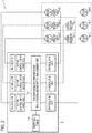
- the motor control apparatus 2 includes inverter (INV) circuits #1 to #3 including amplifier units, motor control units #1 to #3 that respectively control the motors #1 to #3, an encoder-sensor communication transmission-and-reception management unit 10, a non-volatile memory 11, and physical interfaces (IFs) #1 to #3.
- IOV inverter
- the amplifier unit is a power converter configured to supply a current or a voltage to the motors #1 to #3 based on a torque command from the motor control units #1 to #3, by switching (PWM control) of the inverter (INV) circuits #1 to #3.
- each of the motor control units #1 to #3 includes a motor control calculation unit 101, an encoder logical-axis interface 102, an external encoder logical-axis interface 103, and a sensor logical-axis interface 104.
- the motor control calculation unit 101 is configured to receive a command (position command and the like) from a host device and performs calculation for controlling positions, speeds, torques, and the like of the motors #1 to #3.
- the encoder logical-axis interface 102 is configured to read out constants of the motors #1 to #3 corresponding to the motor control units #1 to #3 to which the encoder logical-axis interface 102 belongs, and identification information (encoder ID information) of the encoders #1 to #3 corresponding to the motors #1 to #3, based on a mapping table which is managed by the encoder-sensor communication transmission-and-reception management unit 10 and is stored in the non-volatile memory 11.
- the encoder logical-axis interface 102 is configured to acquire position information of the motors #1 to #3 corresponding to the motor control units #1 to #3 to which the encoder logical-axis interface 102 belongs from the encoder #1 to #3 corresponding to the motors #1 to #3, based on the mapping table which is managed by the encoder-sensor communication transmission-and-reception management unit 10 and is stored in the non-volatile memory 11.
- the encoder logical-axis interface 102 in the motor control unit #1 is configured to acquire the motor constant or the position information of the motor #1 and the encoder ID information of the encoder #1 from the encoder-sensor communication transmission-and-reception management unit 10.
- the encoder logical-axis interface 102 in the motor control unit #2 is configured to acquire the motor constant or the position information of the motor #2 and the encoder ID information of the encoder #2 from the encoder-sensor communication transmission-and-reception management unit 10.
- the encoder logical-axis interface 102 in the motor control unit #3 is configured to acquire the motor constant or the position information of the motor #3 and the encoder ID information of the encoder #3 from the encoder-sensor communication transmission-and-reception management unit 10.
- the external encoder logical-axis interface 103 is configured to read out identification information (external encoder ID information) of the external encoders #4 and #5 corresponding to the motors #2 and #3 corresponding to the motor control units #1 to #3 to which the external encoder logical-axis interface 103 belongs, based on the mapping table which is managed by the encoder-sensor communication transmission-and-reception management unit 10 and is stored in the non-volatile memory 11.
- the external encoder logical-axis interface 103 is configured to acquire the position information of the mechanical apparatus that is driven by the motors #2 and #3 corresponding to the motor control units #2 and #3 to which the external encoder logical-axis interface 103 belongs, from the external encoders #4 and #5 corresponding to the mechanical apparatus that is driven by the motors #2 and #3.
- the acquisition is performed based on the mapping table which is managed by the encoder-sensor communication transmission-and-reception management unit 10 and is stored in the non-volatile memory 11.
- the external encoder logical-axis interface 103 in the motor control unit #2 is configured to acquire position information of the mechanical apparatus that is driven by the motor #2 or encoder ID information of the encoder #4, from the encoder-sensor communication transmission-and-reception management unit 10.
- the external encoder logical-axis interface 103 in the motor control unit #3 is configured to acquire position information of the mechanical apparatus that is driven by the motor #3 or encoder ID information of the encoder #5, from the encoder-sensor communication transmission-and-reception management unit 10.
- the sensor logical-axis interface 104 is configured to read out identification information (sensor ID information) of the sensors #6 to #8 corresponding to the motor control units #1 to #3 to which the sensor logical-axis interface 104 belongs, based on the mapping table managed by the encoder-sensor communication transmission-and-reception management units 10.
- the sensor logical-axis interface 104 is configured to read out sensor data of the sensors #6 to #8 corresponding to the motor control units #1 to #3 to which the sensor logical-axis interface 104 belongs, based on the mapping table managed by the encoder-sensor communication transmission-and-reception management units 10.
- the sensor data includes ON/OFF information and the like of the sensor, for example.
- the encoder-sensor communication transmission-and-reception management unit 10 is configured to manage communications with the encoders #1 to #5 or the sensors #6 to #8.
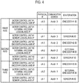
- the encoder-sensor communication transmission-and-reception management unit 10 is configured to manage the mapping table illustrated in Fig. 4 .
- mapping table is configured to be stored in a non-volatile memory such as an electrically erasable programmable read only memory (EEPROM).
- EEPROM electrically erasable programmable read only memory
- the identification information of the encoder #1 and the motor control unit #1 are associated with each other.
- the encoder logical-axis interface 102 of the motor control unit #1, the physical interface #3 (ch3), a communication address Addr.3, and the identification information of the encoder #1 are associated with each other.
- the identification information of the sensor #6 and the motor control unit #1 are associated with each other.
- the sensor logical-axis interface 104 of the motor control unit #1, a physical interface #1 (ch1), the communication address Addr.3, and the identification information of the sensor #6 are associated with each other.
- the external encoder is not provided.
- identification information of the external encoder and the motor control unit #1 (motor #1) are not associated with each other.
- the identification information of the encoder #2 and the motor control unit #2 are associated with each other.
- the encoder logical-axis interface 102 of the motor control unit #2, the physical interface #3 (ch3), a communication address Addr.2, and the identification information of the encoder #2 are associated with each other.
- the identification information of the encoder #4 (external encoder) and the motor control unit #2 (motor #2) are associated with each other.
- the external encoder logical-axis interface 103 of the motor control unit #2, a physical interface #2 (ch2), the communication address Addr.2, and the identification information of the encoder #4 are associated with each other.
- the identification information of the sensor #7 and the motor control unit #2 are associated with each other.
- the sensor logical-axis interface 104 of the motor control unit #2, the physical interface #1 (ch1), the communication address Addr.2, and the identification information of the sensor #7 are associated with each other.
- the identification information of the encoder #3 and the motor control unit #3 are associated with each other.
- the encoder logical-axis interface 102 of the motor control unit #3, the physical interface #3 (ch3), the communication address Addr.1, and the identification information of the encoder #3 are associated with each other.
- the identification information of the encoder #5 (external encoder) and the motor control unit #3 (motor #3) are associated with each other.
- the external encoder logical-axis interface 103 of the motor control unit #3, the physical interface #2 (ch2), the communication address Addr.1, and the identification information of the encoder #5 are associated with each other.
- the identification information of the sensor #8 and the motor control unit #3 are associated with each other.
- the sensor logical-axis interface 104 of the motor control unit #3, the physical interface #1 (ch1), the communication address Addr.1, and the identification information of the sensor #8 are associated with each other.
- the mapping table may be set in advance by a user, and the setting details may be preserved in the non-volatile memory 11 of the motor control apparatus 2.
- the encoder-sensor communication transmission-and-reception management unit 10 is configured to assign unique communication addresses to the encoders #1 to #3, the external encoders #4 and #5, and the sensors #6 to #8 based on the above-described mapping table.
- the encoder-sensor communication transmission-and-reception management unit 10 is configured to transfer the constants of the motors #1 to #3, the identification information of the encoders #1 to #3, the identification information of the external encoders #4 and #5, and the identification information of the sensors #6 to #8 to the corresponding encoder logical-axis interface 102, the corresponding external encoder logical-axis interface 103, or the corresponding sensor logical-axis interface 104, based on the above-described mapping table.
- the encoder-sensor communication transmission-and-reception management unit 10 is configured to transfer the position information of the motors #1 to #3, the position information of the mechanical apparatus that is driven by the motors #2 and #3, and the sensor data of the sensors #6 to #8 to the corresponding encoder logical-axis interface 102, the corresponding external encoder logical-axis interface 103, or the corresponding sensor logical-axis interface 104, based on the above-described mapping table.
- the physical interfaces #1 to #3 are configured to perform processing of transmitting and receiving data to and from devices (motor control apparatus, encoder, external encoder, sensor, and the like) other than the motor control apparatus 2 to which the physical interfaces #1 to #3 belong.
- the encoders #1 to #3 and the external encoders #4 and #5 may be optical encoders or magnetic encoders, for example.
- the encoders #1 to #3 and the external encoders #4 and #5 are configured to transmit the position information of the motors #1 to #3 or the position information of the mechanical apparatus that is driven by the motor #2 or #3, to the motor control apparatus 2.
- a case using the encoders #1 to #3 and the external encoders #4 and #5 as the position detector is described as an example.
- the present disclosure can be applied to a case using a sensor (for example, resolver) capable of detecting the position information of the motors #1 to #3 and the position information of the mechanical apparatus that is driven by the motors #2 and #3.
- the encoders #1 to #3 and the external encoders #4 and #5 may be linear scales (linear encoders) used in a case where the motors #1 to #3 are linear motors or linear scales (linear encoders) attached to the mechanical apparatus.
- the motors #1 to #3 may be rotary motors or linear motors.
- the above-described position information indicates a rotation angle.
- the above-described position information indicates a linear position.
- the mechanical apparatus is configured to be driven by the motors #1 to #3.
- a robot corresponds to the mechanical apparatus.
- the motors #1 to #3 are configured to respectively drive the first axis to the third axis of a three-axis robot as the mechanical apparatus.
- the sensors #6 to #8 are configured to detect information (sensor data) relating to at least any one of the motors #1 to #3 and the mechanical apparatus configured to be driven by the motors #1 to #3.
- information sensor data
- a temperature sensor, a pressure sensor, a torque sensor, a vibration sensor, a limit switch sensor, a touch sensor, and an I/O device are assumed as the plurality of sensors #6 to #8.
- the temperature sensor is a sensor configured to detect the temperature of at least any one of the mechanical apparatus and the motors #1 to #3 or the temperature in the vicinity of the mechanical apparatus or the motors #1 to #3.
- a temperature measuring resistor type sensor or a thermocouple type sensor may be used as the temperature sensor.
- the pressure sensor is a sensor configured to detect the pressure of at least any one of the mechanical apparatus and the motors #1 to #3 or the pressure in the vicinity of the mechanical apparatus or the motors #1 to #3.
- the pressure sensor is configured to measure the pressure with a pressure-sensitive element through a diaphragm (a stainless steel diaphragm, a silicon diaphragm, or the like) and to convert the measured pressure into an electrical signal and output the electrical signal.
- the torque sensor is a sensor configured to detect a torque of at least any one of the mechanical apparatus and the motors #1 to #3.
- the torque sensor may be a non-contact type torque sensor or a contact type torque sensor.
- the information (sensor data) relating to at least any one of the mechanical apparatus and the motors #1 to #3 means information which is not position information of the motors #1 to #3 among types of information regarding the state of at least any one of the mechanical apparatus and the motors #1 to #3.
- the information relating to at least any one of the mechanical apparatus and the motors #1 to #3 may be, for example, information which can be detected by the sensors #6 to #8.
- the information relating to at least any one of the mechanical apparatus and the motors #1 to #3 is information of the torques of the motors #1 to #3, the temperatures of the motors #1 to #3, a position of an object such as an arm, which is moved by the motors #1 to #3, pressure on the object, or the state (for example, temperature or ON/OFF information) of the sensors #6 to #8 that detect the above items.
- the association information regarding at least any one of the mechanical apparatus and the motors #1 to #3 is used for an output control of the motors #1 to #3 or for adjusting a control parameter or is used for determining whether or not a problem occurs in the motors #1 to #3 or predicting lifespans (remaining periods) of the motors #1 to #3.
- the encoders #1 to #3, the external encoders #4 and #5, and the sensors #6 to #8 are connected under a control of the motor control apparatus 2.
- the encoder #1 and the sensor #6 are connected in series under a control of the first axis of the motor control apparatus 2.
- the encoder #2, the external encoder #4, and the sensor #7 are connected in series under a control of the second axis of the motor control apparatus 2.
- the encoder #3, the external encoder #5, and the sensor #8 are connected in series under a control of the third axis of the motor control apparatus 2.
- a case where the three sensors #6 to #8 are provided is described as an example.
- the present disclosure can be applied to a case where any sensor is not provided, a case where two sensors or less are provided, a case where four sensors or more are provided, and the like.
- the motor control apparatus 2 is configured to automatically acquire the identification information of the encoders #1 to #3, the identification information of the external encoders #4 and #5, and the identification information of the sensors #6 to #8 and to store the identification information and the motor control units #1 to #3 in the non-volatile memory 11 in association with each other.
- the encoder-sensor communication transmission-and-reception management unit 10 in the motor control apparatus 2 is configured to automatically acquire the identification information of the sensors #6 to #8 through the physical interface #1 and to store the identification information and the motor control units #1 to #3 in the non-volatile memory 11 in association with each other.
- the encoder-sensor communication transmission-and-reception management unit 10 in the motor control apparatus 2 is configured to automatically acquire the identification information of the encoders #4 and #5 through the physical interface #2 and to store the identification information and the motor control units #2 and #3 in the non-volatile memory 11 in association with each other.
- the encoder-sensor communication transmission-and-reception management unit 10 in the motor control apparatus 2 is configured to automatically acquire the identification information of the encoders #1 to #3 through the physical interface #3 and to store the identification information and the motor control units #1 to #3 in the non-volatile memory 11 in association with each other.
- the motor control apparatus 2 may be configured to compare the identification information of the encoders #1 to #3, the identification information of the external encoders #4 and #5, or the identification information of the sensors #6 to #8, which have been acquired from the encoders #1 to #3, the external encoders #4 and #5, and the sensors #6 to #8 connected under the control of the motor control apparatus 2, to the identification information of the encoders #1 to #3, the identification information of the external encoders #4 and #5, or the identification information of the sensors #6 to #8, which have been stored in the non-volatile memory 11.
- the motor control apparatus 2 may be configured to check at least one of whether the encoders #1 to #3, the external encoders #4 and #5, and the sensors #6 to #8 operate as the above-described association and whether a connection configuration of the encoders #1 to #3, the external encoders #4 and #5, and the sensors #6 to #8 is not changed.
- the motor control apparatus 2 may be configured to instruct the encoders #1 to #3, the external encoders #4 and #5, or the sensors #6 to #8 to perform setting.
- the motor control apparatus 2 is configured to instruct the encoders #1 to #3 and the external encoders #4 and #5 to set an origin, set a multiturn limit, reset a multiturn, and the like.
- origin setting means that the origin is set to any position by a predetermined parameter in a case where an absolute linear encoder is used as the position detector.
- the user of the motor control apparatus 2 can set the predetermined parameter to be any value in accordance with the used mechanical apparatus.
- the multiturn limit is used, for example, for controlling the position of a rotating body such as a turntable by using an absolute encoder as the position detector.
- a rotating body such as a turntable
- the turntable rotates only in the one direction.
- the number of rotations of the turntable may exceed the upper limit of the number of rotations that can be counted by the absolute encoder.
- the multiturn limit is a parameter used such that fractions do not occur in an integer ratio relationship of the number of rotations of the motor and the number of rotations of the turntable, in this case.
- the user of the motor control apparatus 2 can set the parameter to any value in accordance with the mechanical apparatus to be used.
- the multiturn reset means initialization (initialization of multiturn data) of the absolute value encoder to be used.
- the motor control apparatus 2 is configured to start the motor control apparatus 20 again in a case where the above-described setting is performed and to check at least one of whether or not the encoders #1 to #3, the external encoders #4 and #5, or the sensors #6 to #8 operate as with the setting and whether or not predetermined operations of the motors #1 to #3 controlled by the motor control apparatus 2 are possible.
- the motor control apparatus 2 may be configured to check at least one of whether or not the encoders #1 to #3, the external encoders #4 and #5, or the sensors #6 to #8 operate as with the setting and whether or not predetermined operations of the motors #1 to #8 controlled by the motor control apparatus 2 are possible, in a case where the power of the motor control apparatus 2 is put again, or in a case where the motor control apparatus 2 is restored (alarm reset) from an abnormal state or changes a parameter that requires power on (that is, in a case where the motor control apparatus 2 is software-reset).
- Step S101 the motor control apparatus 2 automatically acquires and displays the identification information of the encoders #1 to #3, the identification information of the external encoders #4 and #5, and the identification information of the sensors #6 to #8, through the physical interfaces #1 to #3.
- Step S102 the motor control apparatus 2 sets association between the identification information and the logical-axis interfaces 102 to 104.
- Step S103 the motor control apparatus 2 generates the mapping table (see Fig. 4 ) and stores the mapping table in the non-volatile memory 11.
- the motor control apparatus 2 automatically searches for the encoders #1 to #3, the external encoders #4 and #5, and the sensors #6 to #8 connected under the control of the physical interfaces #1 to #3 of the motor control apparatus 2 in Step S202.
- Step S203 the motor control apparatus 2 compares the number of the encoders #1 to #3, the external encoders #4 and #5, and the sensors #6 to #8 connected under the control of the physical interface #1 to #3 of the motor control apparatus 2 to the managed number (number registered in the mapping table).
- Step S204 In a case where both the numbers are equal to each other, the process proceeds to Step S204. In a case where both the numbers are not equal to each other, the process proceeds to Step S206.
- Step S204 the motor control apparatus 2 acquires the identification information of the encoders #1 to #3, the external encoders #4 and #5, and the sensors #6 to #8 connected under the control of the physical interface #1 to #3 of the motor control apparatus 2.
- Step S205 the motor control apparatus 2 compares the acquired identification information to the managed identification information (identification information registered in the mapping table).
- Step S207 In a case where both pieces of identification information coincide with each other, the process proceeds to Step S207. In a case where both the pieces of identification information do not coincide with each other, the process proceeds to Step S206.
- Step S206 the motor control apparatus 2 displays abnormality and performs a notification of the abnormality.
- Step S207 the motor control apparatus 2 performs a normal operation.
- the motor control system 1 in the embodiment even in a case where the plurality of encoders and one or the plurality of sensors are configured to be connected in series under the control of the motor control apparatus 2, it is possible to appropriately realize the setting procedure of the motor control apparatus 2. As a result, it is possible to reduce a physical or processing cost.
Landscapes
- Engineering & Computer Science (AREA)
- Power Engineering (AREA)
- Automation & Control Theory (AREA)
- Physics & Mathematics (AREA)
- General Physics & Mathematics (AREA)
- Evolutionary Computation (AREA)
- Artificial Intelligence (AREA)
- Fuzzy Systems (AREA)
- Mathematical Physics (AREA)
- Software Systems (AREA)
- Robotics (AREA)
- Mechanical Engineering (AREA)
- Control Of Multiple Motors (AREA)
- Control Of Electric Motors In General (AREA)
- Control Of Motors That Do Not Use Commutators (AREA)
Abstract
Description
- The present disclosure relates to a motor control apparatus, a motor control method, and a motor control system.
-
Patent Literature 1 discloses a system in which a plurality of sensors are connected to an interface unit through respective communication paths, and a detection signal of each of the sensors is transmitted to a host controller or a motor control apparatus via a network that connects the host controller and the motor control apparatus to each other. -
Patent Literature 2 discloses a system in which a peripheral device that sets a parameter of a motor control apparatus or performs monitoring of the motor control apparatus through a communication unit in the motor control apparatus is connected. -
- Patent Literature 1:
JP H8-241111 A - Patent Literature 2:
JP H10-105206 A - However, there is a problem in that each sensor or each peripheral device is connected to a motor control apparatus, and thus a physical or processing cost tends to increase, in the system in the related art.
- The present disclosure has been made in consideration of the above circumstances, and an object of the present disclosure is to provide a motor control apparatus, a motor control method, and a motor control system, in which it is possible to reduce a physical or processing cost.
- The first aspect of the present disclosure is summarized as a motor control apparatus including: a motor control unit configured to control a motor, wherein the motor control apparatus is configured: to automatically acquire identification information of a plurality of position detectors, the position detectors being configured to be connected in series under a control of the motor control apparatus and to detect position information of the motor or position information of a mechanical apparatus configured to be driven by the motor, and to store the identification information and the motor control unit in a non-volatile memory in association with each other.
- The second aspect of the present disclosure is summarized as a motor control apparatus including: a motor control unit configured to control a motor, wherein the motor control apparatus is configured: to automatically acquire identification information of a position detector and a sensor connected in series under a control of the motor control apparatus, and to store the identification information and the motor control unit in a non-volatile memory in association with each other, the position detector is configured to detect position information of the motor or position information of a mechanical apparatus configured to be driven by the motor, and the sensor is configured to detect information relating to at least one of the motor and the mechanical apparatus configured to be driven by the motor.
- The third aspect of the present disclosure is summarized as a motor control method of controlling a motor, the method including: automatically acquiring identification information of a plurality of position detectors configured to be connected in series under a control of a motor control apparatus and to detect position information of the motor or position information of a mechanical apparatus configured to be driven by the motor, by the motor control apparatus; and storing the acquired identification information and the motor in a non-volatile memory in association with each other by the motor control apparatus.
- The fourth aspect of the present disclosure is summarized as a motor control method of controlling a motor, the method including: automatically acquiring identification information of a position detector configured to be connected in series under a control of a motor control apparatus and to detect position information of the motor or position information of a mechanical apparatus configured to be driven by the motor and automatically acquiring identification information of a sensor configured to be connected in series under the control of the motor control apparatus and to detect information relating to at least one of the mechanical apparatus and the motor, by the motor control apparatus; and storing the acquired identification information and the motor in a non-volatile memory in association with each other, by the motor control apparatus.
- The fifth aspect of the present disclosure is summarized as a motor control system including: a motor control apparatus including a motor control unit configured to control a motor; and a plurality of position detectors configured to be connected in series under a control of the motor control apparatus and to detect position information of the motor or position information of a mechanical apparatus configured to be driven by the motor, wherein the motor control apparatus is configured to automatically acquire identification information of the plurality of position detectors and to store the identification information and the motor control unit in the non-volatile memory in association with each other.
- The sixth aspect of the present disclosure is summarized as a motor control system including: a motor control apparatus including a motor control unit configured to control a motor; a mechanical apparatus configured to be driven by the motor; a position detector configured to detect position information of the motor or position information of the mechanical apparatus; and a sensor configured to detect information relating to at least one of the mechanical apparatus and the motor, wherein the motor control apparatus is configured: to automatically acquire identification information of the position detector and identification information of the sensor, the position detector and the sensor being connected in series under a control of the motor control apparatus, and to store the identification information and the motor control unit in a non-volatile memory in association with each other.
- According to the present disclosure, it is possible to provide a motor control apparatus, a motor control method, and a motor control system, in which it is possible to reduce a physical or processing cost.
-
-
Fig. 1 is a diagram illustrating an example of a hardware configuration of a motor control system according to an embodiment. -
Fig. 2 is a schematic diagram illustrating an example of an overall configuration of the motor control system according to the embodiment. -
Fig. 3 is a diagram illustrating an example of a function block of a motor control unit in a motor control apparatus constituting the motor control system according to the embodiment. -
Fig. 4 is a diagram illustrating an example of a mapping table managed by an encoder-sensor communication transmission-and-reception management unit of the motor control apparatus constituting the motor control system according to the embodiment. -
Fig. 5 is a diagram illustrating an operation of the motor control apparatus constituting the motor control system according to the embodiment. -
Fig. 6 is a diagram illustrating an operation of the motor control apparatus constituting the motor control system according to the embodiment. - According to the viewpoint of the inventor of the present invention, sensing of an operation situation in a motor control system has become more important in recent years. However, if the number of sensors increases, a physical cost for the number of wires and the like and a processing cost for traffic, processing loads, and the like increase. In particular, in a case where sensing is performed in real time, the costs tend to increase.
- As a result of intensive research and development to reduce the costs in the motor control system, the inventor of the present invention has conceived of a new and unique motor control system. Hereinafter, an example of a
motor control system 1 according to an embodiment will be described with reference toFigs. 1 to 6 . - In the present disclosure, the
motor control system 1 according to the embodiment is configured to control a plurality ofmotors # 1 to #3. As illustrated inFigs. 1 and2 , themotor control system 1 includes amotor control apparatus 2,motors # 1 to #3, a mechanical apparatus (not illustrated),encoders # 1 to #3 that detect position information of themotors # 1 to #3,encoders # 4 and #5 that detect position information of the mechanical apparatus, andsensors # 6 to #8. - In the embodiment, a case where one
motor control apparatus 2 that drives three axes of themotors # 1 to #3 is provided is described as an example. The present disclosure can be applied to a case where a plurality of motor control apparatuss are provided, or a motor control apparatus that drives one axis and the like. - The
motor control apparatus 2 is configured to control themotors # 1 to #3. Specifically, themotor control apparatus 2 is a device including a computer that controls an amplifier unit that outputs a current, a voltage, and the like to themotors # 1 to #3. That is, themotors # 1 to #3 are configured to rotate in accordance with the voltage or the current applied from the motor control apparatus 20. - Generally, the
motor control apparatus 2 that controls a servomotor is called as a servo-controller, a servo-amplifier, or the like. Themotor control apparatus 2 may be a device configured to control themotor 10, for example, may be an inverter. - Specifically, as illustrated in
Fig. 2 , themotor control apparatus 2 includes inverter (INV)circuits # 1 to #3 including amplifier units, motorcontrol units # 1 to #3 that respectively control themotors # 1 to #3, an encoder-sensor communication transmission-and-reception management unit 10, anon-volatile memory 11, and physical interfaces (IFs) #1 to #3. - The amplifier unit is a power converter configured to supply a current or a voltage to the
motors # 1 to #3 based on a torque command from the motorcontrol units # 1 to #3, by switching (PWM control) of the inverter (INV)circuits # 1 to #3. - Here, as illustrated in
Fig. 3 , each of the motorcontrol units # 1 to #3 includes a motorcontrol calculation unit 101, an encoder logical-axis interface 102, an external encoder logical-axis interface 103, and a sensor logical-axis interface 104. - The motor
control calculation unit 101 is configured to receive a command (position command and the like) from a host device and performs calculation for controlling positions, speeds, torques, and the like of themotors # 1 to #3. - The encoder logical-axis interface 102 is configured to read out constants of the
motors # 1 to #3 corresponding to the motorcontrol units # 1 to #3 to which the encoder logical-axis interface 102 belongs, and identification information (encoder ID information) of theencoders # 1 to #3 corresponding to themotors # 1 to #3, based on a mapping table which is managed by the encoder-sensor communication transmission-and-reception management unit 10 and is stored in thenon-volatile memory 11. - The encoder logical-axis interface 102 is configured to acquire position information of the
motors # 1 to #3 corresponding to the motorcontrol units # 1 to #3 to which the encoder logical-axis interface 102 belongs from theencoder # 1 to #3 corresponding to themotors # 1 to #3, based on the mapping table which is managed by the encoder-sensor communication transmission-and-reception management unit 10 and is stored in thenon-volatile memory 11. - Specifically, in the embodiment, the encoder logical-axis interface 102 in the motor
control unit # 1 is configured to acquire the motor constant or the position information of themotor # 1 and the encoder ID information of theencoder # 1 from the encoder-sensor communication transmission-and-reception management unit 10. - Similarly, the encoder logical-axis interface 102 in the motor
control unit # 2 is configured to acquire the motor constant or the position information of themotor # 2 and the encoder ID information of theencoder # 2 from the encoder-sensor communication transmission-and-reception management unit 10. - Similarly, the encoder logical-axis interface 102 in the motor
control unit # 3 is configured to acquire the motor constant or the position information of themotor # 3 and the encoder ID information of theencoder # 3 from the encoder-sensor communication transmission-and-reception management unit 10. - The external encoder logical-axis interface 103 is configured to read out identification information (external encoder ID information) of the
external encoders # 4 and #5 corresponding to themotors # 2 and #3 corresponding to the motorcontrol units # 1 to #3 to which the external encoder logical-axis interface 103 belongs, based on the mapping table which is managed by the encoder-sensor communication transmission-and-reception management unit 10 and is stored in thenon-volatile memory 11. - The external encoder logical-axis interface 103 is configured to acquire the position information of the mechanical apparatus that is driven by the
motors # 2 and #3 corresponding to the motorcontrol units # 2 and #3 to which the external encoder logical-axis interface 103 belongs, from theexternal encoders # 4 and #5 corresponding to the mechanical apparatus that is driven by themotors # 2 and #3. The acquisition is performed based on the mapping table which is managed by the encoder-sensor communication transmission-and-reception management unit 10 and is stored in thenon-volatile memory 11. - Specifically, in the embodiment, the external encoder logical-axis interface 103 in the motor
control unit # 2 is configured to acquire position information of the mechanical apparatus that is driven by themotor # 2 or encoder ID information of theencoder # 4, from the encoder-sensor communication transmission-and-reception management unit 10. - Similarly, the external encoder logical-axis interface 103 in the motor
control unit # 3 is configured to acquire position information of the mechanical apparatus that is driven by themotor # 3 or encoder ID information of theencoder # 5, from the encoder-sensor communication transmission-and-reception management unit 10. - The sensor logical-axis interface 104 is configured to read out identification information (sensor ID information) of the
sensors # 6 to #8 corresponding to the motorcontrol units # 1 to #3 to which the sensor logical-axis interface 104 belongs, based on the mapping table managed by the encoder-sensor communication transmission-and-reception management units 10. - The sensor logical-axis interface 104 is configured to read out sensor data of the
sensors # 6 to #8 corresponding to the motorcontrol units # 1 to #3 to which the sensor logical-axis interface 104 belongs, based on the mapping table managed by the encoder-sensor communication transmission-and-reception management units 10. Here, the sensor data includes ON/OFF information and the like of the sensor, for example. - The encoder-sensor communication transmission-and-
reception management unit 10 is configured to manage communications with theencoders # 1 to #5 or thesensors # 6 to #8. Here, the encoder-sensor communication transmission-and-reception management unit 10 is configured to manage the mapping table illustrated inFig. 4 . - The mapping table is configured to be stored in a non-volatile memory such as an electrically erasable programmable read only memory (EEPROM).
- In the example of a first axis in
Fig. 4 , the identification information of theencoder # 1 and the motor control unit #1 (motor #1) are associated with each other. Specifically, the encoder logical-axis interface 102 of the motorcontrol unit # 1, the physical interface #3 (ch3), a communication address Addr.3, and the identification information of theencoder # 1 are associated with each other. - Similarly, in the example of the first axis in
Fig. 4 , the identification information of thesensor # 6 and the motor control unit #1 (motor #1) are associated with each other. Specifically, the sensor logical-axis interface 104 of the motorcontrol unit # 1, a physical interface #1 (ch1), the communication address Addr.3, and the identification information of thesensor # 6 are associated with each other. - In the example of the first axis in
Fig. 4 , the external encoder is not provided. Thus, identification information of the external encoder and the motor control unit #1 (motor #1) are not associated with each other. - In the example of a second axis in
Fig. 4 , the identification information of theencoder # 2 and the motor control unit #2 (motor #2) are associated with each other. Specifically, the encoder logical-axis interface 102 of the motorcontrol unit # 2, the physical interface #3 (ch3), a communication address Addr.2, and the identification information of theencoder # 2 are associated with each other. - Similarly, in the example of the second axis in
Fig. 4 , the identification information of the encoder #4 (external encoder) and the motor control unit #2 (motor #2) are associated with each other. Specifically, the external encoder logical-axis interface 103 of the motorcontrol unit # 2, a physical interface #2 (ch2), the communication address Addr.2, and the identification information of theencoder # 4 are associated with each other. - Similarly, in the example of the second axis in
Fig. 4 , the identification information of thesensor # 7 and the motor control unit #2 (motor #2) are associated with each other. Specifically, the sensor logical-axis interface 104 of the motorcontrol unit # 2, the physical interface #1 (ch1), the communication address Addr.2, and the identification information of thesensor # 7 are associated with each other. - In the example of a third axis in
Fig. 4 , the identification information of theencoder # 3 and the motor control unit #3 (motor #3) are associated with each other. Specifically, the encoder logical-axis interface 102 of the motorcontrol unit # 3, the physical interface #3 (ch3), the communication address Addr.1, and the identification information of theencoder # 3 are associated with each other. - Similarly, in the example of the third axis in
Fig. 4 , the identification information of the encoder #5 (external encoder) and the motor control unit #3 (motor #3) are associated with each other. Specifically, the external encoder logical-axis interface 103 of the motorcontrol unit # 3, the physical interface #2 (ch2), the communication address Addr.1, and the identification information of theencoder # 5 are associated with each other. - Similarly, in the example of the third axis in
Fig. 4 , the identification information of thesensor # 8 and the motor control unit #3 (motor #3) are associated with each other. Specifically, the sensor logical-axis interface 104 of the motorcontrol unit # 3, the physical interface #1 (ch1), the communication address Addr.1, and the identification information of thesensor # 8 are associated with each other. - The mapping table may be set in advance by a user, and the setting details may be preserved in the
non-volatile memory 11 of themotor control apparatus 2. - For example, the encoder-sensor communication transmission-and-
reception management unit 10 is configured to assign unique communication addresses to theencoders # 1 to #3, theexternal encoders # 4 and #5, and thesensors # 6 to #8 based on the above-described mapping table. - The encoder-sensor communication transmission-and-
reception management unit 10 is configured to transfer the constants of themotors # 1 to #3, the identification information of theencoders # 1 to #3, the identification information of theexternal encoders # 4 and #5, and the identification information of thesensors # 6 to #8 to the corresponding encoder logical-axis interface 102, the corresponding external encoder logical-axis interface 103, or the corresponding sensor logical-axis interface 104, based on the above-described mapping table. - Similarly, the encoder-sensor communication transmission-and-
reception management unit 10 is configured to transfer the position information of themotors # 1 to #3, the position information of the mechanical apparatus that is driven by themotors # 2 and #3, and the sensor data of thesensors # 6 to #8 to the corresponding encoder logical-axis interface 102, the corresponding external encoder logical-axis interface 103, or the corresponding sensor logical-axis interface 104, based on the above-described mapping table. - The
physical interfaces # 1 to #3 are configured to perform processing of transmitting and receiving data to and from devices (motor control apparatus, encoder, external encoder, sensor, and the like) other than themotor control apparatus 2 to which thephysical interfaces # 1 to #3 belong. - Here, the
encoders # 1 to #3 and theexternal encoders # 4 and #5 may be optical encoders or magnetic encoders, for example. Theencoders # 1 to #3 and theexternal encoders # 4 and #5 are configured to transmit the position information of themotors # 1 to #3 or the position information of the mechanical apparatus that is driven by themotor # 2 or #3, to themotor control apparatus 2. - In the embodiment, a case using the
encoders # 1 to #3 and theexternal encoders # 4 and #5 as the position detector is described as an example. The present disclosure can be applied to a case using a sensor (for example, resolver) capable of detecting the position information of themotors # 1 to #3 and the position information of the mechanical apparatus that is driven by themotors # 2 and #3. Here, theencoders # 1 to #3 and theexternal encoders # 4 and #5 may be linear scales (linear encoders) used in a case where themotors # 1 to #3 are linear motors or linear scales (linear encoders) attached to the mechanical apparatus. - The
motors # 1 to #3 may be rotary motors or linear motors. Here, in a case where themotors # 1 to #3 are rotary motors, the above-described position information indicates a rotation angle. In a case where themotors # 1 to #3 are linear motors, the above-described position information indicates a linear position. - In the embodiment, a case where the
encoders # 1 to #3 and theexternal encoders # 4 and #5 are provided is described as an example. The present disclosure can be applied to a case where there is no limitation to the number of external encoders (for example, 0, 1, or three or more). - The mechanical apparatus is configured to be driven by the
motors # 1 to #3. For example, a robot corresponds to the mechanical apparatus. For example, in the embodiment, themotors # 1 to #3 are configured to respectively drive the first axis to the third axis of a three-axis robot as the mechanical apparatus. - The
sensors # 6 to #8 are configured to detect information (sensor data) relating to at least any one of themotors # 1 to #3 and the mechanical apparatus configured to be driven by themotors # 1 to #3. For example, a temperature sensor, a pressure sensor, a torque sensor, a vibration sensor, a limit switch sensor, a touch sensor, and an I/O device are assumed as the plurality ofsensors # 6 to #8. - The temperature sensor is a sensor configured to detect the temperature of at least any one of the mechanical apparatus and the
motors # 1 to #3 or the temperature in the vicinity of the mechanical apparatus or themotors # 1 to #3. For example, a temperature measuring resistor type sensor or a thermocouple type sensor may be used as the temperature sensor. - The pressure sensor is a sensor configured to detect the pressure of at least any one of the mechanical apparatus and the
motors # 1 to #3 or the pressure in the vicinity of the mechanical apparatus or themotors # 1 to #3. The pressure sensor is configured to measure the pressure with a pressure-sensitive element through a diaphragm (a stainless steel diaphragm, a silicon diaphragm, or the like) and to convert the measured pressure into an electrical signal and output the electrical signal. - The torque sensor is a sensor configured to detect a torque of at least any one of the mechanical apparatus and the
motors # 1 to #3. For example, the torque sensor may be a non-contact type torque sensor or a contact type torque sensor. - The information (sensor data) relating to at least any one of the mechanical apparatus and the
motors # 1 to #3 means information which is not position information of themotors # 1 to #3 among types of information regarding the state of at least any one of the mechanical apparatus and themotors # 1 to #3. The information relating to at least any one of the mechanical apparatus and themotors # 1 to #3 may be, for example, information which can be detected by thesensors # 6 to #8. - For example, the information relating to at least any one of the mechanical apparatus and the
motors # 1 to #3 is information of the torques of themotors # 1 to #3, the temperatures of themotors # 1 to #3, a position of an object such as an arm, which is moved by themotors # 1 to #3, pressure on the object, or the state (for example, temperature or ON/OFF information) of thesensors # 6 to #8 that detect the above items. - The association information regarding at least any one of the mechanical apparatus and the
motors # 1 to #3 is used for an output control of themotors # 1 to #3 or for adjusting a control parameter or is used for determining whether or not a problem occurs in themotors # 1 to #3 or predicting lifespans (remaining periods) of themotors # 1 to #3. - Here, as illustrated in
Fig. 2 , in themotor control system 1 according to the embodiment, theencoders # 1 to #3, theexternal encoders # 4 and #5, and thesensors # 6 to #8 are connected under a control of themotor control apparatus 2. - Specifically, in the
motor control system 1 according to the embodiment, as illustrated inFig. 1 , theencoder # 1 and thesensor # 6 are connected in series under a control of the first axis of themotor control apparatus 2. - Similarly, in the
motor control system 1 according to the embodiment, as illustrated inFig. 1 , theencoder # 2, theexternal encoder # 4, and thesensor # 7 are connected in series under a control of the second axis of themotor control apparatus 2. - Further, in the
motor control system 1 according to the embodiment, as illustrated inFig. 1 , theencoder # 3, theexternal encoder # 5, and thesensor # 8 are connected in series under a control of the third axis of themotor control apparatus 2. - In the embodiment, a case where the three
sensors # 6 to #8 are provided is described as an example. The present disclosure can be applied to a case where any sensor is not provided, a case where two sensors or less are provided, a case where four sensors or more are provided, and the like. - Here, the
motor control apparatus 2 is configured to automatically acquire the identification information of theencoders # 1 to #3, the identification information of theexternal encoders # 4 and #5, and the identification information of thesensors # 6 to #8 and to store the identification information and the motorcontrol units # 1 to #3 in thenon-volatile memory 11 in association with each other. - Specifically, the encoder-sensor communication transmission-and-
reception management unit 10 in themotor control apparatus 2 is configured to automatically acquire the identification information of thesensors # 6 to #8 through thephysical interface # 1 and to store the identification information and the motorcontrol units # 1 to #3 in thenon-volatile memory 11 in association with each other. - Similarly, the encoder-sensor communication transmission-and-
reception management unit 10 in themotor control apparatus 2 is configured to automatically acquire the identification information of theencoders # 4 and #5 through thephysical interface # 2 and to store the identification information and the motorcontrol units # 2 and #3 in thenon-volatile memory 11 in association with each other. - Similarly, the encoder-sensor communication transmission-and-
reception management unit 10 in themotor control apparatus 2 is configured to automatically acquire the identification information of theencoders # 1 to #3 through thephysical interface # 3 and to store the identification information and the motorcontrol units # 1 to #3 in thenon-volatile memory 11 in association with each other. - The
motor control apparatus 2 may be configured to compare the identification information of theencoders # 1 to #3, the identification information of theexternal encoders # 4 and #5, or the identification information of thesensors # 6 to #8, which have been acquired from theencoders # 1 to #3, theexternal encoders # 4 and #5, and thesensors # 6 to #8 connected under the control of themotor control apparatus 2, to the identification information of theencoders # 1 to #3, the identification information of theexternal encoders # 4 and #5, or the identification information of thesensors # 6 to #8, which have been stored in thenon-volatile memory 11. Thus, themotor control apparatus 2 may be configured to check at least one of whether theencoders # 1 to #3, theexternal encoders # 4 and #5, and thesensors # 6 to #8 operate as the above-described association and whether a connection configuration of theencoders # 1 to #3, theexternal encoders # 4 and #5, and thesensors # 6 to #8 is not changed. - Further, the
motor control apparatus 2 may be configured to instruct theencoders # 1 to #3, theexternal encoders # 4 and #5, or thesensors # 6 to #8 to perform setting. For example, themotor control apparatus 2 is configured to instruct theencoders # 1 to #3 and theexternal encoders # 4 and #5 to set an origin, set a multiturn limit, reset a multiturn, and the like. - Here, the origin is a zero point in a coordinate system of the mechanical apparatus that is driven by the
motors # 1 to #3. For example, origin setting means that the origin is set to any position by a predetermined parameter in a case where an absolute linear encoder is used as the position detector. The user of themotor control apparatus 2 can set the predetermined parameter to be any value in accordance with the used mechanical apparatus. - The multiturn limit is used, for example, for controlling the position of a rotating body such as a turntable by using an absolute encoder as the position detector. In a case where a mechanical apparatus that moves the turntable only in one direction is assumed, the turntable rotates only in the one direction. Thus, the number of rotations of the turntable may exceed the upper limit of the number of rotations that can be counted by the absolute encoder. The multiturn limit is a parameter used such that fractions do not occur in an integer ratio relationship of the number of rotations of the motor and the number of rotations of the turntable, in this case. The user of the
motor control apparatus 2 can set the parameter to any value in accordance with the mechanical apparatus to be used. - The multiturn reset means initialization (initialization of multiturn data) of the absolute value encoder to be used.
- The
motor control apparatus 2 is configured to start the motor control apparatus 20 again in a case where the above-described setting is performed and to check at least one of whether or not theencoders # 1 to #3, theexternal encoders # 4 and #5, or thesensors # 6 to #8 operate as with the setting and whether or not predetermined operations of themotors # 1 to #3 controlled by themotor control apparatus 2 are possible. - The
motor control apparatus 2 may be configured to check at least one of whether or not theencoders # 1 to #3, theexternal encoders # 4 and #5, or thesensors # 6 to #8 operate as with the setting and whether or not predetermined operations of themotors # 1 to #8 controlled by themotor control apparatus 2 are possible, in a case where the power of themotor control apparatus 2 is put again, or in a case where themotor control apparatus 2 is restored (alarm reset) from an abnormal state or changes a parameter that requires power on (that is, in a case where themotor control apparatus 2 is software-reset). - Next, an example of an operation of the
motor control apparatus 2 constituting themotor control system 1 according to the embodiment will be described with reference toFigs. 5 and 6 . - As illustrated in
Fig. 5 , in Step S101, themotor control apparatus 2 automatically acquires and displays the identification information of theencoders # 1 to #3, the identification information of theexternal encoders # 4 and #5, and the identification information of thesensors # 6 to #8, through thephysical interfaces # 1 to #3. - In Step S102, the
motor control apparatus 2 sets association between the identification information and the logical-axis interfaces 102 to 104. In Step S103, themotor control apparatus 2 generates the mapping table (seeFig. 4 ) and stores the mapping table in thenon-volatile memory 11. - As illustrated in
Fig. 6 , if the power is put into themotor control apparatus 2 in Step S201, themotor control apparatus 2 automatically searches for theencoders # 1 to #3, theexternal encoders # 4 and #5, and thesensors # 6 to #8 connected under the control of thephysical interfaces # 1 to #3 of themotor control apparatus 2 in Step S202. - In Step S203, the
motor control apparatus 2 compares the number of theencoders # 1 to #3, theexternal encoders # 4 and #5, and thesensors # 6 to #8 connected under the control of thephysical interface # 1 to #3 of themotor control apparatus 2 to the managed number (number registered in the mapping table). - In a case where both the numbers are equal to each other, the process proceeds to Step S204. In a case where both the numbers are not equal to each other, the process proceeds to Step S206.
- In Step S204, the
motor control apparatus 2 acquires the identification information of theencoders # 1 to #3, theexternal encoders # 4 and #5, and thesensors # 6 to #8 connected under the control of thephysical interface # 1 to #3 of themotor control apparatus 2. - In Step S205, the
motor control apparatus 2 compares the acquired identification information to the managed identification information (identification information registered in the mapping table). - In a case where both pieces of identification information coincide with each other, the process proceeds to Step S207. In a case where both the pieces of identification information do not coincide with each other, the process proceeds to Step S206.
- In Step S206, the
motor control apparatus 2 displays abnormality and performs a notification of the abnormality. In Step S207, themotor control apparatus 2 performs a normal operation. - According to the
motor control system 1 in the embodiment, even in a case where the plurality of encoders and one or the plurality of sensors are configured to be connected in series under the control of themotor control apparatus 2, it is possible to appropriately realize the setting procedure of themotor control apparatus 2. As a result, it is possible to reduce a physical or processing cost. -
- 1
- motor control system
- 2
- motor control apparatus
- 10
- encoder-sensor communication transmission-and-reception management unit
- 11
- non-volatile memory
- 101
- motor control calculation unit
- 102
- encoder logical-axis interface
- 103
- external encoder logical-axis interface
- 104
- sensor logical-axis interface
Claims (8)
- A motor control apparatus comprising:a motor control unit configured to control a motor, whereinthe motor control apparatus is configured:to automatically acquire identification information of a plurality of position detectors, the position detectors being configured to be connected in series under a control of the motor control apparatus and to detect position information of the motor or position information of a mechanical apparatus configured to be driven by the motor, andto store the identification information and the motor control unit in a non-volatile memory in association with each other.
- The motor control apparatus according to claim 1, wherein
the motor control apparatus is configured:to compare the identification information of the plurality of position detectors, which has been acquired from the plurality of position detectors connected under the control of the motor control apparatus, to identification information of the plurality of position detectors, which has been stored in the non-volatile memory, andto check at least one of whether the position detectors operate in accordance with the association and whether a connection configuration of the plurality of position detectors is not changed. - A motor control apparatus comprising:a motor control unit configured to control a motor, whereinthe motor control apparatus is configured:to automatically acquire identification information of a position detector and a sensor connected in series under a control of the motor control apparatus, andto store the identification information and the motor control unit in a non-volatile memory in association with each other,the position detector is configured to detect position information of the motor or position information of a mechanical apparatus configured to be driven by the motor, andthe sensor is configured to detect information relating to at least one of the motor and the mechanical apparatus configured to be driven by the motor.
- The motor control apparatus according to claim 3, wherein
the motor control apparatus is configured:to compare identification information of the position detector and identification information of the sensor, which have been acquired from the position detector and the sensor connected under a control of the motor control apparatus, to the identification information of the position detector and the identification information of the sensor, which have been stored in the non-volatile memory, andto check at least one of whether the position detector and the sensor operate in accordance with the association and whether a connection configuration of the position detector and the sensor is not changed. - A motor control method of controlling a motor, the method comprising:automatically acquiring identification information of a plurality of position detectors configured to be connected in series under a control of a motor control apparatus and to detect position information of the motor or position information of a mechanical apparatus configured to be driven by the motor, by the motor control apparatus; andstoring the acquired identification information and the motor in a non-volatile memory in association with each other by the motor control apparatus.
- A motor control method of controlling a motor, the method comprising:automatically acquiring identification information of a position detector configured to be connected in series under a control of a motor control apparatus and to detect position information of the motor or position information of a mechanical apparatus configured to be driven by the motor and automatically acquiring identification information of a sensor configured to be connected in series under the control of the motor control apparatus and to detect information relating to at least one of the mechanical apparatus and the motor, by the motor control apparatus; andstoring the acquired identification information and the motor in a non-volatile memory in association with each other, by the motor control apparatus.
- A motor control system comprising:a motor control apparatus including a motor control unit configured to control a motor; anda plurality of position detectors configured to be connected in series under a control of the motor control apparatus and to detect position information of the motor or position information of a mechanical apparatus configured to be driven by the motor, whereinthe motor control apparatus is configured to automatically acquire identification information of the plurality of position detectors and to store the identification information and the motor control unit in the non-volatile memory in association with each other.
- A motor control system comprising:a motor control apparatus including a motor control unit configured to control a motor;a mechanical apparatus configured to be driven by the motor;a position detector configured to detect position information of the motor or position information of the mechanical apparatus; anda sensor configured to detect information relating to at least one of the mechanical apparatus and the motor, whereinthe motor control apparatus is configured:to automatically acquire identification information of the position detector and identification information of the sensor, the position detector and the sensor being connected in series under a control of the motor control apparatus, andto store the identification information and the motor control unit in a non-volatile memory in association with each other.
Applications Claiming Priority (1)
| Application Number | Priority Date | Filing Date | Title |
|---|---|---|---|
| PCT/JP2017/013818 WO2018179418A1 (en) | 2017-03-31 | 2017-03-31 | Motor control device, motor control method, and motor control system |
Publications (3)
| Publication Number | Publication Date |
|---|---|
| EP3605828A1 true EP3605828A1 (en) | 2020-02-05 |
| EP3605828A4 EP3605828A4 (en) | 2020-11-11 |
| EP3605828B1 EP3605828B1 (en) | 2025-06-25 |
Family
ID=62106111
Family Applications (1)
| Application Number | Title | Priority Date | Filing Date |
|---|---|---|---|
| EP17903987.0A Active EP3605828B1 (en) | 2017-03-31 | 2017-03-31 | Motor control system and motor control method |
Country Status (5)
| Country | Link |
|---|---|
| US (1) | US11316461B2 (en) |
| EP (1) | EP3605828B1 (en) |
| JP (1) | JP6319519B1 (en) |
| CN (1) | CN110463016B (en) |
| WO (1) | WO2018179418A1 (en) |
Family Cites Families (11)
| Publication number | Priority date | Publication date | Assignee | Title |
|---|---|---|---|---|
| JPH07114402A (en) * | 1993-10-14 | 1995-05-02 | Fanuc Ltd | Parameter automatic setting system for servo motor |
| JP3481339B2 (en) | 1995-03-03 | 2003-12-22 | 三菱電機株式会社 | Drive control system |
| JP3439930B2 (en) | 1996-10-02 | 2003-08-25 | 三菱電機株式会社 | Servo motor drive control device and servo amplifier, peripheral device, servo motor position detector |
| JP4175377B2 (en) * | 1997-10-08 | 2008-11-05 | 株式会社デンソーウェーブ | Robot controller |
| JP3682508B2 (en) * | 1999-11-25 | 2005-08-10 | 株式会社日立製作所 | Control device for vehicle power converter |
| JP2004280506A (en) * | 2003-03-17 | 2004-10-07 | Fanuc Ltd | Numerical control device |
| DE102004011457B4 (en) * | 2004-03-09 | 2020-03-05 | Siemens Aktiengesellschaft | Actuator and method for operating an actuator |
| JP4825283B2 (en) * | 2009-04-02 | 2011-11-30 | 三菱電機株式会社 | Engine control device |
| JP4853842B2 (en) * | 2010-01-12 | 2012-01-11 | 株式会社安川電機 | Synchronous control device |
| JP2013070524A (en) * | 2011-09-22 | 2013-04-18 | Toshiba Corp | Motor control circuit and motor control system |
| JP5905532B2 (en) * | 2014-07-09 | 2016-04-20 | ファナック株式会社 | Control system including a control device for controlling a machine having a plurality of axes |
-
2017
- 2017-03-31 WO PCT/JP2017/013818 patent/WO2018179418A1/en not_active Ceased
- 2017-03-31 CN CN201780089114.XA patent/CN110463016B/en active Active
- 2017-03-31 JP JP2017534618A patent/JP6319519B1/en active Active
- 2017-03-31 EP EP17903987.0A patent/EP3605828B1/en active Active
-
2019
- 2019-09-30 US US16/587,059 patent/US11316461B2/en active Active
Also Published As
| Publication number | Publication date |
|---|---|
| US11316461B2 (en) | 2022-04-26 |
| JPWO2018179418A1 (en) | 2019-04-11 |
| CN110463016A (en) | 2019-11-15 |
| EP3605828B1 (en) | 2025-06-25 |
| WO2018179418A1 (en) | 2018-10-04 |
| US20200028461A1 (en) | 2020-01-23 |
| EP3605828A4 (en) | 2020-11-11 |
| CN110463016B (en) | 2023-01-20 |
| JP6319519B1 (en) | 2018-05-09 |
Similar Documents
| Publication | Publication Date | Title |
|---|---|---|
| EP2559135B1 (en) | Battery management system and method for transferring data within the battery management system | |
| US8626960B2 (en) | Industrial controller interface for plug-in I/O modules | |
| US10921108B2 (en) | Method for monitoring a magnetic bearing apparatus | |
| US10055618B1 (en) | RFID reader for RFID sensors | |
| CN109115346A (en) | A kind of rotatable parts temperature monitoring system | |
| EP3777045B1 (en) | Integration of diagnostic instrumentation with machine protection system | |
| US11181881B2 (en) | Motor control system, control method, and motor control apparatus | |
| EP3776121B1 (en) | Flexible condition monitoring of industrial machines | |
| US10422668B2 (en) | Method and program for angle calibration of rotary shaft | |
| US11316461B2 (en) | Motor control apparatus, motor control method, and motor control system | |
| US9151598B2 (en) | Position measuring device | |
| EP3539221A1 (en) | Slip ring with selective wear indication | |
| EP3605836B1 (en) | Motor control system and input/output device | |
| JP5037437B2 (en) | Encoder with internal information output function | |
| US8280691B2 (en) | Arrangement for evaluating the measured values of a measured-value converter | |
| EP3015933A1 (en) | Transport system | |
| CN213812571U (en) | Intelligent vibration transmitter | |
| EP3240998B1 (en) | Programmable sensor | |
| JP2022111732A (en) | Control system, programmable controller, and operation control module | |
| JP2022138348A (en) | Servo driver and servo system | |
| RU164862U1 (en) | DEVICE FOR DETERMINING ANGLE OF TURNING THE PLATFORM OF THE LIFTING AND TRANSPORT MACHINE |
Legal Events
| Date | Code | Title | Description |
|---|---|---|---|
| STAA | Information on the status of an ep patent application or granted ep patent |
Free format text: STATUS: THE INTERNATIONAL PUBLICATION HAS BEEN MADE |
|
| PUAI | Public reference made under article 153(3) epc to a published international application that has entered the european phase |
Free format text: ORIGINAL CODE: 0009012 |
|
| STAA | Information on the status of an ep patent application or granted ep patent |
Free format text: STATUS: REQUEST FOR EXAMINATION WAS MADE |
|
| 17P | Request for examination filed |
Effective date: 20191024 |
|
| AK | Designated contracting states |
Kind code of ref document: A1 Designated state(s): AL AT BE BG CH CY CZ DE DK EE ES FI FR GB GR HR HU IE IS IT LI LT LU LV MC MK MT NL NO PL PT RO RS SE SI SK SM TR |
|
| AX | Request for extension of the european patent |
Extension state: BA ME |
|
| DAV | Request for validation of the european patent (deleted) | ||
| DAX | Request for extension of the european patent (deleted) | ||
| A4 | Supplementary search report drawn up and despatched |
Effective date: 20201008 |
|
| RIC1 | Information provided on ipc code assigned before grant |
Ipc: G05B 19/048 20060101ALI20201002BHEP Ipc: H02P 6/04 20160101ALI20201002BHEP Ipc: H02P 29/024 20160101ALI20201002BHEP Ipc: H02P 5/46 20060101AFI20201002BHEP Ipc: H02P 23/00 20160101ALI20201002BHEP |
|
| STAA | Information on the status of an ep patent application or granted ep patent |
Free format text: STATUS: EXAMINATION IS IN PROGRESS |
|
| 17Q | First examination report despatched |
Effective date: 20220408 |
|
| REG | Reference to a national code |
Ref country code: DE Free format text: PREVIOUS MAIN CLASS: H02P0006040000 Ref country code: DE Ref legal event code: R079 Ref document number: 602017090195 Country of ref document: DE Free format text: PREVIOUS MAIN CLASS: H02P0006040000 Ipc: H02P0005460000 |
|
| GRAP | Despatch of communication of intention to grant a patent |
Free format text: ORIGINAL CODE: EPIDOSNIGR1 |
|
| STAA | Information on the status of an ep patent application or granted ep patent |
Free format text: STATUS: GRANT OF PATENT IS INTENDED |
|
| RIC1 | Information provided on ipc code assigned before grant |
Ipc: G05B 19/414 20060101ALN20250218BHEP Ipc: G05B 19/048 20060101ALN20250218BHEP Ipc: H02P 6/04 20160101ALI20250218BHEP Ipc: H02P 29/024 20160101ALI20250218BHEP Ipc: H02P 23/00 20160101ALI20250218BHEP Ipc: H02P 5/46 20060101AFI20250218BHEP |
|
| RIC1 | Information provided on ipc code assigned before grant |
Ipc: G05B 19/414 20060101ALN20250227BHEP Ipc: G05B 19/048 20060101ALN20250227BHEP Ipc: H02P 6/04 20160101ALI20250227BHEP Ipc: H02P 29/024 20160101ALI20250227BHEP Ipc: H02P 23/00 20160101ALI20250227BHEP Ipc: H02P 5/46 20060101AFI20250227BHEP |
|
| INTG | Intention to grant announced |
Effective date: 20250314 |
|
| GRAS | Grant fee paid |
Free format text: ORIGINAL CODE: EPIDOSNIGR3 |
|
| GRAA | (expected) grant |
Free format text: ORIGINAL CODE: 0009210 |
|
| STAA | Information on the status of an ep patent application or granted ep patent |
Free format text: STATUS: THE PATENT HAS BEEN GRANTED |
|
| AK | Designated contracting states |
Kind code of ref document: B1 Designated state(s): AL AT BE BG CH CY CZ DE DK EE ES FI FR GB GR HR HU IE IS IT LI LT LU LV MC MK MT NL NO PL PT RO RS SE SI SK SM TR |
|
| REG | Reference to a national code |
Ref country code: GB Ref legal event code: FG4D |
|
| REG | Reference to a national code |
Ref country code: CH Ref legal event code: EP |
|
| REG | Reference to a national code |
Ref country code: CH Ref legal event code: EP |
|
| REG | Reference to a national code |
Ref country code: IE Ref legal event code: FG4D |
|
| REG | Reference to a national code |
Ref country code: DE Ref legal event code: R096 Ref document number: 602017090195 Country of ref document: DE |
|
| PG25 | Lapsed in a contracting state [announced via postgrant information from national office to epo] |
Ref country code: FI Free format text: LAPSE BECAUSE OF FAILURE TO SUBMIT A TRANSLATION OF THE DESCRIPTION OR TO PAY THE FEE WITHIN THE PRESCRIBED TIME-LIMIT Effective date: 20250625 |
|
| REG | Reference to a national code |
Ref country code: LT Ref legal event code: MG9D |
|
| PG25 | Lapsed in a contracting state [announced via postgrant information from national office to epo] |
Ref country code: NO Free format text: LAPSE BECAUSE OF FAILURE TO SUBMIT A TRANSLATION OF THE DESCRIPTION OR TO PAY THE FEE WITHIN THE PRESCRIBED TIME-LIMIT Effective date: 20250925 Ref country code: GR Free format text: LAPSE BECAUSE OF FAILURE TO SUBMIT A TRANSLATION OF THE DESCRIPTION OR TO PAY THE FEE WITHIN THE PRESCRIBED TIME-LIMIT Effective date: 20250926 |
|
| PG25 | Lapsed in a contracting state [announced via postgrant information from national office to epo] |
Ref country code: BG Free format text: LAPSE BECAUSE OF FAILURE TO SUBMIT A TRANSLATION OF THE DESCRIPTION OR TO PAY THE FEE WITHIN THE PRESCRIBED TIME-LIMIT Effective date: 20250625 |
|
| PG25 | Lapsed in a contracting state [announced via postgrant information from national office to epo] |
Ref country code: HR Free format text: LAPSE BECAUSE OF FAILURE TO SUBMIT A TRANSLATION OF THE DESCRIPTION OR TO PAY THE FEE WITHIN THE PRESCRIBED TIME-LIMIT Effective date: 20250625 |
|
| PG25 | Lapsed in a contracting state [announced via postgrant information from national office to epo] |
Ref country code: RS Free format text: LAPSE BECAUSE OF FAILURE TO SUBMIT A TRANSLATION OF THE DESCRIPTION OR TO PAY THE FEE WITHIN THE PRESCRIBED TIME-LIMIT Effective date: 20250925 |
|
| PG25 | Lapsed in a contracting state [announced via postgrant information from national office to epo] |
Ref country code: LV Free format text: LAPSE BECAUSE OF FAILURE TO SUBMIT A TRANSLATION OF THE DESCRIPTION OR TO PAY THE FEE WITHIN THE PRESCRIBED TIME-LIMIT Effective date: 20250625 |
|
| REG | Reference to a national code |
Ref country code: NL Ref legal event code: MP Effective date: 20250625 |
|
| PG25 | Lapsed in a contracting state [announced via postgrant information from national office to epo] |
Ref country code: NL Free format text: LAPSE BECAUSE OF FAILURE TO SUBMIT A TRANSLATION OF THE DESCRIPTION OR TO PAY THE FEE WITHIN THE PRESCRIBED TIME-LIMIT Effective date: 20250625 |
|
| PG25 | Lapsed in a contracting state [announced via postgrant information from national office to epo] |
Ref country code: PT Free format text: LAPSE BECAUSE OF FAILURE TO SUBMIT A TRANSLATION OF THE DESCRIPTION OR TO PAY THE FEE WITHIN THE PRESCRIBED TIME-LIMIT Effective date: 20251027 |
|
| REG | Reference to a national code |
Ref country code: AT Ref legal event code: MK05 Ref document number: 1807649 Country of ref document: AT Kind code of ref document: T Effective date: 20250625 |
|
| PG25 | Lapsed in a contracting state [announced via postgrant information from national office to epo] |
Ref country code: IS Free format text: LAPSE BECAUSE OF FAILURE TO SUBMIT A TRANSLATION OF THE DESCRIPTION OR TO PAY THE FEE WITHIN THE PRESCRIBED TIME-LIMIT Effective date: 20251025 |
|
| PG25 | Lapsed in a contracting state [announced via postgrant information from national office to epo] |
Ref country code: AT Free format text: LAPSE BECAUSE OF FAILURE TO SUBMIT A TRANSLATION OF THE DESCRIPTION OR TO PAY THE FEE WITHIN THE PRESCRIBED TIME-LIMIT Effective date: 20250625 Ref country code: SM Free format text: LAPSE BECAUSE OF FAILURE TO SUBMIT A TRANSLATION OF THE DESCRIPTION OR TO PAY THE FEE WITHIN THE PRESCRIBED TIME-LIMIT Effective date: 20250625 |
|
| PG25 | Lapsed in a contracting state [announced via postgrant information from national office to epo] |
Ref country code: CZ Free format text: LAPSE BECAUSE OF FAILURE TO SUBMIT A TRANSLATION OF THE DESCRIPTION OR TO PAY THE FEE WITHIN THE PRESCRIBED TIME-LIMIT Effective date: 20250625 |
|
| PG25 | Lapsed in a contracting state [announced via postgrant information from national office to epo] |
Ref country code: PL Free format text: LAPSE BECAUSE OF FAILURE TO SUBMIT A TRANSLATION OF THE DESCRIPTION OR TO PAY THE FEE WITHIN THE PRESCRIBED TIME-LIMIT Effective date: 20250625 |
|
| PG25 | Lapsed in a contracting state [announced via postgrant information from national office to epo] |
Ref country code: EE Free format text: LAPSE BECAUSE OF FAILURE TO SUBMIT A TRANSLATION OF THE DESCRIPTION OR TO PAY THE FEE WITHIN THE PRESCRIBED TIME-LIMIT Effective date: 20250625 |
|
| PG25 | Lapsed in a contracting state [announced via postgrant information from national office to epo] |
Ref country code: SK Free format text: LAPSE BECAUSE OF FAILURE TO SUBMIT A TRANSLATION OF THE DESCRIPTION OR TO PAY THE FEE WITHIN THE PRESCRIBED TIME-LIMIT Effective date: 20250625 |
|
| PG25 | Lapsed in a contracting state [announced via postgrant information from national office to epo] |
Ref country code: ES Free format text: LAPSE BECAUSE OF FAILURE TO SUBMIT A TRANSLATION OF THE DESCRIPTION OR TO PAY THE FEE WITHIN THE PRESCRIBED TIME-LIMIT Effective date: 20250625 |
|
| PG25 | Lapsed in a contracting state [announced via postgrant information from national office to epo] |
Ref country code: DK Free format text: LAPSE BECAUSE OF FAILURE TO SUBMIT A TRANSLATION OF THE DESCRIPTION OR TO PAY THE FEE WITHIN THE PRESCRIBED TIME-LIMIT Effective date: 20250625 |
|
| PGFP | Annual fee paid to national office [announced via postgrant information from national office to epo] |
Ref country code: DE Payment date: 20260326 Year of fee payment: 10 |
|
| PG25 | Lapsed in a contracting state [announced via postgrant information from national office to epo] |
Ref country code: IT Free format text: LAPSE BECAUSE OF FAILURE TO SUBMIT A TRANSLATION OF THE DESCRIPTION OR TO PAY THE FEE WITHIN THE PRESCRIBED TIME-LIMIT Effective date: 20250625 |
|
| PLBE | No opposition filed within time limit |
Free format text: ORIGINAL CODE: 0009261 |
|
| STAA | Information on the status of an ep patent application or granted ep patent |
Free format text: STATUS: NO OPPOSITION FILED WITHIN TIME LIMIT |
|
| REG | Reference to a national code |
Ref country code: CH Ref legal event code: L10 Free format text: ST27 STATUS EVENT CODE: U-0-0-L10-L00 (AS PROVIDED BY THE NATIONAL OFFICE) Effective date: 20260507 |