EP3605753A1 - Doped fiber amplifier and work method thereof - Google Patents
Doped fiber amplifier and work method thereof Download PDFInfo
- Publication number
- EP3605753A1 EP3605753A1 EP17902503.6A EP17902503A EP3605753A1 EP 3605753 A1 EP3605753 A1 EP 3605753A1 EP 17902503 A EP17902503 A EP 17902503A EP 3605753 A1 EP3605753 A1 EP 3605753A1
- Authority
- EP
- European Patent Office
- Prior art keywords
- doped fiber
- isolator
- fiber amplifier
- signal light
- coupler
- Prior art date
- Legal status (The legal status is an assumption and is not a legal conclusion. Google has not performed a legal analysis and makes no representation as to the accuracy of the status listed.)
- Granted
Links
Images
Classifications
-
- H—ELECTRICITY
- H01—ELECTRIC ELEMENTS
- H01S—DEVICES USING THE PROCESS OF LIGHT AMPLIFICATION BY STIMULATED EMISSION OF RADIATION [LASER] TO AMPLIFY OR GENERATE LIGHT; DEVICES USING STIMULATED EMISSION OF ELECTROMAGNETIC RADIATION IN WAVE RANGES OTHER THAN OPTICAL
- H01S3/00—Lasers, i.e. devices using stimulated emission of electromagnetic radiation in the infrared, visible or ultraviolet wave range
- H01S3/09—Processes or apparatus for excitation, e.g. pumping
- H01S3/091—Processes or apparatus for excitation, e.g. pumping using optical pumping
- H01S3/094—Processes or apparatus for excitation, e.g. pumping using optical pumping by coherent light
-
- H—ELECTRICITY
- H01—ELECTRIC ELEMENTS
- H01S—DEVICES USING THE PROCESS OF LIGHT AMPLIFICATION BY STIMULATED EMISSION OF RADIATION [LASER] TO AMPLIFY OR GENERATE LIGHT; DEVICES USING STIMULATED EMISSION OF ELECTROMAGNETIC RADIATION IN WAVE RANGES OTHER THAN OPTICAL
- H01S3/00—Lasers, i.e. devices using stimulated emission of electromagnetic radiation in the infrared, visible or ultraviolet wave range
- H01S3/05—Construction or shape of optical resonators; Accommodation of active medium therein; Shape of active medium
- H01S3/06—Construction or shape of active medium
- H01S3/063—Waveguide lasers, i.e. whereby the dimensions of the waveguide are of the order of the light wavelength
- H01S3/067—Fibre lasers
- H01S3/06754—Fibre amplifiers
-
- H—ELECTRICITY
- H01—ELECTRIC ELEMENTS
- H01S—DEVICES USING THE PROCESS OF LIGHT AMPLIFICATION BY STIMULATED EMISSION OF RADIATION [LASER] TO AMPLIFY OR GENERATE LIGHT; DEVICES USING STIMULATED EMISSION OF ELECTROMAGNETIC RADIATION IN WAVE RANGES OTHER THAN OPTICAL
- H01S3/00—Lasers, i.e. devices using stimulated emission of electromagnetic radiation in the infrared, visible or ultraviolet wave range
- H01S3/05—Construction or shape of optical resonators; Accommodation of active medium therein; Shape of active medium
- H01S3/06—Construction or shape of active medium
- H01S3/063—Waveguide lasers, i.e. whereby the dimensions of the waveguide are of the order of the light wavelength
- H01S3/067—Fibre lasers
- H01S3/06708—Constructional details of the fibre, e.g. compositions, cross-section, shape or tapering
- H01S3/06716—Fibre compositions or doping with active elements
-
- H—ELECTRICITY
- H01—ELECTRIC ELEMENTS
- H01S—DEVICES USING THE PROCESS OF LIGHT AMPLIFICATION BY STIMULATED EMISSION OF RADIATION [LASER] TO AMPLIFY OR GENERATE LIGHT; DEVICES USING STIMULATED EMISSION OF ELECTROMAGNETIC RADIATION IN WAVE RANGES OTHER THAN OPTICAL
- H01S3/00—Lasers, i.e. devices using stimulated emission of electromagnetic radiation in the infrared, visible or ultraviolet wave range
- H01S3/09—Processes or apparatus for excitation, e.g. pumping
- H01S3/091—Processes or apparatus for excitation, e.g. pumping using optical pumping
- H01S3/094—Processes or apparatus for excitation, e.g. pumping using optical pumping by coherent light
- H01S3/094003—Processes or apparatus for excitation, e.g. pumping using optical pumping by coherent light the pumped medium being a fibre
-
- H—ELECTRICITY
- H01—ELECTRIC ELEMENTS
- H01S—DEVICES USING THE PROCESS OF LIGHT AMPLIFICATION BY STIMULATED EMISSION OF RADIATION [LASER] TO AMPLIFY OR GENERATE LIGHT; DEVICES USING STIMULATED EMISSION OF ELECTROMAGNETIC RADIATION IN WAVE RANGES OTHER THAN OPTICAL
- H01S3/00—Lasers, i.e. devices using stimulated emission of electromagnetic radiation in the infrared, visible or ultraviolet wave range
- H01S3/10—Controlling the intensity, frequency, phase, polarisation or direction of the emitted radiation, e.g. switching, gating, modulating or demodulating
- H01S3/13—Stabilisation of laser output parameters, e.g. frequency or amplitude
- H01S3/1301—Stabilisation of laser output parameters, e.g. frequency or amplitude in optical amplifiers
Definitions
- the present disclosure relates to a field of pluggable laser radar light source technology, and in particular to a doped optical fiber amplifier and working method thereof.
- a laser radar is a radar system that emits a laser beam to detect a position and velocity of a target.
- most of the laser radar light sources use a semiconductor laser with a wavelength of 905 nm.
- a frequency of the laser radar light sources is low, the safety threshold of the human eye is low, and the light source adopts an asynchronous operation mode during scanning.
- the erbium doped fiber amplifier is designed as a single-stage erbium doped fiber amplifier with forward 980 nm and back 1480 nm bidirectional pumping.
- the technical problem to be solved by the present disclosure is to provide a doped fiber amplifier and a working method thereof for realizing 1550 nm signal light amplification by a pump laser by using a rare earth doped fiber.
- the present disclosure provides a doped fiber amplifier including a seed source inputting signal light, a first isolator connected with the seed source, a coupler connected with the first isolator, a pump laser and a doped fiber connected with the coupler, a second isolator connected with the doped fiber, an optical splitter connected with the second isolator, a connection head connected with the optical splitter.
- the connection head outputs the signal light of the seed source.
- the optical splitter includes main path signal optical fibers and branch path signal optical fibers. All of the main path signal optical fibers are connected with the second isolator and the connection head.
- the doped fiber amplifier includes a detector connected with the branch path signal optical fiber of the optical splitter
- the detector is a photodiode.
- the seed source is a laser with a wavelength of 1550 nm.
- the coupler is a wavelength divider.
- the doped fiber is doped dilute fiber.
- the doped fiber amplifier is arranged in a pluggable optical module housing.
- the present disclosure provides a working method includes steps:
- the present disclosure realizes 1550 nm signal light amplification by the pump laser with the use of the doped dilute fiber, and a repetition frequency of the 1550 nm laser can reach megahertz.
- the laser has a high-water absorption coefficient, when the wavelength laser irradiates person eyes, the damage threshold to the human eyes is high, thus, the laser of the band has human eyes safety characteristics.
- the light source uses a standard pluggable optical module package form, and has broad application prospects in fields of automatic driving and 3D scanning.
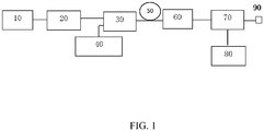
- FIG. 1 is a schematic diagram showing a structure of a doped fiber amplifier of the present disclosure.
- the present disclosure provides a doped fiber amplifier including a seed source 10 inputting signal light, a first isolator 20 connected with the seed source 10, a coupler 30 connected with the first isolator 20, a pump laser 40 and a doped fiber 50 connected with the coupler 30, a second isolator 60 connected with the doped fiber 50, an optical splitter 70 connected with the second isolator 60, a detector 80 connected with the optical splitter 70, and a connection head 90 connected with the optical splitter 70.
- the connection head 90 outputs the signal light of the seed source 10.
- the coupler 30 is a wavelength divider.
- the function of the coupler 30 is to couple an input signal and a pump light into the doped fiber 50, and transfers an energy of the pump light into the input optical signal through the doped fiber 50 to realize amplification of the input optical signal.
- the doped fiber 50 is doped dilute fiber 50.
- Dilute ions are activated to amplify the optical signal in a 1550 nm operating window with low optical transmission loss.
- the seed source is a laser with a wavelength of 1550 nm.
- a pigtail (fiber) of the seed source 10 is welded with a pigtail (fiber) of the first isolator 20.
- the pigtail (fiber) of the first isolator 20 is welded with a pigtail (signal fiber) of the coupler 30.
- a pigtail (fiber) of the pump laser 40 is welded with a pigtail (pump fiber) of the coupler 30.
- the doped fiber 50 is welded with a pigtail (fiber) of the second isolator 60.
- the optical splitter 70 includes main path signal optical fibers and branch path signal optical fibers.
- the pigtail (fiber) of the second isolator 60 is fused with a pigtail (main signal fiber) of the optical splitter 70.
- a pigtail (shunt signal fiber) of the optical splitter 70 is fused with a pigtail (fiber) of the detector 80.
- a pigtail (main road signal fiber) of the optical splitter 70 is welded with an output terminal connector 90 (optical fiber).
- the detector 80 ensures that the entire doped fiber amplifier operates within a predetermined output optical power.
- the detector is a photodiode.
- the present disclosure provides a working method includes steps:
- the present disclosure realizes 1550 nm signal light amplification by the pump laser 40 with the use of doped dilute fiber 50, and the repetition frequency of the 1550 nm laser can reach megahertz. Further, the laser has a high-water absorption coefficient, when the wavelength laser irradiates person eyes, the damage threshold to the human eyes is high, thus, the laser of the band has human eyes safety characteristics.
- the light source uses a standard pluggable optical module package form, and has broad application prospects in fields of automatic driving and 3D scanning.
- the optics and electronics of the laser radar source are packaged in standard pluggable optical module housings (e.g. SFP, SFP+, XFP, CFP, CFP2, etc.), which is communicated and module controlled using standard MSA protocols through gold fingers.
- standard pluggable optical module housings e.g. SFP, SFP+, XFP, CFP, CFP2, etc.
Landscapes
- Physics & Mathematics (AREA)
- Electromagnetism (AREA)
- Engineering & Computer Science (AREA)
- Plasma & Fusion (AREA)
- Optics & Photonics (AREA)
- Lasers (AREA)
- Optical Couplings Of Light Guides (AREA)
Abstract
Description
- The present disclosure relates to a field of pluggable laser radar light source technology, and in particular to a doped optical fiber amplifier and working method thereof.
- A laser radar is a radar system that emits a laser beam to detect a position and velocity of a target. At present, most of the laser radar light sources use a semiconductor laser with a wavelength of 905 nm. However, a frequency of the laser radar light sources is low, the safety threshold of the human eye is low, and the light source adopts an asynchronous operation mode during scanning. At present, the erbium doped fiber amplifier (EDFA) is designed as a single-stage erbium doped fiber amplifier with forward 980 nm and back 1480 nm bidirectional pumping.
- The technical problem to be solved by the present disclosure is to provide a doped fiber amplifier and a working method thereof for realizing 1550 nm signal light amplification by a pump laser by using a rare earth doped fiber.
- The present disclosure provides a doped fiber amplifier including a seed source inputting signal light, a first isolator connected with the seed source, a coupler connected with the first isolator, a pump laser and a doped fiber connected with the coupler, a second isolator connected with the doped fiber, an optical splitter connected with the second isolator, a connection head connected with the optical splitter. The connection head outputs the signal light of the seed source.
- Furthermore, the optical splitter includes main path signal optical fibers and branch path signal optical fibers. All of the main path signal optical fibers are connected with the second isolator and the connection head.
- Furthermore, the doped fiber amplifier includes a detector connected with the branch path signal optical fiber of the optical splitter
- Furthermore, the detector is a photodiode.
- Furthermore, the seed source is a laser with a wavelength of 1550 nm.
- Furthermore, the coupler is a wavelength divider.
- Furthermore, the doped fiber is doped dilute fiber.
- Furthermore, the doped fiber amplifier is arranged in a pluggable optical module housing.
- The present disclosure provides a working method includes steps:
- emitting signal light, from a seed source to a first isolator;
- passing through the first isolator, and the signal light is transmitted to a coupler unidirectionally;
- providing energy to the coupler by a pump laser;
- coupling the input signal light and energies provided by the pump laser into a doped fiber by the coupler;
- inputting the signal light and the energies to a second isolator by the doped fiber, and passing through the second isolator to the optical splitter unidirectionally; and
- outputting the signal light from the optical splitter through a detector, while outputting the signal light to a connector.
- The present disclosure realizes 1550 nm signal light amplification by the pump laser with the use of the doped dilute fiber, and a repetition frequency of the 1550 nm laser can reach megahertz. Further, the laser has a high-water absorption coefficient, when the wavelength laser irradiates person eyes, the damage threshold to the human eyes is high, thus, the laser of the band has human eyes safety characteristics. In addition, the light source uses a standard pluggable optical module package form, and has broad application prospects in fields of automatic driving and 3D scanning.
-
FIG. 1 is a schematic diagram showing a structure of a doped fiber amplifier of the present disclosure. - As shown in
FIG. 1 , the present disclosure provides a doped fiber amplifier including aseed source 10 inputting signal light, afirst isolator 20 connected with theseed source 10, a coupler 30 connected with thefirst isolator 20, apump laser 40 and a dopedfiber 50 connected with the coupler 30, asecond isolator 60 connected with the dopedfiber 50, anoptical splitter 70 connected with thesecond isolator 60, adetector 80 connected with theoptical splitter 70, and aconnection head 90 connected with theoptical splitter 70. Theconnection head 90 outputs the signal light of theseed source 10. - In one embodiment, the coupler 30 is a wavelength divider. The function of the coupler 30 is to couple an input signal and a pump light into the doped
fiber 50, and transfers an energy of the pump light into the input optical signal through the dopedfiber 50 to realize amplification of the input optical signal. - In one embodiment, the doped
fiber 50 is dopeddilute fiber 50. Dilute ions are activated to amplify the optical signal in a 1550 nm operating window with low optical transmission loss. - In one embodiment, the seed source is a laser with a wavelength of 1550 nm. A pigtail (fiber) of the
seed source 10 is welded with a pigtail (fiber) of thefirst isolator 20. The pigtail (fiber) of thefirst isolator 20 is welded with a pigtail (signal fiber) of the coupler 30. A pigtail (fiber) of thepump laser 40 is welded with a pigtail (pump fiber) of the coupler 30. The dopedfiber 50 is welded with a pigtail (fiber) of thesecond isolator 60. - In one embodiment, the
optical splitter 70 includes main path signal optical fibers and branch path signal optical fibers. The pigtail (fiber) of thesecond isolator 60 is fused with a pigtail (main signal fiber) of theoptical splitter 70. A pigtail (shunt signal fiber) of theoptical splitter 70 is fused with a pigtail (fiber) of thedetector 80. A pigtail (main road signal fiber) of theoptical splitter 70 is welded with an output terminal connector 90 (optical fiber). - In one embodiment, the
detector 80 ensures that the entire doped fiber amplifier operates within a predetermined output optical power. The detector is a photodiode. - The present disclosure provides a working method includes steps:
- Step 1: emitting signal light, from a
seed source 10 to afirst isolator 20; - Step 2: passing through the
first isolator 20, and the signal light is transmitted to a coupler 30 unidirectionally; - Step 3: providing energy to the coupler 30 by a
pump laser 40; - Step 4: coupling the input signal light and energies provided by the
pump laser 40 into the dopedfiber 50 by the coupler 30; - Step 5: inputting the signal light and the energies to a
second isolator 60 by the dopedfiber 50, and passing through thesecond isolator 60 to theoptical splitter 70 unidirectionally; and - Step 6: outputting the signal light from the
optical splitter 70 through a detector, while outputting the signal light to a connector. - The present disclosure realizes 1550 nm signal light amplification by the
pump laser 40 with the use of dopeddilute fiber 50, and the repetition frequency of the 1550 nm laser can reach megahertz. Further, the laser has a high-water absorption coefficient, when the wavelength laser irradiates person eyes, the damage threshold to the human eyes is high, thus, the laser of the band has human eyes safety characteristics. In addition, the light source uses a standard pluggable optical module package form, and has broad application prospects in fields of automatic driving and 3D scanning. - The optics and electronics of the laser radar source are packaged in standard pluggable optical module housings (e.g. SFP, SFP+, XFP, CFP, CFP2, etc.), which is communicated and module controlled using standard MSA protocols through gold fingers.
- The above content is a further detailed description of the present disclosure in conjunction with the specific preferred embodiments, and the specific implementation of the present disclosure is not limited to the description. It will be apparent that equivalent changes or modifications made in accordance with the scope of the present disclosure, which should be considered as being within the scope of the present disclosure.
Claims (9)
- A doped fiber amplifier comprising a seed source inputting signal light, a first isolator connected with the seed source, a coupler connected with the first isolator, a pump laser and a doped fiber connected with the coupler, a second isolator connected with the doped fiber, an optical splitter connected with the second isolator, and a connection head connected with the optical splitter; wherein the connection head outputs the signal light of the seed source.
- The doped fiber amplifier according to claim 1, wherein the optical splitter comprises main path signal optical fibers and branch path signal optical fibers, all of the main path signal optical fibers are connected with the second isolator and the connection head.
- The doped fiber amplifier according to claim 2, wherein the doped fiber amplifier comprising a detector connected with the branch path signal optical fiber of the optical splitter
- The doped fiber amplifier according to claim 3, wherein the detector is a photodiode.
- The doped fiber amplifier according to claim 1, wherein the seed source is a laser with a wavelength of 1550 nm.
- The doped fiber amplifier according to claim 1, wherein the coupler is a wavelength divider.
- The doped fiber amplifier according to claim 1, wherein the doped fiber is doped dilute fiber.
- The doped fiber amplifier according to claim 1, wherein the doped fiber amplifier is arranged in a pluggable optical module housing.
- A working method according to any claims 1 to 8, comprising steps:emitting signal light, from a seed source to a first isolator;passing through the first isolator, and the signal light is transmitted to a coupler unidirectionally;providing energy to the coupler by a pump laser;coupling the input signal light and energies provided by the pump laser into a doped fiber by the coupler;inputting the signal light and the energies to a second isolator by the doped fiber, and passing through the second isolator to the optical splitter unidirectionally; andoutputting the signal light from the optical splitter through a detector, while outputting the signal light to a connector.
Applications Claiming Priority (2)
| Application Number | Priority Date | Filing Date | Title |
|---|---|---|---|
| CN201710184416.7A CN106961065A (en) | 2017-03-24 | 2017-03-24 | Doped optical fibre amplifier and method of work |
| PCT/CN2017/109282 WO2018171206A1 (en) | 2017-03-24 | 2017-11-03 | Doped fiber amplifier and work method thereof |
Publications (3)
| Publication Number | Publication Date |
|---|---|
| EP3605753A1 true EP3605753A1 (en) | 2020-02-05 |
| EP3605753A4 EP3605753A4 (en) | 2020-04-29 |
| EP3605753B1 EP3605753B1 (en) | 2022-01-12 |
Family
ID=59471747
Family Applications (1)
| Application Number | Title | Priority Date | Filing Date |
|---|---|---|---|
| EP17902503.6A Not-in-force EP3605753B1 (en) | 2017-03-24 | 2017-11-03 | Doped fiber amplifier and work method thereof |
Country Status (6)
| Country | Link |
|---|---|
| US (1) | US20200006911A1 (en) |
| EP (1) | EP3605753B1 (en) |
| CN (1) | CN106961065A (en) |
| AU (2) | AU2017404913A1 (en) |
| CA (1) | CA3056169A1 (en) |
| WO (1) | WO2018171206A1 (en) |
Families Citing this family (3)
| Publication number | Priority date | Publication date | Assignee | Title |
|---|---|---|---|---|
| CN107037533A (en) * | 2017-03-24 | 2017-08-11 | 昂纳信息技术(深圳)有限公司 | Array laser radar light-dividing device and its light-splitting method |
| CN106961065A (en) * | 2017-03-24 | 2017-07-18 | 昂纳信息技术(深圳)有限公司 | Doped optical fibre amplifier and method of work |
| CN109061657A (en) * | 2018-08-13 | 2018-12-21 | 昂纳信息技术(深圳)有限公司 | A kind of solid state light emitter of laser radar and a kind of laser radar |
Family Cites Families (8)
| Publication number | Priority date | Publication date | Assignee | Title |
|---|---|---|---|---|
| KR980013060A (en) * | 1996-07-15 | 1998-04-30 | 김광호 | An optical fiber amplifying device for amplifying transmission light by bi-directionally exciting pump power |
| CN101083381A (en) * | 2006-05-30 | 2007-12-05 | 中国科学院西安光学精密机械研究所 | Diode Laser Seed Pulse Master Oscillator Amplified All-fiber Laser |
| CN100571080C (en) * | 2006-11-06 | 2009-12-16 | 中国科学院上海光学精密机械研究所 | Signal source device with 1053nm wavelength, high power and narrow line width |
| CN101330191A (en) * | 2008-07-28 | 2008-12-24 | 深圳市明鑫科技发展有限公司 | SF pulse optical fibre laser and method for generating SF pulse seeds laser |
| CN101950913A (en) * | 2010-08-12 | 2011-01-19 | 上海拜安实业有限公司 | Fiber laser source based on pulse seed source amplification and fiber sensing system |
| US9819143B2 (en) * | 2013-06-21 | 2017-11-14 | Nufern | Method and apparatus for polarization determination and/or control in optical fiber amplifying systems |
| CN105406330A (en) * | 2015-11-19 | 2016-03-16 | 深圳市镭神智能系统有限公司 | 1550nm Q-switched pulse erbium-ytterbium co-doped fiber laser device |
| CN106961065A (en) * | 2017-03-24 | 2017-07-18 | 昂纳信息技术(深圳)有限公司 | Doped optical fibre amplifier and method of work |
-
2017
- 2017-03-24 CN CN201710184416.7A patent/CN106961065A/en active Pending
- 2017-11-03 EP EP17902503.6A patent/EP3605753B1/en not_active Not-in-force
- 2017-11-03 AU AU2017404913A patent/AU2017404913A1/en active Pending
- 2017-11-03 WO PCT/CN2017/109282 patent/WO2018171206A1/en not_active Ceased
- 2017-11-03 CA CA3056169A patent/CA3056169A1/en not_active Abandoned
- 2017-11-03 AU AU2017101904A patent/AU2017101904A4/en not_active Ceased
-
2019
- 2019-08-12 US US16/537,650 patent/US20200006911A1/en not_active Abandoned
Also Published As
| Publication number | Publication date |
|---|---|
| US20200006911A1 (en) | 2020-01-02 |
| AU2017101904A4 (en) | 2021-07-29 |
| EP3605753B1 (en) | 2022-01-12 |
| WO2018171206A1 (en) | 2018-09-27 |
| AU2017404913A2 (en) | 2021-05-13 |
| CA3056169A1 (en) | 2018-09-27 |
| CN106961065A (en) | 2017-07-18 |
| AU2017404913A1 (en) | 2019-10-24 |
| EP3605753A4 (en) | 2020-04-29 |
Similar Documents
| Publication | Publication Date | Title |
|---|---|---|
| CN108493747A (en) | 2 μm of high-energy pure-tone pulse lasers based on optical fiber solid Cascaded amplification | |
| US20200006911A1 (en) | Doped Optical Fiber Amplifier And Working Method Thereof | |
| WO2017129939A3 (en) | Apparatus and method for optical isolation | |
| CN110233413A (en) | A kind of multi-Wavelength Pulses optical fiber laser and laser radar system | |
| JPH06120899A (en) | Optical communication system with monitoring device for avoiding giant pulse | |
| CN212908503U (en) | Optical fiber type narrow linewidth optical fiber laser | |
| US10855044B2 (en) | Optical amplifier | |
| CN112600061A (en) | Tunable Raman fiber laser | |
| CN105633780A (en) | Mode locking optical fiber laser amplification system on the basis of chirp optical fiber grating | |
| CN109298425B (en) | Multifunctional laser sensing system | |
| CN221709113U (en) | Fiber laser device for laser radar | |
| CN113659414A (en) | Pulse fiber laser device applied to laser radar | |
| CN107037533A (en) | Array laser radar light-dividing device and its light-splitting method | |
| CN104733988A (en) | MOPA pulse fiber laser based on pulse drive superluminescent diodes | |
| CN217281617U (en) | Pulse width adjustable optical fiber laser | |
| CN106099635A (en) | The 2 mu m waveband linear polarization single frequency optical fiber lasers with power feedback mechanism | |
| CN213905814U (en) | Tunable Raman fiber laser | |
| CN113690724A (en) | An ultra-short pulse source for non-ferrous metal processing | |
| CN204575907U (en) | A kind of forward direction optoelectric hybrid device of Erbium-Doped Fiber Amplifier (EDFA) | |
| CN111829653A (en) | Measuring device for output light beam of fiber laser and using method thereof | |
| CN105914572A (en) | High altitude sodium layer wind temperature detection laser radar emission laser system | |
| CN113675713B (en) | Near-infrared erbium-doped fiber laser | |
| Peng et al. | All-fiber eye-safe pulsed laser with Er-Yb Co-doped multi-stage amplifier | |
| CN103746282A (en) | Laser | |
| CN115395348A (en) | Fiber laser for simply monitoring output power |
Legal Events
| Date | Code | Title | Description |
|---|---|---|---|
| STAA | Information on the status of an ep patent application or granted ep patent |
Free format text: STATUS: THE INTERNATIONAL PUBLICATION HAS BEEN MADE |
|
| PUAI | Public reference made under article 153(3) epc to a published international application that has entered the european phase |
Free format text: ORIGINAL CODE: 0009012 |
|
| STAA | Information on the status of an ep patent application or granted ep patent |
Free format text: STATUS: REQUEST FOR EXAMINATION WAS MADE |
|
| 17P | Request for examination filed |
Effective date: 20190827 |
|
| AK | Designated contracting states |
Kind code of ref document: A1 Designated state(s): AL AT BE BG CH CY CZ DE DK EE ES FI FR GB GR HR HU IE IS IT LI LT LU LV MC MK MT NL NO PL PT RO RS SE SI SK SM TR |
|
| AX | Request for extension of the european patent |
Extension state: BA ME |
|
| A4 | Supplementary search report drawn up and despatched |
Effective date: 20200326 |
|
| RIC1 | Information provided on ipc code assigned before grant |
Ipc: H01S 3/067 20060101AFI20200321BHEP |
|
| DAV | Request for validation of the european patent (deleted) | ||
| DAX | Request for extension of the european patent (deleted) | ||
| GRAP | Despatch of communication of intention to grant a patent |
Free format text: ORIGINAL CODE: EPIDOSNIGR1 |
|
| STAA | Information on the status of an ep patent application or granted ep patent |
Free format text: STATUS: GRANT OF PATENT IS INTENDED |
|
| INTG | Intention to grant announced |
Effective date: 20210817 |
|
| GRAS | Grant fee paid |
Free format text: ORIGINAL CODE: EPIDOSNIGR3 |
|
| GRAA | (expected) grant |
Free format text: ORIGINAL CODE: 0009210 |
|
| STAA | Information on the status of an ep patent application or granted ep patent |
Free format text: STATUS: THE PATENT HAS BEEN GRANTED |
|
| AK | Designated contracting states |
Kind code of ref document: B1 Designated state(s): AL AT BE BG CH CY CZ DE DK EE ES FI FR GB GR HR HU IE IS IT LI LT LU LV MC MK MT NL NO PL PT RO RS SE SI SK SM TR |
|
| REG | Reference to a national code |
Ref country code: GB Ref legal event code: FG4D |
|
| REG | Reference to a national code |
Ref country code: CH Ref legal event code: EP |
|
| REG | Reference to a national code |
Ref country code: DE Ref legal event code: R096 Ref document number: 602017052401 Country of ref document: DE |
|
| REG | Reference to a national code |
Ref country code: IE Ref legal event code: FG4D |
|
| REG | Reference to a national code |
Ref country code: AT Ref legal event code: REF Ref document number: 1462995 Country of ref document: AT Kind code of ref document: T Effective date: 20220215 |
|
| REG | Reference to a national code |
Ref country code: LT Ref legal event code: MG9D |
|
| REG | Reference to a national code |
Ref country code: NL Ref legal event code: MP Effective date: 20220112 |
|
| REG | Reference to a national code |
Ref country code: AT Ref legal event code: MK05 Ref document number: 1462995 Country of ref document: AT Kind code of ref document: T Effective date: 20220112 |
|
| PG25 | Lapsed in a contracting state [announced via postgrant information from national office to epo] |
Ref country code: NL Free format text: LAPSE BECAUSE OF FAILURE TO SUBMIT A TRANSLATION OF THE DESCRIPTION OR TO PAY THE FEE WITHIN THE PRESCRIBED TIME-LIMIT Effective date: 20220112 |
|
| PG25 | Lapsed in a contracting state [announced via postgrant information from national office to epo] |
Ref country code: SE Free format text: LAPSE BECAUSE OF FAILURE TO SUBMIT A TRANSLATION OF THE DESCRIPTION OR TO PAY THE FEE WITHIN THE PRESCRIBED TIME-LIMIT Effective date: 20220112 Ref country code: RS Free format text: LAPSE BECAUSE OF FAILURE TO SUBMIT A TRANSLATION OF THE DESCRIPTION OR TO PAY THE FEE WITHIN THE PRESCRIBED TIME-LIMIT Effective date: 20220112 Ref country code: PT Free format text: LAPSE BECAUSE OF FAILURE TO SUBMIT A TRANSLATION OF THE DESCRIPTION OR TO PAY THE FEE WITHIN THE PRESCRIBED TIME-LIMIT Effective date: 20220512 Ref country code: NO Free format text: LAPSE BECAUSE OF FAILURE TO SUBMIT A TRANSLATION OF THE DESCRIPTION OR TO PAY THE FEE WITHIN THE PRESCRIBED TIME-LIMIT Effective date: 20220412 Ref country code: LT Free format text: LAPSE BECAUSE OF FAILURE TO SUBMIT A TRANSLATION OF THE DESCRIPTION OR TO PAY THE FEE WITHIN THE PRESCRIBED TIME-LIMIT Effective date: 20220112 Ref country code: HR Free format text: LAPSE BECAUSE OF FAILURE TO SUBMIT A TRANSLATION OF THE DESCRIPTION OR TO PAY THE FEE WITHIN THE PRESCRIBED TIME-LIMIT Effective date: 20220112 Ref country code: ES Free format text: LAPSE BECAUSE OF FAILURE TO SUBMIT A TRANSLATION OF THE DESCRIPTION OR TO PAY THE FEE WITHIN THE PRESCRIBED TIME-LIMIT Effective date: 20220112 Ref country code: BG Free format text: LAPSE BECAUSE OF FAILURE TO SUBMIT A TRANSLATION OF THE DESCRIPTION OR TO PAY THE FEE WITHIN THE PRESCRIBED TIME-LIMIT Effective date: 20220412 |
|
| PG25 | Lapsed in a contracting state [announced via postgrant information from national office to epo] |
Ref country code: PL Free format text: LAPSE BECAUSE OF FAILURE TO SUBMIT A TRANSLATION OF THE DESCRIPTION OR TO PAY THE FEE WITHIN THE PRESCRIBED TIME-LIMIT Effective date: 20220112 Ref country code: LV Free format text: LAPSE BECAUSE OF FAILURE TO SUBMIT A TRANSLATION OF THE DESCRIPTION OR TO PAY THE FEE WITHIN THE PRESCRIBED TIME-LIMIT Effective date: 20220112 Ref country code: GR Free format text: LAPSE BECAUSE OF FAILURE TO SUBMIT A TRANSLATION OF THE DESCRIPTION OR TO PAY THE FEE WITHIN THE PRESCRIBED TIME-LIMIT Effective date: 20220413 Ref country code: FI Free format text: LAPSE BECAUSE OF FAILURE TO SUBMIT A TRANSLATION OF THE DESCRIPTION OR TO PAY THE FEE WITHIN THE PRESCRIBED TIME-LIMIT Effective date: 20220112 Ref country code: AT Free format text: LAPSE BECAUSE OF FAILURE TO SUBMIT A TRANSLATION OF THE DESCRIPTION OR TO PAY THE FEE WITHIN THE PRESCRIBED TIME-LIMIT Effective date: 20220112 |
|
| PG25 | Lapsed in a contracting state [announced via postgrant information from national office to epo] |
Ref country code: IS Free format text: LAPSE BECAUSE OF FAILURE TO SUBMIT A TRANSLATION OF THE DESCRIPTION OR TO PAY THE FEE WITHIN THE PRESCRIBED TIME-LIMIT Effective date: 20220512 |
|
| REG | Reference to a national code |
Ref country code: DE Ref legal event code: R097 Ref document number: 602017052401 Country of ref document: DE |
|
| PG25 | Lapsed in a contracting state [announced via postgrant information from national office to epo] |
Ref country code: SM Free format text: LAPSE BECAUSE OF FAILURE TO SUBMIT A TRANSLATION OF THE DESCRIPTION OR TO PAY THE FEE WITHIN THE PRESCRIBED TIME-LIMIT Effective date: 20220112 Ref country code: SK Free format text: LAPSE BECAUSE OF FAILURE TO SUBMIT A TRANSLATION OF THE DESCRIPTION OR TO PAY THE FEE WITHIN THE PRESCRIBED TIME-LIMIT Effective date: 20220112 Ref country code: RO Free format text: LAPSE BECAUSE OF FAILURE TO SUBMIT A TRANSLATION OF THE DESCRIPTION OR TO PAY THE FEE WITHIN THE PRESCRIBED TIME-LIMIT Effective date: 20220112 Ref country code: EE Free format text: LAPSE BECAUSE OF FAILURE TO SUBMIT A TRANSLATION OF THE DESCRIPTION OR TO PAY THE FEE WITHIN THE PRESCRIBED TIME-LIMIT Effective date: 20220112 Ref country code: DK Free format text: LAPSE BECAUSE OF FAILURE TO SUBMIT A TRANSLATION OF THE DESCRIPTION OR TO PAY THE FEE WITHIN THE PRESCRIBED TIME-LIMIT Effective date: 20220112 Ref country code: CZ Free format text: LAPSE BECAUSE OF FAILURE TO SUBMIT A TRANSLATION OF THE DESCRIPTION OR TO PAY THE FEE WITHIN THE PRESCRIBED TIME-LIMIT Effective date: 20220112 |
|
| PLBE | No opposition filed within time limit |
Free format text: ORIGINAL CODE: 0009261 |
|
| STAA | Information on the status of an ep patent application or granted ep patent |
Free format text: STATUS: NO OPPOSITION FILED WITHIN TIME LIMIT |
|
| PG25 | Lapsed in a contracting state [announced via postgrant information from national office to epo] |
Ref country code: AL Free format text: LAPSE BECAUSE OF FAILURE TO SUBMIT A TRANSLATION OF THE DESCRIPTION OR TO PAY THE FEE WITHIN THE PRESCRIBED TIME-LIMIT Effective date: 20220112 |
|
| 26N | No opposition filed |
Effective date: 20221013 |
|
| PGFP | Annual fee paid to national office [announced via postgrant information from national office to epo] |
Ref country code: TR Payment date: 20221124 Year of fee payment: 6 Ref country code: IT Payment date: 20221124 Year of fee payment: 6 Ref country code: GB Payment date: 20221123 Year of fee payment: 6 Ref country code: FR Payment date: 20221123 Year of fee payment: 6 Ref country code: DE Payment date: 20221124 Year of fee payment: 6 |
|
| PG25 | Lapsed in a contracting state [announced via postgrant information from national office to epo] |
Ref country code: SI Free format text: LAPSE BECAUSE OF FAILURE TO SUBMIT A TRANSLATION OF THE DESCRIPTION OR TO PAY THE FEE WITHIN THE PRESCRIBED TIME-LIMIT Effective date: 20220112 |
|
| REG | Reference to a national code |
Ref country code: DE Ref legal event code: R081 Ref document number: 602017052401 Country of ref document: DE Owner name: O-NET TECHNOLOGIES (SHENZHEN) GROUP CO., LTD, , CN Free format text: FORMER OWNER: O-NET COMMUNICATIONS (SHENZHEN) LIMITED, SHENZHEN, GUANGDONG, CN |
|
| PG25 | Lapsed in a contracting state [announced via postgrant information from national office to epo] |
Ref country code: MC Free format text: LAPSE BECAUSE OF FAILURE TO SUBMIT A TRANSLATION OF THE DESCRIPTION OR TO PAY THE FEE WITHIN THE PRESCRIBED TIME-LIMIT Effective date: 20220112 |
|
| REG | Reference to a national code |
Ref country code: CH Ref legal event code: PL |
|
| REG | Reference to a national code |
Ref country code: BE Ref legal event code: MM Effective date: 20221130 |
|
| PG25 | Lapsed in a contracting state [announced via postgrant information from national office to epo] |
Ref country code: LI Free format text: LAPSE BECAUSE OF NON-PAYMENT OF DUE FEES Effective date: 20221130 Ref country code: CH Free format text: LAPSE BECAUSE OF NON-PAYMENT OF DUE FEES Effective date: 20221130 |
|
| PG25 | Lapsed in a contracting state [announced via postgrant information from national office to epo] |
Ref country code: LU Free format text: LAPSE BECAUSE OF NON-PAYMENT OF DUE FEES Effective date: 20221103 |
|
| PG25 | Lapsed in a contracting state [announced via postgrant information from national office to epo] |
Ref country code: IE Free format text: LAPSE BECAUSE OF NON-PAYMENT OF DUE FEES Effective date: 20221103 |
|
| PG25 | Lapsed in a contracting state [announced via postgrant information from national office to epo] |
Ref country code: BE Free format text: LAPSE BECAUSE OF NON-PAYMENT OF DUE FEES Effective date: 20221130 |
|
| PG25 | Lapsed in a contracting state [announced via postgrant information from national office to epo] |
Ref country code: HU Free format text: LAPSE BECAUSE OF FAILURE TO SUBMIT A TRANSLATION OF THE DESCRIPTION OR TO PAY THE FEE WITHIN THE PRESCRIBED TIME-LIMIT; INVALID AB INITIO Effective date: 20171103 |
|
| PG25 | Lapsed in a contracting state [announced via postgrant information from national office to epo] |
Ref country code: CY Free format text: LAPSE BECAUSE OF FAILURE TO SUBMIT A TRANSLATION OF THE DESCRIPTION OR TO PAY THE FEE WITHIN THE PRESCRIBED TIME-LIMIT Effective date: 20220112 |
|
| PG25 | Lapsed in a contracting state [announced via postgrant information from national office to epo] |
Ref country code: MK Free format text: LAPSE BECAUSE OF FAILURE TO SUBMIT A TRANSLATION OF THE DESCRIPTION OR TO PAY THE FEE WITHIN THE PRESCRIBED TIME-LIMIT Effective date: 20220112 |
|
| REG | Reference to a national code |
Ref country code: DE Ref legal event code: R119 Ref document number: 602017052401 Country of ref document: DE |
|
| GBPC | Gb: european patent ceased through non-payment of renewal fee |
Effective date: 20231103 |
|
| PG25 | Lapsed in a contracting state [announced via postgrant information from national office to epo] |
Ref country code: MT Free format text: LAPSE BECAUSE OF FAILURE TO SUBMIT A TRANSLATION OF THE DESCRIPTION OR TO PAY THE FEE WITHIN THE PRESCRIBED TIME-LIMIT Effective date: 20220112 |
|
| PG25 | Lapsed in a contracting state [announced via postgrant information from national office to epo] |
Ref country code: DE Free format text: LAPSE BECAUSE OF NON-PAYMENT OF DUE FEES Effective date: 20240601 |
|
| PG25 | Lapsed in a contracting state [announced via postgrant information from national office to epo] |
Ref country code: GB Free format text: LAPSE BECAUSE OF NON-PAYMENT OF DUE FEES Effective date: 20231103 |
|
| PG25 | Lapsed in a contracting state [announced via postgrant information from national office to epo] |
Ref country code: FR Free format text: LAPSE BECAUSE OF NON-PAYMENT OF DUE FEES Effective date: 20231130 |
|
| PG25 | Lapsed in a contracting state [announced via postgrant information from national office to epo] |
Ref country code: GB Free format text: LAPSE BECAUSE OF NON-PAYMENT OF DUE FEES Effective date: 20231103 Ref country code: FR Free format text: LAPSE BECAUSE OF NON-PAYMENT OF DUE FEES Effective date: 20231130 Ref country code: DE Free format text: LAPSE BECAUSE OF NON-PAYMENT OF DUE FEES Effective date: 20240601 |
|
| PG25 | Lapsed in a contracting state [announced via postgrant information from national office to epo] |
Ref country code: IT Free format text: LAPSE BECAUSE OF NON-PAYMENT OF DUE FEES Effective date: 20231103 |
|
| PG25 | Lapsed in a contracting state [announced via postgrant information from national office to epo] |
Ref country code: IT Free format text: LAPSE BECAUSE OF NON-PAYMENT OF DUE FEES Effective date: 20231103 |
|
| PG25 | Lapsed in a contracting state [announced via postgrant information from national office to epo] |
Ref country code: TR Free format text: LAPSE BECAUSE OF NON-PAYMENT OF DUE FEES Effective date: 20231103 |