EP3605744A1 - Charging gun - Google Patents
Charging gun Download PDFInfo
- Publication number
- EP3605744A1 EP3605744A1 EP18772490.1A EP18772490A EP3605744A1 EP 3605744 A1 EP3605744 A1 EP 3605744A1 EP 18772490 A EP18772490 A EP 18772490A EP 3605744 A1 EP3605744 A1 EP 3605744A1
- Authority
- EP
- European Patent Office
- Prior art keywords
- charging gun
- receiving cavity
- air
- latching member
- waterproof
- Prior art date
- Legal status (The legal status is an assumption and is not a legal conclusion. Google has not performed a legal analysis and makes no representation as to the accuracy of the status listed.)
- Pending
Links
Images


Classifications
-
- H—ELECTRICITY
- H01—ELECTRIC ELEMENTS
- H01R—ELECTRICALLY-CONDUCTIVE CONNECTIONS; STRUCTURAL ASSOCIATIONS OF A PLURALITY OF MUTUALLY-INSULATED ELECTRICAL CONNECTING ELEMENTS; COUPLING DEVICES; CURRENT COLLECTORS
- H01R13/00—Details of coupling devices of the kinds covered by groups H01R12/70 or H01R24/00 - H01R33/00
- H01R13/62—Means for facilitating engagement or disengagement of coupling parts or for holding them in engagement
- H01R13/627—Snap or like fastening
- H01R13/6275—Latching arms not integral with the housing
-
- B—PERFORMING OPERATIONS; TRANSPORTING
- B60—VEHICLES IN GENERAL
- B60L—PROPULSION OF ELECTRICALLY-PROPELLED VEHICLES; SUPPLYING ELECTRIC POWER FOR AUXILIARY EQUIPMENT OF ELECTRICALLY-PROPELLED VEHICLES; ELECTRODYNAMIC BRAKE SYSTEMS FOR VEHICLES IN GENERAL; MAGNETIC SUSPENSION OR LEVITATION FOR VEHICLES; MONITORING OPERATING VARIABLES OF ELECTRICALLY-PROPELLED VEHICLES; ELECTRIC SAFETY DEVICES FOR ELECTRICALLY-PROPELLED VEHICLES
- B60L53/00—Methods of charging batteries, specially adapted for electric vehicles; Charging stations or on-board charging equipment therefor; Exchange of energy storage elements in electric vehicles
- B60L53/10—Methods of charging batteries, specially adapted for electric vehicles; Charging stations or on-board charging equipment therefor; Exchange of energy storage elements in electric vehicles characterised by the energy transfer between the charging station and the vehicle
- B60L53/14—Conductive energy transfer
- B60L53/16—Connectors, e.g. plugs or sockets, specially adapted for charging electric vehicles
-
- B—PERFORMING OPERATIONS; TRANSPORTING
- B60—VEHICLES IN GENERAL
- B60L—PROPULSION OF ELECTRICALLY-PROPELLED VEHICLES; SUPPLYING ELECTRIC POWER FOR AUXILIARY EQUIPMENT OF ELECTRICALLY-PROPELLED VEHICLES; ELECTRODYNAMIC BRAKE SYSTEMS FOR VEHICLES IN GENERAL; MAGNETIC SUSPENSION OR LEVITATION FOR VEHICLES; MONITORING OPERATING VARIABLES OF ELECTRICALLY-PROPELLED VEHICLES; ELECTRIC SAFETY DEVICES FOR ELECTRICALLY-PROPELLED VEHICLES
- B60L53/00—Methods of charging batteries, specially adapted for electric vehicles; Charging stations or on-board charging equipment therefor; Exchange of energy storage elements in electric vehicles
- B60L53/30—Constructional details of charging stations
- B60L53/302—Cooling of charging equipment
-
- H—ELECTRICITY
- H01—ELECTRIC ELEMENTS
- H01R—ELECTRICALLY-CONDUCTIVE CONNECTIONS; STRUCTURAL ASSOCIATIONS OF A PLURALITY OF MUTUALLY-INSULATED ELECTRICAL CONNECTING ELEMENTS; COUPLING DEVICES; CURRENT COLLECTORS
- H01R13/00—Details of coupling devices of the kinds covered by groups H01R12/70 or H01R24/00 - H01R33/00
- H01R13/46—Bases; Cases
- H01R13/502—Bases; Cases composed of different pieces
-
- H—ELECTRICITY
- H01—ELECTRIC ELEMENTS
- H01R—ELECTRICALLY-CONDUCTIVE CONNECTIONS; STRUCTURAL ASSOCIATIONS OF A PLURALITY OF MUTUALLY-INSULATED ELECTRICAL CONNECTING ELEMENTS; COUPLING DEVICES; CURRENT COLLECTORS
- H01R13/00—Details of coupling devices of the kinds covered by groups H01R12/70 or H01R24/00 - H01R33/00
- H01R13/46—Bases; Cases
- H01R13/52—Dustproof, splashproof, drip-proof, waterproof, or flameproof cases
- H01R13/5202—Sealing means between parts of housing or between housing part and a wall, e.g. sealing rings
-
- H—ELECTRICITY
- H01—ELECTRIC ELEMENTS
- H01R—ELECTRICALLY-CONDUCTIVE CONNECTIONS; STRUCTURAL ASSOCIATIONS OF A PLURALITY OF MUTUALLY-INSULATED ELECTRICAL CONNECTING ELEMENTS; COUPLING DEVICES; CURRENT COLLECTORS
- H01R13/00—Details of coupling devices of the kinds covered by groups H01R12/70 or H01R24/00 - H01R33/00
- H01R13/46—Bases; Cases
- H01R13/52—Dustproof, splashproof, drip-proof, waterproof, or flameproof cases
- H01R13/5213—Covers
-
- H—ELECTRICITY
- H01—ELECTRIC ELEMENTS
- H01R—ELECTRICALLY-CONDUCTIVE CONNECTIONS; STRUCTURAL ASSOCIATIONS OF A PLURALITY OF MUTUALLY-INSULATED ELECTRICAL CONNECTING ELEMENTS; COUPLING DEVICES; CURRENT COLLECTORS
- H01R13/00—Details of coupling devices of the kinds covered by groups H01R12/70 or H01R24/00 - H01R33/00
- H01R13/46—Bases; Cases
- H01R13/533—Bases, cases made for use in extreme conditions, e.g. high temperature, radiation, vibration, corrosive environment, pressure
-
- H—ELECTRICITY
- H01—ELECTRIC ELEMENTS
- H01R—ELECTRICALLY-CONDUCTIVE CONNECTIONS; STRUCTURAL ASSOCIATIONS OF A PLURALITY OF MUTUALLY-INSULATED ELECTRICAL CONNECTING ELEMENTS; COUPLING DEVICES; CURRENT COLLECTORS
- H01R13/00—Details of coupling devices of the kinds covered by groups H01R12/70 or H01R24/00 - H01R33/00
- H01R13/66—Structural association with built-in electrical component
- H01R13/665—Structural association with built-in electrical component with built-in electronic circuit
- H01R13/6658—Structural association with built-in electrical component with built-in electronic circuit on printed circuit board
-
- H—ELECTRICITY
- H01—ELECTRIC ELEMENTS
- H01R—ELECTRICALLY-CONDUCTIVE CONNECTIONS; STRUCTURAL ASSOCIATIONS OF A PLURALITY OF MUTUALLY-INSULATED ELECTRICAL CONNECTING ELEMENTS; COUPLING DEVICES; CURRENT COLLECTORS
- H01R13/00—Details of coupling devices of the kinds covered by groups H01R12/70 or H01R24/00 - H01R33/00
- H01R13/66—Structural association with built-in electrical component
- H01R13/70—Structural association with built-in electrical component with built-in switch
- H01R13/701—Structural association with built-in electrical component with built-in switch the switch being actuated by an accessory, e.g. cover, locking member
-
- H—ELECTRICITY
- H01—ELECTRIC ELEMENTS
- H01R—ELECTRICALLY-CONDUCTIVE CONNECTIONS; STRUCTURAL ASSOCIATIONS OF A PLURALITY OF MUTUALLY-INSULATED ELECTRICAL CONNECTING ELEMENTS; COUPLING DEVICES; CURRENT COLLECTORS
- H01R13/00—Details of coupling devices of the kinds covered by groups H01R12/70 or H01R24/00 - H01R33/00
- H01R13/66—Structural association with built-in electrical component
- H01R13/70—Structural association with built-in electrical component with built-in switch
- H01R13/703—Structural association with built-in electrical component with built-in switch operated by engagement or disengagement of coupling parts, e.g. dual-continuity coupling part
- H01R13/7036—Structural association with built-in electrical component with built-in switch operated by engagement or disengagement of coupling parts, e.g. dual-continuity coupling part the switch being in series with coupling part, e.g. dead coupling, explosion proof coupling
- H01R13/7037—Structural association with built-in electrical component with built-in switch operated by engagement or disengagement of coupling parts, e.g. dual-continuity coupling part the switch being in series with coupling part, e.g. dead coupling, explosion proof coupling making use of a magnetically operated switch
-
- H—ELECTRICITY
- H02—GENERATION; CONVERSION OR DISTRIBUTION OF ELECTRIC POWER
- H02J—ELECTRIC POWER NETWORKS; CIRCUIT ARRANGEMENTS OR SYSTEMS FOR SUPPLYING OR DISTRIBUTING ELECTRIC POWER; SYSTEMS FOR STORING ELECTRIC ENERGY
- H02J7/00—Circuit arrangements for charging or discharging batteries or for supplying loads from batteries
- H02J7/70—Circuit arrangements for charging or discharging batteries or for supplying loads from batteries characterised by the mechanical construction
- H02J7/751—Circuit arrangements for charging or discharging batteries or for supplying loads from batteries characterised by the mechanical construction concerning the insertion or the connection of the batteries
-
- H—ELECTRICITY
- H05—ELECTRIC TECHNIQUES NOT OTHERWISE PROVIDED FOR
- H05K—PRINTED CIRCUITS; CASINGS OR CONSTRUCTIONAL DETAILS OF ELECTRIC APPARATUS; MANUFACTURE OF ASSEMBLAGES OF ELECTRICAL COMPONENTS
- H05K5/00—Casings, cabinets or drawers for electric apparatus
- H05K5/02—Details
- H05K5/0213—Venting apertures; Constructional details thereof
- H05K5/0216—Venting plugs comprising semi-permeable membranes
-
- B—PERFORMING OPERATIONS; TRANSPORTING
- B60—VEHICLES IN GENERAL
- B60L—PROPULSION OF ELECTRICALLY-PROPELLED VEHICLES; SUPPLYING ELECTRIC POWER FOR AUXILIARY EQUIPMENT OF ELECTRICALLY-PROPELLED VEHICLES; ELECTRODYNAMIC BRAKE SYSTEMS FOR VEHICLES IN GENERAL; MAGNETIC SUSPENSION OR LEVITATION FOR VEHICLES; MONITORING OPERATING VARIABLES OF ELECTRICALLY-PROPELLED VEHICLES; ELECTRIC SAFETY DEVICES FOR ELECTRICALLY-PROPELLED VEHICLES
- B60L53/00—Methods of charging batteries, specially adapted for electric vehicles; Charging stations or on-board charging equipment therefor; Exchange of energy storage elements in electric vehicles
- B60L53/30—Constructional details of charging stations
- B60L53/305—Communication interfaces
-
- B—PERFORMING OPERATIONS; TRANSPORTING
- B60—VEHICLES IN GENERAL
- B60Y—INDEXING SCHEME RELATING TO ASPECTS CROSS-CUTTING VEHICLE TECHNOLOGY
- B60Y2200/00—Type of vehicle
- B60Y2200/90—Vehicles comprising electric prime movers
- B60Y2200/91—Electric vehicles
-
- B—PERFORMING OPERATIONS; TRANSPORTING
- B60—VEHICLES IN GENERAL
- B60Y—INDEXING SCHEME RELATING TO ASPECTS CROSS-CUTTING VEHICLE TECHNOLOGY
- B60Y2300/00—Purposes or special features of road vehicle drive control systems
- B60Y2300/91—Battery charging
-
- H—ELECTRICITY
- H01—ELECTRIC ELEMENTS
- H01R—ELECTRICALLY-CONDUCTIVE CONNECTIONS; STRUCTURAL ASSOCIATIONS OF A PLURALITY OF MUTUALLY-INSULATED ELECTRICAL CONNECTING ELEMENTS; COUPLING DEVICES; CURRENT COLLECTORS
- H01R13/00—Details of coupling devices of the kinds covered by groups H01R12/70 or H01R24/00 - H01R33/00
- H01R13/62—Means for facilitating engagement or disengagement of coupling parts or for holding them in engagement
- H01R13/6205—Two-part coupling devices held in engagement by a magnet
-
- H—ELECTRICITY
- H01—ELECTRIC ELEMENTS
- H01R—ELECTRICALLY-CONDUCTIVE CONNECTIONS; STRUCTURAL ASSOCIATIONS OF A PLURALITY OF MUTUALLY-INSULATED ELECTRICAL CONNECTING ELEMENTS; COUPLING DEVICES; CURRENT COLLECTORS
- H01R13/00—Details of coupling devices of the kinds covered by groups H01R12/70 or H01R24/00 - H01R33/00
- H01R13/62—Means for facilitating engagement or disengagement of coupling parts or for holding them in engagement
- H01R13/629—Additional means for facilitating engagement or disengagement of coupling parts, e.g. aligning or guiding means, levers, gas pressure electrical locking indicators, manufacturing tolerances
- H01R13/631—Additional means for facilitating engagement or disengagement of coupling parts, e.g. aligning or guiding means, levers, gas pressure electrical locking indicators, manufacturing tolerances for engagement only
-
- H—ELECTRICITY
- H01—ELECTRIC ELEMENTS
- H01R—ELECTRICALLY-CONDUCTIVE CONNECTIONS; STRUCTURAL ASSOCIATIONS OF A PLURALITY OF MUTUALLY-INSULATED ELECTRICAL CONNECTING ELEMENTS; COUPLING DEVICES; CURRENT COLLECTORS
- H01R13/00—Details of coupling devices of the kinds covered by groups H01R12/70 or H01R24/00 - H01R33/00
- H01R13/66—Structural association with built-in electrical component
- H01R13/665—Structural association with built-in electrical component with built-in electronic circuit
-
- H—ELECTRICITY
- H01—ELECTRIC ELEMENTS
- H01R—ELECTRICALLY-CONDUCTIVE CONNECTIONS; STRUCTURAL ASSOCIATIONS OF A PLURALITY OF MUTUALLY-INSULATED ELECTRICAL CONNECTING ELEMENTS; COUPLING DEVICES; CURRENT COLLECTORS
- H01R2201/00—Connectors or connections adapted for particular applications
- H01R2201/26—Connectors or connections adapted for particular applications for vehicles
-
- Y—GENERAL TAGGING OF NEW TECHNOLOGICAL DEVELOPMENTS; GENERAL TAGGING OF CROSS-SECTIONAL TECHNOLOGIES SPANNING OVER SEVERAL SECTIONS OF THE IPC; TECHNICAL SUBJECTS COVERED BY FORMER USPC CROSS-REFERENCE ART COLLECTIONS [XRACs] AND DIGESTS
- Y02—TECHNOLOGIES OR APPLICATIONS FOR MITIGATION OR ADAPTATION AGAINST CLIMATE CHANGE
- Y02T—CLIMATE CHANGE MITIGATION TECHNOLOGIES RELATED TO TRANSPORTATION
- Y02T10/00—Road transport of goods or passengers
- Y02T10/60—Other road transportation technologies with climate change mitigation effect
- Y02T10/70—Energy storage systems for electromobility, e.g. batteries
-
- Y—GENERAL TAGGING OF NEW TECHNOLOGICAL DEVELOPMENTS; GENERAL TAGGING OF CROSS-SECTIONAL TECHNOLOGIES SPANNING OVER SEVERAL SECTIONS OF THE IPC; TECHNICAL SUBJECTS COVERED BY FORMER USPC CROSS-REFERENCE ART COLLECTIONS [XRACs] AND DIGESTS
- Y02—TECHNOLOGIES OR APPLICATIONS FOR MITIGATION OR ADAPTATION AGAINST CLIMATE CHANGE
- Y02T—CLIMATE CHANGE MITIGATION TECHNOLOGIES RELATED TO TRANSPORTATION
- Y02T10/00—Road transport of goods or passengers
- Y02T10/60—Other road transportation technologies with climate change mitigation effect
- Y02T10/7072—Electromobility specific charging systems or methods for batteries, ultracapacitors, supercapacitors or double-layer capacitors
-
- Y—GENERAL TAGGING OF NEW TECHNOLOGICAL DEVELOPMENTS; GENERAL TAGGING OF CROSS-SECTIONAL TECHNOLOGIES SPANNING OVER SEVERAL SECTIONS OF THE IPC; TECHNICAL SUBJECTS COVERED BY FORMER USPC CROSS-REFERENCE ART COLLECTIONS [XRACs] AND DIGESTS
- Y02—TECHNOLOGIES OR APPLICATIONS FOR MITIGATION OR ADAPTATION AGAINST CLIMATE CHANGE
- Y02T—CLIMATE CHANGE MITIGATION TECHNOLOGIES RELATED TO TRANSPORTATION
- Y02T90/00—Enabling technologies or technologies with a potential or indirect contribution to GHG emissions mitigation
- Y02T90/10—Technologies relating to charging of electric vehicles
- Y02T90/12—Electric charging stations
-
- Y—GENERAL TAGGING OF NEW TECHNOLOGICAL DEVELOPMENTS; GENERAL TAGGING OF CROSS-SECTIONAL TECHNOLOGIES SPANNING OVER SEVERAL SECTIONS OF THE IPC; TECHNICAL SUBJECTS COVERED BY FORMER USPC CROSS-REFERENCE ART COLLECTIONS [XRACs] AND DIGESTS
- Y02—TECHNOLOGIES OR APPLICATIONS FOR MITIGATION OR ADAPTATION AGAINST CLIMATE CHANGE
- Y02T—CLIMATE CHANGE MITIGATION TECHNOLOGIES RELATED TO TRANSPORTATION
- Y02T90/00—Enabling technologies or technologies with a potential or indirect contribution to GHG emissions mitigation
- Y02T90/10—Technologies relating to charging of electric vehicles
- Y02T90/14—Plug-in electric vehicles
-
- Y—GENERAL TAGGING OF NEW TECHNOLOGICAL DEVELOPMENTS; GENERAL TAGGING OF CROSS-SECTIONAL TECHNOLOGIES SPANNING OVER SEVERAL SECTIONS OF THE IPC; TECHNICAL SUBJECTS COVERED BY FORMER USPC CROSS-REFERENCE ART COLLECTIONS [XRACs] AND DIGESTS
- Y02—TECHNOLOGIES OR APPLICATIONS FOR MITIGATION OR ADAPTATION AGAINST CLIMATE CHANGE
- Y02T—CLIMATE CHANGE MITIGATION TECHNOLOGIES RELATED TO TRANSPORTATION
- Y02T90/00—Enabling technologies or technologies with a potential or indirect contribution to GHG emissions mitigation
- Y02T90/10—Technologies relating to charging of electric vehicles
- Y02T90/16—Information or communication technologies improving the operation of electric vehicles
-
- Y—GENERAL TAGGING OF NEW TECHNOLOGICAL DEVELOPMENTS; GENERAL TAGGING OF CROSS-SECTIONAL TECHNOLOGIES SPANNING OVER SEVERAL SECTIONS OF THE IPC; TECHNICAL SUBJECTS COVERED BY FORMER USPC CROSS-REFERENCE ART COLLECTIONS [XRACs] AND DIGESTS
- Y10—TECHNICAL SUBJECTS COVERED BY FORMER USPC
- Y10S—TECHNICAL SUBJECTS COVERED BY FORMER USPC CROSS-REFERENCE ART COLLECTIONS [XRACs] AND DIGESTS
- Y10S439/00—Electrical connectors
- Y10S439/95—Electrical connector adapted to transmit electricity to mating connector without physical contact, e.g. by induction, magnetism, or electrostatic field
Definitions
- the present disclosure relates to the field of electric vehicle charging, and more particularly, to a charging gun that is waterproof and of an easy-heat-dissipation type.
- An existing electric vehicle charging gun generally adopts a microswitch to cooperate with an external circuit to achieve a switch control function.
- a microswitch to cooperate with an external circuit to achieve a switch control function.
- the charging gun generally needs to have a waterproof design. If a fully enclosed structure is adopted, the heat will not be discharged. However, the microswitch must use physical mechanical contact pressing to achieve its function when in use, such that the physical contact of the microswitch cannot be achieved at the time of design if a fully enclosed form is adopted.
- a charging gun which includes: a housing provided with a receiving cavity; a plug member inserted into a front end of the receiving cavity; a cable assembly inserted into a rear end of the receiving cavity; a latching member movably assembled at a periphery of the housing; a circuit module mounted in the receiving cavity; and a waterproof and air-permeable assembly.
- the circuit module is provided with a magnetic switch, a mounting recess into which the latching member is mounted is provided at the periphery of the housing, the latching member is rotatable about a rotation shaft in the mounting recess, the latching member is provided with a magnetic element, a state of the magnetic switch is controlled by a change of a relative distance between the magnetic element and the magnetic switch with rotation of the latching member, a mounting hole communicating with the receiving cavity is provided in a bottom surface of the mounting recess, and the waterproof and air-permeable assembly is mounted in the mounting hole to discharge heat in the receiving cavity.
- the housing includes an outer case and a hand-held member provided on one side of the outer case
- the outer case includes a front end portion and a rear end portion that include an obtuse angle therebetween
- the mounting recess extends from a front end edge of the front end portion to above the hand-held member
- the rotation shaft is provided in the mounting recess.
- the latching member includes a pivot hole corresponding to the rotation shaft, a latching portion extending forwardly from the pivot hole to the plug member, and a pressing portion extending backwardly from the pivot hole to above the hand-held member, the magnetic element is provided between the latching portion and the pivot hole, and the latching member achieves rotation within a certain distance by using cooperation of the pivot hole and the rotation shaft as a fulcrum.
- the magnetic member and the latching member are formed into one piece or the magnetic member is mounted on the latching member, and the magnetic element is a magnet.
- a recessed portion is provided at a position of the mounting recess corresponding to the magnetic element, and the circuit module is provided in the receiving cavity below the recessed portion.
- a step portion is provided on a periphery of an upper end surface of the mounting hole.
- the waterproof and air-permeable assembly includes an upper cover, a lower cover locked with the upper cover into one piece, a waterproof ring sleeved on a periphery of the lower cover and clamped at the step portion, and a waterproof and air-permeable membrane positioned on a top of the lower cover
- the lower cover includes a head portion and an elastic locking portion formed by extending downwardly from the head portion and inserted into the mounting hole, and the lower cover is up and down connected to form an air hole.
- the upper cover includes a cover face body, a number of first hooks formed by extending downwardly from the cover face body, and a gap formed between the number of first hooks, the waterproof and air-permeable membrane covers the air hole of the head portion, an air chamber is formed between the cover face body and the waterproof and air-permeable membrane, and the air chamber is in communication with outside through the gap.
- a first locking stand for locking with the number of first hooks is provided at the periphery of the head portion, the elastic locking portion includes a number of elastic tab structures, a second hook is provided at a periphery of each of the number of elastic tab structures to lock at a bottom edge of the mounting hole of the mounting recess.
- the cable assembly is inserted from the rear end portion of the housing, the cable assembly includes a cable and a number of plug-connection terminals connected to the cable, the number of plug-connection terminals extend into the plug member to interface with a charging receptacle, and the plug member is inserted from the front end portion of the housing and assembled thereto.
- a charging gun which includes: a housing provided with a receiving cavity; a plug member inserted into a front end of the receiving cavity; a cable assembly inserted into a rear end of the receiving cavity; a latching member movably assembled at a periphery of the housing; and a circuit module mounted in the receiving cavity.
- the circuit module is provided with a magnetic switch, a mounting recess into which the latching member is mounted is provided at the periphery of the housing, the latching member is rotatable about a rotation shaft in the mounting recess, the latching member is provided with a magnetic element, and a state of the magnetic switch is controlled by a change of a relative distance between the magnetic element and the magnetic switch with rotation of the latching member.
- the housing includes an outer case and a hand-held member provided on one side of the outer case
- the outer case includes a front end portion and a rear end portion that include an obtuse angle therebetween
- the mounting recess extends from a front end edge of the front end portion to above the hand-held member
- the rotation shaft is provided in the mounting recess.
- the latching member includes a pivot hole corresponding to the rotation shaft, a latching portion extending forwardly from the pivot hole to the plug member, and a pressing portion extending backwardly from the pivot hole to above the hand-held member.
- the magnetic element is provided between the latching portion and the pivot hole, and the latching member achieves rotation within a certain distance by using cooperation of the pivot hole and the rotation shaft as a fulcrum.
- the magnetic member and the latching member are formed into one piece or the magnetic member is mounted on the latching member, and the magnetic member is a magnet.
- a recessed portion is provided at a position of the mounting recess corresponding to the magnetic element, and the circuit module is provided in the receiving cavity below the recessed portion.
- the cable assembly is inserted from the rear end portion of the housing, the cable assembly includes a cable and a number of plug-connection terminals connected to the cable, the number of plug-connection terminals extend into the plug member to interface with a charging receptacle, and the plug member is inserted from the front end portion of the housing and assembled thereto.
- the circuit module includes a printed circuit board, a number of connectors and a number of resistors that are mounted on the printed circuit board, and the magnetic switch is mounted on the printed circuit board.
- a mounting hole communicating with the receiving cavity is provided in a bottom surface of the mounting recess, a step portion is provided on a periphery of an upper end surface of the mounting hole, and a waterproof and air-permeable assembly is locked in the mounting hole to discharge heat in the receiving cavity.
- the waterproof and air-permeable assembly includes an upper cover, a lower cover locked with the upper cover to be formed into one piece, a waterproof ring sleeved on a periphery of the lower cover and clamped at the step portion, and a waterproof and air-permeable membrane positioned on a top of the lower cover
- the lower cover includes a head portion and an elastic locking portion formed by extending downwardly from the head portion and inserted into the mounting hole
- the lower cover is up and down connected to form an air hole
- the air hole exchanges heat with outside through the waterproof and air-permeable membrane.
- the charging gun provides a dissipation channel for the heat in the receiving cavity to lower the temperature within the receiving cavity, while achieving waterproof performance by a waterproof and air-permeable assembly locked in the mounting hole.
- the circuit module is provided with the magnetic switch and the latching member is provided with the magnetic element corresponding to the magnetic switch, such that when the latching member is pressed to rotate around the rotation shaft, the magnetic element moves with the latching member, so that a distance between the magnetic element and the magnetic switch in the receiving cavity is changed, thereby achieving a switch function.
- the use of such a non-physical contact switch can reduce the difficulty of waterproofing design in the receiving cavity and improve the waterproofing performance.
- a charging gun includes a housing 10 provided with a receiving cavity 12, a plug member 30 inserted into a front end of the receiving cavity 12, a cable assembly 40 inserted into a rear end of the receiving cavity 12, a latching member 20 movably assembled on the top of the housing 10, a circuit module 50 mounted in the receiving cavity 12 and a waterproof and air-permeable assembly 60.
- the housing 10 includes an outer case 11, a mounting recess 13 provided at the top of the outer case 11, and a hand-held member 14 provided at one side of the outer case.
- the outer case includes a front end portion 111 and a rear end portion 112, and the front end portion 111 and the rear end portion 112 that include an obtuse angle therebetween.
- the hand-held member 14 is provided on an outer side of the rear end portion 112.
- the mounting recess 13 extends from a front end edge of the front end portion 111 to above the hand-held member 14.
- the latching member 20 and the waterproof and air-permeable assembly 60 are mounted in the mounting recess 13.
- a rotation shaft 131 is provided in the middle of the mounting recess 13.
- a mounting hole 132 communicating with the receiving cavity 12 and a recessed portion 133 that does not communicate with the receiving cavity 12 are provided in a bottom surface of the mounting recess 13 located on a front end of the rotation shaft 131.
- a step portion 134 is provided at a periphery of an upper end surface of the mounting hole 132 .
- the cable assembly 40 is inserted from the rear end portion 112 of the housing 10 and includes a cable 41 and a number of plug-connection terminals 42 connected to the cable 41.
- the plug-connection terminal 42 extends into the plug member 30 to interface with a charging receptacle (not shown).
- the plug member 30 is inserted from the front end portion 111 of the housing 10 and assembled thereto.
- the latching member 20 is mounted in the mounting recess 13.
- the latching member 20 includes a pivot hole 21 corresponding to the rotation shaft 131, a latching portion 22 extending forwardly from the pivot hole 21 to the plug member 30, a pressing portion 23 extending backwardly from the pivot hole 21 to above the hand-held member 14, and a magnetic element 24 provided between the latching portion 22 and the pivot hole 21.
- the magnetic element 24 and the latching member 20 are formed into one piece, or the magnetic element 24 is fixed on the latching member 20, and the magnetic element 24 can be a magnet.
- the magnetic element 24 corresponds to a position of the recessed portion 133 of the mounting recess 13.
- the latching member 20 achieves rotation within a certain distance by using the cooperation of the pivot hole 21 and the rotation shaft 131 as a fulcrum.
- the circuit module 50 includes a printed circuit board 51, a number of connectors 52 mounted on the printed circuit board 51, a number of resistors 54, and a magnetic switch 53.
- the circuit module 51 is mounted in the receiving cavity 12 at a position corresponding to the magnetic element 24.
- the waterproof and air-permeable assembly 60 includes an upper cover 61, a lower cover 62 locked with the upper cover 61, a waterproof ring 63, and a waterproof and air-permeable membrane 64.
- the upper cover 61 includes a cover face body 613, a number of first hooks 611 formed by extending downwardly from the cover face body 613, and a gap 612 formed between the first hooks 611.
- the lower cover 62 includes a head portion 621, and an elastic locking portion 622 formed by extending downwardly from the head portion 621 and having an outer diameter smaller than that of the head portion 621.
- a first locking stand 624 is provided at a periphery of the head portion 621 for locking with the first hooks 611.
- the elastic locking portion 622 includes a number of elastic tab structures.
- a second hook 623 is provided at the periphery of each elastic tab structure to lock at the bottom edge of the mounting hole 132 of the mounting recess 13.
- the waterproof ring 63 is sleeved at a joint of the elastic locking portion 622 and the head portion 621 and is clamped at the step portion 134 on the upper edge of the mounting hole 132 to prevent water from infiltrating.
- the lower cover 62 is provided with an air hole 625 penetrating through the head portion 621 and the elastic locking portion 622 in the up and down direction. The head portion of the lower cover 62 wraps the waterproof and air-permeable membrane 64 at the position of the air hole 625.
- the waterproof and air-permeable membrane 64 can block passage of water molecules but can allow gas to pass through.
- An air chamber 65 is formed between the waterproof and air-permeable membrane 64 and a lower surface of the cover face body 613 of the upper cover 61.
- the air chamber 65 exchanges gas and heat with outside through the gap 612 at the periphery of the upper cover 61. Namely, the air chamber 65 is in communication with the gap 612.
- the waterproof and air-permeable membrane 64 is located below the cover face body 613, so as to prevent dust from directly entering the waterproof and air-permeable membrane 64, which would otherwise cause a decrease in the product performance.
- the waterproof and air-permeable assembly 60 provides a dissipation channel for the heat in the receiving cavity 12 to lower the temperature within the receiving cavity 12, while being locked in the mounting hole 132 to achieve waterproof performance.
- the magnetic switch 53 is provided on the circuit module 50, and the magnetic element 24 corresponding to the magnetic switch 53 is provided on the latching member 20.
- the magnetic member 24 moves with the latching member 20, so that a distance between the magnetic member 24 and the magnetic switch 53 in the receiving cavity 12 is changed, thereby achieving a switch function.
- the use of such a non-physical contact switch can reduce the design difficulty of waterproofing in the receiving cavity 12 and improve the waterproof performance.
Landscapes
- Engineering & Computer Science (AREA)
- Power Engineering (AREA)
- Microelectronics & Electronic Packaging (AREA)
- Transportation (AREA)
- Mechanical Engineering (AREA)
- Connector Housings Or Holding Contact Members (AREA)
Abstract
Description
- The present disclosure relates to the field of electric vehicle charging, and more particularly, to a charging gun that is waterproof and of an easy-heat-dissipation type.
- An existing electric vehicle charging gun generally adopts a microswitch to cooperate with an external circuit to achieve a switch control function. When the charging gun is in a charging state, a large amount of heat will be generated, such that an internal temperature of a gun body rises above 80 degrees, which is detrimental to the service life of the charging gun or directly damages the charging gun if the heat is not dissipated in a timely manner.
- The charging gun generally needs to have a waterproof design. If a fully enclosed structure is adopted, the heat will not be discharged. However, the microswitch must use physical mechanical contact pressing to achieve its function when in use, such that the physical contact of the microswitch cannot be achieved at the time of design if a fully enclosed form is adopted.
- In view of this, it is necessary to provide a charging gun having both waterproof and heat dissipation properties.
- In order to solve the above problems, the present disclosure adopts one technical solution of a charging gun, which includes: a housing provided with a receiving cavity; a plug member inserted into a front end of the receiving cavity; a cable assembly inserted into a rear end of the receiving cavity; a latching member movably assembled at a periphery of the housing; a circuit module mounted in the receiving cavity; and a waterproof and air-permeable assembly. The circuit module is provided with a magnetic switch, a mounting recess into which the latching member is mounted is provided at the periphery of the housing, the latching member is rotatable about a rotation shaft in the mounting recess, the latching member is provided with a magnetic element, a state of the magnetic switch is controlled by a change of a relative distance between the magnetic element and the magnetic switch with rotation of the latching member, a mounting hole communicating with the receiving cavity is provided in a bottom surface of the mounting recess, and the waterproof and air-permeable assembly is mounted in the mounting hole to discharge heat in the receiving cavity.
- Preferably, the housing includes an outer case and a hand-held member provided on one side of the outer case, the outer case includes a front end portion and a rear end portion that include an obtuse angle therebetween, the mounting recess extends from a front end edge of the front end portion to above the hand-held member, and the rotation shaft is provided in the mounting recess.
- Preferably, the latching member includes a pivot hole corresponding to the rotation shaft, a latching portion extending forwardly from the pivot hole to the plug member, and a pressing portion extending backwardly from the pivot hole to above the hand-held member, the magnetic element is provided between the latching portion and the pivot hole, and the latching member achieves rotation within a certain distance by using cooperation of the pivot hole and the rotation shaft as a fulcrum.
- Preferably, the magnetic member and the latching member are formed into one piece or the magnetic member is mounted on the latching member, and the magnetic element is a magnet.
- Preferably, a recessed portion is provided at a position of the mounting recess corresponding to the magnetic element, and the circuit module is provided in the receiving cavity below the recessed portion.
- Preferably, a step portion is provided on a periphery of an upper end surface of the mounting hole.
- Preferably, the waterproof and air-permeable assembly includes an upper cover, a lower cover locked with the upper cover into one piece, a waterproof ring sleeved on a periphery of the lower cover and clamped at the step portion, and a waterproof and air-permeable membrane positioned on a top of the lower cover, the lower cover includes a head portion and an elastic locking portion formed by extending downwardly from the head portion and inserted into the mounting hole, and the lower cover is up and down connected to form an air hole.
- Preferably, the upper cover includes a cover face body, a number of first hooks formed by extending downwardly from the cover face body, and a gap formed between the number of first hooks, the waterproof and air-permeable membrane covers the air hole of the head portion, an air chamber is formed between the cover face body and the waterproof and air-permeable membrane, and the air chamber is in communication with outside through the gap.
- Preferably, a first locking stand for locking with the number of first hooks is provided at the periphery of the head portion, the elastic locking portion includes a number of elastic tab structures, a second hook is provided at a periphery of each of the number of elastic tab structures to lock at a bottom edge of the mounting hole of the mounting recess.
- Preferably, the cable assembly is inserted from the rear end portion of the housing, the cable assembly includes a cable and a number of plug-connection terminals connected to the cable, the number of plug-connection terminals extend into the plug member to interface with a charging receptacle, and the plug member is inserted from the front end portion of the housing and assembled thereto.
- In order to solve the above problems, the present disclosure adopts another technical solution of a charging gun, which includes: a housing provided with a receiving cavity; a plug member inserted into a front end of the receiving cavity; a cable assembly inserted into a rear end of the receiving cavity; a latching member movably assembled at a periphery of the housing; and a circuit module mounted in the receiving cavity. The circuit module is provided with a magnetic switch, a mounting recess into which the latching member is mounted is provided at the periphery of the housing, the latching member is rotatable about a rotation shaft in the mounting recess, the latching member is provided with a magnetic element, and a state of the magnetic switch is controlled by a change of a relative distance between the magnetic element and the magnetic switch with rotation of the latching member.
- Preferably, the housing includes an outer case and a hand-held member provided on one side of the outer case, the outer case includes a front end portion and a rear end portion that include an obtuse angle therebetween, the mounting recess extends from a front end edge of the front end portion to above the hand-held member, and the rotation shaft is provided in the mounting recess.
- Preferably, the latching member includes a pivot hole corresponding to the rotation shaft, a latching portion extending forwardly from the pivot hole to the plug member, and a pressing portion extending backwardly from the pivot hole to above the hand-held member.
- Preferably, the magnetic element is provided between the latching portion and the pivot hole, and the latching member achieves rotation within a certain distance by using cooperation of the pivot hole and the rotation shaft as a fulcrum.
- Preferably, the magnetic member and the latching member are formed into one piece or the magnetic member is mounted on the latching member, and the magnetic member is a magnet.
- Preferably, a recessed portion is provided at a position of the mounting recess corresponding to the magnetic element, and the circuit module is provided in the receiving cavity below the recessed portion.
- Preferably, the cable assembly is inserted from the rear end portion of the housing, the cable assembly includes a cable and a number of plug-connection terminals connected to the cable, the number of plug-connection terminals extend into the plug member to interface with a charging receptacle, and the plug member is inserted from the front end portion of the housing and assembled thereto.
- Preferably, the circuit module includes a printed circuit board, a number of connectors and a number of resistors that are mounted on the printed circuit board, and the magnetic switch is mounted on the printed circuit board.
- Preferably, a mounting hole communicating with the receiving cavity is provided in a bottom surface of the mounting recess, a step portion is provided on a periphery of an upper end surface of the mounting hole, and a waterproof and air-permeable assembly is locked in the mounting hole to discharge heat in the receiving cavity.
- Preferably, the waterproof and air-permeable assembly includes an upper cover, a lower cover locked with the upper cover to be formed into one piece, a waterproof ring sleeved on a periphery of the lower cover and clamped at the step portion, and a waterproof and air-permeable membrane positioned on a top of the lower cover, the lower cover includes a head portion and an elastic locking portion formed by extending downwardly from the head portion and inserted into the mounting hole, the lower cover is up and down connected to form an air hole, and the air hole exchanges heat with outside through the waterproof and air-permeable membrane.
- The charging gun provides a dissipation channel for the heat in the receiving cavity to lower the temperature within the receiving cavity, while achieving waterproof performance by a waterproof and air-permeable assembly locked in the mounting hole. Moreover, the circuit module is provided with the magnetic switch and the latching member is provided with the magnetic element corresponding to the magnetic switch, such that when the latching member is pressed to rotate around the rotation shaft, the magnetic element moves with the latching member, so that a distance between the magnetic element and the magnetic switch in the receiving cavity is changed, thereby achieving a switch function. The use of such a non-physical contact switch can reduce the difficulty of waterproofing design in the receiving cavity and improve the waterproofing performance.
- The drawings described herein are used to provide a further understanding of the present disclosure and constitute a part of the present disclosure. The illustrative embodiments of the present disclosure and the description thereof are for explaining the present disclosure and do not constitute an undue limitation to the present disclosure.
-
FIG. 1 is a perspective assembled diagram of a charging gun according to the present disclosure; -
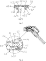
FIG. 2 is a partially exploded diagram of a charging gun according to the present disclosure; -
FIG. 3 is an exploded perspective diagram of a charging gun according to the present disclosure; -
FIG. 4 is a perspective diagram of a circuit module of a charging gun according to the present disclosure; -
FIG. 5 is a perspective diagram of a latching member of a charging gun according to the present disclosure; -
FIG. 6 is a perspective diagram of a waterproof and air-permeable assembly of a charging gun according to the present disclosure; -
FIG. 7 is a cross-sectional diagram of a waterproof and air-permeable assembly of a charging gun according to the present disclosure; and -
FIG. 8 is a cross-sectional diagram of a charging gun according to the present disclosure and a partially enlarged diagram thereof. - In order to make the object, technical solutions and advantages of the present disclosure clearer, the technical solutions of the present disclosure will be clearly and completely described below with reference to the specific embodiments of the present disclosure and the corresponding drawings. It should be clear that the described embodiments are merely part of the embodiments of the present disclosure rather than all of the embodiments. All other embodiments obtained by those skilled in the art without paying creative labor shall fall into the protection scope of the present disclosure.
- Referring to
FIG. 1 to FIG. 3 , a charging gun according to the present disclosure includes ahousing 10 provided with areceiving cavity 12, aplug member 30 inserted into a front end of thereceiving cavity 12, acable assembly 40 inserted into a rear end of thereceiving cavity 12, alatching member 20 movably assembled on the top of thehousing 10, acircuit module 50 mounted in thereceiving cavity 12 and a waterproof and air-permeable assembly 60. - The
housing 10 includes anouter case 11, amounting recess 13 provided at the top of theouter case 11, and a hand-heldmember 14 provided at one side of the outer case. The outer case includes afront end portion 111 and arear end portion 112, and thefront end portion 111 and therear end portion 112 that include an obtuse angle therebetween. The hand-heldmember 14 is provided on an outer side of therear end portion 112. Themounting recess 13 extends from a front end edge of thefront end portion 111 to above the hand-heldmember 14. Thelatching member 20 and the waterproof and air-permeable assembly 60 are mounted in themounting recess 13. Arotation shaft 131 is provided in the middle of themounting recess 13. Amounting hole 132 communicating with thereceiving cavity 12 and arecessed portion 133 that does not communicate with the receivingcavity 12 are provided in a bottom surface of themounting recess 13 located on a front end of therotation shaft 131. Astep portion 134 is provided at a periphery of an upper end surface of themounting hole 132 . - The
cable assembly 40 is inserted from therear end portion 112 of thehousing 10 and includes acable 41 and a number of plug-connection terminals 42 connected to thecable 41. The plug-connection terminal 42 extends into theplug member 30 to interface with a charging receptacle (not shown). Theplug member 30 is inserted from thefront end portion 111 of thehousing 10 and assembled thereto. - Referring to
FIG. 5 , thelatching member 20 is mounted in themounting recess 13. Thelatching member 20 includes apivot hole 21 corresponding to therotation shaft 131, alatching portion 22 extending forwardly from thepivot hole 21 to theplug member 30, apressing portion 23 extending backwardly from thepivot hole 21 to above the hand-heldmember 14, and amagnetic element 24 provided between thelatching portion 22 and thepivot hole 21. Themagnetic element 24 and thelatching member 20 are formed into one piece, or themagnetic element 24 is fixed on thelatching member 20, and themagnetic element 24 can be a magnet. Themagnetic element 24 corresponds to a position of the recessedportion 133 of the mountingrecess 13. The latchingmember 20 achieves rotation within a certain distance by using the cooperation of thepivot hole 21 and therotation shaft 131 as a fulcrum. - Referring to
FIG. 4 , thecircuit module 50 includes a printedcircuit board 51, a number ofconnectors 52 mounted on the printedcircuit board 51, a number ofresistors 54, and amagnetic switch 53. Thecircuit module 51 is mounted in the receivingcavity 12 at a position corresponding to themagnetic element 24. - Referring to
FIGs. 6 and7 , the waterproof and air-permeable assembly 60 includes anupper cover 61, alower cover 62 locked with theupper cover 61, awaterproof ring 63, and a waterproof and air-permeable membrane 64. Theupper cover 61 includes acover face body 613, a number offirst hooks 611 formed by extending downwardly from thecover face body 613, and agap 612 formed between the first hooks 611. Thelower cover 62 includes ahead portion 621, and anelastic locking portion 622 formed by extending downwardly from thehead portion 621 and having an outer diameter smaller than that of thehead portion 621. Afirst locking stand 624 is provided at a periphery of thehead portion 621 for locking with the first hooks 611. Theelastic locking portion 622 includes a number of elastic tab structures. Asecond hook 623 is provided at the periphery of each elastic tab structure to lock at the bottom edge of the mountinghole 132 of the mountingrecess 13. Thewaterproof ring 63 is sleeved at a joint of theelastic locking portion 622 and thehead portion 621 and is clamped at thestep portion 134 on the upper edge of the mountinghole 132 to prevent water from infiltrating. Thelower cover 62 is provided with anair hole 625 penetrating through thehead portion 621 and theelastic locking portion 622 in the up and down direction. The head portion of thelower cover 62 wraps the waterproof and air-permeable membrane 64 at the position of theair hole 625. The waterproof and air-permeable membrane 64 can block passage of water molecules but can allow gas to pass through. Anair chamber 65 is formed between the waterproof and air-permeable membrane 64 and a lower surface of thecover face body 613 of theupper cover 61. Theair chamber 65 exchanges gas and heat with outside through thegap 612 at the periphery of theupper cover 61. Namely, theair chamber 65 is in communication with thegap 612. The waterproof and air-permeable membrane 64 is located below thecover face body 613, so as to prevent dust from directly entering the waterproof and air-permeable membrane 64, which would otherwise cause a decrease in the product performance. - Referring to
FIG. 8 , the waterproof and air-permeable assembly 60 provides a dissipation channel for the heat in the receivingcavity 12 to lower the temperature within the receivingcavity 12, while being locked in the mountinghole 132 to achieve waterproof performance. Themagnetic switch 53 is provided on thecircuit module 50, and themagnetic element 24 corresponding to themagnetic switch 53 is provided on the latchingmember 20. When the latchingmember 20 is pressed to rotate the latchingmember 20 about therotation shaft 131, themagnetic member 24 moves with the latchingmember 20, so that a distance between themagnetic member 24 and themagnetic switch 53 in the receivingcavity 12 is changed, thereby achieving a switch function. The use of such a non-physical contact switch can reduce the design difficulty of waterproofing in the receivingcavity 12 and improve the waterproof performance. - It should also be noted that the terms "including", "comprising", or any other variations thereof are intended to encompass a non-exclusive inclusion, such that the process, method, commodity, or device that include a series of elements include not only those elements, but also includes other elements that are not explicitly listed, or also include elements that are inherent to such a process, method, commodity, or device. In the absence of more restrictions, the elements defined by the statement "including one..." do not exclude cases in which there are additional identical elements in the process, method, commodity, or device that include the described elements.
- The above description is only an embodiment of the present disclosure and is not intended to limit the present disclosure. Various changes and modifications can be made to the present disclosure by those skilled in the art. Any modifications, equivalents, improvements and the like made within the scope of the present disclosure are intended to be included within the scope of the appended claims.
Claims (20)
- A charging gun, comprising:a housing provided with a receiving cavity;a plug member inserted into a front end of the receiving cavity;a cable assembly inserted into a rear end of the receiving cavity;a latching member movably assembled at a periphery of the housing;a circuit module mounted in the receiving cavity; anda waterproof and air-permeable assembly,wherein the circuit module is provided with a magnetic switch, a mounting recess into which the latching member is mounted is provided at the periphery of the housing, the latching member is rotatable about a rotation shaft in the mounting recess, the latching member is provided with a magnetic element, a state of the magnetic switch is controlled by a change of a relative distance between the magnetic element and the magnetic switch with rotation of the latching member, a mounting hole communicating with the receiving cavity is provided in a bottom surface of the mounting recess, and the waterproof and air-permeable assembly is mounted in the mounting hole to discharge heat in the receiving cavity.
- The charging gun according to claim 1, wherein the housing comprises an outer case and a hand-held member provided on one side of the outer case, the outer case comprises a front end portion and a rear end portion that comprise an obtuse angle therebetween, the mounting recess extends from a front end edge of the front end portion to above the hand-held member, and the rotation shaft is provided in the mounting recess.
- The charging gun according to claim 2, wherein the latching member comprises a pivot hole corresponding to the rotation shaft, a latching portion extending forwardly from the pivot hole to the plug member, and a pressing portion extending backwardly from the pivot hole to above the hand-held member, the magnetic element is provided between the latching portion and the pivot hole, and the latching member achieves rotation within a certain distance by using cooperation of the pivot hole and the rotation shaft as a fulcrum.
- The charging gun according to claim 3, wherein the magnetic member and the latching member are formed into one piece or the magnetic member is mounted on the latching member, and the magnetic element is a magnet.
- The charging gun according to claim 3, wherein a recessed portion is provided at a position of the mounting recess corresponding to the magnetic element, and the circuit module is provided in the receiving cavity below the recessed portion.
- The charging gun according to claim 1, wherein a step portion is provided on a periphery of an upper end surface of the mounting hole.
- The charging gun according to claim 6, wherein the waterproof and air-permeable assembly comprises an upper cover, a lower cover locked with the upper cover into one piece, a waterproof ring sleeved on a periphery of the lower cover and clamped at the step portion, and a waterproof and air-permeable membrane positioned on a top of the lower cover, the lower cover comprises a head portion and an elastic locking portion formed by extending downwardly from the head portion and inserted into the mounting hole, and the lower cover is up and down connected to form an air hole.
- The charging gun according to claim 7, wherein the upper cover comprises a cover face body, a number of first hooks formed by extending downwardly from the cover face body, and a gap formed between the number of first hooks, the waterproof and air-permeable membrane covers the air hole of the head portion, an air chamber is formed between the cover face body and the waterproof and air-permeable membrane, and the air chamber is in communication with outside through the gap.
- The charging gun according to claim 8, wherein a first locking stand for locking with the number of first hooks is provided at the periphery of the head portion, the elastic locking portion comprises a number of elastic tab structures, a second hook is provided at a periphery of each of the number of elastic tab structures to lock at a bottom edge of the mounting hole of the mounting recess.
- The charging gun according to claim 2, wherein the cable assembly is inserted from the rear end portion of the housing, the cable assembly comprises a cable and a number of plug-connection terminals connected to the cable, the number of plug-connection terminals extend into the plug member to interface with a charging receptacle, and the plug member is inserted from the front end portion of the housing and assembled thereto.
- A charging gun, comprising:a housing provided with a receiving cavity;a plug member inserted into a front end of the receiving cavity;a cable assembly inserted into a rear end of the receiving cavity;a latching member movably assembled at a periphery of the housing; anda circuit module mounted in the receiving cavity,wherein the circuit module is provided with a magnetic switch, a mounting recess into which the latching member is mounted is provided at the periphery of the housing, the latching member is rotatable about a rotation shaft in the mounting recess, the latching member is provided with a magnetic element, and a state of the magnetic switch is controlled by a change of a relative distance between the magnetic element and the magnetic switch with rotation of the latching member.
- The charging gun according to claim 11, wherein the housing comprises an outer case and a hand-held member provided on one side of the outer case, the outer case comprises a front end portion and a rear end portion that comprise an obtuse angle therebetween, the mounting recess extends from a front end edge of the front end portion to above the hand-held member, and the rotation shaft is provided in the mounting recess.
- The charging gun according to claim 12, wherein the latching member comprises a pivot hole corresponding to the rotation shaft, a latching portion extending forwardly from the pivot hole to the plug member, and a pressing portion extending backwardly from the pivot hole to above the hand-held member.
- The charging gun according to claim 13, wherein the magnetic element is provided between the latching portion and the pivot hole, and the latching member achieves rotation within a certain distance by using cooperation of the pivot hole and the rotation shaft as a fulcrum.
- The charging gun according to claim 14, wherein the magnetic member and the latching member are formed into one piece or the magnetic member is mounted on the latching member, and the magnetic member is a magnet.
- The charging gun according to claim 12, wherein a recessed portion is provided at a position of the mounting recess corresponding to the magnetic element, and the circuit module is provided in the receiving cavity below the recessed portion.
- The charging gun according to claim 11, wherein the cable assembly is inserted from the rear end portion of the housing, the cable assembly comprises a cable and a number of plug-connection terminals connected to the cable, the number of plug-connection terminals extend into the plug member to interface with a charging receptacle, and the plug member is inserted from the front end portion of the housing and assembled thereto.
- The charging gun according to claim 11, wherein the circuit module comprises a printed circuit board, a number of connectors and a number of resistors that are mounted on the printed circuit board, and the magnetic switch is mounted on the printed circuit board.
- The charging gun according to claim 12, wherein a mounting hole communicating with the receiving cavity is provided in a bottom surface of the mounting recess, a step portion is provided on a periphery of an upper end surface of the mounting hole, and a waterproof and air-permeable assembly is locked in the mounting hole to discharge heat in the receiving cavity.
- The charging gun according to claim 17, wherein the waterproof and air-permeable assembly comprises an upper cover, a lower cover locked with the upper cover to be formed into one piece, a waterproof ring sleeved on a periphery of the lower cover and clamped at the step portion, and a waterproof and air-permeable membrane positioned on a top of the lower cover, the lower cover comprises a head portion and an elastic locking portion formed by extending downwardly from the head portion and inserted into the mounting hole, the lower cover is up and down connected to form an air hole, and the air hole exchanges heat with outside through the waterproof and air-permeable membrane.
Applications Claiming Priority (3)
| Application Number | Priority Date | Filing Date | Title |
|---|---|---|---|
| CN201710171691.5A CN106887751B (en) | 2017-03-21 | 2017-03-21 | Charging gun |
| CN201710171693.4A CN106848731B (en) | 2017-03-21 | 2017-03-21 | Charging gun |
| PCT/CN2018/075897 WO2018171358A1 (en) | 2017-03-21 | 2018-02-09 | Charging gun |
Publications (2)
| Publication Number | Publication Date |
|---|---|
| EP3605744A1 true EP3605744A1 (en) | 2020-02-05 |
| EP3605744A4 EP3605744A4 (en) | 2020-12-09 |
Family
ID=63586108
Family Applications (1)
| Application Number | Title | Priority Date | Filing Date |
|---|---|---|---|
| EP18772490.1A Pending EP3605744A4 (en) | 2017-03-21 | 2018-02-09 | LOADING GUN |
Country Status (3)
| Country | Link |
|---|---|
| US (1) | US10770828B2 (en) |
| EP (1) | EP3605744A4 (en) |
| WO (1) | WO2018171358A1 (en) |
Cited By (1)
| Publication number | Priority date | Publication date | Assignee | Title |
|---|---|---|---|---|
| WO2022175286A1 (en) * | 2021-02-16 | 2022-08-25 | Fraunhofer-Gesellschaft zur Förderung der angewandten Forschung e.V. | Electric contact unit |
Families Citing this family (21)
| Publication number | Priority date | Publication date | Assignee | Title |
|---|---|---|---|---|
| DE102018100831A1 (en) * | 2018-01-16 | 2019-07-18 | Dr. Ing. H.C. F. Porsche Aktiengesellschaft | Charging plug for electric cars and its manufacture |
| CN109367415A (en) * | 2018-11-30 | 2019-02-22 | 威海市泓淋电力技术股份有限公司 | A safety plug connector for a DC charging gun |
| CN110126654B (en) * | 2019-05-22 | 2022-11-11 | 安徽省智慧交通科技有限责任公司 | Charging device for new energy automobile |
| US11858374B1 (en) * | 2020-02-07 | 2024-01-02 | John Tyler Polasek | Vehicular motion energy transfer system |
| CN112572182A (en) * | 2020-12-25 | 2021-03-30 | 威海市泓淋电力技术股份有限公司 | Integrated charging gun of IP68 protection grade |
| CN112909667A (en) * | 2021-03-03 | 2021-06-04 | 蔚来汽车科技(安徽)有限公司 | Charging gun |
| USD998571S1 (en) * | 2021-10-27 | 2023-09-12 | Ti-Lane Precision Electronic Co., Ltd. | Vehicle charging connector |
| US11757229B2 (en) * | 2021-11-11 | 2023-09-12 | Onanon, Inc. | Electromagnetic Electrical Connector System |
| JP7811350B2 (en) * | 2021-12-22 | 2026-02-05 | 日本航空電子工業株式会社 | Charging connector |
| TWD220018S (en) * | 2021-12-24 | 2022-07-11 | 華新麗華股份有限公司 | Connector plug |
| CN114506233B (en) * | 2022-04-19 | 2022-06-24 | 江苏淮海新能源车辆有限公司 | A rifle that charges for new energy automobile |
| KR20250068715A (en) * | 2022-09-12 | 2025-05-16 | 볼트포스트, 인크. | Charger handle for electric vehicle charging |
| CN115723598A (en) * | 2022-12-08 | 2023-03-03 | 浦江漱金电子科技有限公司 | New energy automobile fills electric pile |
| USD1071843S1 (en) * | 2023-03-23 | 2025-04-22 | Luxshare Precision Industry Company Limited | Charging connector for electric vehicles |
| USD1079618S1 (en) * | 2023-07-28 | 2025-06-17 | Guangdong Chongwei technology Co., LTD | Charging gun |
| USD1080552S1 (en) * | 2023-08-27 | 2025-06-24 | Suzhou Juying New Energy Vehicle Connection System Co., Ltd. | Electrical vehicle charging adaptor |
| CN117301902B (en) * | 2023-10-16 | 2024-03-26 | 苏州联充新能源科技有限公司 | New energy vehicle rifle that charges that security is high |
| USD1098006S1 (en) * | 2023-11-07 | 2025-10-14 | Juntao Hu | Electric vehicle charger plug |
| USD1112052S1 (en) * | 2024-01-03 | 2026-02-10 | Guangdong Chongwei technology Co., LTD | Charging pile |
| CN119160013B (en) * | 2024-09-13 | 2025-05-02 | 深圳市一航电动科技有限公司 | Charging gun |
| CN118867753B (en) * | 2024-09-23 | 2024-11-22 | 上海铂铭行汽车有限公司 | An emergency self-extraction device for a car charging gun |
Family Cites Families (13)
| Publication number | Priority date | Publication date | Assignee | Title |
|---|---|---|---|---|
| JP4672530B2 (en) * | 2005-11-17 | 2011-04-20 | 日東電工株式会社 | Ventilation member |
| US8016607B2 (en) * | 2010-01-08 | 2011-09-13 | Lear Corporation | Connector assembly for electric vehicle charging |
| JP5197699B2 (en) * | 2010-09-09 | 2013-05-15 | 住友電装株式会社 | Charging connector |
| US20120126747A1 (en) * | 2010-11-19 | 2012-05-24 | Delphi Technologies, Inc. | Battery charger having non-contact electrical switch |
| DE102011002024A1 (en) * | 2011-04-13 | 2012-10-18 | Tyco Electronics Amp Gmbh | Charging plug with contactless switching device |
| KR20170013888A (en) * | 2014-05-28 | 2017-02-07 | 닛토덴코 가부시키가이샤 | Metal case and ventilation structure using same |
| JP2016201319A (en) * | 2015-04-14 | 2016-12-01 | 住友電装株式会社 | Waterproof connector |
| JP6072947B1 (en) * | 2016-02-01 | 2017-02-01 | 三菱電機株式会社 | Waterproof control device |
| CN205960320U (en) * | 2016-07-08 | 2017-02-15 | 泰科电子(上海)有限公司 | Charging plug and fill electric pile including this charging plug |
| CN106229770B (en) * | 2016-08-30 | 2019-04-19 | 张家港友诚新能源科技股份有限公司 | A locking and unlocking device for a charging plug |
| CN106887751B (en) * | 2017-03-21 | 2019-03-29 | 昆山惠禾新能源科技有限公司 | Charging gun |
| CN207234031U (en) * | 2017-03-21 | 2018-04-13 | 昆山惠禾新能源科技有限公司 | Charging gun |
| CN106848731B (en) * | 2017-03-21 | 2019-04-23 | 昆山惠禾新能源科技有限公司 | Charging gun |
-
2018
- 2018-02-09 EP EP18772490.1A patent/EP3605744A4/en active Pending
- 2018-02-09 WO PCT/CN2018/075897 patent/WO2018171358A1/en not_active Ceased
-
2019
- 2019-09-23 US US16/579,005 patent/US10770828B2/en active Active
Cited By (2)
| Publication number | Priority date | Publication date | Assignee | Title |
|---|---|---|---|---|
| WO2022175286A1 (en) * | 2021-02-16 | 2022-08-25 | Fraunhofer-Gesellschaft zur Förderung der angewandten Forschung e.V. | Electric contact unit |
| JP2024508729A (en) * | 2021-02-16 | 2024-02-28 | フラウンホッファー-ゲゼルシャフト ツァー フェーデルング デア アンゲバンテン フォルシュング エー ファー | electrical contact unit |
Also Published As
| Publication number | Publication date |
|---|---|
| US20200021056A1 (en) | 2020-01-16 |
| WO2018171358A1 (en) | 2018-09-27 |
| US10770828B2 (en) | 2020-09-08 |
| EP3605744A4 (en) | 2020-12-09 |
Similar Documents
| Publication | Publication Date | Title |
|---|---|---|
| EP3605744A1 (en) | Charging gun | |
| CN106887751B (en) | Charging gun | |
| US6447303B1 (en) | Communication module connector | |
| US7715179B2 (en) | Power supply for a computer device | |
| US20150180169A1 (en) | Connector assembly with improved locking structures | |
| CN106848731B (en) | Charging gun | |
| EP4181324A1 (en) | Connector assembly and waterproof cap | |
| JP2020077629A (en) | Multifunctional high-voltage connector and battery products | |
| US20060230296A1 (en) | Controller housing with connector retention assembly and method | |
| CN103178392B (en) | Cable-assembly | |
| CN112466699B (en) | Knob structure and electronic equipment | |
| CN102487591A (en) | mobile terminal | |
| CN207234031U (en) | Charging gun | |
| US20080064246A1 (en) | Electrical connector | |
| CN215911661U (en) | a screener | |
| CN216015921U (en) | Wall power socket with USB charging device based on sink type slot | |
| CN214706379U (en) | Socket shutter structure | |
| CN207069214U (en) | USB data line | |
| CN201594613U (en) | electrical connector | |
| CN223829414U (en) | Charging box and earphone system | |
| CN217405803U (en) | Waterproof camera elbow female connector | |
| CN215379476U (en) | Input panel assembly and charging panel assembly | |
| CN221575619U (en) | 4G wireless network card | |
| US20070099471A1 (en) | Electronic device assembly | |
| CN223598630U (en) | contactor |
Legal Events
| Date | Code | Title | Description |
|---|---|---|---|
| STAA | Information on the status of an ep patent application or granted ep patent |
Free format text: STATUS: THE INTERNATIONAL PUBLICATION HAS BEEN MADE |
|
| PUAI | Public reference made under article 153(3) epc to a published international application that has entered the european phase |
Free format text: ORIGINAL CODE: 0009012 |
|
| STAA | Information on the status of an ep patent application or granted ep patent |
Free format text: STATUS: REQUEST FOR EXAMINATION WAS MADE |
|
| 17P | Request for examination filed |
Effective date: 20191004 |
|
| AK | Designated contracting states |
Kind code of ref document: A1 Designated state(s): AL AT BE BG CH CY CZ DE DK EE ES FI FR GB GR HR HU IE IS IT LI LT LU LV MC MK MT NL NO PL PT RO RS SE SI SK SM TR |
|
| AX | Request for extension of the european patent |
Extension state: BA ME |
|
| DAV | Request for validation of the european patent (deleted) | ||
| DAX | Request for extension of the european patent (deleted) | ||
| A4 | Supplementary search report drawn up and despatched |
Effective date: 20201110 |
|
| RIC1 | Information provided on ipc code assigned before grant |
Ipc: H01R 13/66 20060101ALI20201104BHEP Ipc: H01R 13/52 20060101AFI20201104BHEP Ipc: H01R 13/703 20060101ALI20201104BHEP Ipc: H01R 13/533 20060101ALI20201104BHEP Ipc: H05K 5/02 20060101ALN20201104BHEP Ipc: H01R 13/627 20060101ALI20201104BHEP Ipc: B65D 77/22 20060101ALI20201104BHEP Ipc: B60L 53/16 20190101ALI20201104BHEP |
|
| STAA | Information on the status of an ep patent application or granted ep patent |
Free format text: STATUS: EXAMINATION IS IN PROGRESS |
|
| 17Q | First examination report despatched |
Effective date: 20220303 |
|
| RAP1 | Party data changed (applicant data changed or rights of an application transferred) |
Owner name: SHENZHEN EVERWIN PRECISION TECHNOLOGY CO., LTD. |