EP3605719A1 - Battery module - Google Patents
Battery module Download PDFInfo
- Publication number
- EP3605719A1 EP3605719A1 EP18874537.6A EP18874537A EP3605719A1 EP 3605719 A1 EP3605719 A1 EP 3605719A1 EP 18874537 A EP18874537 A EP 18874537A EP 3605719 A1 EP3605719 A1 EP 3605719A1
- Authority
- EP
- European Patent Office
- Prior art keywords
- circuit board
- printed circuit
- flexible printed
- battery
- battery cell
- Prior art date
- Legal status (The legal status is an assumption and is not a legal conclusion. Google has not performed a legal analysis and makes no representation as to the accuracy of the status listed.)
- Granted
Links
Images


Classifications
-
- H—ELECTRICITY
- H01—ELECTRIC ELEMENTS
- H01M—PROCESSES OR MEANS, e.g. BATTERIES, FOR THE DIRECT CONVERSION OF CHEMICAL ENERGY INTO ELECTRICAL ENERGY
- H01M10/00—Secondary cells; Manufacture thereof
- H01M10/42—Methods or arrangements for servicing or maintenance of secondary cells or secondary half-cells
- H01M10/425—Structural combination with electronic components, e.g. electronic circuits integrated to the outside of the casing
- H01M10/4257—Smart batteries, e.g. electronic circuits inside the housing of the cells or batteries
-
- H—ELECTRICITY
- H01—ELECTRIC ELEMENTS
- H01M—PROCESSES OR MEANS, e.g. BATTERIES, FOR THE DIRECT CONVERSION OF CHEMICAL ENERGY INTO ELECTRICAL ENERGY
- H01M10/00—Secondary cells; Manufacture thereof
- H01M10/42—Methods or arrangements for servicing or maintenance of secondary cells or secondary half-cells
- H01M10/48—Accumulators combined with arrangements for measuring, testing or indicating the condition of cells, e.g. the level or density of the electrolyte
- H01M10/486—Accumulators combined with arrangements for measuring, testing or indicating the condition of cells, e.g. the level or density of the electrolyte for measuring temperature
-
- G—PHYSICS
- G01—MEASURING; TESTING
- G01R—MEASURING ELECTRIC VARIABLES; MEASURING MAGNETIC VARIABLES
- G01R31/00—Arrangements for testing electric properties; Arrangements for locating electric faults; Arrangements for electrical testing characterised by what is being tested not provided for elsewhere
- G01R31/36—Arrangements for testing, measuring or monitoring the electrical condition of accumulators or electric batteries, e.g. capacity or state of charge [SoC]
-
- H—ELECTRICITY
- H01—ELECTRIC ELEMENTS
- H01M—PROCESSES OR MEANS, e.g. BATTERIES, FOR THE DIRECT CONVERSION OF CHEMICAL ENERGY INTO ELECTRICAL ENERGY
- H01M10/00—Secondary cells; Manufacture thereof
- H01M10/42—Methods or arrangements for servicing or maintenance of secondary cells or secondary half-cells
- H01M10/425—Structural combination with electronic components, e.g. electronic circuits integrated to the outside of the casing
-
- H—ELECTRICITY
- H01—ELECTRIC ELEMENTS
- H01M—PROCESSES OR MEANS, e.g. BATTERIES, FOR THE DIRECT CONVERSION OF CHEMICAL ENERGY INTO ELECTRICAL ENERGY
- H01M50/00—Constructional details or processes of manufacture of the non-active parts of electrochemical cells other than fuel cells, e.g. hybrid cells
- H01M50/20—Mountings; Secondary casings or frames; Racks, modules or packs; Suspension devices; Shock absorbers; Transport or carrying devices; Holders
-
- H—ELECTRICITY
- H01—ELECTRIC ELEMENTS
- H01M—PROCESSES OR MEANS, e.g. BATTERIES, FOR THE DIRECT CONVERSION OF CHEMICAL ENERGY INTO ELECTRICAL ENERGY
- H01M10/00—Secondary cells; Manufacture thereof
- H01M10/42—Methods or arrangements for servicing or maintenance of secondary cells or secondary half-cells
- H01M10/425—Structural combination with electronic components, e.g. electronic circuits integrated to the outside of the casing
- H01M2010/4271—Battery management systems including electronic circuits, e.g. control of current or voltage to keep battery in healthy state, cell balancing
-
- H—ELECTRICITY
- H01—ELECTRIC ELEMENTS
- H01M—PROCESSES OR MEANS, e.g. BATTERIES, FOR THE DIRECT CONVERSION OF CHEMICAL ENERGY INTO ELECTRICAL ENERGY
- H01M2200/00—Safety devices for primary or secondary batteries
- H01M2200/10—Temperature sensitive devices
-
- H—ELECTRICITY
- H01—ELECTRIC ELEMENTS
- H01M—PROCESSES OR MEANS, e.g. BATTERIES, FOR THE DIRECT CONVERSION OF CHEMICAL ENERGY INTO ELECTRICAL ENERGY
- H01M50/00—Constructional details or processes of manufacture of the non-active parts of electrochemical cells other than fuel cells, e.g. hybrid cells
- H01M50/20—Mountings; Secondary casings or frames; Racks, modules or packs; Suspension devices; Shock absorbers; Transport or carrying devices; Holders
- H01M50/204—Racks, modules or packs for multiple batteries or multiple cells
- H01M50/207—Racks, modules or packs for multiple batteries or multiple cells characterised by their shape
- H01M50/209—Racks, modules or packs for multiple batteries or multiple cells characterised by their shape adapted for prismatic or rectangular cells
-
- Y—GENERAL TAGGING OF NEW TECHNOLOGICAL DEVELOPMENTS; GENERAL TAGGING OF CROSS-SECTIONAL TECHNOLOGIES SPANNING OVER SEVERAL SECTIONS OF THE IPC; TECHNICAL SUBJECTS COVERED BY FORMER USPC CROSS-REFERENCE ART COLLECTIONS [XRACs] AND DIGESTS
- Y02—TECHNOLOGIES OR APPLICATIONS FOR MITIGATION OR ADAPTATION AGAINST CLIMATE CHANGE
- Y02E—REDUCTION OF GREENHOUSE GAS [GHG] EMISSIONS, RELATED TO ENERGY GENERATION, TRANSMISSION OR DISTRIBUTION
- Y02E60/00—Enabling technologies; Technologies with a potential or indirect contribution to GHG emissions mitigation
- Y02E60/10—Energy storage using batteries
Definitions
- the present invention relates to a battery module, and more particularly, it relates to a battery module that includes an upper plate having an elastic member.
- the rechargeable battery can be classified into a cylindrical rechargeable battery, a prismatic rechargeable battery, and a pouch-type rechargeable battery depending on the shape, and in terms of materials, there is a high demand for a lithium rechargeable battery as a lithium ion battery and a lithium ion polymer battery having high energy density and high discharge voltage as well as and output stability.
- the rechargeable battery continuously repeats charging and discharging, and through such a process, a large amount of heat is generated and an output voltage state of the battery may be changed.
- a temperature increase and an output voltage change due to the heat generation cause malfunctioning of an element that uses the corresponding battery, deteriorates operation efficiency, and shortens a life-span of the battery.
- a battery pack since a battery pack includes a battery module structure in which a plurality of battery cells are embedded in a pack case, a problem may occur in safety and operation efficiency of the battery pack when over-voltage, over-current, and over-heating occur in some of the battery cells. Accordingly, a temperature sensor and the like is connected to the battery cells to control the battery cells while determining an operation state of the battery cell in real time or at regular intervals. However, a temperature measurement error may occur depending on the degree of contact of the temperature sensor with the battery cell.
- Exemplary embodiments of the present invention have been made in an effort to provide a battery module in which a force is applied toward a direction of a battery cell and thus a temperature sensor stably contacts the battery cell, thereby increasing accuracy in measurement of a battery cell temperature.
- a battery module including a temperature sensor includes: a flexible printed circuit board where the temperature sensor is provided; a battery cell that overlaps a portion of the flexible printed circuit board, in which the temperature sensor is provided; and an upper plate that is disposed above the flexible printed circuit board, wherein the upper plate is partially cut and thus an elastic member is formed, and the elastic member presses the portion of the flexible printed circuit board in which the temperature sensor is provided and thus the battery cell and the flexible printed circuit board contact each other.
- the battery module may include a compression pad that is disposed between a compression pad that is disposed between the upper plate and the flexible printed circuit board.
- the battery module may further include: a first adhesive layer that is disposed between the compression pad and the upper plate; and a second adhesive layer that is disposed between the compression pad and the flexible printed circuit board.
- the first adhesive layer and the second adhesive may be respectively provided as a double-sided adhesive tape.
- a force is applied in a direction toward the battery cell by an elastic force of the elastic member such that the temperature sensor and the battery cell may maintain a contact state.
- the temperature sensor may be a thermistor.
- a gap between the elastic member and the battery may be smaller than a gap between the upper plate and the battery cell.
- the battery cell may be provided in plural and a lamination direction of the plurality of battery cells may be parallel with a top surface of the upper plate, and the flexible printed circuit board may contact a side surface of the battery cell.
- the elastic member may be formed in plural in the upper plate, and each elastic member may contact a different battery cell.
- the compression pad may be formed of polyurethane foam.
- a battery module in which the temperature sensor is stably attached to a battery cell by applying a force toward the battery cell using an elastic member formed on the upper plate can be provided, thereby improving accuracy of temperature measurement of the battery cell.
- the phrase “on a plane” means viewing a target portion from the top
- the phrase “on a cross-section” means viewing a cross-section formed by vertically cutting a target portion from the side.
- FIG. 1 is a schematic perspective view of a battery module according to an exemplary embodiment of the present invention.
- a battery module 1000 includes a battery cell laminate 110, first and second end plates 100a and 100b, an upper plate 200, and a lower plate (not shown).
- the battery cell laminate 110 may be covered by a cell cover 300.
- the upper plate 200 is partially cut such that an elastic member 210 may be formed.
- an elastic member 210 may be provided in plural, and the elastic member 210 may be bent toward the battery cell laminate 110.
- the elastic member 210 according to the present exemplary embodiment will now be described in detail with reference to FIG. 2 to FIG. 4 .
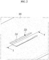
- FIG. 2 is a partially enlarged view of a portion A of FIG. 1 .
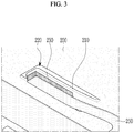
- FIG. 3 schematically shows the inside of the portion A of FIG. 1 .
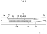
- FIG. 4 is a cross-sectional view of FIG. 2 , taken along the line I-I'.
- the elastic member 210 may be formed by partially cutting the upper plate 200. Specifically, a cutout 220 formed in the shape of " ⁇ " is formed in a part of the upper plate 200, and a portion of the upper plate 200 remaining in a portion surrounded by the cutout 220 becomes the elastic member 210.
- the cutout 220 may be formed in plural in the upper plate 200, and the elastic member 210 is formed in each of the plurality of cutouts 220, and accordingly the elastic member 210 may be provided in plural.
- a flexible printed circuit board 250 is disposed at a lower end of the elastic member 210.
- One end of the flexible printed circuit board 250 extends along a direction in which the elastic member 210 extends, and the elastic member 210 may mostly overlap the flexible printed circuit board 250 in an x-axis direction of FIG. 1 .
- a compression pad 230 is disposed between the elastic member 210 and one end of the flexible printed circuit board 250.
- the compression pad 230 may be formed of polyurethane foam. Since the compression pad 230 is additionally formed, durability of the elastic member 210 can be improved. In addition, even when a side surface portion of the battery cell, which will be described later, is not completely parallel with a top surface of the top plate 200, an area where the flexible printed circuit board 250 and the battery cell contact each other may be increased by a cushion effect of the compression pad 230.
- the compression pad 230 since the compression pad 230 according to the present embodiment formed of a polyurethane foam or the like has dimensional stability, it can be used on a non-flat surface, and the compression pad 230 increases a contact surface or contactability, and has durability, thereby assuring performance with respect to vibration and impact.
- a temperature sensor 260 is installed in the flexible printed circuit board 250 according to the present exemplary embodiment.
- the elastic member 210 presses the portion of the flexible printed circuit board 250, in which the temperature sensor 260 is installed, such that the battery cell 110e and the flexible printed circuit board 250 contact each other. That is, the battery cell 110e and the flexible printed circuit board 250 directly contact each other without disposing any element between the battery cell 110e and the flexible printed circuit board 250, and thus the temperature sensor 260 can accurately measure heat and the like generated from the battery cell 110e.
- the temperature sensor 260 and the battery cell 1102 can be stably maintained in a contact state.
- an adhesive layer 240 may be formed in each of an upper surface and a lower surface of the compression pad 230.
- a first adhesive layer 240a may be disposed between the compression pad 230 and the elastic member 210, and a second adhesive layer 240b may be disposed between the compression pad 230 and the flexible printed circuit board 250.
- the first adhesive layer 240a and the second adhesive layer 240b may be provided as a double-sided adhesive tape.
- the flexible printed circuit board 250 can be combined to the elastic member 210 by using such a double-sided adhesive tape.
- a gap between the elastic member 210 and the battery cell 110e is smaller than a gap between the upper plate 200 and the battery cell 110e.
- the temperature sensor 260 may be implemented by using a thermistor.
- the thermistor is a semiconductor with resistance that changes in response to a temperature, and may be formed by mixing and sintering an oxide such as copper, manganese, nickel, cobalt, chromium, iron, and the like. Such a thermistor is advantageous in that it is small in size and can measure a fast temperature change and a fine temperature change.
- Temperature information measured by the temperature sensor 260 can be transmitted to other devices outside of the battery module.
- the measured temperature information is transmitted to a battery management system (BMS) outside of the battery module and thus may be used to control the battery module.
- BMS battery management system
- the battery module may include a cable for temperature measurement (not show) of which one end is connected to the temperature sensor 260.
- a connector may be provided at the other end of the cable, and the connector may be connected with an external device such as the BMS.
- FIG. 5 is a perspective view of a plurality of battery cell arrays exposed by partially exposing the upper plate in FIG. 1 .
- the battery cell laminate 110 of FIG. 1 includes a plurality of battery cells 110a and 110b, and a direction in which the plurality of battery cells 110a and 110b are arranged may be an X-direction that is parallel with the top surface of the upper plate 200.
- the battery cells 110a and 110b may each be formed in the shape of a rectangle having a length in a Y-axis direction and a width in a Z-axis direction.
- each of the two elastic members 210a and 210b may press the flexible printed circuit board that contacts a side surface of another battery cell.
Landscapes
- Engineering & Computer Science (AREA)
- Chemical & Material Sciences (AREA)
- Chemical Kinetics & Catalysis (AREA)
- Electrochemistry (AREA)
- General Chemical & Material Sciences (AREA)
- Manufacturing & Machinery (AREA)
- Microelectronics & Electronic Packaging (AREA)
- Physics & Mathematics (AREA)
- General Physics & Mathematics (AREA)
- Battery Mounting, Suspending (AREA)
- Secondary Cells (AREA)
Abstract
Description
- This application claims priority to and the benefit of Korean Patent Application No.
10-2017-0146776 - The present invention relates to a battery module, and more particularly, it relates to a battery module that includes an upper plate having an elastic member.
- Recently, as technology development of and demand for mobile devices grow, demand for a rechargeable battery as an energy source has been rapidly increased. Accordingly, various researches and studies with respect to a rechargeable battery that can fulfill various needs have been carried out.
- The rechargeable battery can be classified into a cylindrical rechargeable battery, a prismatic rechargeable battery, and a pouch-type rechargeable battery depending on the shape, and in terms of materials, there is a high demand for a lithium rechargeable battery as a lithium ion battery and a lithium ion polymer battery having high energy density and high discharge voltage as well as and output stability.
- The rechargeable battery continuously repeats charging and discharging, and through such a process, a large amount of heat is generated and an output voltage state of the battery may be changed. A temperature increase and an output voltage change due to the heat generation cause malfunctioning of an element that uses the corresponding battery, deteriorates operation efficiency, and shortens a life-span of the battery.
- In addition, since a battery pack includes a battery module structure in which a plurality of battery cells are embedded in a pack case, a problem may occur in safety and operation efficiency of the battery pack when over-voltage, over-current, and over-heating occur in some of the battery cells. Accordingly, a temperature sensor and the like is connected to the battery cells to control the battery cells while determining an operation state of the battery cell in real time or at regular intervals. However, a temperature measurement error may occur depending on the degree of contact of the temperature sensor with the battery cell.
- Exemplary embodiments of the present invention have been made in an effort to provide a battery module in which a force is applied toward a direction of a battery cell and thus a temperature sensor stably contacts the battery cell, thereby increasing accuracy in measurement of a battery cell temperature.
- However, the problems to be solved by the embodiments of the present invention are not limited to the above-mentioned problems, but can be variously extended within the scope of the technical idea included in the present invention.
- A battery module including a temperature sensor according to an exemplary embodiment of the present invention includes: a flexible printed circuit board where the temperature sensor is provided; a battery cell that overlaps a portion of the flexible printed circuit board, in which the temperature sensor is provided; and an upper plate that is disposed above the flexible printed circuit board, wherein the upper plate is partially cut and thus an elastic member is formed, and the elastic member presses the portion of the flexible printed circuit board in which the temperature sensor is provided and thus the battery cell and the flexible printed circuit board contact each other.
- The battery module may include a compression pad that is disposed between a compression pad that is disposed between the upper plate and the flexible printed circuit board.
- The battery module may further include: a first adhesive layer that is disposed between the compression pad and the upper plate; and a second adhesive layer that is disposed between the compression pad and the flexible printed circuit board.
- The first adhesive layer and the second adhesive may be respectively provided as a double-sided adhesive tape.
- A force is applied in a direction toward the battery cell by an elastic force of the elastic member such that the temperature sensor and the battery cell may maintain a contact state.
- The temperature sensor may be a thermistor.
- A gap between the elastic member and the battery may be smaller than a gap between the upper plate and the battery cell.
- The battery cell may be provided in plural and a lamination direction of the plurality of battery cells may be parallel with a top surface of the upper plate, and the flexible printed circuit board may contact a side surface of the battery cell.
- The elastic member may be formed in plural in the upper plate, and each elastic member may contact a different battery cell.
- The compression pad may be formed of polyurethane foam.
- According to the exemplary embodiments, a battery module in which the temperature sensor is stably attached to a battery cell by applying a force toward the battery cell using an elastic member formed on the upper plate can be provided, thereby improving accuracy of temperature measurement of the battery cell.
-
-
FIG. 1 is a schematic perspective view of a battery module according to an exemplary embodiment of the present invention. -
FIG. 2 is a partially enlarged view of a portion "A" inFIG. 1 . -
FIG. 3 is a partial schematic view of the inside of the portion "A" ofFIG. 1 . -
FIG. 4 is a cross-sectional view ofFIG. 2 , taken along the line I-I'. -
FIG. 5 is a perspective view of an array of a plurality of battery cells by exposing the upper plate inFIG. 1 . - The present invention will be described more fully hereinafter with reference to the accompanying drawings, in which exemplary embodiments of the invention are shown. As those skilled in the art would realize, the described embodiments may be modified in various different ways, all without departing from the spirit or scope of the present invention.
- The drawings and description are to be regarded as illustrative in nature and not restrictive. Like reference numerals designate like elements throughout the specification.
- Further, in the drawings, size and thickness of each element are arbitrarily represented for better understanding and ease of description, but the present invention is not limited thereto. In the drawings, the thickness of layers, films, panels, regions, etc., are exaggerated for clarity. In addition, for convenience of description and better understanding, the thickness of some of layers and regions is exaggerated in the drawings.
- It will be understood that when an element such as a layer, film, region, or substrate is referred to as being "on" another element, it can be directly on the other element or intervening elements may also be present. In contrast, when an element is referred to as being "directly on" another element, there are no intervening elements present. The word "on" or "above" means positioned on or below the object portion, and does not necessarily mean positioned on the upper side of the object portion based on a gravitational direction.
- In addition, unless explicitly described to the contrary, the word "comprise" and variations such as "comprises" or "comprising" will be understood to imply the inclusion of stated elements but not the exclusion of any other elements.
- Further, in this specification, the phrase "on a plane" means viewing a target portion from the top, and the phrase "on a cross-section" means viewing a cross-section formed by vertically cutting a target portion from the side.
-
FIG. 1 is a schematic perspective view of a battery module according to an exemplary embodiment of the present invention. - Referring to
FIG. 1 , abattery module 1000 according to an exemplary embodiment of the present invention includes abattery cell laminate 110, first andsecond end plates upper plate 200, and a lower plate (not shown). Thebattery cell laminate 110 may be covered by acell cover 300. - In the present exemplary embodiment, the
upper plate 200 is partially cut such that anelastic member 210 may be formed. Such anelastic member 210 may be provided in plural, and theelastic member 210 may be bent toward thebattery cell laminate 110. Theelastic member 210 according to the present exemplary embodiment will now be described in detail with reference toFIG. 2 to FIG. 4 . -
FIG. 2 is a partially enlarged view of a portion A ofFIG. 1 .FIG. 3 schematically shows the inside of the portion A ofFIG. 1 .FIG. 4 is a cross-sectional view ofFIG. 2 , taken along the line I-I'. - Referring to
FIG. 1 andFIG. 2 , theelastic member 210 according to the present exemplary embodiment may be formed by partially cutting theupper plate 200. Specifically, acutout 220 formed in the shape of "⊏" is formed in a part of theupper plate 200, and a portion of theupper plate 200 remaining in a portion surrounded by thecutout 220 becomes theelastic member 210. Thecutout 220 may be formed in plural in theupper plate 200, and theelastic member 210 is formed in each of the plurality ofcutouts 220, and accordingly theelastic member 210 may be provided in plural. - Referring to
FIG. 3 , a flexible printedcircuit board 250 is disposed at a lower end of theelastic member 210. One end of the flexible printedcircuit board 250 extends along a direction in which theelastic member 210 extends, and theelastic member 210 may mostly overlap the flexible printedcircuit board 250 in an x-axis direction ofFIG. 1 . - In the present exemplary embodiment, a
compression pad 230 is disposed between theelastic member 210 and one end of the flexible printedcircuit board 250. Thecompression pad 230 may be formed of polyurethane foam. Since thecompression pad 230 is additionally formed, durability of theelastic member 210 can be improved. In addition, even when a side surface portion of the battery cell, which will be described later, is not completely parallel with a top surface of thetop plate 200, an area where the flexible printedcircuit board 250 and the battery cell contact each other may be increased by a cushion effect of thecompression pad 230. In other words, since thecompression pad 230 according to the present embodiment formed of a polyurethane foam or the like has dimensional stability, it can be used on a non-flat surface, and thecompression pad 230 increases a contact surface or contactability, and has durability, thereby assuring performance with respect to vibration and impact. - Referring to
FIG. 4 , atemperature sensor 260 is installed in the flexible printedcircuit board 250 according to the present exemplary embodiment. A portion of the flexible printedcircuit board 250, in which thetemperature sensor 260 is installed, overlaps abattery cell 110e, which is one of battery cells included in thebattery cell laminate 110 ofFIG. 1 in the z-axis direction. - In the present exemplary embodiment, the
elastic member 210 presses the portion of the flexible printedcircuit board 250, in which thetemperature sensor 260 is installed, such that thebattery cell 110e and the flexible printedcircuit board 250 contact each other. That is, thebattery cell 110e and the flexible printedcircuit board 250 directly contact each other without disposing any element between thebattery cell 110e and the flexible printedcircuit board 250, and thus thetemperature sensor 260 can accurately measure heat and the like generated from thebattery cell 110e. - Since the
elastic member 210 pushes thebattery cell 110e along the z-axis direction and thus a force is applied in a direction of thebattery cell 110e by an elastic force of theelastic member 210, thetemperature sensor 260 and the battery cell 1102 can be stably maintained in a contact state. - Additionally, an
adhesive layer 240 may be formed in each of an upper surface and a lower surface of thecompression pad 230. Afirst adhesive layer 240a may be disposed between thecompression pad 230 and theelastic member 210, and a secondadhesive layer 240b may be disposed between thecompression pad 230 and the flexible printedcircuit board 250. The firstadhesive layer 240a and the secondadhesive layer 240b may be provided as a double-sided adhesive tape. The flexible printedcircuit board 250 can be combined to theelastic member 210 by using such a double-sided adhesive tape. - As shown in
FIG. 4 , in the present exemplary embodiment, a gap between theelastic member 210 and thebattery cell 110e is smaller than a gap between theupper plate 200 and thebattery cell 110e. - The
temperature sensor 260 may be implemented by using a thermistor. The thermistor is a semiconductor with resistance that changes in response to a temperature, and may be formed by mixing and sintering an oxide such as copper, manganese, nickel, cobalt, chromium, iron, and the like. Such a thermistor is advantageous in that it is small in size and can measure a fast temperature change and a fine temperature change. - Temperature information measured by the
temperature sensor 260 can be transmitted to other devices outside of the battery module. For example, when a temperature is measured by thetemperature sensor 260, the measured temperature information is transmitted to a battery management system (BMS) outside of the battery module and thus may be used to control the battery module. For this, the battery module may include a cable for temperature measurement (not show) of which one end is connected to thetemperature sensor 260. A connector may be provided at the other end of the cable, and the connector may be connected with an external device such as the BMS. -
FIG. 5 is a perspective view of a plurality of battery cell arrays exposed by partially exposing the upper plate inFIG. 1 . - Referring to
FIG. 5 , thebattery cell laminate 110 ofFIG. 1 includes a plurality ofbattery cells battery cells upper plate 200. Thebattery cells - As described above, two or more
elastic members upper plate 200, and each of the twoelastic members - While this invention has been described in connection with what is presently considered to be practical exemplary embodiments, it is to be understood that the invention is not limited to the disclosed embodiments. On the contrary, it is intended to cover various modifications and equivalent arrangements included within the spirit and scope of the appended claims.
-
- 1000: battery module
- 210: elastic member
- 220: cutout
- 230: compression pad
- 240: adhesive layer
- 250: flexible printed circuit board
- 260: temperature sensor
Claims (10)
- A battery module including a temperature sensor, comprising:a flexible printed circuit board where the temperature sensor is provided;a battery cell that overlaps a portion of the flexible printed circuit board, in which the temperature sensor is provided; andan upper plate that is disposed above the flexible printed circuit board,wherein the upper plate is partially cut and thus an elastic member is formed, and the elastic member presses the portion of the flexible printed circuit board in which the temperature sensor is provided and thus the battery cell and the flexible printed circuit board contact each other.
- The battery module of claim 1, comprising a compression pad that is disposed between the upper plate and the flexible printed circuit board.
- The battery module of claim 2, further comprising:a first adhesive layer that is disposed between the compression pad and the upper plate; anda second adhesive layer that is disposed between the compression pad and the flexible printed circuit board.
- The battery module of claim 3, wherein the first adhesive layer and the second adhesive are respectively provided as a double-sided adhesive tape.
- The battery module of claim 1, wherein a force is applied in a direction toward the battery cell by an elastic force of the elastic member such that the temperature sensor and the battery cell maintain a contact state.
- The battery module of claim 1, wherein the temperature sensor is a thermistor.
- The battery module of claim 1, wherein a gap between the elastic member and the battery is smaller than a gap between the upper plate and the battery cell.
- The battery module of claim 1, wherein the battery cell is provided in plural and a lamination direction of the plurality of battery cells is parallel with a top surface of the upper plate, and the flexible printed circuit board contacts a side surface of the battery cell.
- The battery module of claim 8, wherein the elastic member is formed in plural in the upper plate, and each elastic member contacts a different battery cell.
- The battery module of claim 1, wherein the compression pad is formed of polyurethane foam.
Priority Applications (1)
| Application Number | Priority Date | Filing Date | Title |
|---|---|---|---|
| PL18874537T PL3605719T3 (en) | 2017-11-06 | 2018-11-06 | Battery module |
Applications Claiming Priority (2)
| Application Number | Priority Date | Filing Date | Title |
|---|---|---|---|
| KR1020170146776A KR102327049B1 (en) | 2017-11-06 | 2017-11-06 | Battery module |
| PCT/KR2018/013339 WO2019088789A1 (en) | 2017-11-06 | 2018-11-06 | Battery module |
Publications (3)
| Publication Number | Publication Date |
|---|---|
| EP3605719A1 true EP3605719A1 (en) | 2020-02-05 |
| EP3605719A4 EP3605719A4 (en) | 2020-06-10 |
| EP3605719B1 EP3605719B1 (en) | 2020-12-30 |
Family
ID=66332659
Family Applications (1)
| Application Number | Title | Priority Date | Filing Date |
|---|---|---|---|
| EP18874537.6A Active EP3605719B1 (en) | 2017-11-06 | 2018-11-06 | Battery module |
Country Status (7)
| Country | Link |
|---|---|
| US (1) | US11811031B2 (en) |
| EP (1) | EP3605719B1 (en) |
| JP (1) | JP7047206B2 (en) |
| KR (1) | KR102327049B1 (en) |
| CN (1) | CN110574220B (en) |
| PL (1) | PL3605719T3 (en) |
| WO (1) | WO2019088789A1 (en) |
Cited By (1)
| Publication number | Priority date | Publication date | Assignee | Title |
|---|---|---|---|---|
| DE102023111286A1 (en) * | 2023-05-02 | 2024-11-07 | Yazaki Systems Technologies Gmbh | Measuring device for an electrical energy storage device and electrical energy storage device with the measuring device |
Families Citing this family (15)
| Publication number | Priority date | Publication date | Assignee | Title |
|---|---|---|---|---|
| KR102691429B1 (en) * | 2019-06-18 | 2024-08-01 | 주식회사 엘지에너지솔루션 | Battery module and battery pack including the same |
| CN112151894B (en) * | 2019-06-28 | 2022-04-26 | 宁德时代新能源科技股份有限公司 | Battery module |
| KR102744712B1 (en) | 2019-10-08 | 2024-12-18 | 주식회사 엘지에너지솔루션 | Battery pack and vehicle comprising the same |
| CN210628444U (en) * | 2019-11-25 | 2020-05-26 | 宁德时代新能源科技股份有限公司 | Battery module, battery pack, and vehicle |
| US11912214B2 (en) * | 2019-12-16 | 2024-02-27 | Autonetworks Technologies, Ltd. | Wiring module and power storage module |
| KR102293500B1 (en) * | 2019-12-20 | 2021-08-26 | 주식회사 성우하이텍 | Hybrid friction stir welding device |
| JP7475238B2 (en) * | 2020-08-06 | 2024-04-26 | 日本メクトロン株式会社 | Temperature measuring device |
| KR102860571B1 (en) | 2020-10-14 | 2025-09-15 | 주식회사 엘지에너지솔루션 | Battery module and manufacturing method thereof |
| JP7340509B2 (en) * | 2020-12-21 | 2023-09-07 | プライムプラネットエナジー&ソリューションズ株式会社 | Energy storage module |
| KR102862209B1 (en) * | 2021-06-08 | 2025-09-18 | 주식회사 엘지에너지솔루션 | Battery module having a cooling structure using Insulation coolant, and a battery pack and vehicle comprising the same |
| KR102790200B1 (en) * | 2022-01-28 | 2025-04-03 | 주식회사 엘지에너지솔루션 | Printed circuit board for battery pack capable of measuring temperature and manufacturing method therefor |
| CN119422270A (en) * | 2022-06-10 | 2025-02-11 | 株式会社Lg新能源 | Temperature sensing assembly and battery module including the same |
| WO2024196097A1 (en) * | 2023-03-17 | 2024-09-26 | 주식회사 엘지에너지솔루션 | Battery module |
| KR20250030830A (en) * | 2023-08-25 | 2025-03-05 | 주식회사 엘지에너지솔루션 | Battery module and battery device comprising the same |
| WO2026010640A1 (en) * | 2024-07-01 | 2026-01-08 | Cps Technology Holdings Llc | Temperature sensor for a battery |
Family Cites Families (19)
| Publication number | Priority date | Publication date | Assignee | Title |
|---|---|---|---|---|
| JP4791416B2 (en) | 2007-06-01 | 2011-10-12 | 矢崎総業株式会社 | Temperature detector mounting structure |
| KR100959871B1 (en) * | 2007-12-17 | 2010-05-27 | 삼성에스디아이 주식회사 | Protective circuit board and battery pack having same |
| US8257848B2 (en) * | 2009-01-12 | 2012-09-04 | A123 Systems, Inc. | Safety venting mechanism with tearing tooth structure for batteries |
| US8287185B2 (en) * | 2009-10-01 | 2012-10-16 | Delphi Technologies, Inc. | Cell temperature sensing apparatus for a battery module |
| WO2011135702A1 (en) | 2010-04-28 | 2011-11-03 | トヨタ自動車株式会社 | Cell temperature measurement device, cell temperature measurement method, and cell production method |
| KR101210088B1 (en) * | 2010-07-29 | 2012-12-07 | 삼성에스디아이 주식회사 | Protection circuit module including thermistor and battery pack with same |
| KR101275816B1 (en) | 2010-12-31 | 2013-06-18 | 삼성에스디아이 주식회사 | Battery module |
| JP2013251294A (en) | 2012-05-30 | 2013-12-12 | Auto Network Gijutsu Kenkyusho:Kk | Temperature sensor and wiring module |
| JP6090586B2 (en) * | 2013-12-26 | 2017-03-08 | 株式会社豊田自動織機 | Battery pack |
| KR102233776B1 (en) * | 2014-01-28 | 2021-03-30 | 삼성에스디아이 주식회사 | Battery module |
| JP6163261B2 (en) | 2014-05-29 | 2017-07-12 | 日立オートモティブシステムズ株式会社 | Power storage module |
| KR101750488B1 (en) | 2014-11-24 | 2017-06-23 | 주식회사 엘지화학 | Abnormal-temperature Sensing Assembly Comprising Series-connected PTC Thermistors and Battery Pack Comprising the Same |
| KR101750489B1 (en) * | 2014-11-24 | 2017-06-23 | 주식회사 엘지화학 | Temperature Sensor for Battery Module and Battery Module Having the Same |
| KR101826895B1 (en) | 2014-12-23 | 2018-02-07 | 주식회사 엘지화학 | battery module having temperature sensor available in-out drwaing and structure reinforced temperature sensor's fixation and battery pack including the same |
| DE102016203422A1 (en) * | 2015-03-06 | 2016-09-08 | Robert Bosch Gmbh | Battery pack for a hand tool |
| US10573938B2 (en) * | 2015-06-25 | 2020-02-25 | Te Connectivity Corporation | Battery module with a temperature monitoring assembly |
| CN107534112B (en) | 2015-07-09 | 2020-10-02 | 日本汽车能源株式会社 | Battery pack |
| KR102505615B1 (en) * | 2016-02-29 | 2023-03-06 | 삼성에스디아이 주식회사 | Battery pack |
| CN110114904B (en) * | 2016-12-27 | 2022-07-15 | 裕罗有限公司 | Busbar assembly and bracket assembly |
-
2017
- 2017-11-06 KR KR1020170146776A patent/KR102327049B1/en active Active
-
2018
- 2018-11-06 EP EP18874537.6A patent/EP3605719B1/en active Active
- 2018-11-06 PL PL18874537T patent/PL3605719T3/en unknown
- 2018-11-06 JP JP2019554988A patent/JP7047206B2/en active Active
- 2018-11-06 WO PCT/KR2018/013339 patent/WO2019088789A1/en not_active Ceased
- 2018-11-06 CN CN201880028133.6A patent/CN110574220B/en active Active
- 2018-11-06 US US16/609,919 patent/US11811031B2/en active Active
Cited By (1)
| Publication number | Priority date | Publication date | Assignee | Title |
|---|---|---|---|---|
| DE102023111286A1 (en) * | 2023-05-02 | 2024-11-07 | Yazaki Systems Technologies Gmbh | Measuring device for an electrical energy storage device and electrical energy storage device with the measuring device |
Also Published As
| Publication number | Publication date |
|---|---|
| US11811031B2 (en) | 2023-11-07 |
| JP7047206B2 (en) | 2022-04-05 |
| JP2020513149A (en) | 2020-04-30 |
| CN110574220A (en) | 2019-12-13 |
| CN110574220B (en) | 2023-01-13 |
| EP3605719B1 (en) | 2020-12-30 |
| KR20190051297A (en) | 2019-05-15 |
| US20200203782A1 (en) | 2020-06-25 |
| KR102327049B1 (en) | 2021-11-15 |
| WO2019088789A1 (en) | 2019-05-09 |
| PL3605719T3 (en) | 2021-05-31 |
| EP3605719A4 (en) | 2020-06-10 |
Similar Documents
| Publication | Publication Date | Title |
|---|---|---|
| EP3605719B1 (en) | Battery module | |
| EP3316384B1 (en) | Battery module with a fixing for a temperature sensitive element | |
| CN112103422B (en) | Battery module and battery pack including the same | |
| KR102301195B1 (en) | Battery pack | |
| CN109891661B (en) | Battery module having fixing structure for temperature sensing element | |
| JP2023524706A (en) | Battery module with insulation | |
| US11799143B2 (en) | Battery pack | |
| CN113906621B (en) | Battery module and battery pack including the battery module | |
| KR101802926B1 (en) | Battery having Sensing Assembly Structure for Processing Signal of Cell | |
| CN116114116A (en) | Battery module and battery pack including the battery module | |
| KR102798589B1 (en) | Battery module and battery pack including the same | |
| CN222233703U (en) | Temperature sensing member, battery module including the same, and battery pack | |
| KR102917133B1 (en) | Battery module and battery pack including the same | |
| KR102839448B1 (en) | Battery module including flexible printed circuit board sensing liquid | |
| CN108698373B (en) | Thermally conductive sheet and battery pack using the same | |
| US20250096340A1 (en) | Battery module | |
| KR20210066516A (en) | Battery module, battery pack and vehicle comprising the same | |
| CN114868300B (en) | Composite panel for battery pack and battery pack including the same | |
| EP4472361A1 (en) | Battery pack printed circuit board capable of measuring temperature, and manufacturing method therefor | |
| KR102954205B1 (en) | Battery module and battery pack including the same | |
| US20250096341A1 (en) | Apparatus for measuring battery temperature | |
| KR20250010322A (en) | Battery module and battery pack including the same | |
| KR20230170553A (en) | Temperature sensing assembly and battery module including the same | |
| CN118511384A (en) | Battery module and device comprising same | |
| KR20230051884A (en) | Battery module and battery pack including the same |
Legal Events
| Date | Code | Title | Description |
|---|---|---|---|
| STAA | Information on the status of an ep patent application or granted ep patent |
Free format text: STATUS: THE INTERNATIONAL PUBLICATION HAS BEEN MADE |
|
| PUAI | Public reference made under article 153(3) epc to a published international application that has entered the european phase |
Free format text: ORIGINAL CODE: 0009012 |
|
| STAA | Information on the status of an ep patent application or granted ep patent |
Free format text: STATUS: REQUEST FOR EXAMINATION WAS MADE |
|
| 17P | Request for examination filed |
Effective date: 20191028 |
|
| AK | Designated contracting states |
Kind code of ref document: A1 Designated state(s): AL AT BE BG CH CY CZ DE DK EE ES FI FR GB GR HR HU IE IS IT LI LT LU LV MC MK MT NL NO PL PT RO RS SE SI SK SM TR |
|
| AX | Request for extension of the european patent |
Extension state: BA ME |
|
| A4 | Supplementary search report drawn up and despatched |
Effective date: 20200512 |
|
| RIC1 | Information provided on ipc code assigned before grant |
Ipc: H01M 10/48 20060101AFI20200506BHEP Ipc: H01M 10/42 20060101ALI20200506BHEP Ipc: H01M 2/10 20060101ALI20200506BHEP |
|
| GRAP | Despatch of communication of intention to grant a patent |
Free format text: ORIGINAL CODE: EPIDOSNIGR1 |
|
| STAA | Information on the status of an ep patent application or granted ep patent |
Free format text: STATUS: GRANT OF PATENT IS INTENDED |
|
| DAV | Request for validation of the european patent (deleted) | ||
| DAX | Request for extension of the european patent (deleted) | ||
| INTG | Intention to grant announced |
Effective date: 20200930 |
|
| GRAS | Grant fee paid |
Free format text: ORIGINAL CODE: EPIDOSNIGR3 |
|
| GRAA | (expected) grant |
Free format text: ORIGINAL CODE: 0009210 |
|
| STAA | Information on the status of an ep patent application or granted ep patent |
Free format text: STATUS: THE PATENT HAS BEEN GRANTED |
|
| AK | Designated contracting states |
Kind code of ref document: B1 Designated state(s): AL AT BE BG CH CY CZ DE DK EE ES FI FR GB GR HR HU IE IS IT LI LT LU LV MC MK MT NL NO PL PT RO RS SE SI SK SM TR |
|
| REG | Reference to a national code |
Ref country code: GB Ref legal event code: FG4D |
|
| REG | Reference to a national code |
Ref country code: AT Ref legal event code: REF Ref document number: 1350853 Country of ref document: AT Kind code of ref document: T Effective date: 20210115 |
|
| REG | Reference to a national code |
Ref country code: DE Ref legal event code: R096 Ref document number: 602018011428 Country of ref document: DE |
|
| REG | Reference to a national code |
Ref country code: SE Ref legal event code: TRGR |
|
| REG | Reference to a national code |
Ref country code: IE Ref legal event code: FG4D |
|
| PG25 | Lapsed in a contracting state [announced via postgrant information from national office to epo] |
Ref country code: FI Free format text: LAPSE BECAUSE OF FAILURE TO SUBMIT A TRANSLATION OF THE DESCRIPTION OR TO PAY THE FEE WITHIN THE PRESCRIBED TIME-LIMIT Effective date: 20201230 Ref country code: RS Free format text: LAPSE BECAUSE OF FAILURE TO SUBMIT A TRANSLATION OF THE DESCRIPTION OR TO PAY THE FEE WITHIN THE PRESCRIBED TIME-LIMIT Effective date: 20201230 Ref country code: NO Free format text: LAPSE BECAUSE OF FAILURE TO SUBMIT A TRANSLATION OF THE DESCRIPTION OR TO PAY THE FEE WITHIN THE PRESCRIBED TIME-LIMIT Effective date: 20210330 Ref country code: GR Free format text: LAPSE BECAUSE OF FAILURE TO SUBMIT A TRANSLATION OF THE DESCRIPTION OR TO PAY THE FEE WITHIN THE PRESCRIBED TIME-LIMIT Effective date: 20210331 |
|
| REG | Reference to a national code |
Ref country code: AT Ref legal event code: MK05 Ref document number: 1350853 Country of ref document: AT Kind code of ref document: T Effective date: 20201230 |
|
| PG25 | Lapsed in a contracting state [announced via postgrant information from national office to epo] |
Ref country code: LV Free format text: LAPSE BECAUSE OF FAILURE TO SUBMIT A TRANSLATION OF THE DESCRIPTION OR TO PAY THE FEE WITHIN THE PRESCRIBED TIME-LIMIT Effective date: 20201230 Ref country code: BG Free format text: LAPSE BECAUSE OF FAILURE TO SUBMIT A TRANSLATION OF THE DESCRIPTION OR TO PAY THE FEE WITHIN THE PRESCRIBED TIME-LIMIT Effective date: 20210330 |
|
| REG | Reference to a national code |
Ref country code: NL Ref legal event code: MP Effective date: 20201230 |
|
| PG25 | Lapsed in a contracting state [announced via postgrant information from national office to epo] |
Ref country code: HR Free format text: LAPSE BECAUSE OF FAILURE TO SUBMIT A TRANSLATION OF THE DESCRIPTION OR TO PAY THE FEE WITHIN THE PRESCRIBED TIME-LIMIT Effective date: 20201230 |
|
| REG | Reference to a national code |
Ref country code: LT Ref legal event code: MG9D |
|
| PG25 | Lapsed in a contracting state [announced via postgrant information from national office to epo] |
Ref country code: LT Free format text: LAPSE BECAUSE OF FAILURE TO SUBMIT A TRANSLATION OF THE DESCRIPTION OR TO PAY THE FEE WITHIN THE PRESCRIBED TIME-LIMIT Effective date: 20201230 Ref country code: PT Free format text: LAPSE BECAUSE OF FAILURE TO SUBMIT A TRANSLATION OF THE DESCRIPTION OR TO PAY THE FEE WITHIN THE PRESCRIBED TIME-LIMIT Effective date: 20210430 Ref country code: RO Free format text: LAPSE BECAUSE OF FAILURE TO SUBMIT A TRANSLATION OF THE DESCRIPTION OR TO PAY THE FEE WITHIN THE PRESCRIBED TIME-LIMIT Effective date: 20201230 Ref country code: SK Free format text: LAPSE BECAUSE OF FAILURE TO SUBMIT A TRANSLATION OF THE DESCRIPTION OR TO PAY THE FEE WITHIN THE PRESCRIBED TIME-LIMIT Effective date: 20201230 Ref country code: CZ Free format text: LAPSE BECAUSE OF FAILURE TO SUBMIT A TRANSLATION OF THE DESCRIPTION OR TO PAY THE FEE WITHIN THE PRESCRIBED TIME-LIMIT Effective date: 20201230 Ref country code: EE Free format text: LAPSE BECAUSE OF FAILURE TO SUBMIT A TRANSLATION OF THE DESCRIPTION OR TO PAY THE FEE WITHIN THE PRESCRIBED TIME-LIMIT Effective date: 20201230 |
|
| PG25 | Lapsed in a contracting state [announced via postgrant information from national office to epo] |
Ref country code: AT Free format text: LAPSE BECAUSE OF FAILURE TO SUBMIT A TRANSLATION OF THE DESCRIPTION OR TO PAY THE FEE WITHIN THE PRESCRIBED TIME-LIMIT Effective date: 20201230 |
|
| PG25 | Lapsed in a contracting state [announced via postgrant information from national office to epo] |
Ref country code: IS Free format text: LAPSE BECAUSE OF FAILURE TO SUBMIT A TRANSLATION OF THE DESCRIPTION OR TO PAY THE FEE WITHIN THE PRESCRIBED TIME-LIMIT Effective date: 20210430 |
|
| REG | Reference to a national code |
Ref country code: DE Ref legal event code: R097 Ref document number: 602018011428 Country of ref document: DE |
|
| PG25 | Lapsed in a contracting state [announced via postgrant information from national office to epo] |
Ref country code: AL Free format text: LAPSE BECAUSE OF FAILURE TO SUBMIT A TRANSLATION OF THE DESCRIPTION OR TO PAY THE FEE WITHIN THE PRESCRIBED TIME-LIMIT Effective date: 20201230 Ref country code: IT Free format text: LAPSE BECAUSE OF FAILURE TO SUBMIT A TRANSLATION OF THE DESCRIPTION OR TO PAY THE FEE WITHIN THE PRESCRIBED TIME-LIMIT Effective date: 20201230 |
|
| PLBE | No opposition filed within time limit |
Free format text: ORIGINAL CODE: 0009261 |
|
| STAA | Information on the status of an ep patent application or granted ep patent |
Free format text: STATUS: NO OPPOSITION FILED WITHIN TIME LIMIT |
|
| PG25 | Lapsed in a contracting state [announced via postgrant information from national office to epo] |
Ref country code: DK Free format text: LAPSE BECAUSE OF FAILURE TO SUBMIT A TRANSLATION OF THE DESCRIPTION OR TO PAY THE FEE WITHIN THE PRESCRIBED TIME-LIMIT Effective date: 20201230 |
|
| 26N | No opposition filed |
Effective date: 20211001 |
|
| PG25 | Lapsed in a contracting state [announced via postgrant information from national office to epo] |
Ref country code: ES Free format text: LAPSE BECAUSE OF FAILURE TO SUBMIT A TRANSLATION OF THE DESCRIPTION OR TO PAY THE FEE WITHIN THE PRESCRIBED TIME-LIMIT Effective date: 20201230 |
|
| PG25 | Lapsed in a contracting state [announced via postgrant information from national office to epo] |
Ref country code: SI Free format text: LAPSE BECAUSE OF FAILURE TO SUBMIT A TRANSLATION OF THE DESCRIPTION OR TO PAY THE FEE WITHIN THE PRESCRIBED TIME-LIMIT Effective date: 20201230 |
|
| PG25 | Lapsed in a contracting state [announced via postgrant information from national office to epo] |
Ref country code: IS Free format text: LAPSE BECAUSE OF FAILURE TO SUBMIT A TRANSLATION OF THE DESCRIPTION OR TO PAY THE FEE WITHIN THE PRESCRIBED TIME-LIMIT Effective date: 20210430 |
|
| PG25 | Lapsed in a contracting state [announced via postgrant information from national office to epo] |
Ref country code: MC Free format text: LAPSE BECAUSE OF FAILURE TO SUBMIT A TRANSLATION OF THE DESCRIPTION OR TO PAY THE FEE WITHIN THE PRESCRIBED TIME-LIMIT Effective date: 20201230 |
|
| REG | Reference to a national code |
Ref country code: CH Ref legal event code: PL |
|
| PG25 | Lapsed in a contracting state [announced via postgrant information from national office to epo] |
Ref country code: LU Free format text: LAPSE BECAUSE OF NON-PAYMENT OF DUE FEES Effective date: 20211106 Ref country code: BE Free format text: LAPSE BECAUSE OF NON-PAYMENT OF DUE FEES Effective date: 20211130 |
|
| REG | Reference to a national code |
Ref country code: BE Ref legal event code: MM Effective date: 20211130 |
|
| PG25 | Lapsed in a contracting state [announced via postgrant information from national office to epo] |
Ref country code: LI Free format text: LAPSE BECAUSE OF NON-PAYMENT OF DUE FEES Effective date: 20211130 Ref country code: CH Free format text: LAPSE BECAUSE OF NON-PAYMENT OF DUE FEES Effective date: 20211130 |
|
| PG25 | Lapsed in a contracting state [announced via postgrant information from national office to epo] |
Ref country code: IE Free format text: LAPSE BECAUSE OF NON-PAYMENT OF DUE FEES Effective date: 20211106 |
|
| REG | Reference to a national code |
Ref country code: DE Ref legal event code: R081 Ref document number: 602018011428 Country of ref document: DE Owner name: LG ENERGY SOLUTION, LTD., KR Free format text: FORMER OWNER: LG CHEM. LTD., SEOUL, KR |
|
| P01 | Opt-out of the competence of the unified patent court (upc) registered |
Effective date: 20230512 |
|
| PG25 | Lapsed in a contracting state [announced via postgrant information from national office to epo] |
Ref country code: NL Free format text: LAPSE BECAUSE OF NON-PAYMENT OF DUE FEES Effective date: 20201230 Ref country code: CY Free format text: LAPSE BECAUSE OF FAILURE TO SUBMIT A TRANSLATION OF THE DESCRIPTION OR TO PAY THE FEE WITHIN THE PRESCRIBED TIME-LIMIT Effective date: 20201230 |
|
| PG25 | Lapsed in a contracting state [announced via postgrant information from national office to epo] |
Ref country code: SM Free format text: LAPSE BECAUSE OF FAILURE TO SUBMIT A TRANSLATION OF THE DESCRIPTION OR TO PAY THE FEE WITHIN THE PRESCRIBED TIME-LIMIT Effective date: 20201230 Ref country code: HU Free format text: LAPSE BECAUSE OF FAILURE TO SUBMIT A TRANSLATION OF THE DESCRIPTION OR TO PAY THE FEE WITHIN THE PRESCRIBED TIME-LIMIT; INVALID AB INITIO Effective date: 20181106 |
|
| REG | Reference to a national code |
Ref country code: GB Ref legal event code: 732E Free format text: REGISTERED BETWEEN 20230901 AND 20230906 |
|
| PG25 | Lapsed in a contracting state [announced via postgrant information from national office to epo] |
Ref country code: MK Free format text: LAPSE BECAUSE OF FAILURE TO SUBMIT A TRANSLATION OF THE DESCRIPTION OR TO PAY THE FEE WITHIN THE PRESCRIBED TIME-LIMIT Effective date: 20201230 |
|
| PG25 | Lapsed in a contracting state [announced via postgrant information from national office to epo] |
Ref country code: MT Free format text: LAPSE BECAUSE OF FAILURE TO SUBMIT A TRANSLATION OF THE DESCRIPTION OR TO PAY THE FEE WITHIN THE PRESCRIBED TIME-LIMIT Effective date: 20201230 |
|
| PG25 | Lapsed in a contracting state [announced via postgrant information from national office to epo] |
Ref country code: TR Free format text: LAPSE BECAUSE OF FAILURE TO SUBMIT A TRANSLATION OF THE DESCRIPTION OR TO PAY THE FEE WITHIN THE PRESCRIBED TIME-LIMIT Effective date: 20201230 |
|
| PGFP | Annual fee paid to national office [announced via postgrant information from national office to epo] |
Ref country code: DE Payment date: 20251020 Year of fee payment: 8 |
|
| PGFP | Annual fee paid to national office [announced via postgrant information from national office to epo] |
Ref country code: GB Payment date: 20251023 Year of fee payment: 8 |
|
| PGFP | Annual fee paid to national office [announced via postgrant information from national office to epo] |
Ref country code: FR Payment date: 20251021 Year of fee payment: 8 |
|
| PGFP | Annual fee paid to national office [announced via postgrant information from national office to epo] |
Ref country code: SE Payment date: 20251021 Year of fee payment: 8 |
|
| PGFP | Annual fee paid to national office [announced via postgrant information from national office to epo] |
Ref country code: PL Payment date: 20251020 Year of fee payment: 8 |