EP3605661A1 - Electrode, method for manufacturing same, electrode assembly, and secondary battery - Google Patents
Electrode, method for manufacturing same, electrode assembly, and secondary battery Download PDFInfo
- Publication number
- EP3605661A1 EP3605661A1 EP18885232.1A EP18885232A EP3605661A1 EP 3605661 A1 EP3605661 A1 EP 3605661A1 EP 18885232 A EP18885232 A EP 18885232A EP 3605661 A1 EP3605661 A1 EP 3605661A1
- Authority
- EP
- European Patent Office
- Prior art keywords
- electrode tab
- electrode
- tab
- coating part
- bent
- Prior art date
- Legal status (The legal status is an assumption and is not a legal conclusion. Google has not performed a legal analysis and makes no representation as to the accuracy of the status listed.)
- Granted
Links
Images





Classifications
-
- H—ELECTRICITY
- H01—ELECTRIC ELEMENTS
- H01M—PROCESSES OR MEANS, e.g. BATTERIES, FOR THE DIRECT CONVERSION OF CHEMICAL ENERGY INTO ELECTRICAL ENERGY
- H01M4/00—Electrodes
- H01M4/02—Electrodes composed of, or comprising, active material
- H01M4/04—Processes of manufacture in general
- H01M4/0402—Methods of deposition of the material
- H01M4/0404—Methods of deposition of the material by coating on electrode collectors
-
- H—ELECTRICITY
- H01—ELECTRIC ELEMENTS
- H01M—PROCESSES OR MEANS, e.g. BATTERIES, FOR THE DIRECT CONVERSION OF CHEMICAL ENERGY INTO ELECTRICAL ENERGY
- H01M50/00—Constructional details or processes of manufacture of the non-active parts of electrochemical cells other than fuel cells, e.g. hybrid cells
- H01M50/50—Current conducting connections for cells or batteries
- H01M50/531—Electrode connections inside a battery casing
-
- H—ELECTRICITY
- H01—ELECTRIC ELEMENTS
- H01M—PROCESSES OR MEANS, e.g. BATTERIES, FOR THE DIRECT CONVERSION OF CHEMICAL ENERGY INTO ELECTRICAL ENERGY
- H01M10/00—Secondary cells; Manufacture thereof
- H01M10/04—Construction or manufacture in general
-
- H—ELECTRICITY
- H01—ELECTRIC ELEMENTS
- H01M—PROCESSES OR MEANS, e.g. BATTERIES, FOR THE DIRECT CONVERSION OF CHEMICAL ENERGY INTO ELECTRICAL ENERGY
- H01M10/00—Secondary cells; Manufacture thereof
- H01M10/04—Construction or manufacture in general
- H01M10/0413—Large-sized flat cells or batteries for motive or stationary systems with plate-like electrodes
-
- H—ELECTRICITY
- H01—ELECTRIC ELEMENTS
- H01M—PROCESSES OR MEANS, e.g. BATTERIES, FOR THE DIRECT CONVERSION OF CHEMICAL ENERGY INTO ELECTRICAL ENERGY
- H01M10/00—Secondary cells; Manufacture thereof
- H01M10/04—Construction or manufacture in general
- H01M10/0436—Small-sized flat cells or batteries for portable equipment
-
- H—ELECTRICITY
- H01—ELECTRIC ELEMENTS
- H01M—PROCESSES OR MEANS, e.g. BATTERIES, FOR THE DIRECT CONVERSION OF CHEMICAL ENERGY INTO ELECTRICAL ENERGY
- H01M10/00—Secondary cells; Manufacture thereof
- H01M10/42—Methods or arrangements for servicing or maintenance of secondary cells or secondary half-cells
- H01M10/44—Methods for charging or discharging
-
- H—ELECTRICITY
- H01—ELECTRIC ELEMENTS
- H01M—PROCESSES OR MEANS, e.g. BATTERIES, FOR THE DIRECT CONVERSION OF CHEMICAL ENERGY INTO ELECTRICAL ENERGY
- H01M4/00—Electrodes
- H01M4/02—Electrodes composed of, or comprising, active material
- H01M4/04—Processes of manufacture in general
-
- H—ELECTRICITY
- H01—ELECTRIC ELEMENTS
- H01M—PROCESSES OR MEANS, e.g. BATTERIES, FOR THE DIRECT CONVERSION OF CHEMICAL ENERGY INTO ELECTRICAL ENERGY
- H01M50/00—Constructional details or processes of manufacture of the non-active parts of electrochemical cells other than fuel cells, e.g. hybrid cells
- H01M50/50—Current conducting connections for cells or batteries
- H01M50/531—Electrode connections inside a battery casing
- H01M50/533—Electrode connections inside a battery casing characterised by the shape of the leads or tabs
-
- Y—GENERAL TAGGING OF NEW TECHNOLOGICAL DEVELOPMENTS; GENERAL TAGGING OF CROSS-SECTIONAL TECHNOLOGIES SPANNING OVER SEVERAL SECTIONS OF THE IPC; TECHNICAL SUBJECTS COVERED BY FORMER USPC CROSS-REFERENCE ART COLLECTIONS [XRACs] AND DIGESTS
- Y02—TECHNOLOGIES OR APPLICATIONS FOR MITIGATION OR ADAPTATION AGAINST CLIMATE CHANGE
- Y02E—REDUCTION OF GREENHOUSE GAS [GHG] EMISSIONS, RELATED TO ENERGY GENERATION, TRANSMISSION OR DISTRIBUTION
- Y02E60/00—Enabling technologies; Technologies with a potential or indirect contribution to GHG emissions mitigation
- Y02E60/10—Energy storage using batteries
-
- Y—GENERAL TAGGING OF NEW TECHNOLOGICAL DEVELOPMENTS; GENERAL TAGGING OF CROSS-SECTIONAL TECHNOLOGIES SPANNING OVER SEVERAL SECTIONS OF THE IPC; TECHNICAL SUBJECTS COVERED BY FORMER USPC CROSS-REFERENCE ART COLLECTIONS [XRACs] AND DIGESTS
- Y02—TECHNOLOGIES OR APPLICATIONS FOR MITIGATION OR ADAPTATION AGAINST CLIMATE CHANGE
- Y02P—CLIMATE CHANGE MITIGATION TECHNOLOGIES IN THE PRODUCTION OR PROCESSING OF GOODS
- Y02P70/00—Climate change mitigation technologies in the production process for final industrial or consumer products
- Y02P70/50—Manufacturing or production processes characterised by the final manufactured product
Definitions
- the present invention relates to an electrode, a method for manufacturing the same, an electrode assembly, and a secondary battery, and more particularly, to an electrode in which an electrode tab is improved in rigidity, a method for manufacturing the same, an electrode assembly, and a secondary battery.
- secondary batteries are chargeable and dischargeable unlike primary batteries that are not chargeable and are widely used in electronic devices such as mobile phones, notebook computers, camcorders, and the like, electric vehicles, or the like.
- Such a secondary battery comprises an electrode assembly and a case accommodating the electrode assembly, and the electrode assembly has a structure in which a plurality of electrodes and a plurality of separators are alternately laminated. Also, an electrode tab is provided on the electrode, and an electrode lead is coupled to the electrode tab.
- a lamination process is performed on the electrode assembly so that bonding force between the electrode and the separator increases.
- the lamination process comprises a transfer step of transferring each of an electrode provided with an electrode tab and a separator through a roller, a combining step of combining the electrode and the separator, which are transferred, through the roller, and a bonding step of rolling the electrode and the separator, which are combined with other, through the roller.
- the electrode tab provided on the electrode may be easily bent by a load. Particularly, the electrode that is bent downward may be hung on the roller, and thus, the electrode tab may be folded or damaged.
- the electrode tab formed on one side of the collector may also be reduced in thickness and thus be easily bent.
- an object of the present invention is to provide an electrode, in which an electrode tab increases in rigidity to prevent the electrode tab from being bent, particularly, to prevent the electrode tab from being caught by a roller when the electrode is transferred, and thus to prevent the electrode tab from being folded or damaged, a method for manufacturing the same, an electrode assembly, and a secondary battery.
- an electrode according to a first embodiment of the present invention comprises: a coating part coated with an electrode active material; and an electrode tab part provided on one side of the coating part, wherein the electrode tab part comprises: a first electrode tab connected to the one side of the coating part; and a second electrode tab connected to the first electrode tab and bent in a direction of the first electrode tab to overlap one surface of the first electrode tab.
- the second electrode tab may comprise first and second connection pieces respectively connected to both side surfaces of the first electrode tab, and the first and second connection pieces may be bent in a direction of the one surface of the first electrode tab to correspondingly overlap the one surface of the first electrode tab.
- Corresponding surfaces of the first and second connection pieces overlapping the first electrode tab may be closely attached to each other.
- the first electrode tab and the second electrode tab may have the same area.
- the first electrode tab and the second electrode tab may be integrally bonded to each other through welding.
- a method for manufacturing an electrode according to the first embodiment of the present invention comprises: a step (a) of preparing a unfinished electrode comprising a coating part coated with an electrode active material and a non-coating part to which the electrode active material is not applied; a step (b) of notching the non-coating part to form an electrode tab part, wherein the electrode tab part comprises a first electrode tab connected to one side of the coating part and a second electrode tab connected to the first electrode tab; and a step (c) of bending the second electrode tab in a direction of the first electrode tab to allow the second electrode tab to overlap one surface of the first electrode tab.
- the step (b) may comprise: a first process of primarily notching both ends of the non-coating part formed on the unfinished electrode to form a primarily processed electrode tab part; and a second process of secondarily notching both sides of a boundary formed between the primarily processed electrode tab part and the coating part at each of quarters of the boundary to form an electrode tab part comprising a first electrode tab connected to the coating part and a second electrode tab comprising first and second connection pieces respectively connected to both side surfaces of the first electrode tab.
- the method may further comprises, after the step (c), a step (d) of bonding the overlapping first and second electrode tabs to each other.
- An electrode assembly comprises: a plurality of electrodes; and a separator interposed between the plurality of electrodes, wherein each of the plurality of electrodes comprises: a coating part coated with an electrode active material; and an electrode tab part connected to one side of the coating part, wherein the electrode tab part comprises: a first electrode tab connected to the one side of the coating part; and a second electrode tab connected to the first electrode tab and bent in a direction of the first electrode tab to overlap one surface of the first electrode tab.
- a secondary battery comprises: an electrode assembly; and a pouch accommodating the electrode assembly, wherein the electrode assembly comprises: a plurality of electrodes; and a separator interposed between the plurality of electrodes, wherein each of the plurality of electrodes comprises: a coating part coated with an electrode active material; and an electrode tab part connected to one side of the coating part, wherein the electrode tab part comprises: a first electrode tab connected to the one side of the coating part; and a second electrode tab connected to the first electrode tab and bent in a direction of the first electrode tab to overlap one surface of the first electrode tab.
- a second electrode tab of an electrode according to a fourth embodiment of the present invention may be connected to one side surface of a first electrode tab and bent in a direction of the first electrode tab to overlap one surface of the first electrode tab.
- a second electrode tab of an electrode according to a fifth embodiment of the present invention may be connected to a front end surface of a first electrode tab and bent in a direction of the first electrode tab to overlap one surface of the first electrode tab.
- a second electrode tab of an electrode according to a sixth embodiment of the present invention may comprise first and second connection pieces respectively connected to both side surfaces of a first electrode tab, wherein the first connection piece is bent in a direction of one surface of the first electrode tab to overlap one surface of the first electrode tab, and the second connection piece is bent in a direction of the other surface of the first electrode tab to overlap the other surface of the first electrode tab.
- the electrode of the present invention may comprise the coating part and the electrode tab part.
- the electrode tab part may comprise the first electrode tab and the second electrode tab overlapping the first electrode tab.
- the electrode tab part may increase in rigidity to prevent the electrode tab part from being bent by the load, particularly, to prevent the electrode tab from being caught by the roller when the electrode is transferred, thereby preventing the defective electrode from being manufactured.
- the second electrode tab may comprise first and second connection pieces respectively connected to both side surfaces of the first electrode tab.
- the first and second connection pieces may correspondingly overlap one surface of the first electrode tab.
- the outer circumferential surface of the electrode tab part may be curved to prevent the electrode tab part from being caught by the roller.
- the corresponding surfaces of the first and second connection pieces, which overlap the first electrode tab may be closely attached to each other.
- the stepped portion may be prevented from being generated between the first and second connection pieces to minimize the increase in thickness of the electrode tab part.
- the second electrode tab may be connected to only one side surface of the first electrode tab to overlap the one surface of the first electrode tab.
- the electrode tab part may be easily bent to improve the work efficiency.
- the second electrode tab may comprise the first and second connection pieces.
- the first connection piece may overlap the one surface of the electrode tab, and the second connection piece may overlap the other surface of the electrode tab.
- the electrode tab part may more increase in rigidity to significantly prevent the electrode tab part from being bent.
- the first electrode tab and the second electrode tab which are provided in the electrode tab part, may have the same area.
- the first and second electrode tabs may increase in bonding force and adhesion force.
- the first electrode tab and the second electrode tab which are provided in the electrode tab part, may be integrally bonded to each other, particularly, integrally bonded to each other through the welding.
- the first and second electrode tabs may significantly increase in bonding force and adhesion force.
- the electrode assembly of the present invention may comprise the separator and the electrode.
- the electrode may comprise the coating part and the electrode tab part.
- the electrode tab part may comprise the first electrode tab and the second electrode tab connected to the first electrode tab and overlapping the first electrode tab.
- the electrode tab part may significantly increase in rigidity to prevent the electrode tab part from being bent. Therefore, the electrode tab part may be prevented from being folded or damaged to significantly reducing the defective rate of the electrode assembly.
- the secondary battery of the present invention may comprise the electrode assembly and the pouch.
- the electrode assembly may comprise the separator and the electrode.
- the electrode may comprise the coating part and the electrode tab part.
- the electrode tab part may comprise the first electrode tab and the second electrode tab connected to the first electrode tab and overlapping the first electrode tab.
- the electrode tab part may significantly increase in rigidity to prevent the electrode tab part from being bent. Therefore, the electrode tab part may be prevented from being folded or damaged to significantly reducing the defective rate of the secondary battery.
- an electrode 100 according to a first embodiment of the present invention comprises a coating part 110 coated with an electrode active material and an electrode tab part 120 provided at one side of the coating part 110 without containing the electrode active material.
- the electrode active material is applied to one side of a collector made of a metal material to form the coating part 110, and a non-coating part, on which the electrode active material is not applied, is notched on the other side of the collector to form the electrode tab part 120.
- the electrode tab part 120 may have a structure that is reinforced in rigidity so as to be prevented from being bent or folded by a load. That is, the electrode tab part 120 comprises a first electrode tab connected to one side of the coating part 110 and a second electrode tab overlapping one surface of the first electrode tab. As described above, the electrode tab part 120 may reinforce the rigidity of the electrode tab part 120 through a double structure comprising the first and second electrode tabs to prevent the electrode tab part 120 from being bent by the load.
- the electrode tab part 120 comprises a first electrode tab 121 connected to one side of the coating part 110 and a second electrode tab 122 connected to the first electrode tab 121 and bent in a direction of the first electrode tab 121 to overlap one surface of the first electrode tab 121.
- the second electrode tab 122 comprises first and second connection pieces 122a and 122b respectively connected to both side surfaces of the first electrode tab 121.
- the first and second connection pieces 122a and 122b are bent in a direction of one surface of the first electrode tab 121 (a direction of a top surface of the first electrode tab when viewed in FIG. 1 ) to overlap the one surface of the first electrode tab 121.
- first connection piece 122a is bent with respect to a boundary between the first connection piece 122a and the first electrode tab 121 to overlap one side of one surface of the first electrode tab 121
- second connection piece 122b is bent with respect to a boundary between the second connection piece 122b and the first electrode tab 121 to overlap the other side of the one surface of the first electrode tab 121.
- the electrode tab part 120 having the above-described structure may significantly increase in rigidity through the double structure of the first and second electrode tabs 121 and 122 to prevent the electrode tab part 120 from being bent.
- the corresponding surfaces of the first and second connection pieces 122a and 122b which overlap the one surface of the first electrode tab 121, may be closely attached to each other. That is, the corresponding surfaces of the first and second connection pieces 122a and 122b may be closely attached to each other so that a gap is not generated between the corresponding surfaces of the first and second connection pieces 122a and 122b.
- a stepped portion may be prevented from being generated by the electrode tab part 120 to minimize an increase in thickness. Particularly, an accident due to introduction of foreign substances between the first and second connection pieces 122a and 122b may be previously prevented.
- the first electrode tab 121 and the second electrode tab 122 may have the same area. That is, the first electrode tab 121 and the second electrode tab 122 may overlap each other with the same area to reinforce the rigidity of the entire one surface of the first electrode tab 121.
- the first electrode tab 121 and the second electrode tab 122 may be bonded to each other through welding. That is, the first electrode tab 121 and the second electrode tab 122 may be integrally bonded to each other through the welding without being separated from each other. Thus, adhesion force and bonding force between the first electrode tab 121 and the second electrode tab 122 may increase.
- the electrode 100 comprises the electrode tab part constituted by the first electrode tab 121 and the second electrode tab 122.
- the electrode tab part 120 may significantly increase in rigidity to prevent the electrode tab part 120 from being bent by the load.
- the electrode tab part 120 may be constituted by the first electrode tab 121 and the second electrode tab 122 to significantly reduce resistance, thereby improving safety of the electrode.
- the first electrode tab 121 and the second electrode tab 122 may have thicknesses different from each other. That is, the second electrode tab 122 may have a thickness less than that of the first electrode tab 121. Thus, the second electrode tab 121 may be easily bent to overlap the first electrode tab 121. Also, the boundary between the first electrode tab 121 and the second electrode tab 122 may be easily identified without a separate notice.
- a method for manufacturing an electrode according to the first embodiment of the present invention comprises a step (a) of preparing a unfinished electrode comprising a coating part coated with an electrode active material and a non-coating part to which the electrode active material is not applied, a step (b) of notching the non-coating part to form an electrode tab part, and a step (c) of forming the electrode tab part.
- the unfinished electrode 100a comprising the coating part 110 coated with the electrode active material on one side thereof and the non-coating part 120a, to which the electrode active material is not applied, on the other side thereof is prepared.
- the non-coating part 120a formed on the unfinished electrode 100a is notched to form the electrode tab part 120.
- the electrode tab part 120 comprises a first electrode tab 121 connected to one side of the coating part 110 and a second electrode tab 122 connected to the first electrode tab 121.
- the second electrode tab 122 comprises a first connection piece 122a connected to one side surface of the first electrode tab 121 and a second connection piece 122b connected to the other side surface of the second electrode tab 121.
- the step (b) comprises a first process of notching the non-coating part 120a along a dotted line displayed in FIG. 3A and a second process of notching the non-coating part 120a along a dotted line displayed in FIG. 3B .
- the electrode tab part 120b comprising the first electrode tab 121 connected to the coating part 110 and the second electrode tab 122 comprising the first and second connection pieces 122a and 122b respectively connected to both side surfaces of the first electrode tab 121.
- the second electrode tab 122 is bent in a direction of the first electrode tab 121 to allow the second electrode tab 122 to overlap one surface of the first electrode tab 121.
- the electrode tab part 120 may be completed.
- a step (d) of bonding the overlapping first and second electrode tabs 121 and 122 to each other may be further performed. That is, in the step (d), the overlapping first and second electrode tabs 121 and 122 may be welded to be integrally bonded to each other. Thus, the first and second electrode tabs 121 and 122 may increase in adhesion force and bonding force.
- an electrode assembly 10 comprises a plurality of electrodes 100 and a separator 200 interposed between the plurality of electrodes 100.
- the plurality of electrodes 100 comprise a coating part 110 coated with an electrode active material and an electrode tab part 120 connected to one side of the coating part 110.
- the electrode tab part 120 comprises a first electrode tab 121 connected to one side of the coating part 110 and a second electrode tab 122 connected to the first electrode tab 121 and bent in a direction of the first electrode tab 121 to overlap one surface of the first electrode tab 121.
- the electrode tab part 120 has the same configuration and function as the electrode tab part according to the first embodiment, and thus, its detailed description will be omitted.
- the electrode tab part 120 formed on the electrode 100 may increase in rigidity to prevent the electrode tab part 120 from being bent or folded, thereby significantly reducing a defective rate of the electrode assembly 10.
- the electrode 100 is transferred through a roller.
- the electrode tab part 120 formed on the electrode 100 may be prevented from being caught by the roller to prevent the electrode tab part 120 from being folded or damaged.
- a secondary battery 1 according to a third embodiment of the present invention comprises an electrode assembly 10 and a pouch 20 accommodating the electrode assembly 10.
- the electrode assembly 10 comprises a plurality of electrodes 100 and a separator 200 interposed between the plurality of electrodes 100.
- the plurality of electrodes 100 comprise a coating part 110 coated with an electrode active material and an electrode tab part 120 connected to one side of the coating part 110.
- the electrode tab part 120 comprises a first electrode tab 121 connected to one side of the coating part 110 and a second electrode tab 122 connected to the first electrode tab 121 and bent in a direction of the first electrode tab 121 to overlap one surface of the first electrode tab 121.
- the electrode tab part 1 comprises a first electrode tab 121 connected to one side of the coating part 110 and a second electrode tab 122 connected to the first electrode tab 121 and bent in a direction of the first electrode tab 121 to overlap one surface of the first electrode tab 121.
- the electrode tab part 120 has the same configuration and function as the electrode tab part according to the first embodiment, and thus, its detailed description will be omitted.
- the electrode tab part 120 formed on the electrode 100 may increase in rigidity to prevent the electrode tab part 120 from being bent or folded, thereby significantly reducing a defective rate of the secondary battery 10.
- an electrode 100A according to a fourth embodiment of the present invention comprises a coating part 110 coated with an electrode active material and an electrode tab part 120 provided on one side of the coating part 110.
- the electrode tab part 120 comprises a first electrode tab 121 connected to one side of the coating part 110 and a second electrode tab 122 connected to the first electrode tab 121 and bent in a direction of the first electrode tab 121 to overlap one surface of the first electrode tab 121.
- the second electrode tab 122 is connected to one side surface of the first electrode tab 121 (a right surface of the first electrode tab when viewed in FIG. 6 ) and bent in a direction of the first electrode tab 121 (a direction of a top surface of the first electrode tab when viewed in FIG. 6 ) to overlap one surface of the first electrode tab 121.
- the first electrode tab part 120 may be more easily notched and bent to improve work efficiency.
- an electrode 100B according to a fifth embodiment of the present invention comprises a coating part 110 coated with an electrode active material and an electrode tab part 120 provided on one side of the coating part 110.
- the electrode tab part 120 comprises a first electrode tab 121 connected to one side of the coating part 110 and a second electrode tab 122 connected to the first electrode tab 121 and bent in a direction of the first electrode tab 121 to overlap one surface of the first electrode tab 121.
- the second electrode tab 122 may be connected to a front end surface of the first electrode tab 121 and bent in the direction of the first electrode tab 121 to overlap the one surface of the first electrode tab 121.
- the first electrode tab part 120 may be more easily notched and bent to improve work efficiency.
- an electrode 100C according to a sixth embodiment of the present invention comprises a coating part 110 coated with an electrode active material and an electrode tab part 120 provided on one side of the coating part 110.
- the electrode tab part 120 comprises a first electrode tab 121 connected to one side of the coating part 110 and a second electrode tab 122 connected to the first electrode tab 121 and bent in a direction of the first electrode tab 121 to overlap one surface of the first electrode tab 121.
- the second electrode tab comprises first and second connection pieces respectively connected to both side surfaces of the first electrode tab.
- the first connection piece is bent in a direction of one surface of the first electrode tab to overlap the one surface of the first electrode tab
- the second connection piece is bent in a direction of the other surface of the first electrode tab to overlap the other surface of the first electrode tab.
- the electrode tab part 120 may significantly increase in rigidity.
Landscapes
- Chemical & Material Sciences (AREA)
- Chemical Kinetics & Catalysis (AREA)
- Electrochemistry (AREA)
- General Chemical & Material Sciences (AREA)
- Engineering & Computer Science (AREA)
- Manufacturing & Machinery (AREA)
- Battery Electrode And Active Subsutance (AREA)
- Connection Of Batteries Or Terminals (AREA)
- Secondary Cells (AREA)
Abstract
Description
- The present application claims the benefit of the priority of Korean Patent Application No.
10-2017-0167727, filed on December 7, 2017 - The present invention relates to an electrode, a method for manufacturing the same, an electrode assembly, and a secondary battery, and more particularly, to an electrode in which an electrode tab is improved in rigidity, a method for manufacturing the same, an electrode assembly, and a secondary battery.
- In general, secondary batteries are chargeable and dischargeable unlike primary batteries that are not chargeable and are widely used in electronic devices such as mobile phones, notebook computers, camcorders, and the like, electric vehicles, or the like.
- Such a secondary battery comprises an electrode assembly and a case accommodating the electrode assembly, and the electrode assembly has a structure in which a plurality of electrodes and a plurality of separators are alternately laminated. Also, an electrode tab is provided on the electrode, and an electrode lead is coupled to the electrode tab.
- A lamination process is performed on the electrode assembly so that bonding force between the electrode and the separator increases. The lamination process comprises a transfer step of transferring each of an electrode provided with an electrode tab and a separator through a roller, a combining step of combining the electrode and the separator, which are transferred, through the roller, and a bonding step of rolling the electrode and the separator, which are combined with other, through the roller.
- However, the electrode tab provided on the electrode may be easily bent by a load. Particularly, the electrode that is bent downward may be hung on the roller, and thus, the electrode tab may be folded or damaged.
- In recent years, in order to increase in battery capacity, a collector of the electrode is reduced. Accordingly, the electrode tab formed on one side of the collector may also be reduced in thickness and thus be easily bent.
- To solve the above problems, an object of the present invention is to provide an electrode, in which an electrode tab increases in rigidity to prevent the electrode tab from being bent, particularly, to prevent the electrode tab from being caught by a roller when the electrode is transferred, and thus to prevent the electrode tab from being folded or damaged, a method for manufacturing the same, an electrode assembly, and a secondary battery.
- To achieve the above object, an electrode according to a first embodiment of the present invention comprises: a coating part coated with an electrode active material; and an electrode tab part provided on one side of the coating part, wherein the electrode tab part comprises: a first electrode tab connected to the one side of the coating part; and a second electrode tab connected to the first electrode tab and bent in a direction of the first electrode tab to overlap one surface of the first electrode tab.
- The second electrode tab may comprise first and second connection pieces respectively connected to both side surfaces of the first electrode tab, and the first and second connection pieces may be bent in a direction of the one surface of the first electrode tab to correspondingly overlap the one surface of the first electrode tab.
- Corresponding surfaces of the first and second connection pieces overlapping the first electrode tab may be closely attached to each other.
- The first electrode tab and the second electrode tab may have the same area.
- The first electrode tab and the second electrode tab may be integrally bonded to each other through welding.
- A method for manufacturing an electrode according to the first embodiment of the present invention comprises: a step (a) of preparing a unfinished electrode comprising a coating part coated with an electrode active material and a non-coating part to which the electrode active material is not applied; a step (b) of notching the non-coating part to form an electrode tab part, wherein the electrode tab part comprises a first electrode tab connected to one side of the coating part and a second electrode tab connected to the first electrode tab; and a step (c) of bending the second electrode tab in a direction of the first electrode tab to allow the second electrode tab to overlap one surface of the first electrode tab.
- The step (b) may comprise: a first process of primarily notching both ends of the non-coating part formed on the unfinished electrode to form a primarily processed electrode tab part; and a second process of secondarily notching both sides of a boundary formed between the primarily processed electrode tab part and the coating part at each of quarters of the boundary to form an electrode tab part comprising a first electrode tab connected to the coating part and a second electrode tab comprising first and second connection pieces respectively connected to both side surfaces of the first electrode tab.
- The method may further comprises, after the step (c), a step (d) of bonding the overlapping first and second electrode tabs to each other.
- An electrode assembly according to a second embodiment of the present invention comprises: a plurality of electrodes; and a separator interposed between the plurality of electrodes, wherein each of the plurality of electrodes comprises: a coating part coated with an electrode active material; and
an electrode tab part connected to one side of the coating part, wherein the electrode tab part comprises: a first electrode tab connected to the one side of the coating part; and a second electrode tab connected to the first electrode tab and bent in a direction of the first electrode tab to overlap one surface of the first electrode tab. - A secondary battery according to a third embodiment of the present invention comprises: an electrode assembly; and a pouch accommodating the electrode assembly, wherein the electrode assembly comprises: a plurality of electrodes; and a separator interposed between the plurality of electrodes, wherein each of the plurality of electrodes comprises: a coating part coated with an electrode active material; and an electrode tab part connected to one side of the coating part, wherein the electrode tab part comprises: a first electrode tab connected to the one side of the coating part; and a second electrode tab connected to the first electrode tab and bent in a direction of the first electrode tab to overlap one surface of the first electrode tab.
- A second electrode tab of an electrode according to a fourth embodiment of the present invention may be connected to one side surface of a first electrode tab and bent in a direction of the first electrode tab to overlap one surface of the first electrode tab.
- A second electrode tab of an electrode according to a fifth embodiment of the present invention may be connected to a front end surface of a first electrode tab and bent in a direction of the first electrode tab to overlap one surface of the first electrode tab.
- A second electrode tab of an electrode according to a sixth embodiment of the present invention may comprise first and second connection pieces respectively connected to both side surfaces of a first electrode tab, wherein the first connection piece is bent in a direction of one surface of the first electrode tab to overlap one surface of the first electrode tab, and the second connection piece is bent in a direction of the other surface of the first electrode tab to overlap the other surface of the first electrode tab.
- First: the electrode of the present invention may comprise the coating part and the electrode tab part. The electrode tab part may comprise the first electrode tab and the second electrode tab overlapping the first electrode tab. Thus, the electrode tab part may increase in rigidity to prevent the electrode tab part from being bent by the load, particularly, to prevent the electrode tab from being caught by the roller when the electrode is transferred, thereby preventing the defective electrode from being manufactured.
- Second: in the electrode of the present invention, the second electrode tab may comprise first and second connection pieces respectively connected to both side surfaces of the first electrode tab. The first and second connection pieces may correspondingly overlap one surface of the first electrode tab. Thus, the outer circumferential surface of the electrode tab part may be curved to prevent the electrode tab part from being caught by the roller.
- Third: according to the present invention, the corresponding surfaces of the first and second connection pieces, which overlap the first electrode tab, may be closely attached to each other. Thus, the stepped portion may be prevented from being generated between the first and second connection pieces to minimize the increase in thickness of the electrode tab part.
- Fourth: according to the present invention, the second electrode tab may be connected to only one side surface of the first electrode tab to overlap the one surface of the first electrode tab. Thus, the electrode tab part may be easily bent to improve the work efficiency.
- Fifth: according to the present invention, the second electrode tab may comprise the first and second connection pieces. The first connection piece may overlap the one surface of the electrode tab, and the second connection piece may overlap the other surface of the electrode tab. Thus, the electrode tab part may more increase in rigidity to significantly prevent the electrode tab part from being bent.
- Sixth, according to the present invention, the first electrode tab and the second electrode tab, which are provided in the electrode tab part, may have the same area. Thus, the first and second electrode tabs may increase in bonding force and adhesion force.
- Seventh: according to the present invention, the first electrode tab and the second electrode tab, which are provided in the electrode tab part, may be integrally bonded to each other, particularly, integrally bonded to each other through the welding. Thus, the first and second electrode tabs may significantly increase in bonding force and adhesion force.
- Eighth: the electrode assembly of the present invention may comprise the separator and the electrode. The electrode may comprise the coating part and the electrode tab part. The electrode tab part may comprise the first electrode tab and the second electrode tab connected to the first electrode tab and overlapping the first electrode tab. Thus, the electrode tab part may significantly increase in rigidity to prevent the electrode tab part from being bent. Therefore, the electrode tab part may be prevented from being folded or damaged to significantly reducing the defective rate of the electrode assembly.
- Ninth: the secondary battery of the present invention may comprise the electrode assembly and the pouch. The electrode assembly may comprise the separator and the electrode. The electrode may comprise the coating part and the electrode tab part. The electrode tab part may comprise the first electrode tab and the second electrode tab connected to the first electrode tab and overlapping the first electrode tab. Thus, the electrode tab part may significantly increase in rigidity to prevent the electrode tab part from being bent. Therefore, the electrode tab part may be prevented from being folded or damaged to significantly reducing the defective rate of the secondary battery.
-
-
FIG. 1 is a perspective view of an electrode according to a first embodiment of the present invention. -
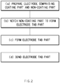
FIG. 2 is a flowchart illustrating a method for manufacturing the electrode according to the first embodiment of the present invention. -
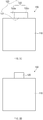
FIGS. 3A to 3D are process views illustrating the method for manufacturing the electrode according to the first embodiment, whereinFIG. 3A is a plan view illustrating an electrode preparation step,FIG. 3B is a plan view illustrating a notching step,FIG. 3C is a plan view illustrating a forming step, andFIG. 3D is a plan view illustrating a bonding step. -
FIG. 4 is an exploded perspective view of an electrode assembly according to a second embodiment of the present invention. -
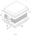
FIG. 5 is an exploded perspective view of a secondary battery according to a third embodiment of the present invention. -
FIG. 6 is a perspective view of an electrode according to a fourth embodiment of the present invention. -
FIG. 7 is a perspective view of an electrode according to a fifth embodiment of the present invention. -
FIG. 8 is a perspective view of an electrode according to a sixth embodiment of the present invention. - Hereinafter, embodiments of the present invention will be described in detail with reference to the accompanying drawings in such a manner that the technical idea of the present invention may easily be carried out by a person with ordinary skill in the art to which the invention pertains. The present invention may, however, be embodied in different forms and should not be construed as limited to the embodiments set forth herein. In the drawings, anything unnecessary for describing the present invention will be omitted for clarity, and also like reference numerals in the drawings denote like elements.
- As illustrated in
FIG. 1 , anelectrode 100 according to a first embodiment of the present invention comprises acoating part 110 coated with an electrode active material and anelectrode tab part 120 provided at one side of thecoating part 110 without containing the electrode active material. - That is, in the
electrode 100 according to the first embodiment of the present invention, the electrode active material is applied to one side of a collector made of a metal material to form thecoating part 110, and a non-coating part, on which the electrode active material is not applied, is notched on the other side of the collector to form theelectrode tab part 120. - The
electrode tab part 120 may have a structure that is reinforced in rigidity so as to be prevented from being bent or folded by a load. That is, theelectrode tab part 120 comprises a first electrode tab connected to one side of thecoating part 110 and a second electrode tab overlapping one surface of the first electrode tab. As described above, theelectrode tab part 120 may reinforce the rigidity of theelectrode tab part 120 through a double structure comprising the first and second electrode tabs to prevent theelectrode tab part 120 from being bent by the load. - For example, referring to
FIG. 1 , theelectrode tab part 120 comprises afirst electrode tab 121 connected to one side of thecoating part 110 and asecond electrode tab 122 connected to thefirst electrode tab 121 and bent in a direction of thefirst electrode tab 121 to overlap one surface of thefirst electrode tab 121. Here, thesecond electrode tab 122 comprises first andsecond connection pieces first electrode tab 121. The first andsecond connection pieces FIG. 1 ) to overlap the one surface of thefirst electrode tab 121. That is, thefirst connection piece 122a is bent with respect to a boundary between thefirst connection piece 122a and thefirst electrode tab 121 to overlap one side of one surface of thefirst electrode tab 121, and thesecond connection piece 122b is bent with respect to a boundary between thesecond connection piece 122b and thefirst electrode tab 121 to overlap the other side of the one surface of thefirst electrode tab 121. - The
electrode tab part 120 having the above-described structure may significantly increase in rigidity through the double structure of the first andsecond electrode tabs electrode tab part 120 from being bent. - The corresponding surfaces of the first and
second connection pieces first electrode tab 121, may be closely attached to each other. That is, the corresponding surfaces of the first andsecond connection pieces second connection pieces electrode tab part 120 to minimize an increase in thickness. Particularly, an accident due to introduction of foreign substances between the first andsecond connection pieces - The
first electrode tab 121 and thesecond electrode tab 122 may have the same area. That is, thefirst electrode tab 121 and thesecond electrode tab 122 may overlap each other with the same area to reinforce the rigidity of the entire one surface of thefirst electrode tab 121. - The
first electrode tab 121 and thesecond electrode tab 122 may be bonded to each other through welding. That is, thefirst electrode tab 121 and thesecond electrode tab 122 may be integrally bonded to each other through the welding without being separated from each other. Thus, adhesion force and bonding force between thefirst electrode tab 121 and thesecond electrode tab 122 may increase. - Thus, the
electrode 100 according to the first embodiment of the present invention comprises the electrode tab part constituted by thefirst electrode tab 121 and thesecond electrode tab 122. Thus, theelectrode tab part 120 may significantly increase in rigidity to prevent theelectrode tab part 120 from being bent by the load. Particularly, theelectrode tab part 120 may be constituted by thefirst electrode tab 121 and thesecond electrode tab 122 to significantly reduce resistance, thereby improving safety of the electrode. - The
first electrode tab 121 and thesecond electrode tab 122 may have thicknesses different from each other. That is, thesecond electrode tab 122 may have a thickness less than that of thefirst electrode tab 121. Thus, thesecond electrode tab 121 may be easily bent to overlap thefirst electrode tab 121. Also, the boundary between thefirst electrode tab 121 and thesecond electrode tab 122 may be easily identified without a separate notice. - Hereinafter, a method for the
electrode 100 according to the first embodiment of the present invention will be described. - As illustrated in
FIG. 2 , a method for manufacturing an electrode according to the first embodiment of the present invention comprises a step (a) of preparing a unfinished electrode comprising a coating part coated with an electrode active material and a non-coating part to which the electrode active material is not applied, a step (b) of notching the non-coating part to form an electrode tab part, and a step (c) of forming the electrode tab part. - Referring to
FIG. 3A , in the step (a), theunfinished electrode 100a comprising thecoating part 110 coated with the electrode active material on one side thereof and thenon-coating part 120a, to which the electrode active material is not applied, on the other side thereof is prepared. - Referring to
FIG. 3B , in the step (b), thenon-coating part 120a formed on theunfinished electrode 100a is notched to form theelectrode tab part 120. Theelectrode tab part 120 comprises afirst electrode tab 121 connected to one side of thecoating part 110 and asecond electrode tab 122 connected to thefirst electrode tab 121. Here, thesecond electrode tab 122 comprises afirst connection piece 122a connected to one side surface of thefirst electrode tab 121 and asecond connection piece 122b connected to the other side surface of thesecond electrode tab 121. - In more detail, the step (b) comprises a first process of notching the
non-coating part 120a along a dotted line displayed inFIG. 3A and a second process of notching thenon-coating part 120a along a dotted line displayed inFIG. 3B . Here, in the second process, each of both sides of the boundary formed between thenon-coating part 120a and thecoating part 110 is notched at each of quarters of the boundary. As a result, the electrode tab part 120b comprising thefirst electrode tab 121 connected to thecoating part 110 and thesecond electrode tab 122 comprising the first andsecond connection pieces first electrode tab 121. - As illustrated in
FIG. 3C , in the step (c), thesecond electrode tab 122 is bent in a direction of thefirst electrode tab 121 to allow thesecond electrode tab 122 to overlap one surface of thefirst electrode tab 121. Thus, as illustrated inFIG. 3D , theelectrode tab part 120 may be completed. - After the step (c), a step (d) of bonding the overlapping first and
second electrode tabs second electrode tabs second electrode tabs - Hereinafter, in descriptions of another embodiment of the present invention, constituents having the same configuration and function as the abovementioned embodiment have been given the same reference numeral in the drawings, and thus duplicated description will be omitted.
- As illustrated in
FIG. 4 , anelectrode assembly 10 according to a second embodiment of the present invention comprises a plurality ofelectrodes 100 and aseparator 200 interposed between the plurality ofelectrodes 100. The plurality ofelectrodes 100 comprise acoating part 110 coated with an electrode active material and anelectrode tab part 120 connected to one side of thecoating part 110. - Here, in the
electrode assembly 10 according to the second embodiment of the present invention, theelectrode tab part 120 comprises afirst electrode tab 121 connected to one side of thecoating part 110 and asecond electrode tab 122 connected to thefirst electrode tab 121 and bent in a direction of thefirst electrode tab 121 to overlap one surface of thefirst electrode tab 121. - The
electrode tab part 120 has the same configuration and function as the electrode tab part according to the first embodiment, and thus, its detailed description will be omitted. - In the
electrode assembly 10 having the above-described configuration according to the second embodiment of the present invention, theelectrode tab part 120 formed on theelectrode 100 may increase in rigidity to prevent theelectrode tab part 120 from being bent or folded, thereby significantly reducing a defective rate of theelectrode assembly 10. Particularly, when the electrode assembly is manufactured, theelectrode 100 is transferred through a roller. Here, theelectrode tab part 120 formed on theelectrode 100 may be prevented from being caught by the roller to prevent theelectrode tab part 120 from being folded or damaged. - As illustrated in
FIG. 5 , asecondary battery 1 according to a third embodiment of the present invention comprises anelectrode assembly 10 and apouch 20 accommodating theelectrode assembly 10. Theelectrode assembly 10 comprises a plurality ofelectrodes 100 and aseparator 200 interposed between the plurality ofelectrodes 100. The plurality ofelectrodes 100 comprise acoating part 110 coated with an electrode active material and anelectrode tab part 120 connected to one side of thecoating part 110. - The
electrode tab part 120 comprises afirst electrode tab 121 connected to one side of thecoating part 110 and asecond electrode tab 122 connected to thefirst electrode tab 121 and bent in a direction of thefirst electrode tab 121 to overlap one surface of thefirst electrode tab 121. - Here, in the
secondary battery 1 according to the third embodiment of the present invention, theelectrode tab part 1 comprises afirst electrode tab 121 connected to one side of thecoating part 110 and asecond electrode tab 122 connected to thefirst electrode tab 121 and bent in a direction of thefirst electrode tab 121 to overlap one surface of thefirst electrode tab 121. - The
electrode tab part 120 has the same configuration and function as the electrode tab part according to the first embodiment, and thus, its detailed description will be omitted. - In the
secondary battery 1 having the above-described configuration according to the second embodiment of the present invention, theelectrode tab part 120 formed on theelectrode 100 may increase in rigidity to prevent theelectrode tab part 120 from being bent or folded, thereby significantly reducing a defective rate of thesecondary battery 10. - As illustrated in
FIG. 6 , anelectrode 100A according to a fourth embodiment of the present invention comprises acoating part 110 coated with an electrode active material and anelectrode tab part 120 provided on one side of thecoating part 110. Theelectrode tab part 120 comprises afirst electrode tab 121 connected to one side of thecoating part 110 and asecond electrode tab 122 connected to thefirst electrode tab 121 and bent in a direction of thefirst electrode tab 121 to overlap one surface of thefirst electrode tab 121. - Here, the
second electrode tab 122 is connected to one side surface of the first electrode tab 121 (a right surface of the first electrode tab when viewed inFIG. 6 ) and bent in a direction of the first electrode tab 121 (a direction of a top surface of the first electrode tab when viewed inFIG. 6 ) to overlap one surface of thefirst electrode tab 121. - Thus, in the
electrode 100A according to the fourth embodiment of the present invention, the firstelectrode tab part 120 may be more easily notched and bent to improve work efficiency. - As illustrated in
FIG. 7 , anelectrode 100B according to a fifth embodiment of the present invention comprises acoating part 110 coated with an electrode active material and anelectrode tab part 120 provided on one side of thecoating part 110. Theelectrode tab part 120 comprises afirst electrode tab 121 connected to one side of thecoating part 110 and asecond electrode tab 122 connected to thefirst electrode tab 121 and bent in a direction of thefirst electrode tab 121 to overlap one surface of thefirst electrode tab 121. - Here, the
second electrode tab 122 may be connected to a front end surface of thefirst electrode tab 121 and bent in the direction of thefirst electrode tab 121 to overlap the one surface of thefirst electrode tab 121. - Thus, in the
electrode 100B according to the fifth embodiment of the present invention, the firstelectrode tab part 120 may be more easily notched and bent to improve work efficiency. - As illustrated in
FIG. 8 , an electrode 100C according to a sixth embodiment of the present invention comprises acoating part 110 coated with an electrode active material and anelectrode tab part 120 provided on one side of thecoating part 110. Theelectrode tab part 120 comprises afirst electrode tab 121 connected to one side of thecoating part 110 and asecond electrode tab 122 connected to thefirst electrode tab 121 and bent in a direction of thefirst electrode tab 121 to overlap one surface of thefirst electrode tab 121. - The second electrode tab comprises first and second connection pieces respectively connected to both side surfaces of the first electrode tab. The first connection piece is bent in a direction of one surface of the first electrode tab to overlap the one surface of the first electrode tab, and the second connection piece is bent in a direction of the other surface of the first electrode tab to overlap the other surface of the first electrode tab.
- Thus, in the electrode 100C according to the sixth embodiment of the present invention, the
electrode tab part 120 may significantly increase in rigidity. - Accordingly, the scope of the present invention is defined by the appended claims rather than the foregoing description and the exemplary embodiments described therein. Various modifications made within the meaning of an equivalent of the claims of the invention and within the claims are to be regarded to be in the scope of the present invention.
Claims (13)
- An electrode comprising:a coating part coated with an electrode active material; andan electrode tab part provided on one side of the coating part,wherein the electrode tab part comprises:a first electrode tab connected to the one side of the coating part; anda second electrode tab connected to the first electrode tab and bent in a direction of the first electrode tab to overlap one surface of the first electrode tab.
- The electrode of claim 1, wherein the second electrode tab comprises first and second connection pieces respectively connected to both side surfaces of the first electrode tab, and
the first and second connection pieces are bent in a direction of the one surface of the first electrode tab to correspondingly overlap the one surface of the first electrode tab. - The electrode of claim 2, wherein corresponding surfaces of the first and second connection pieces overlapping the first electrode tab are closely attached to each other.
- The electrode of claim 1, wherein the second electrode tab is connected to one side surface of the first electrode tab and bent in a direction of the first electrode tab to overlap the one surface of the first electrode tab.
- The electrode of claim 1, wherein the second electrode tab is connected to a front end surface of the first electrode tab and bent in a direction of the first electrode tab to overlap the one surface of the first electrode tab.
- The electrode of claim 1, wherein the second electrode tab comprises first and second connection pieces respectively connected to both side surfaces of the first electrode tab,
wherein the first connection piece is bent in a direction of one surface of the first electrode tab to overlap the one surface of the first electrode tab, and
the second connection piece is bent in a direction of the other surface of the first electrode tab to overlap the other surface of the first electrode tab. - The electrode of any one of claims 2 to 5, wherein the first electrode tab and the second electrode tab have the same area.
- The electrode of claim 1, wherein the first electrode tab and the second electrode tab are integrally bonded to each other through welding.
- A method for manufacturing an electrode, the method comprising:a step (a) of preparing a unfinished electrode comprising a coating part coated with an electrode active material and a non-coating part to which the electrode active material is not applied;a step (b) of notching the non-coating part to form an electrode tab part, wherein the electrode tab part comprises a first electrode tab connected to one side of the coating part and a second electrode tab connected to the first electrode tab; anda step (c) of bending the second electrode tab in a direction of the first electrode tab to allow the second electrode tab to overlap one surface of the first electrode tab.
- The method of claim 9, wherein the step (b) comprises:a first process of primarily notching both ends of the non-coating part formed on the unfinished electrode to form a primarily processed electrode tab part; anda second process of secondarily notching both sides of a boundary formed between the primarily processed electrode tab part and the coating part at each of quarters of the boundary to form an electrode tab part comprising a first electrode tab connected to the coating part and a second electrode tab comprising first and second connection pieces respectively connected to both side surfaces of the first electrode tab.
- The method of claim 10, further comprising, after the step (c), a step (d) of bonding the overlapping first and second electrode tabs to each other.
- An electrode assembly comprising:a plurality of electrodes; anda separator interposed between the plurality of electrodes,wherein each of the plurality of electrodes comprises:a coating part coated with an electrode active material; andan electrode tab part connected to one side of the coating part,wherein the electrode tab part comprises:a first electrode tab connected to the one side of the coating part; anda second electrode tab connected to the first electrode tab and bent in a direction of the first electrode tab to overlap one surface of the first electrode tab.
- A secondary battery comprising:an electrode assembly; anda pouch accommodating the electrode assembly,wherein the electrode assembly comprises:a plurality of electrodes; anda separator interposed between the plurality of electrodes,wherein each of the plurality of electrodes comprises:a coating part coated with an electrode active material; andan electrode tab part connected to one side of the coating part,wherein the electrode tab part comprises:a first electrode tab connected to the one side of the coating part; anda second electrode tab connected to the first electrode tab and bent in a direction of the first electrode tab to overlap one surface of the first electrode tab.
Applications Claiming Priority (2)
| Application Number | Priority Date | Filing Date | Title |
|---|---|---|---|
| KR1020170167727A KR102270867B1 (en) | 2017-12-07 | 2017-12-07 | Electrode, method for manufacturing the same, electrode assembly and secondary battery |
| PCT/KR2018/013738 WO2019112196A1 (en) | 2017-12-07 | 2018-11-12 | Electrode, method for manufacturing same, electrode assembly, and secondary battery |
Publications (3)
| Publication Number | Publication Date |
|---|---|
| EP3605661A1 true EP3605661A1 (en) | 2020-02-05 |
| EP3605661A4 EP3605661A4 (en) | 2020-06-03 |
| EP3605661B1 EP3605661B1 (en) | 2025-12-31 |
Family
ID=66750271
Family Applications (1)
| Application Number | Title | Priority Date | Filing Date |
|---|---|---|---|
| EP18885232.1A Active EP3605661B1 (en) | 2017-12-07 | 2018-11-12 | ELECTRODE, MANUFACTURING METHOD FOR IT, ELECTRODE ASSEMBLY AND SECONDARY BATTERY |
Country Status (6)
| Country | Link |
|---|---|
| US (1) | US11456445B2 (en) |
| EP (1) | EP3605661B1 (en) |
| KR (1) | KR102270867B1 (en) |
| CN (1) | CN110495018B (en) |
| ES (1) | ES3059869T3 (en) |
| WO (1) | WO2019112196A1 (en) |
Families Citing this family (3)
| Publication number | Priority date | Publication date | Assignee | Title |
|---|---|---|---|---|
| WO2022021227A1 (en) * | 2020-07-30 | 2022-02-03 | 东莞新能安科技有限公司 | Electrode plate, electrochemical device and electronic device |
| WO2022082446A1 (en) * | 2020-10-20 | 2022-04-28 | 宁德时代新能源科技股份有限公司 | Electrode assembly, battery cell, battery, electric apparatus, and manufacturing method and device |
| CN114614069B (en) * | 2022-05-09 | 2022-08-26 | 宁德时代新能源科技股份有限公司 | Battery cell and manufacturing method, battery and electrical device |
Family Cites Families (32)
| Publication number | Priority date | Publication date | Assignee | Title |
|---|---|---|---|---|
| KR0178303B1 (en) | 1995-10-27 | 1999-04-15 | 김은영 | Epi growth rate control method on the side of semiconductor pattern using CBr4 gas |
| JP2001250516A (en) * | 2000-03-06 | 2001-09-14 | Mitsubishi Chemicals Corp | Battery |
| JP4797236B2 (en) | 2000-11-17 | 2011-10-19 | 株式会社Gsユアサ | battery |
| JP2005317367A (en) * | 2004-04-28 | 2005-11-10 | Sanyo Electric Co Ltd | Pack battery |
| US20060008702A1 (en) | 2004-06-23 | 2006-01-12 | Sang-Eun Cheon | Secondary battery |
| KR100648702B1 (en) * | 2005-03-08 | 2006-11-23 | 삼성에스디아이 주식회사 | Secondary Battery and Electrode Assembly Used in the Same |
| JP2006019075A (en) | 2004-06-30 | 2006-01-19 | Nissan Motor Co Ltd | Flat battery and assembled battery using the battery |
| JP2006032112A (en) * | 2004-07-15 | 2006-02-02 | Matsushita Electric Ind Co Ltd | Electrochemical element |
| KR100670514B1 (en) | 2005-05-18 | 2007-01-16 | 삼성에스디아이 주식회사 | Pouch Type Secondary Battery |
| WO2007052652A1 (en) * | 2005-11-01 | 2007-05-10 | Showa Denko K. K. | Solid electrolytic capacitor and method for manufacturing same |
| JP5550805B2 (en) | 2006-07-18 | 2014-07-16 | エルジー・ケム・リミテッド | Electrode assembly having stable electrode lead-electrode tab joint and electrochemical cell having the same |
| JP2008091036A (en) * | 2006-09-29 | 2008-04-17 | Nec Tokin Corp | Battery pack |
| JP2008117614A (en) * | 2006-11-02 | 2008-05-22 | Sony Corp | Current collector for electrode and non-aqueous electrolyte secondary battery |
| KR100947071B1 (en) | 2007-11-23 | 2010-03-12 | 삼성에스디아이 주식회사 | Secondary battery |
| CN102035013B (en) * | 2009-10-01 | 2014-08-13 | 三星Sdi株式会社 | Secondary battery and method of fabricating secondary battery |
| KR100989839B1 (en) | 2009-11-30 | 2010-10-29 | 삼성에스디아이 주식회사 | Secondary battery |
| KR20140145787A (en) * | 2013-06-14 | 2014-12-24 | 삼성에스디아이 주식회사 | Rechargeable battery pack |
| JP2015126164A (en) | 2013-12-27 | 2015-07-06 | ダイハツ工業株式会社 | Electrochemical cell |
| JP6274034B2 (en) * | 2014-06-30 | 2018-02-07 | 株式会社豊田自動織機 | Power storage device |
| WO2016006420A1 (en) | 2014-07-10 | 2016-01-14 | 株式会社村田製作所 | Method of manufacturing power storage device and method of manufacturing electrode |
| KR102257679B1 (en) * | 2014-09-17 | 2021-05-28 | 삼성에스디아이 주식회사 | Secondary Battery |
| KR101775230B1 (en) | 2014-10-02 | 2017-09-05 | 주식회사 엘지화학 | Laminating apparatus and method for secondary battery |
| KR102394689B1 (en) * | 2014-11-24 | 2022-05-06 | 삼성에스디아이 주식회사 | Flexible secondary battery |
| KR101722820B1 (en) * | 2014-12-11 | 2017-04-03 | 에스케이이노베이션 주식회사 | Secondary battery having electrode tab |
| KR20160107643A (en) | 2015-03-04 | 2016-09-19 | 주식회사 코캄 | Connecting structure and method between grid and electrode-tab of secondary battery |
| KR101809208B1 (en) * | 2015-06-16 | 2017-12-14 | 주식회사 엘지화학 | Secondary battery and method for fabricating the same |
| KR102439847B1 (en) * | 2015-08-25 | 2022-09-01 | 삼성에스디아이 주식회사 | secondary battery |
| KR102028737B1 (en) | 2015-10-15 | 2019-10-04 | 주식회사 엘지화학 | Pouch-typed Battery Cell Having Electrode Lead of Folded Structure |
| KR20170083703A (en) * | 2016-01-08 | 2017-07-19 | 현대로보틱스주식회사 | Transfer Robot having Removing Foreign Substance Function |
| CN105720226B (en) * | 2016-02-24 | 2018-06-19 | 深圳市海盈科技股份有限公司 | Soft bag lithium ionic cell and its anode ear welding method |
| KR101783703B1 (en) * | 2017-03-17 | 2017-10-11 | 주식회사 리베스트 | Flexible battery having joint structure metal strengthening tab and bending joint structure |
| KR20170101857A (en) * | 2017-08-23 | 2017-09-06 | 주식회사 코캄 | Connecting structure and method between grid and electrode-tab of secondary battery |
-
2017
- 2017-12-07 KR KR1020170167727A patent/KR102270867B1/en active Active
-
2018
- 2018-11-12 WO PCT/KR2018/013738 patent/WO2019112196A1/en not_active Ceased
- 2018-11-12 EP EP18885232.1A patent/EP3605661B1/en active Active
- 2018-11-12 CN CN201880024014.3A patent/CN110495018B/en active Active
- 2018-11-12 US US16/607,230 patent/US11456445B2/en active Active
- 2018-11-12 ES ES18885232T patent/ES3059869T3/en active Active
Also Published As
| Publication number | Publication date |
|---|---|
| EP3605661B1 (en) | 2025-12-31 |
| ES3059869T3 (en) | 2026-03-24 |
| KR102270867B1 (en) | 2021-07-01 |
| CN110495018B (en) | 2022-04-26 |
| KR20190067612A (en) | 2019-06-17 |
| US11456445B2 (en) | 2022-09-27 |
| US20200388819A1 (en) | 2020-12-10 |
| CN110495018A (en) | 2019-11-22 |
| WO2019112196A1 (en) | 2019-06-13 |
| EP3605661A4 (en) | 2020-06-03 |
Similar Documents
| Publication | Publication Date | Title |
|---|---|---|
| US11757124B2 (en) | Electrode assembly for secondary battery and method for manufacturing the same | |
| US20250070191A1 (en) | Current collecting member and secondary battery | |
| US8956753B2 (en) | Secondary battery and secondary battery module | |
| EP2858162B1 (en) | Electrode assembly including steps having corner portions of various shapes, battery cell, battery pack, and device including same | |
| EP2919311B1 (en) | Flexible jelly roll type secondary battery | |
| US11728466B2 (en) | Secondary battery | |
| EP3624208B1 (en) | Cell packaging structure | |
| EP3605661B1 (en) | ELECTRODE, MANUFACTURING METHOD FOR IT, ELECTRODE ASSEMBLY AND SECONDARY BATTERY | |
| US20160218386A1 (en) | Rechargeable battery | |
| US11043669B2 (en) | Electrode and secondary battery comprising the same | |
| KR20150007741A (en) | rechargeable battery | |
| US10505232B2 (en) | Stacked, rolled-electrode battery cell with y-axis bending | |
| EP3249733B1 (en) | Secondary battery | |
| KR102058098B1 (en) | Flexible electrode assembly having strengthening structure using expanded metal on outermost electrode | |
| US11967734B2 (en) | Electrode assembly, secondary battery comprising the same, method for manufacturing secondary battery, and battery pack | |
| KR102749730B1 (en) | Electrode Assembly and Secondary Battery Comprising the Same | |
| KR20200075558A (en) | Electrode, electrode assembly comprising the same, manufacturing method for electrode assembly and secondary battery | |
| KR102237948B1 (en) | Electrode, electrode assembly and method for preparing the same | |
| US20180053927A1 (en) | Stacked-Electrode Battery Cell | |
| KR102058099B1 (en) | Flexible electrode assembly having strengthening structure using expanded metal on outermost electrode and inner electrode | |
| EP4287387B1 (en) | Electrode assembly including electrode tabs of metalized film and metal connector connecting them, and secondary battery comprising the same | |
| KR102928368B1 (en) | Electrode assembly and method for manufacturing the same, secondary battery | |
| KR20220052610A (en) | Electrode for secondary battery, and secondary battery including the same | |
| KR20170109394A (en) | Electrode assembly and secondary battery comprising the same |
Legal Events
| Date | Code | Title | Description |
|---|---|---|---|
| STAA | Information on the status of an ep patent application or granted ep patent |
Free format text: STATUS: THE INTERNATIONAL PUBLICATION HAS BEEN MADE |
|
| PUAI | Public reference made under article 153(3) epc to a published international application that has entered the european phase |
Free format text: ORIGINAL CODE: 0009012 |
|
| STAA | Information on the status of an ep patent application or granted ep patent |
Free format text: STATUS: REQUEST FOR EXAMINATION WAS MADE |
|
| 17P | Request for examination filed |
Effective date: 20191021 |
|
| AK | Designated contracting states |
Kind code of ref document: A1 Designated state(s): AL AT BE BG CH CY CZ DE DK EE ES FI FR GB GR HR HU IE IS IT LI LT LU LV MC MK MT NL NO PL PT RO RS SE SI SK SM TR |
|
| AX | Request for extension of the european patent |
Extension state: BA ME |
|
| A4 | Supplementary search report drawn up and despatched |
Effective date: 20200506 |
|
| RIC1 | Information provided on ipc code assigned before grant |
Ipc: H01M 2/26 20060101AFI20200428BHEP Ipc: H01M 10/04 20060101ALI20200428BHEP Ipc: H01M 4/04 20060101ALI20200428BHEP |
|
| DAV | Request for validation of the european patent (deleted) | ||
| DAX | Request for extension of the european patent (deleted) | ||
| RAP1 | Party data changed (applicant data changed or rights of an application transferred) |
Owner name: LG ENERGY SOLUTION LTD. |
|
| RAP3 | Party data changed (applicant data changed or rights of an application transferred) |
Owner name: LG ENERGY SOLUTION, LTD. |
|
| STAA | Information on the status of an ep patent application or granted ep patent |
Free format text: STATUS: EXAMINATION IS IN PROGRESS |
|
| 17Q | First examination report despatched |
Effective date: 20241007 |
|
| REG | Reference to a national code |
Ref country code: DE Ref legal event code: R079 Free format text: PREVIOUS MAIN CLASS: H01M0002260000 Ipc: H01M0010040000 Ref country code: DE Ref legal event code: R079 Ref document number: 602018088354 Country of ref document: DE Free format text: PREVIOUS MAIN CLASS: H01M0002260000 Ipc: H01M0010040000 |
|
| RIC1 | Information provided on ipc code assigned before grant |
Ipc: H01M 4/04 20060101ALI20250605BHEP Ipc: H01M 10/04 20060101AFI20250605BHEP |
|
| GRAP | Despatch of communication of intention to grant a patent |
Free format text: ORIGINAL CODE: EPIDOSNIGR1 |
|
| STAA | Information on the status of an ep patent application or granted ep patent |
Free format text: STATUS: GRANT OF PATENT IS INTENDED |
|
| INTG | Intention to grant announced |
Effective date: 20250711 |
|
| P01 | Opt-out of the competence of the unified patent court (upc) registered |
Free format text: CASE NUMBER: UPC_APP_4862_3605661/2025 Effective date: 20250827 |
|
| GRAS | Grant fee paid |
Free format text: ORIGINAL CODE: EPIDOSNIGR3 |
|
| GRAA | (expected) grant |
Free format text: ORIGINAL CODE: 0009210 |
|
| STAA | Information on the status of an ep patent application or granted ep patent |
Free format text: STATUS: THE PATENT HAS BEEN GRANTED |
|
| AK | Designated contracting states |
Kind code of ref document: B1 Designated state(s): AL AT BE BG CH CY CZ DE DK EE ES FI FR GB GR HR HU IE IS IT LI LT LU LV MC MK MT NL NO PL PT RO RS SE SI SK SM TR |
|
| REG | Reference to a national code |
Ref country code: CH Ref legal event code: F10 Free format text: ST27 STATUS EVENT CODE: U-0-0-F10-F00 (AS PROVIDED BY THE NATIONAL OFFICE) Effective date: 20251231 Ref country code: GB Ref legal event code: FG4D |
|
| REG | Reference to a national code |
Ref country code: DE Ref legal event code: R096 Ref document number: 602018088354 Country of ref document: DE |
|
| REG | Reference to a national code |
Ref country code: IE Ref legal event code: FG4D |
|
| REG | Reference to a national code |
Ref country code: ES Ref legal event code: FG2A Ref document number: 3059869 Country of ref document: ES Kind code of ref document: T3 Effective date: 20260324 |
|
| REG | Reference to a national code |
Ref country code: LT Ref legal event code: MG9D |
|
| PG25 | Lapsed in a contracting state [announced via postgrant information from national office to epo] |
Ref country code: NO Free format text: LAPSE BECAUSE OF FAILURE TO SUBMIT A TRANSLATION OF THE DESCRIPTION OR TO PAY THE FEE WITHIN THE PRESCRIBED TIME-LIMIT Effective date: 20260331 |
|
| PG25 | Lapsed in a contracting state [announced via postgrant information from national office to epo] |
Ref country code: FI Free format text: LAPSE BECAUSE OF FAILURE TO SUBMIT A TRANSLATION OF THE DESCRIPTION OR TO PAY THE FEE WITHIN THE PRESCRIBED TIME-LIMIT Effective date: 20251231 Ref country code: HR Free format text: LAPSE BECAUSE OF FAILURE TO SUBMIT A TRANSLATION OF THE DESCRIPTION OR TO PAY THE FEE WITHIN THE PRESCRIBED TIME-LIMIT Effective date: 20251231 |
|
| PG25 | Lapsed in a contracting state [announced via postgrant information from national office to epo] |
Ref country code: RS Free format text: LAPSE BECAUSE OF FAILURE TO SUBMIT A TRANSLATION OF THE DESCRIPTION OR TO PAY THE FEE WITHIN THE PRESCRIBED TIME-LIMIT Effective date: 20260331 |
|
| PG25 | Lapsed in a contracting state [announced via postgrant information from national office to epo] |
Ref country code: LV Free format text: LAPSE BECAUSE OF FAILURE TO SUBMIT A TRANSLATION OF THE DESCRIPTION OR TO PAY THE FEE WITHIN THE PRESCRIBED TIME-LIMIT Effective date: 20251231 |
|
| PG25 | Lapsed in a contracting state [announced via postgrant information from national office to epo] |
Ref country code: BG Free format text: LAPSE BECAUSE OF FAILURE TO SUBMIT A TRANSLATION OF THE DESCRIPTION OR TO PAY THE FEE WITHIN THE PRESCRIBED TIME-LIMIT Effective date: 20251231 |
|
| REG | Reference to a national code |
Ref country code: NL Ref legal event code: MP Effective date: 20251231 |