EP3605658A1 - Flexible copper busbar and method and apparatus for designing flexible copper busbar of power battery - Google Patents
Flexible copper busbar and method and apparatus for designing flexible copper busbar of power battery Download PDFInfo
- Publication number
- EP3605658A1 EP3605658A1 EP19174680.9A EP19174680A EP3605658A1 EP 3605658 A1 EP3605658 A1 EP 3605658A1 EP 19174680 A EP19174680 A EP 19174680A EP 3605658 A1 EP3605658 A1 EP 3605658A1
- Authority
- EP
- European Patent Office
- Prior art keywords
- flexible copper
- copper busbar
- battery module
- battery
- finite element
- Prior art date
- Legal status (The legal status is an assumption and is not a legal conclusion. Google has not performed a legal analysis and makes no representation as to the accuracy of the status listed.)
- Granted
Links
Images


Classifications
-
- G—PHYSICS
- G06—COMPUTING OR CALCULATING; COUNTING
- G06F—ELECTRIC DIGITAL DATA PROCESSING
- G06F30/00—Computer-aided design [CAD]
- G06F30/20—Design optimisation, verification or simulation
- G06F30/23—Design optimisation, verification or simulation using finite element methods [FEM] or finite difference methods [FDM]
-
- H—ELECTRICITY
- H01—ELECTRIC ELEMENTS
- H01M—PROCESSES OR MEANS, e.g. BATTERIES, FOR THE DIRECT CONVERSION OF CHEMICAL ENERGY INTO ELECTRICAL ENERGY
- H01M50/00—Constructional details or processes of manufacture of the non-active parts of electrochemical cells other than fuel cells, e.g. hybrid cells
- H01M50/50—Current conducting connections for cells or batteries
- H01M50/502—Interconnectors for connecting terminals of adjacent batteries; Interconnectors for connecting cells outside a battery casing
- H01M50/521—Interconnectors for connecting terminals of adjacent batteries; Interconnectors for connecting cells outside a battery casing characterised by the material
- H01M50/522—Inorganic material
-
- H—ELECTRICITY
- H01—ELECTRIC ELEMENTS
- H01M—PROCESSES OR MEANS, e.g. BATTERIES, FOR THE DIRECT CONVERSION OF CHEMICAL ENERGY INTO ELECTRICAL ENERGY
- H01M50/00—Constructional details or processes of manufacture of the non-active parts of electrochemical cells other than fuel cells, e.g. hybrid cells
- H01M50/50—Current conducting connections for cells or batteries
- H01M50/502—Interconnectors for connecting terminals of adjacent batteries; Interconnectors for connecting cells outside a battery casing
- H01M50/503—Interconnectors for connecting terminals of adjacent batteries; Interconnectors for connecting cells outside a battery casing characterised by the shape of the interconnectors
-
- H—ELECTRICITY
- H01—ELECTRIC ELEMENTS
- H01M—PROCESSES OR MEANS, e.g. BATTERIES, FOR THE DIRECT CONVERSION OF CHEMICAL ENERGY INTO ELECTRICAL ENERGY
- H01M50/00—Constructional details or processes of manufacture of the non-active parts of electrochemical cells other than fuel cells, e.g. hybrid cells
- H01M50/50—Current conducting connections for cells or batteries
- H01M50/502—Interconnectors for connecting terminals of adjacent batteries; Interconnectors for connecting cells outside a battery casing
- H01M50/505—Interconnectors for connecting terminals of adjacent batteries; Interconnectors for connecting cells outside a battery casing comprising a single busbar
-
- H—ELECTRICITY
- H01—ELECTRIC ELEMENTS
- H01M—PROCESSES OR MEANS, e.g. BATTERIES, FOR THE DIRECT CONVERSION OF CHEMICAL ENERGY INTO ELECTRICAL ENERGY
- H01M2220/00—Batteries for particular applications
-
- Y—GENERAL TAGGING OF NEW TECHNOLOGICAL DEVELOPMENTS; GENERAL TAGGING OF CROSS-SECTIONAL TECHNOLOGIES SPANNING OVER SEVERAL SECTIONS OF THE IPC; TECHNICAL SUBJECTS COVERED BY FORMER USPC CROSS-REFERENCE ART COLLECTIONS [XRACs] AND DIGESTS
- Y02—TECHNOLOGIES OR APPLICATIONS FOR MITIGATION OR ADAPTATION AGAINST CLIMATE CHANGE
- Y02E—REDUCTION OF GREENHOUSE GAS [GHG] EMISSIONS, RELATED TO ENERGY GENERATION, TRANSMISSION OR DISTRIBUTION
- Y02E60/00—Enabling technologies; Technologies with a potential or indirect contribution to GHG emissions mitigation
- Y02E60/10—Energy storage using batteries
Definitions
- the invention relates to the field of power battery, and in particular relates to a flexible copper busbar and a method and apparatus for designing a flexible copper busbar of a power battery.
- a power battery is formed by connecting a plurality of battery modules in series.
- Property of the power battery is directly affected by the design of electric connection structures between battery modules.
- strict requirements are imposed on reliability, electric current carrying capacity and contact resistance between battery modules.
- flexible copper busbars have become one of the most popular electric connection structures between battery modules.
- CAE analysis generally comprises to analyze whether the stress in the flexible copper busbar exceeds a predetermined value in working conditions, such as when the power battery is subjected to vibration or shock.
- CAE modeling faces a big difficulty since the flexible copper busbar is formed by laminating multi layers of thin sheet copper.
- existing flexible copper busbar has a flat plate structure so the flexible copper busbar is easy to be stretched in harsh working conditions, which may further result in decreasing in fatigue life of the flexible copper busbar and changing in contact resistance.
- the invention provides a flexible copper busbar and a method and apparatus for designing a flexible copper busbar of a power battery, with an object of increasing the power battery designing efficiency and ensuring that there is no force transmission in the flexible copper busbar in harsh working conditions so that fatigue life of the flexible copper busbar and stability of contact resistance can be increased.
- a flexible copper busbar comprises: a first connection portion (11), a second connection portion (12), and a convex portion (13) connected between the first connection portion (11) and the second connection portion (12); wherein the first connection portion (11) comprises a first connection hole, and the first connection portion is connected with the first battery module via the first connection hole; and wherein the second connection portion (12) comprises a second connection hole, and the second connection portion is connected with the second battery module via the second connection hole, the first battery module and the second battery module being adjacent to each other.
- the convex portion (13) is configured as arch-shaped or wave-shaped.
- a method for designing the flexible copper busbar described above comprises:
- the safety factor is 2.
- An apparatus for designing the flexible copper busbar described above comprises:
- the above technical solutions provide a flexible copper busbar which comprises a first connection portion (11), a second connection portion (12), and a convex portion (13) connected between the first connection portion (11) and the second connection portion (12).
- the convex portion (13) is stretched to become straightened under a force to become straightened, stress is distributed uniformly without stress concentration, and there is no force transmission. Fatigue life and contact resistance stability of the flexible copper busbar can be increased.
- the above technical solutions provide a method and apparatus for designing the above flexible copper busbar, in which, by analyzing the maximum space between first and second battery modules which are connected with opposite ends of the flexible copper busbar and then determining the total length of the flexible copper busbar, a procedure of investigating the stress by modeling the flexible copper busbar is avoided, and power battery designing efficiency can be increased.
- An embodiment provides a flexible copper busbar, as illustrated in Figure 1 .
- the structure of the flexible copper busbar comprises: a first connection portion 11, a second connection portion 12, and a convex portion 13 connected between the first connection portion 11 and the second connection portion 12.
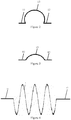
- the convex portion 13 shown in the present embodiment particularly has a shape of a semi-circle.
- the convex portion 13 may alternatively have a shape of other types of arc, such as that shown in Figure 2 and Figure 3 , or have a shape of waves, such as that shown in Figure 4 and Figure 5 .
- the first connection portion 11 comprises a first connection hole and is connected to a first battery module 21 via the first connection hole.
- the second connection portion 12 comprises a second connection hole and is connected to the second battery module 22 via the second connection hole, the first battery module 21 and the second battery module 22 being adjacent to each other.
- connection portion between the first connection portion 11 and the second connection portion 12 By configuring the connection portion between the first connection portion 11 and the second connection portion 12 as the convex portion 13, the convex portion 13 is stretched to become straightened under a force in harsh working conditions, stress is distributed uniformly without stress concentration, and there is no force transmission. Fatigue life and contact resistance stability of the flexible copper busbar can be increased.
- An embodiment further provides a method for designing the above described flexible copper busbar. As illustrated in Figure 6 , the method comprises the steps described below.
- S11 performing mode analysis to a previously established finite element grid model of a power battery to find a direction with a minimum rigidity in the finite element grid model of the power battery.
- a finite element grid model of the power battery is previously defined in "Hypermesh" based on a three-dimensional model of the power battery.
- the finite element grid model of the power battery is a finite element model which reflects real structures of a battery pack casing, a battery module, a high voltage box and a BMS, both the mass of the flexible copper busbar and the mass of the harshness being added into the battery module. That is to say, in the finite element grid model of the power battery, the structures of the harshness and the flexible copper busbar are omitted so that modeling analysis to the flexible copper busbar is avoided, and the masses of the harshness and the flexible copper busbar are given to the battery module so that the result of the analysis is more approximate to the real condition.
- the mass of the battery module equals to the real total mass of the battery module, the harshness and the flexible copper busbar; the structure of the battery module has undergone simplification treatment, and the simplified battery module model comprises a simplified integer of end plates, side plates and all battery cells.
- "tie” treatment is used in the finite element grid model of the power battery; for bolted or welded connections in the battery pack, "rigid unit connection” is used in the finite element grid model of the power battery; for the welded connections in the battery pack, “seam” treatment may alternatively be used in the finite element grid model of the power battery.
- Mode analysis to the finite element grid model of the power battery is performed by using a finite element structure analysis software, such as "optistruct", with full restrains being applied to the mounting point of the power battery, the mode analysis frequency being in the range of 0 ⁇ 200 Hz, and participation factors and effective masses in the directions of 6 DOFs (degrees of freedom) being output.
- a finite element structure analysis software such as "optistruct”
- the mode analysis frequency being in the range of 0 ⁇ 200 Hz
- participation factors and effective masses in the directions of 6 DOFs (degrees of freedom) being output.
- the power battery is mounted to a vehicle
- the driving direction is X-direction
- the height direction is Z-direction
- the transverse direction of the vehicle is Y-direction.
- Basic frequencies in all the directions are determined based on results of the mode analysis.
- the effective mass in Z-direction reaches its maximum level at 20 Hz, so the basic frequency in Z-direction is 20 Hz; it is found by means of analysis that the effective mass in Y-direction reaches its maximum level at 30 Hz, so the basic frequency in Y-direction is 30 Hz; it is found by means of analysis that the effective mass in X-direction reaches its maximum level at 40 Hz, so the basic frequency in X-direction is 40 Hz. Since Z-direction has a lowest basic frequency, the power battery is considered to have a weakest rigidity in Z-direction, that is, the direction with a minimum rigidity in the finite element grid model of the power battery is Z-direction.
- the signal of the extreme mechanical shock working condition corresponds to data presented when a maximum space is created between the first battery module 21 and the second battery module 22.
- the signal of the extreme mechanical shock working condition is an acceleration of (25 g, 15 ms).
- 25 g means 25 times of the acceleration of gravity
- 15 ms represents a half-chord wave having a pulse width of 15 ms.
- a finite element analysis software such as "ls-dyna"
- DOFs in all 5 directions except Z-direction are restrained
- the signal of (25g, 15ms) is applied in Z-direction to the mounting point of the power battery, and corresponding relation of the space between the first battery module 21 and the second battery module 22 vs. time is obtained; and then the maximum space L1 between first battery module 21 and second battery module 22 can be obtained.
- Existing mode analysis methods and mechanical shock analysis methods can all be used in the present embodiment, and the invention imposes no limitation to concrete mode analysis procedures and mechanical shock analysis procedures.
- the total length L4 is the distance between the opposite ends of the flexible copper busbar in the condition that the flexible copper busbar is under a pulling force and the convex portion 13 is stretched to become straightened.
- L3 is the distance between the opposite ends of the flexible copper busbar in the condition that the flexible copper busbar is free of any pulling force.
- the value of the safety factor is selected from a range of [1, 3]. In a particular embodiment, the safety factor is selected to be 2, as a result of which, fatigue life and contact resistance stability of the flexible copper busbar can be increased on one hand, and there is little material waste on the other hand.
- An embodiment further provides an apparatus for designing the above described flexible copper busbar.
- the apparatus comprises: a mode analysis unit U11, a data acquiring unit U12, a mechanical shock analysis unit U13 and a total length calculating unit U14.
- the mode analysis unit U11 is configured to perform mode analysis to a previously established finite element grid model of a power battery to find a direction with a minimum rigidity in the finite element grid model of the power battery, the finite element grid model of the power battery being a finite element model in which real structures of a battery pack casing, battery modules, a high voltage box and a BMS are reflected, and the mass of the flexible copper busbar and the mass of the harshness being added to the battery module.
- the data acquiring unit U12 is configured to obtain a signal of an extreme mechanical shock working condition, the signal of the extreme mechanical shock working condition corresponding to data presented when a maximum space is created between the first battery module and the second battery module.
- the mechanical shock analysis unit U13 is configured to apply the signal of the extreme mechanical shock working condition in the direction with the minimum rigidity in the finite element grid model of the power battery to perform mechanical shock analysis in which the maximum space between the first battery module and the second battery module is obtained.
- the total length calculating unit U14 is configured to subtract an initial space between the first battery module and the second battery module from the maximum space, to multiply the result thus obtained by a predetermined safety factor, and then to add an initial space between opposite ends of the flexible copper busbar to the result that has been multiplied with the safety factor so that the total length of the flexible copper busbar is obtained, the value of the safety factor being selected from a range of [1, 3].
- the apparatus embodiment considering that it corresponds substantially to the method embodiment, the features of the apparatus can be understood with reference to the description portion made to the method embodiment.
- the apparatus embodiment described above is only illustrative, in which units described as individual elements may be either physically separated from each other or not, and components shown as a unit may either form a physical unit or not, that is to say, these components may be arranged at one location or distributed into a plurality of network units.
- some or all the modules of the units can be selected to be used according to real requirements. This can be appreciated and implemented by those skilled in the art without doing inventive work.
Landscapes
- Chemical & Material Sciences (AREA)
- General Chemical & Material Sciences (AREA)
- Chemical Kinetics & Catalysis (AREA)
- Electrochemistry (AREA)
- Engineering & Computer Science (AREA)
- Inorganic Chemistry (AREA)
- Physics & Mathematics (AREA)
- Theoretical Computer Science (AREA)
- Computer Hardware Design (AREA)
- Evolutionary Computation (AREA)
- Geometry (AREA)
- General Engineering & Computer Science (AREA)
- General Physics & Mathematics (AREA)
- Connection Of Batteries Or Terminals (AREA)
Abstract
Description
- The invention relates to the field of power battery, and in particular relates to a flexible copper busbar and a method and apparatus for designing a flexible copper busbar of a power battery.
- A power battery is formed by connecting a plurality of battery modules in series. Property of the power battery is directly affected by the design of electric connection structures between battery modules. Thus, strict requirements are imposed on reliability, electric current carrying capacity and contact resistance between battery modules. Currently, thanks for their advantages like easy manufacturing, high current carrying capacity and convenient assembling ability, flexible copper busbars have become one of the most popular electric connection structures between battery modules.
- In the designing of a flexible copper busbar, reliability requirement on it should be considered. A common practice comprises CAE (computer aided engineering) analysis to the flexible copper busbar. CAE analysis generally comprises to analyze whether the stress in the flexible copper busbar exceeds a predetermined value in working conditions, such as when the power battery is subjected to vibration or shock. However, CAE modeling faces a big difficulty since the flexible copper busbar is formed by laminating multi layers of thin sheet copper. Moreover, existing flexible copper busbar has a flat plate structure so the flexible copper busbar is easy to be stretched in harsh working conditions, which may further result in decreasing in fatigue life of the flexible copper busbar and changing in contact resistance.
- In view of these, the invention provides a flexible copper busbar and a method and apparatus for designing a flexible copper busbar of a power battery, with an object of increasing the power battery designing efficiency and ensuring that there is no force transmission in the flexible copper busbar in harsh working conditions so that fatigue life of the flexible copper busbar and stability of contact resistance can be increased.
- For achieving the above object, technical solutions are proposed below.
- A flexible copper busbar comprises: a first connection portion (11), a second connection portion (12), and a convex portion (13) connected between the first connection portion (11) and the second connection portion (12);
wherein the first connection portion (11) comprises a first connection hole, and the first connection portion is connected with the first battery module via the first connection hole; and wherein the second connection portion (12) comprises a second connection hole, and the second connection portion is connected with the second battery module via the second connection hole, the first battery module and the second battery module being adjacent to each other. - Optionally, the convex portion (13) is configured as arch-shaped or wave-shaped.
- A method for designing the flexible copper busbar described above comprises:
- performing mode analysis to a previously established finite element grid model of a power battery to find a direction with a minimum rigidity in the finite element grid model of the power battery, the finite element grid model of the power battery being a finite element model in which real structures of a battery pack casing, battery modules, a high voltage box and a BMS (BATTERY MANAGEMENT SYSTEM) are reflected, and both the mass of the flexible copper busbar and the mass of the harshness being added into the battery module;
- obtaining a signal of an extreme mechanical shock working condition, the signal of the extreme mechanical shock working condition corresponding to data presented when a maximum space is created between the first battery module and the second battery module;
- applying the signal of the extreme mechanical shock working condition in the direction with the minimum rigidity in the finite element grid model of the power battery to perform mechanical shock analysis in which the maximum space between the first battery module and the second battery module is obtained; and
- obtaining the total length of the flexible copper busbar by, first, subtracting an initial space between the first battery module and the second battery module from the maximum space, then, multiplying the result thus obtained by a predetermined safety factor, and then, adding an initial space between opposite ends of the flexible copper busbar to the result that has been multiplied with the safety factor, the value of the safety factor being selected from a range of [1, 3].
- Optionally, the safety factor is 2.
- An apparatus for designing the flexible copper busbar described above comprises:
- a mode analysis unit configured to perform mode analysis to a previously established finite element grid model of a power battery to find a direction with a minimum rigidity in the finite element grid model of the power battery, the finite element grid model of the power battery being a finite element model in which real structures of a battery pack casing, battery modules, a high voltage box and a BMS are reflected, and the mass of the flexible copper busbar and the mass of t module;
- a data acquiring unit configured to obtain a signal of an extreme mechanical shock working condition, the signal of the extreme mechanical shock working condition corresponding to data presented when a maximum space is created between the first battery module and the second battery module;
- a mechanical shock analysis unit configured to apply the signal of the extreme mechanical shock working condition in the direction with the minimum rigidity in the finite element grid model of the power battery to perform mechanical shock analysis in which the maximum space between the first battery module and the second battery module is obtained;
- a total length calculating unit configured to subtract an initial space between the first battery module and the second battery module from the maximum space, to multiply the result thus obtained by a predetermined safety factor, and then to add an initial space between opposite ends of the flexible copper busbar to the result that has been multiplied with the safety factor so that the total length of the flexible copper busbar is obtained, the value of the safety factor being selected from a range of [1, 3].
- The technical solution of the invention can provide advantages listed below compared with prior art.
- The above technical solutions provide a flexible copper busbar which comprises a first connection portion (11), a second connection portion (12), and a convex portion (13) connected between the first connection portion (11) and the second connection portion (12). In harsh working conditions, the convex portion (13) is stretched to become straightened under a force to become straightened, stress is distributed uniformly without stress concentration, and there is no force transmission. Fatigue life and contact resistance stability of the flexible copper busbar can be increased.
- The above technical solutions provide a method and apparatus for designing the above flexible copper busbar, in which, by analyzing the maximum space between first and second battery modules which are connected with opposite ends of the flexible copper busbar and then determining the total length of the flexible copper busbar, a procedure of investigating the stress by modeling the flexible copper busbar is avoided, and power battery designing efficiency can be increased.
- For more clearly describing the technical solutions of embodiments of the invention or of prior art, drawings to be used in describing the embodiments or the prior art will be briefly introduced now. Obviously, the drawings described below only reflect some embodiments of the invention, and those skilled in the art can obtain other drawings based on the drawings provided here without doing inventive work.
-
Figure 1 is a schematic view of the structure of a flexible copper busbar according to an embodiment of the invention; -
Figure 2 is a schematic view of the structure of another flexible copper busbar according to another embodiment of the invention; -
Figure 3 is a schematic view of the structure of another flexible copper busbar according to another embodiment of the invention; -
Figure 4 is a schematic view of the structure of another flexible copper busbar according to another embodiment of the invention; -
Figure 5 is a schematic view of the structure of another flexible copper busbar according to another embodiment of the invention; -
Figure 6 is a flowchart of a method for designing a flexible copper busbar provided in an embodiment of the invention; -
Figure 7 is a schematic logic block view of an apparatus for designing a flexible copper busbar provided in an embodiment of the invention. - Now technical solutions in some embodiments of the invention will be clearly and fully described with reference to the drawings which show the embodiments of the invention. Obviously, the described embodiments are only a portion of the embodiments of the invention, not all the embodiments. All other embodiments obtained by those skilled in the art based on the embodiments of the invention described here without doing inventive work fall in the scope of protection of the invention.
- An embodiment provides a flexible copper busbar, as illustrated in
Figure 1 . The structure of the flexible copper busbar comprises: afirst connection portion 11, asecond connection portion 12, and aconvex portion 13 connected between thefirst connection portion 11 and thesecond connection portion 12. Theconvex portion 13 shown in the present embodiment particularly has a shape of a semi-circle. Theconvex portion 13 may alternatively have a shape of other types of arc, such as that shown inFigure 2 and Figure 3 , or have a shape of waves, such as that shown inFigure 4 andFigure 5 . - The
first connection portion 11 comprises a first connection hole and is connected to afirst battery module 21 via the first connection hole. - The
second connection portion 12 comprises a second connection hole and is connected to thesecond battery module 22 via the second connection hole, thefirst battery module 21 and thesecond battery module 22 being adjacent to each other. - By configuring the connection portion between the
first connection portion 11 and thesecond connection portion 12 as theconvex portion 13, theconvex portion 13 is stretched to become straightened under a force in harsh working conditions, stress is distributed uniformly without stress concentration, and there is no force transmission. Fatigue life and contact resistance stability of the flexible copper busbar can be increased. - An embodiment further provides a method for designing the above described flexible copper busbar. As illustrated in
Figure 6 , the method comprises the steps described below. - S11: performing mode analysis to a previously established finite element grid model of a power battery to find a direction with a minimum rigidity in the finite element grid model of the power battery.
- In the present embodiment, a finite element grid model of the power battery is previously defined in "Hypermesh" based on a three-dimensional model of the power battery. The finite element grid model of the power battery is a finite element model which reflects real structures of a battery pack casing, a battery module, a high voltage box and a BMS, both the mass of the flexible copper busbar and the mass of the harshness being added into the battery module. That is to say, in the finite element grid model of the power battery, the structures of the harshness and the flexible copper busbar are omitted so that modeling analysis to the flexible copper busbar is avoided, and the masses of the harshness and the flexible copper busbar are given to the battery module so that the result of the analysis is more approximate to the real condition. In the finite element grid model of the power battery, the mass of the battery module equals to the real total mass of the battery module, the harshness and the flexible copper busbar; the structure of the battery module has undergone simplification treatment, and the simplified battery module model comprises a simplified integer of end plates, side plates and all battery cells. For glued connections in the battery pack, "tie" treatment is used in the finite element grid model of the power battery; for bolted or welded connections in the battery pack, "rigid unit connection" is used in the finite element grid model of the power battery; for the welded connections in the battery pack, "seam" treatment may alternatively be used in the finite element grid model of the power battery.
- Mode analysis to the finite element grid model of the power battery is performed by using a finite element structure analysis software, such as "optistruct", with full restrains being applied to the mounting point of the power battery, the mode analysis frequency being in the range of 0∼200 Hz, and participation factors and effective masses in the directions of 6 DOFs (degrees of freedom) being output. As shown in
Figure 6 , the power battery is mounted to a vehicle, the driving direction is X-direction, the height direction is Z-direction, and the transverse direction of the vehicle is Y-direction. Basic frequencies in all the directions are determined based on results of the mode analysis. Specifically, it is found by means of analysis that the effective mass in Z-direction reaches its maximum level at 20 Hz, so the basic frequency in Z-direction is 20 Hz; it is found by means of analysis that the effective mass in Y-direction reaches its maximum level at 30 Hz, so the basic frequency in Y-direction is 30 Hz; it is found by means of analysis that the effective mass in X-direction reaches its maximum level at 40 Hz, so the basic frequency in X-direction is 40 Hz. Since Z-direction has a lowest basic frequency, the power battery is considered to have a weakest rigidity in Z-direction, that is, the direction with a minimum rigidity in the finite element grid model of the power battery is Z-direction. - S12: obtaining a signal of an extreme mechanical shock working condition.
- The signal of the extreme mechanical shock working condition corresponds to data presented when a maximum space is created between the
first battery module 21 and thesecond battery module 22. In the present embodiment, the signal of the extreme mechanical shock working condition is an acceleration of (25 g, 15 ms). "25 g" means 25 times of the acceleration of gravity, "15 ms" represents a half-chord wave having a pulse width of 15 ms. - S13: applying the signal of the extreme mechanical shock working condition in the direction with the minimum rigidity in the finite element grid model of the power battery to perform mechanical shock analysis in which the maximum space L1 between the
first battery module 21 and thesecond battery module 22 is obtained. - In the mechanical shock analysis of the present embodiment, a finite element analysis software, such as "ls-dyna", is used; at the mounting point of the power battery, DOFs in all 5 directions except Z-direction are restrained; the signal of (25g, 15ms) is applied in Z-direction to the mounting point of the power battery, and corresponding relation of the space between the
first battery module 21 and thesecond battery module 22 vs. time is obtained; and then the maximum space L1 betweenfirst battery module 21 andsecond battery module 22 can be obtained. Existing mode analysis methods and mechanical shock analysis methods can all be used in the present embodiment, and the invention imposes no limitation to concrete mode analysis procedures and mechanical shock analysis procedures. - S14: subtracting an initial space L2 between the
first battery module 21 and thesecond battery module 22 from the maximum space between L1, multiplying the result thus obtained by a predetermined safety factor "a", and then adding an initial space between L3 between opposite ends of the flexible copper busbar to the result that has been multiplied with the safety factor, so that the total length L4 of the flexible copper busbar is obtained as L4=a∗(L1-L2) + L3. - The total length L4 is the distance between the opposite ends of the flexible copper busbar in the condition that the flexible copper busbar is under a pulling force and the
convex portion 13 is stretched to become straightened. L3 is the distance between the opposite ends of the flexible copper busbar in the condition that the flexible copper busbar is free of any pulling force. The value of the safety factor is selected from a range of [1, 3]. In a particular embodiment, the safety factor is selected to be 2, as a result of which, fatigue life and contact resistance stability of the flexible copper busbar can be increased on one hand, and there is little material waste on the other hand. - An embodiment further provides an apparatus for designing the above described flexible copper busbar. As shown in
Figure 7 , the apparatus comprises: a mode analysis unit U11, a data acquiring unit U12, a mechanical shock analysis unit U13 and a total length calculating unit U14. - The mode analysis unit U11 is configured to perform mode analysis to a previously established finite element grid model of a power battery to find a direction with a minimum rigidity in the finite element grid model of the power battery, the finite element grid model of the power battery being a finite element model in which real structures of a battery pack casing, battery modules, a high voltage box and a BMS are reflected, and the mass of the flexible copper busbar and the mass of the harshness being added to the battery module.
- The data acquiring unit U12 is configured to obtain a signal of an extreme mechanical shock working condition, the signal of the extreme mechanical shock working condition corresponding to data presented when a maximum space is created between the first battery module and the second battery module.
- The mechanical shock analysis unit U13 is configured to apply the signal of the extreme mechanical shock working condition in the direction with the minimum rigidity in the finite element grid model of the power battery to perform mechanical shock analysis in which the maximum space between the first battery module and the second battery module is obtained. The total length calculating unit U14 is configured to subtract an initial space between the first battery module and the second battery module from the maximum space, to multiply the result thus obtained by a predetermined safety factor, and then to add an initial space between opposite ends of the flexible copper busbar to the result that has been multiplied with the safety factor so that the total length of the flexible copper busbar is obtained, the value of the safety factor being selected from a range of [1, 3].
- For the apparatus embodiment, considering that it corresponds substantially to the method embodiment, the features of the apparatus can be understood with reference to the description portion made to the method embodiment. The apparatus embodiment described above is only illustrative, in which units described as individual elements may be either physically separated from each other or not, and components shown as a unit may either form a physical unit or not, that is to say, these components may be arranged at one location or distributed into a plurality of network units. For achieving the object of the technical solutions of the present embodiments, some or all the modules of the units can be selected to be used according to real requirements. This can be appreciated and implemented by those skilled in the art without doing inventive work. In the context, terms reflecting relations, like "first" and "second", are only used for distinguishing one integer or operation from another integer or operation, without requiring or suggesting that there are real relations or sequences among these integers or operations. Further, the term "comprise", "include" or their variants means non-exclusively comprising so that a procedure, method, article or apparatus defined as comprising a series of elements not only comprise the listed elements, but also comprise other elements that are not clearly listed here as well as inherent elements of the procedure, method, article or apparatus. Unless there is further restriction, an element defined by "comprises a..." does not exclude the condition that other similar elements exist in the procedure, method, article or apparatus that comprises this element.
- In the description, various embodiments are described in a progressive manner, so only differences of an embodiment from other embodiments are described in details while the same or similar features of the embodiments can be understood with reference to the description to them in other embodiments.
- Embodiments disclosed in the invention are described above so that those skilled in the art can implement or use the invention. Various modifications to these embodiments are obvious to those skilled in the art, and the general principle defined here can be implemented in other embodiments without departing from the spirit or scope of the invention. Thus, the invention is not limited to the embodiments illustrated and described here but covers the broadest scope that is consistent with the principle and novel characteristics disclosed here.
Claims (6)
- A flexible copper busbar characterized in comprising: a first connection portion (11), a second connection portion (12), and a convex portion (13) connected between the first connection portion (11) and the second connection portion (12);
wherein the first connection portion (11) comprises a first connection hole, and the first connection portion is connected with the first battery module via the first connection hole; and
wherein the second connection portion (12) comprises a second connection hole, and the second connection portion is connected with the second battery module via the second connection hole, the first battery module and the second battery module being adjacent to each other. - The flexible copper busbar of claim 1, characterized in that the convex portion (13) is configured as arch-shaped or wave-shaped.
- A method for designing the flexible copper busbar of claim 1 or 2, characterized in comprising:performing mode analysis to a previously established finite element grid model of a power battery to find a direction with a minimum rigidity in the finite element grid model of the power battery, the finite element grid model of the power battery being a finite element model in which real structures of a battery pack casing, battery modules, a high voltage box and a BMS are reflected, and both the mass of the flexible copper busbar and the mass of the harshness being added into the battery module;obtaining a signal of an extreme mechanical shock working condition, the signal of the extreme mechanical shock working condition corresponding to data presented when a maximum space is created between the first battery module and the second battery module;applying the signal of the extreme mechanical shock working condition in the direction with the minimum rigidity in the finite element grid model of the power battery to perform mechanical shock analysis in which the maximum space between the first battery module and the second battery module is obtained; andobtaining the total length of the flexible copper busbar by, first, subtracting an initial space between the first battery module and the second battery module from the maximum space, then, multiplying the result thus obtained by a predetermined safety factor, and then, adding an initial space between opposite ends of the flexible copper busbar to the result that has been multiplied with the safety factor, the value of the safety factor being selected from a range of [1, 3].
- The method of claim 2, characterized in that the safety factor is 2.
- An apparatus for designing the flexible copper busbar of claim 1 or 2, characterized in comprising:a mode analysis unit configured to perform mode analysis to a previously established finite element grid model of a power battery to find a direction with a minimum rigidity in the finite element grid model of the power battery, the finite element grid model of the power battery being a finite element model in which real structures of a battery pack casing, battery modules, a high voltage box and a BMS are reflected, and both the mass of the flexible copper busbar and the mass of the harshness being added into the battery module;a data acquiring unit configured to obtain a signal of an extreme mechanical shock working condition, the signal of the extreme mechanical shock working condition corresponding to data presented when a maximum space is created between the first battery module and the second battery module;a mechanical shock analysis unit configured to apply the signal of the extreme mechanical shock working condition in the direction with the minimum rigidity in the finite element grid model of the power battery to perform mechanical shock analysis in which the maximum space between the first battery module and the second battery module is obtained; anda total length calculating unit configured to subtract an initial space between the first battery module and the second battery module from the maximum space, to multiply the result thus obtained by a predetermined safety factor, and then to add an initial space between opposite ends of the flexible copper busbar to the result that has been multiplied with the safety factor so that the total length of the flexible copper busbar is obtained, the value of the safety factor being selected from a range of [1, 3].
- The apparatus of claim 5, characterized in that the safety factor is 2.
Applications Claiming Priority (1)
| Application Number | Priority Date | Filing Date | Title |
|---|---|---|---|
| CN201810871078.9A CN110854348B (en) | 2018-08-02 | 2018-08-02 | Design method and device for soft copper bar, soft copper bar of power battery |
Publications (2)
| Publication Number | Publication Date |
|---|---|
| EP3605658A1 true EP3605658A1 (en) | 2020-02-05 |
| EP3605658B1 EP3605658B1 (en) | 2025-01-15 |
Family
ID=66597503
Family Applications (1)
| Application Number | Title | Priority Date | Filing Date |
|---|---|---|---|
| EP19174680.9A Active EP3605658B1 (en) | 2018-08-02 | 2019-05-15 | Method and apparatus for designing flexible copper busbar of power battery |
Country Status (2)
| Country | Link |
|---|---|
| EP (1) | EP3605658B1 (en) |
| CN (1) | CN110854348B (en) |
Cited By (5)
| Publication number | Priority date | Publication date | Assignee | Title |
|---|---|---|---|---|
| JP2020514873A (en) * | 2017-09-07 | 2020-05-21 | エルジー・ケム・リミテッド | Monoframe structural analysis tool and monoframe design method |
| CN116227295A (en) * | 2023-03-10 | 2023-06-06 | 宁夏宝丰昱能科技有限公司 | Battery pack finite element modeling method, device, computer equipment and storage medium |
| JP2024004006A (en) * | 2022-06-28 | 2024-01-16 | トヨタ自動車株式会社 | vehicle power supply |
| CN118399123A (en) * | 2024-06-28 | 2024-07-26 | 湖南蠡庄智能科技有限公司 | Module connection copper bar with locking structure |
| CN119803218A (en) * | 2024-12-06 | 2025-04-11 | 中航西安飞机工业集团股份有限公司 | An arc detection device for aircraft parts and a stability evaluation method thereof |
Families Citing this family (1)
| Publication number | Priority date | Publication date | Assignee | Title |
|---|---|---|---|---|
| CN119044782B (en) * | 2024-09-10 | 2025-09-23 | 孝感楚能新能源创新科技有限公司 | A method and device for predicting the life of a battery pack copper busbar |
Citations (3)
| Publication number | Priority date | Publication date | Assignee | Title |
|---|---|---|---|---|
| EP2876705A2 (en) * | 2013-11-20 | 2015-05-27 | Kabushiki Kaisha Toshiba | Busbar for assembled battery |
| CN107423499A (en) * | 2017-07-17 | 2017-12-01 | 江苏银基烯碳能源科技有限公司 | Improve the system and method for battery bag resistance to shock |
| US20180097322A1 (en) * | 2016-09-30 | 2018-04-05 | Faraday&Future Inc. | Flexible bus bar |
Family Cites Families (7)
| Publication number | Priority date | Publication date | Assignee | Title |
|---|---|---|---|---|
| CN200953386Y (en) * | 2006-09-14 | 2007-09-26 | 比亚迪股份有限公司 | A connector for connecting unit batteries |
| CN102254059B (en) * | 2011-05-09 | 2014-01-22 | 北京信息科技大学 | Optimal design method for shell structure of inertia measuring unit |
| CN203013993U (en) * | 2012-12-07 | 2013-06-19 | 安费诺-泰姆斯(常州)通讯设备有限公司 | Flexible soft copper bar assembly used for electrical connection |
| CN102945711B (en) * | 2012-12-07 | 2015-05-13 | 安费诺-泰姆斯(常州)通讯设备有限公司 | Manufacturing method for flexible soft copper bar assembly for electric connection |
| CN203406359U (en) * | 2013-08-09 | 2014-01-22 | 奇瑞汽车股份有限公司 | Connecting structure of electric automobile power battery |
| CN103824991B (en) * | 2014-03-13 | 2016-08-17 | 苏州易美新思新能源科技有限公司 | A kind of superposing type flexible connection structure for battery bag |
| CN107665748B (en) * | 2017-10-31 | 2024-02-23 | 深圳巴斯巴科技发展有限公司 | A kind of soft copper bar end plating structure and end plating process |
-
2018
- 2018-08-02 CN CN201810871078.9A patent/CN110854348B/en not_active Expired - Fee Related
-
2019
- 2019-05-15 EP EP19174680.9A patent/EP3605658B1/en active Active
Patent Citations (3)
| Publication number | Priority date | Publication date | Assignee | Title |
|---|---|---|---|---|
| EP2876705A2 (en) * | 2013-11-20 | 2015-05-27 | Kabushiki Kaisha Toshiba | Busbar for assembled battery |
| US20180097322A1 (en) * | 2016-09-30 | 2018-04-05 | Faraday&Future Inc. | Flexible bus bar |
| CN107423499A (en) * | 2017-07-17 | 2017-12-01 | 江苏银基烯碳能源科技有限公司 | Improve the system and method for battery bag resistance to shock |
Cited By (7)
| Publication number | Priority date | Publication date | Assignee | Title |
|---|---|---|---|---|
| JP2020514873A (en) * | 2017-09-07 | 2020-05-21 | エルジー・ケム・リミテッド | Monoframe structural analysis tool and monoframe design method |
| JP2024004006A (en) * | 2022-06-28 | 2024-01-16 | トヨタ自動車株式会社 | vehicle power supply |
| US12377740B2 (en) * | 2022-06-28 | 2025-08-05 | Toyota Jidosha Kabushiki Kaisha | Vehicle power supply device |
| CN116227295A (en) * | 2023-03-10 | 2023-06-06 | 宁夏宝丰昱能科技有限公司 | Battery pack finite element modeling method, device, computer equipment and storage medium |
| CN116227295B (en) * | 2023-03-10 | 2023-11-28 | 宁夏宝丰昱能科技有限公司 | Battery pack finite element modeling method, device, computer equipment and storage medium |
| CN118399123A (en) * | 2024-06-28 | 2024-07-26 | 湖南蠡庄智能科技有限公司 | Module connection copper bar with locking structure |
| CN119803218A (en) * | 2024-12-06 | 2025-04-11 | 中航西安飞机工业集团股份有限公司 | An arc detection device for aircraft parts and a stability evaluation method thereof |
Also Published As
| Publication number | Publication date |
|---|---|
| CN110854348B (en) | 2022-05-10 |
| EP3605658B1 (en) | 2025-01-15 |
| CN110854348A (en) | 2020-02-28 |
Similar Documents
| Publication | Publication Date | Title |
|---|---|---|
| EP3605658B1 (en) | Method and apparatus for designing flexible copper busbar of power battery | |
| US9945098B2 (en) | Shovel including power storage device with housing having coolant flow path | |
| CN211320199U (en) | Sampling assembly, battery module, battery pack and device | |
| US6410185B1 (en) | Battery device for loading on moving body | |
| CN207967151U (en) | Electrical connection module and battery modules | |
| US20120270097A1 (en) | Battery module and battery pack | |
| JP2019501477A (en) | Electrical energy storage module and manufacturing method thereof | |
| GB2545267A (en) | Battery pack assembly | |
| CN207425965U (en) | A kind of battery pack housing | |
| DE102014222694A1 (en) | Device and method for detecting a contact failure in a battery cell and battery module, battery, battery system, vehicle, computer program and computer program product | |
| CN114728595B (en) | construction machinery | |
| JP2016122587A (en) | Assembled battery | |
| Arab et al. | Free vibration response of internally-thickness-tapered laminated composite square plates based on an energy method | |
| CN113410569B (en) | Tool and method for alignment and assembly of battery modules | |
| CN221861839U (en) | Battery device and electricity utilization device | |
| CN219873946U (en) | Battery pack and new energy automobile | |
| CN107271361A (en) | Battery modules strength prediction method | |
| Keränen | Considering vibration in hybrid and electric non-road mobile machinery battery systems | |
| Ladpli | Multifunctional energy storage composites with built-in health monitoring capabilities | |
| US20250233277A1 (en) | Leaping bus bar | |
| Lu et al. | Modal analysis and optimization of electric vehicle’s fast-swap battery box | |
| CN223347956U (en) | Flexible circuit board, battery pack and electric equipment | |
| CN223471726U (en) | A lithium-ion battery series-parallel plate that is easy to fix and insulate | |
| CN224217669U (en) | Battery packs and electrical devices | |
| Müller-Welt et al. | Design of a Battery Pack with Detachable Cell Contacting for Improved Circular Economy |
Legal Events
| Date | Code | Title | Description |
|---|---|---|---|
| PUAI | Public reference made under article 153(3) epc to a published international application that has entered the european phase |
Free format text: ORIGINAL CODE: 0009012 |
|
| STAA | Information on the status of an ep patent application or granted ep patent |
Free format text: STATUS: THE APPLICATION HAS BEEN PUBLISHED |
|
| AK | Designated contracting states |
Kind code of ref document: A1 Designated state(s): AL AT BE BG CH CY CZ DE DK EE ES FI FR GB GR HR HU IE IS IT LI LT LU LV MC MK MT NL NO PL PT RO RS SE SI SK SM TR |
|
| AX | Request for extension of the european patent |
Extension state: BA ME |
|
| STAA | Information on the status of an ep patent application or granted ep patent |
Free format text: STATUS: REQUEST FOR EXAMINATION WAS MADE |
|
| 17P | Request for examination filed |
Effective date: 20200716 |
|
| RBV | Designated contracting states (corrected) |
Designated state(s): AL AT BE BG CH CY CZ DE DK EE ES FI FR GB GR HR HU IE IS IT LI LT LU LV MC MK MT NL NO PL PT RO RS SE SI SK SM TR |
|
| STAA | Information on the status of an ep patent application or granted ep patent |
Free format text: STATUS: EXAMINATION IS IN PROGRESS |
|
| 17Q | First examination report despatched |
Effective date: 20230207 |
|
| REG | Reference to a national code |
Ref country code: DE Ref legal event code: R079 Free format text: PREVIOUS MAIN CLASS: H01M0002200000 Ipc: G06F0030230000 Ref document number: 602019064804 Country of ref document: DE |
|
| RIC1 | Information provided on ipc code assigned before grant |
Ipc: H01M 50/522 20210101ALI20240723BHEP Ipc: H01M 50/505 20210101ALI20240723BHEP Ipc: H01M 50/503 20210101ALI20240723BHEP Ipc: G06F 30/23 20200101AFI20240723BHEP |
|
| GRAP | Despatch of communication of intention to grant a patent |
Free format text: ORIGINAL CODE: EPIDOSNIGR1 |
|
| STAA | Information on the status of an ep patent application or granted ep patent |
Free format text: STATUS: GRANT OF PATENT IS INTENDED |
|
| INTG | Intention to grant announced |
Effective date: 20240927 |
|
| GRAS | Grant fee paid |
Free format text: ORIGINAL CODE: EPIDOSNIGR3 |
|
| GRAA | (expected) grant |
Free format text: ORIGINAL CODE: 0009210 |
|
| STAA | Information on the status of an ep patent application or granted ep patent |
Free format text: STATUS: THE PATENT HAS BEEN GRANTED |
|
| AK | Designated contracting states |
Kind code of ref document: B1 Designated state(s): AL AT BE BG CH CY CZ DE DK EE ES FI FR GB GR HR HU IE IS IT LI LT LU LV MC MK MT NL NO PL PT RO RS SE SI SK SM TR |
|
| REG | Reference to a national code |
Ref country code: CH Ref legal event code: EP Ref country code: GB Ref legal event code: FG4D |
|
| REG | Reference to a national code |
Ref country code: DE Ref legal event code: R096 Ref document number: 602019064804 Country of ref document: DE |
|
| REG | Reference to a national code |
Ref country code: IE Ref legal event code: FG4D |
|
| REG | Reference to a national code |
Ref country code: NL Ref legal event code: MP Effective date: 20250115 |
|
| PG25 | Lapsed in a contracting state [announced via postgrant information from national office to epo] |
Ref country code: NL Free format text: LAPSE BECAUSE OF FAILURE TO SUBMIT A TRANSLATION OF THE DESCRIPTION OR TO PAY THE FEE WITHIN THE PRESCRIBED TIME-LIMIT Effective date: 20250115 |
|
| PG25 | Lapsed in a contracting state [announced via postgrant information from national office to epo] |
Ref country code: RS Free format text: LAPSE BECAUSE OF FAILURE TO SUBMIT A TRANSLATION OF THE DESCRIPTION OR TO PAY THE FEE WITHIN THE PRESCRIBED TIME-LIMIT Effective date: 20250415 |
|
| PG25 | Lapsed in a contracting state [announced via postgrant information from national office to epo] |
Ref country code: FI Free format text: LAPSE BECAUSE OF FAILURE TO SUBMIT A TRANSLATION OF THE DESCRIPTION OR TO PAY THE FEE WITHIN THE PRESCRIBED TIME-LIMIT Effective date: 20250115 |
|
| PG25 | Lapsed in a contracting state [announced via postgrant information from national office to epo] |
Ref country code: PL Free format text: LAPSE BECAUSE OF FAILURE TO SUBMIT A TRANSLATION OF THE DESCRIPTION OR TO PAY THE FEE WITHIN THE PRESCRIBED TIME-LIMIT Effective date: 20250115 |
|
| PG25 | Lapsed in a contracting state [announced via postgrant information from national office to epo] |
Ref country code: ES Free format text: LAPSE BECAUSE OF FAILURE TO SUBMIT A TRANSLATION OF THE DESCRIPTION OR TO PAY THE FEE WITHIN THE PRESCRIBED TIME-LIMIT Effective date: 20250115 |
|
| REG | Reference to a national code |
Ref country code: LT Ref legal event code: MG9D |
|
| PG25 | Lapsed in a contracting state [announced via postgrant information from national office to epo] |
Ref country code: IS Free format text: LAPSE BECAUSE OF FAILURE TO SUBMIT A TRANSLATION OF THE DESCRIPTION OR TO PAY THE FEE WITHIN THE PRESCRIBED TIME-LIMIT Effective date: 20250515 Ref country code: NO Free format text: LAPSE BECAUSE OF FAILURE TO SUBMIT A TRANSLATION OF THE DESCRIPTION OR TO PAY THE FEE WITHIN THE PRESCRIBED TIME-LIMIT Effective date: 20250415 |
|
| REG | Reference to a national code |
Ref country code: AT Ref legal event code: MK05 Ref document number: 1760299 Country of ref document: AT Kind code of ref document: T Effective date: 20250115 |
|
| PG25 | Lapsed in a contracting state [announced via postgrant information from national office to epo] |
Ref country code: HR Free format text: LAPSE BECAUSE OF FAILURE TO SUBMIT A TRANSLATION OF THE DESCRIPTION OR TO PAY THE FEE WITHIN THE PRESCRIBED TIME-LIMIT Effective date: 20250115 |
|
| PG25 | Lapsed in a contracting state [announced via postgrant information from national office to epo] |
Ref country code: PT Free format text: LAPSE BECAUSE OF FAILURE TO SUBMIT A TRANSLATION OF THE DESCRIPTION OR TO PAY THE FEE WITHIN THE PRESCRIBED TIME-LIMIT Effective date: 20250515 Ref country code: LV Free format text: LAPSE BECAUSE OF FAILURE TO SUBMIT A TRANSLATION OF THE DESCRIPTION OR TO PAY THE FEE WITHIN THE PRESCRIBED TIME-LIMIT Effective date: 20250115 |
|
| PG25 | Lapsed in a contracting state [announced via postgrant information from national office to epo] |
Ref country code: BG Free format text: LAPSE BECAUSE OF FAILURE TO SUBMIT A TRANSLATION OF THE DESCRIPTION OR TO PAY THE FEE WITHIN THE PRESCRIBED TIME-LIMIT Effective date: 20250115 Ref country code: GR Free format text: LAPSE BECAUSE OF FAILURE TO SUBMIT A TRANSLATION OF THE DESCRIPTION OR TO PAY THE FEE WITHIN THE PRESCRIBED TIME-LIMIT Effective date: 20250416 |
|
| PG25 | Lapsed in a contracting state [announced via postgrant information from national office to epo] |
Ref country code: AT Free format text: LAPSE BECAUSE OF FAILURE TO SUBMIT A TRANSLATION OF THE DESCRIPTION OR TO PAY THE FEE WITHIN THE PRESCRIBED TIME-LIMIT Effective date: 20250115 |
|
| PG25 | Lapsed in a contracting state [announced via postgrant information from national office to epo] |
Ref country code: SE Free format text: LAPSE BECAUSE OF FAILURE TO SUBMIT A TRANSLATION OF THE DESCRIPTION OR TO PAY THE FEE WITHIN THE PRESCRIBED TIME-LIMIT Effective date: 20250115 |
|
| PG25 | Lapsed in a contracting state [announced via postgrant information from national office to epo] |
Ref country code: SM Free format text: LAPSE BECAUSE OF FAILURE TO SUBMIT A TRANSLATION OF THE DESCRIPTION OR TO PAY THE FEE WITHIN THE PRESCRIBED TIME-LIMIT Effective date: 20250115 |
|
| PG25 | Lapsed in a contracting state [announced via postgrant information from national office to epo] |
Ref country code: DK Free format text: LAPSE BECAUSE OF FAILURE TO SUBMIT A TRANSLATION OF THE DESCRIPTION OR TO PAY THE FEE WITHIN THE PRESCRIBED TIME-LIMIT Effective date: 20250115 |
|
| PG25 | Lapsed in a contracting state [announced via postgrant information from national office to epo] |
Ref country code: IT Free format text: LAPSE BECAUSE OF FAILURE TO SUBMIT A TRANSLATION OF THE DESCRIPTION OR TO PAY THE FEE WITHIN THE PRESCRIBED TIME-LIMIT Effective date: 20250115 |
|
| REG | Reference to a national code |
Ref country code: DE Ref legal event code: R097 Ref document number: 602019064804 Country of ref document: DE |
|
| PG25 | Lapsed in a contracting state [announced via postgrant information from national office to epo] |
Ref country code: EE Free format text: LAPSE BECAUSE OF FAILURE TO SUBMIT A TRANSLATION OF THE DESCRIPTION OR TO PAY THE FEE WITHIN THE PRESCRIBED TIME-LIMIT Effective date: 20250115 Ref country code: CZ Free format text: LAPSE BECAUSE OF FAILURE TO SUBMIT A TRANSLATION OF THE DESCRIPTION OR TO PAY THE FEE WITHIN THE PRESCRIBED TIME-LIMIT Effective date: 20250115 |
|
| PG25 | Lapsed in a contracting state [announced via postgrant information from national office to epo] |
Ref country code: RO Free format text: LAPSE BECAUSE OF FAILURE TO SUBMIT A TRANSLATION OF THE DESCRIPTION OR TO PAY THE FEE WITHIN THE PRESCRIBED TIME-LIMIT Effective date: 20250115 |
|
| PG25 | Lapsed in a contracting state [announced via postgrant information from national office to epo] |
Ref country code: SK Free format text: LAPSE BECAUSE OF FAILURE TO SUBMIT A TRANSLATION OF THE DESCRIPTION OR TO PAY THE FEE WITHIN THE PRESCRIBED TIME-LIMIT Effective date: 20250115 |
|
| PLBE | No opposition filed within time limit |
Free format text: ORIGINAL CODE: 0009261 |
|
| STAA | Information on the status of an ep patent application or granted ep patent |
Free format text: STATUS: NO OPPOSITION FILED WITHIN TIME LIMIT |
|
| REG | Reference to a national code |
Ref country code: CH Ref legal event code: L10 Free format text: ST27 STATUS EVENT CODE: U-0-0-L10-L00 (AS PROVIDED BY THE NATIONAL OFFICE) Effective date: 20251126 |
|
| REG | Reference to a national code |
Ref country code: DE Ref legal event code: R119 Ref document number: 602019064804 Country of ref document: DE |
|
| REG | Reference to a national code |
Ref country code: CH Ref legal event code: H13 Free format text: ST27 STATUS EVENT CODE: U-0-0-H10-H13 (AS PROVIDED BY THE NATIONAL OFFICE) Effective date: 20251223 |
|
| 26N | No opposition filed |
Effective date: 20251016 |
|
| PG25 | Lapsed in a contracting state [announced via postgrant information from national office to epo] |
Ref country code: LU Free format text: LAPSE BECAUSE OF NON-PAYMENT OF DUE FEES Effective date: 20250515 |
|
| PG25 | Lapsed in a contracting state [announced via postgrant information from national office to epo] |
Ref country code: CH Free format text: LAPSE BECAUSE OF NON-PAYMENT OF DUE FEES Effective date: 20250531 |
|
| REG | Reference to a national code |
Ref country code: BE Ref legal event code: MM Effective date: 20250531 |
|
| PG25 | Lapsed in a contracting state [announced via postgrant information from national office to epo] |
Ref country code: MC Free format text: LAPSE BECAUSE OF FAILURE TO SUBMIT A TRANSLATION OF THE DESCRIPTION OR TO PAY THE FEE WITHIN THE PRESCRIBED TIME-LIMIT Effective date: 20250115 |
|
| PGFP | Annual fee paid to national office [announced via postgrant information from national office to epo] |
Ref country code: GB Payment date: 20260306 Year of fee payment: 8 |
|
| PG25 | Lapsed in a contracting state [announced via postgrant information from national office to epo] |
Ref country code: DE Free format text: LAPSE BECAUSE OF NON-PAYMENT OF DUE FEES Effective date: 20251202 Ref country code: IE Free format text: LAPSE BECAUSE OF NON-PAYMENT OF DUE FEES Effective date: 20250515 |
|
| PG25 | Lapsed in a contracting state [announced via postgrant information from national office to epo] |
Ref country code: BE Free format text: LAPSE BECAUSE OF NON-PAYMENT OF DUE FEES Effective date: 20250531 |
|
| PG25 | Lapsed in a contracting state [announced via postgrant information from national office to epo] |
Ref country code: FR Free format text: LAPSE BECAUSE OF NON-PAYMENT OF DUE FEES Effective date: 20250531 |