EP3605465A1 - A method for determining a correspondence between a source image and a reference image - Google Patents
A method for determining a correspondence between a source image and a reference image Download PDFInfo
- Publication number
- EP3605465A1 EP3605465A1 EP18186293.9A EP18186293A EP3605465A1 EP 3605465 A1 EP3605465 A1 EP 3605465A1 EP 18186293 A EP18186293 A EP 18186293A EP 3605465 A1 EP3605465 A1 EP 3605465A1
- Authority
- EP
- European Patent Office
- Prior art keywords
- deformation field
- image
- deformation
- probability density
- source image
- Prior art date
- Legal status (The legal status is an assumption and is not a legal conclusion. Google has not performed a legal analysis and makes no representation as to the accuracy of the status listed.)
- Granted
Links
Images




Classifications
-
- G—PHYSICS
- G06—COMPUTING OR CALCULATING; COUNTING
- G06T—IMAGE DATA PROCESSING OR GENERATION, IN GENERAL
- G06T7/00—Image analysis
- G06T7/30—Determination of transform parameters for the alignment of images, i.e. image registration
- G06T7/35—Determination of transform parameters for the alignment of images, i.e. image registration using statistical methods
-
- G—PHYSICS
- G06—COMPUTING OR CALCULATING; COUNTING
- G06F—ELECTRIC DIGITAL DATA PROCESSING
- G06F17/00—Digital computing or data processing equipment or methods, specially adapted for specific functions
- G06F17/10—Complex mathematical operations
- G06F17/18—Complex mathematical operations for evaluating statistical data, e.g. average values, frequency distributions, probability functions, regression analysis
-
- G—PHYSICS
- G06—COMPUTING OR CALCULATING; COUNTING
- G06F—ELECTRIC DIGITAL DATA PROCESSING
- G06F18/00—Pattern recognition
- G06F18/20—Analysing
- G06F18/22—Matching criteria, e.g. proximity measures
-
- G—PHYSICS
- G06—COMPUTING OR CALCULATING; COUNTING
- G06N—COMPUTING ARRANGEMENTS BASED ON SPECIFIC COMPUTATIONAL MODELS
- G06N20/00—Machine learning
- G06N20/20—Ensemble learning
-
- G—PHYSICS
- G06—COMPUTING OR CALCULATING; COUNTING
- G06N—COMPUTING ARRANGEMENTS BASED ON SPECIFIC COMPUTATIONAL MODELS
- G06N3/00—Computing arrangements based on biological models
- G06N3/02—Neural networks
- G06N3/08—Learning methods
- G06N3/084—Backpropagation, e.g. using gradient descent
-
- G—PHYSICS
- G06—COMPUTING OR CALCULATING; COUNTING
- G06N—COMPUTING ARRANGEMENTS BASED ON SPECIFIC COMPUTATIONAL MODELS
- G06N5/00—Computing arrangements using knowledge-based models
- G06N5/04—Inference or reasoning models
- G06N5/046—Forward inferencing; Production systems
-
- G—PHYSICS
- G06—COMPUTING OR CALCULATING; COUNTING
- G06V—IMAGE OR VIDEO RECOGNITION OR UNDERSTANDING
- G06V10/00—Arrangements for image or video recognition or understanding
- G06V10/70—Arrangements for image or video recognition or understanding using pattern recognition or machine learning
- G06V10/74—Image or video pattern matching; Proximity measures in feature spaces
- G06V10/75—Organisation of the matching processes, e.g. simultaneous or sequential comparisons of image or video features; Coarse-fine approaches, e.g. multi-scale approaches; using context analysis; Selection of dictionaries
- G06V10/755—Deformable models or variational models, e.g. snakes or active contours
- G06V10/7557—Deformable models or variational models, e.g. snakes or active contours based on appearance, e.g. active appearance models [AAM]
-
- G—PHYSICS
- G06—COMPUTING OR CALCULATING; COUNTING
- G06T—IMAGE DATA PROCESSING OR GENERATION, IN GENERAL
- G06T2207/00—Indexing scheme for image analysis or image enhancement
- G06T2207/10—Image acquisition modality
- G06T2207/10072—Tomographic images
-
- G—PHYSICS
- G06—COMPUTING OR CALCULATING; COUNTING
- G06T—IMAGE DATA PROCESSING OR GENERATION, IN GENERAL
- G06T2207/00—Indexing scheme for image analysis or image enhancement
- G06T2207/20—Special algorithmic details
- G06T2207/20084—Artificial neural networks [ANN]
Definitions
- the present disclosure relates to a method for determining a correspondence between a source image and a reference image.
- Deformable image registration aims to find correspondence between pairs of images.
- deformable image registration has a wide range of applications both in diagnosis and in therapy.
- longitudinal images of the same patient are often acquired to monitor the progression of a tumour and to plan radiation therapy.
- a radiation therapy plan is updated automatically depending on the progression of the tumour.
- Deformable registration of the longitudinal images corrects for differences in aspect, as well as deformations of the patient's body surrounding the tumour, for example caused by weight gain/loss, breathing, and/or other movements, allowing for efficient visualisation and comparison of the images, either manually or automatically.
- deformable image registration examples include motion correction, in which a series of images of a continuously/continually moving/deforming target are captured one after another (for example, as frames of a video), in which case deformable image registration corrects for the continuous/continual moving/deforming tissue to allow residual changes to the target to be identified.
- deformable image registration of images of corresponding anatomies of multiple patients, allowing for abnormalities in one or more of the anatomies to be identified or segment organs using an atlas image.
- Deformable image registration involves determining a deformation field representing a correspondence between a source image and a reference image. Since the deformation field is typically high-dimensional and mathematically ill-defined, it needs to be heavily regularised.
- Existing methods include parametric approaches in which a model of the deformation field is controlled by a relatively small number of control points or parameters based on prior knowledge of possible deformations. Such methods are often unable to model complex deformations accurately, for example those exhibited by parts of the human anatomy.
- Existing methods further include regularization of an energy computed on, for example, a Jacobian, Hessian, or Laplacian of the deformation field.
- Such methods can result in over-smoothed/over-regularised deformation fields and/or deformations fields that do not represent realistic deformations due to a lack of high-level prior knowledge of possible deformations.
- deformable image registration typically involves the optimization of a high-dimensional functional. Iterative optimization procedure are most commonly used, leading to time-consuming algorithms that require minutes or more to compute.
- an image is, for example, a set of digital data mapping a two- or three-dimensional domain to one or more real numbers, each of the real numbers associating an intensity with a voxel/pixel within the image domain.
- image may refer either to the data itself, or to a visual representation of the data when rendered using, for example, a screen or a projector.
- Images may be captured using various imaging techniques including, for example, digital photography, magnetic resonance imaging (MRI), X-ray fluoroscopy, proton emission tomography (PET), echography, and computerised tomography (CT). Images captured using the same imaging technique may use different imaging parameters. For example, MRI may be parameterised as T1 weighted or T2 weighted. A given imaging technique using given imaging parameters is referred to as an imaging modality.
- MRI magnetic resonance imaging
- PET proton emission tomography
- CT computerised tomography
- a deformation field is a mapping that transforms a co-ordinate system of an image. Deformation fields are expressed differently depending on the deformation model being used. In some examples, a deformation field is represented by a pixel-to-vector mapping or a voxel-to-vector mapping, associating a displacement vector with each pixel/voxel of the image.
- Figure 1a shows a two-dimensional reference image 100 containing three objects: a triangle 102, a circle 104, and a die 106.
- the reference image 100 has an associated Cartesian co-ordinate system, represented by a Cartesian grid 108.
- the reference image 100 was captured at a first time.
- Figure 1b shows a two-dimensional source image 110, similarly containing three objects: a triangle 112, a circle 114, and a die 116.
- the source image 110 has an associated Cartesian co-ordinate system, represented by a Cartesian grid 118.
- the source image 110 was captured at a second time, using the same imaging modality as that of the reference image 100. It is observed that, while the triangle 112 and the circle 114 appear to correspond to the triangle 102 and the circle 104, the die 116 appears warped compared with the die 106.
- the present invention provides a method of determining a correspondence between the source image 110 and the reference image 100.
- the correspondence is represented by a deformation field ⁇ , which encodes a co-ordinate transformation that may be applied to the Cartesian grid 118 of the source image 110.
- Figure 1c shows a transformed source image 120, which is the result of applying the deformation field ⁇ to the source image 110.
- the transformed source image 120 contains a triangle 122, a circle 124, and a die 126.
- the transformed source image 120 has a transformed co-ordinate system, represented by a transformed grid 128.
- the deformation field ⁇ is non-uniform, and accordingly different regions of the source image 100 are deformed differently to arrive at the transformed source image 120.
- features within the source image move as a result of the source image being transformed. For this reason, source images are sometimes referred to as moving images, whereas reference images are sometimes referred to as fixed images.
- the transformed source image 120 approximately corresponds to the reference image 100.
- the die 126 of the transformed source image 120 appears to correspond approximately to the die 106 of the reference image 100.
- closely comparing the reference image 100 with the transformed source image 120 reveals that a central spot on the die 126 appears in a different position to a corresponding central spot on the die 106.
- This difference is residual to the co-ordinate transformation encoded by the deformation field ⁇ , suggesting that in the interval between the first time and the second time, the central spot has moved relative to its surrounding region. Comparing the reference image 100 with the transformed source image could be performed manually, for example by overlaying the transformed source image on top of the reference image, or alternatively could be performed automatically by a computer.
- the reference image 100 and the source image 110 have the same modality. Determining a correspondence between the source image 110 and the reference image 100 is therefore referred to as monomodal registration.
- a source image and a reference image are captured using different modalities, and determining a correspondence between the source image and the reference image is referred to as multimodal registration.
- the present invention is applicable both to monomodal registration and to multimodal registration, as will be described in detail hereafter.
- an exemplary correspondence determining method 200 for determining a correspondence between a source image I S and a reference image I R employs a generative model 202, a conditional model 204, and an update routine 206.
- the generative model 202 corresponds to a prior probability distribution of deformation fields, each deformation field corresponding to a respective co-ordinate transformation.
- the prior probability distribution represents the expected distribution of deformation fields, given the particular application to which the deformable registration method is being applied. For example, in a medical application a particular organ may be expected to deform in a particular way when a patient breathes. Deformation fields consistent with this expected deformation would have a higher probability in the prior probability distribution than other arbitrary deformation fields.
- the conditional model 204 For a given source image and a given deformation field, the conditional model 204 generates a style transfer probability distribution of reference images.
- I R , I S ) can be determined in principle using Bayes' theorem in the form of Equation (1): p ⁇
- I R , I S p ⁇ p I R
- the present method involves determining a deformation field that maximises the posterior probability density p ( ⁇
- the determined deformation field represents a best estimate of the correspondence between the source image I S and the reference image I R . It is noted that the probability densities p ( I S ) and p(I R ,I S ) are independent of the deformation field ⁇ , and hence the dependence of the posterior probability density p ( ⁇
- Equation (2) log p ⁇
- I R , I S k + log p ⁇ + log p I R
- the update routine 206 updates the deformation field ⁇ to increase the sum of log probability densities given by Equation (2), thereby also increasing the posterior probability density given by Equation (1).
- updating the first deformation field includes determining, from the generative model 202 and the conditional model 204, a gradient with respect to ⁇ of the log posterior probability density given by Equation (2).
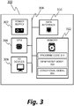
- FIG. 3 shows a computing device 300 configured to implement methods in accordance with the present invention.
- the computing device 300 includes a power supply 304 and a system bus 304.
- the system bus 304 is connected to: a CPU 306; input/output (I/O) devices 308; a data interface 310; and a memory 312.
- the memory 312 holds program code 314, the generative model 202, and the conditional model 204.
- I/O devices 308 include a monitor, a keyboard, and a mouse.
- the data interface 310 is connected one or more sources of image data.
- the computing device 300 is deployed in a hospital or other medical institution and is used by medical professionals to perform deformable registration of medical images.
- computing device 300 may be used to register longitudinal images of cancer patients in order to adjust radiotherapy plans.
- computing device 300 may be used for motion correction of a series of images captured using a medical device.
- Program code 314 may be provided to the medical institution as software.
- program code for performing deformable registration may be integrated within hardware and/or software of a medical device that captures image data.
- deformable registration of medical images may be performed by a remote system or a distributed computing system.
- Figure 4 shows a routine 400 stored within program code 314 which, when executed by the CPU 306, causes the computing device 300 to implement the correspondence determining method 200.
- the generative model 202 and the conditional model 204 are pre-trained prior to the routine 400 being executed, as will be described hereafter.
- the computing device 300 receives, at S402, first image data comprising the source image I S and second image data comprising the reference image I R via the data interface 310.
- the first image data and the second image data are received from the same source, for example from a medical device such as a CT scanner, a PET scanner, or an MRI scanner, or from an image database.
- the first image data and the second image data are received from different sources, for example different medical devices and/or image databases.
- the computing device 300 determines, at S404, an initial deformation field ⁇ 0 , where ⁇ t denotes the deformation field after t iterations of an update routine, as will be described hereafter.
- the initial deformation field ⁇ 0 is determined by randomly sampling from the generative model 202 as will be described hereafter.
- an initial guess of the deformation field may be provided as ⁇ 0 , for example using an existing parametric or a non-parametric deformable registration method.
- the computing device 300 determines, at S406, a change in one or more characteristics of the first deformation field ⁇ 0 .
- determining the change comprises determining gradients of the log probability densities log p ( ⁇ ) and log p ( I R
- I R , I S ) is determined as the sum of the determined gradients of log p ( ⁇ ) and log p ( I R
- ⁇ ⁇ t ; ⁇ t is a step size, which may be fixed or may vary with step number t ; and P is a preconditioning matrix that affects the direction and the size of the change in ⁇ induced by (3).
- Different gradient methods vary from each other by using different step sizes and preconditioning matrices. For ordinary gradient ascent, P is an identity matrix.
- Other examples of gradient methods include the Broyden-Fletcher-Goldfarb-Shanno (BFGS) algorithm and Adam.
- the computing device 300 changes, at S408, characteristics of the first deformation field in accordance with the determined change.
- the optimal deformation field ⁇ * is defined as a deformation field that maximises the posterior probability density of Equation (1).
- the computing device 300 returns, at S410, the converged deformation field ⁇ T , which corresponds to a co-ordinate transformation representing the correspondence between the source image I S and the reference image I R .
- the converged deformation field ⁇ T is applied to the source image I S to determine a transformed source image I S ⁇ ⁇ T .
- the transformed source image may then be compared with the reference image I R , either manually or by a computer program.
- a style transfer operator for translating between two imaging modalities may be applied to the transformed source image or the reference image before comparison.
- FIG. 5 shows an example of a variational autoencoder (VAE) 500 for implementing a generative model in accordance with the present invention.
- the VAE 500 includes an encoder network 502 and a decoder network 504.
- the encoder network 502 is a convolutional deep neural network having convolutional layers and fully-connected layers.
- a parameter vector ⁇ e comprises connection weights between neurons in the encoder network 502.
- the encoder network 502 is configured to receive a deformation field ⁇ as an input, and to output a distribution q ⁇ e ( z
- ⁇ ) is a multivariate normal distribution with mean ⁇ ⁇ e ( ⁇ ) and covariance ⁇ ⁇ e ( ⁇ ) such that q ⁇ e z
- ⁇ N ⁇ ⁇ e ⁇ , ⁇ ⁇ e ⁇ , where the mean ⁇ ⁇ e ( ⁇ ) and the covariance ⁇ ⁇ e ( ⁇ ) are determined by the encoder network 504.
- the decoder network 504 is a deconvolutional deep neural network having fully-connected layers and deconvolutional layers.
- a parameter vector ⁇ d comprises connection weights between neurons in the decoder network 504.
- the decoder network 504 is configured to take a latent variable z as an input, and to output a deterministic function f ⁇ d ( z ) of the latent variable. For a given latent variable z, a given deformation field is associated with a tractable probability density p ⁇ d ( ⁇
- the prior probability density p( ⁇ ) is given by an integral ⁇ p ⁇ d (( ⁇
- the integral for determining p ( ⁇ ) for a given deformation field ⁇ is generally intractable, but can be estimated with the help of the encoder network 502, as will be described in more detail hereafter.
- z ) depends on the squared Euclidian distance between the deformation field ⁇ and the deterministic function f ⁇ d ( z ), for example according to a relation log p ⁇ d ( ⁇
- z ) K - ⁇ ⁇ - f ⁇ d ( z )
- Sampling z from a multivariate normal distribution p z N 0 I , where I is an identity matrix, and passing the sampled z value through the decoder network 504 is equivalent to sampling from the prior probability distribution of deformation fields.
- the computing device 300 determines the initial deformation field ⁇ 0 by sampling from the prior distribution in this way.
- determining a change in one or more characteristics of the deformation field ⁇ t includes determining a gradient of the log prior probability density log p ( ⁇ ) using the generative model 202.
- a variational lower bound of the log prior probability density log p ( ⁇ ) for a given deformation field ⁇ is given by Equation (4): log p ⁇ ⁇ KL q ⁇ e z
- ⁇ E z ⁇ q ⁇ e [ log p ⁇ d ( ⁇
- Equation (4) Equation (4) gives an approximation of the log prior probability density log p ( ⁇ ).
- ⁇ N ⁇ ⁇ e ⁇ , ⁇ ⁇ e ⁇ .
- the deformation field ⁇ t is forward propagated through the encoder network 502, causing the encoder network 502 to output a distribution q ⁇ e ( z
- One or more latent variables are sampled from the distribution q ⁇ e ( z
- An estimated gradient of the variational lower bound with respect to ⁇ is determined from the determined unbiased estimates of the variational lower bounds.
- the gradient of the second term on the right hand side of Equation (4) in the present example is determined by backpropagating the estimated variational lower bound or bounds.
- ⁇ t ) is forward propagated through the decoder network 504 to determine a deterministic function f ⁇ d (z ⁇ ), from which an estimate of the variational lower bound is determined, and this estimate is used for determining an estimated gradient of the log prior probability density with respect to ⁇
- generative models may be implemented using other methods instead of VAEs.
- Examples of other generative models include generative adversarial networks (GANs), Gaussian process models and denoising auto-encoders.
- GANs generative adversarial networks
- Gaussian process models denoising auto-encoders.
- determining a change in one or more characteristics of the deformation field ⁇ t further includes determining a gradient of the log style transfer probability density log p ( I R
- the style transfer probability density is modelled as random noise accounting for image noise and residual changes between the reference image and the transformed source image (for example, residual changes in topology).
- the random noise is assumed to be Gaussian random noise, and hence the conditional model generates a multivariate normal distribution such that p I R
- I S , ⁇ N I S ⁇ ⁇ , ⁇ r 2 I , where the variance ⁇ r 2 is determined from the image data and I is an identity matrix.
- I S , ⁇ K r ⁇ ⁇ I S ⁇ ⁇ ⁇ I R ⁇ 2 / 2 ⁇ r 2 for a constant K r .
- the gradient of the log style transfer probability density with respect to the deformation field ⁇ is determined using this equation.
- the means by which the variance ⁇ r 2 is determined from the image data depends on the modality of the source image and the reference image.
- the variance ⁇ r 2 is matched to the signal to noise ratio (SNR) of the device or devices capturing the images. This may be included, for example, in metadata contained within the image data comprising the source image and/or the reference image.
- the variance ⁇ r 2 is not known a priori and is instead learned from image data as part of a joint optimisation routine.
- the Gaussian noise model described above may be suitable, for example, for monomodal registration of MRI images, which are known to exhibit Gaussian noise.
- the random noise is assumed to take other forms, for example Poisson noise in the case of a CT scan.
- a style transfer operator may be determined for translating the modality of the source image to the modality of the reference image.
- known methods can be used to determine a style transfer operator for translating an image between modalities associated with the different imaging techniques/parameters.
- a known style transfer operator is applied to the source image or the reference image, and the registration process proceeds as monomodal registration.
- the style transfer probability density is modelled using a conditional generative model.
- suitable conditional generative models are those generated by conditional variational autoencoders (CVAEs) and conditional generative adversarial networks (CGANs).
- Figure 6 shows an example of a conditional variational autoencoder (CVAE) 600 for generating a conditional model in accordance with the present invention.
- the CVAE 600 includes an encoder network 602 and a decoder network 604.
- the encoder network 602 is a convolutional deep neural network having a series of convolutional layers connected to a series of fully-connected layers.
- a parameter vector ⁇ e comprises connection weights between neurons in the encoder network 602.
- the encoder network 602 is configured to receive a reference image I R and a transformed source image I S ⁇ ⁇ as inputs, and to output a distribution q ⁇ ⁇ e ( z
- I R ,I S ⁇ ⁇ ) is a multivariate normal distribution with mean ⁇ ⁇ e ( I R ,I S ° ⁇ ) and covariance ⁇ ⁇ e ( I R , I S ⁇ ⁇ ) such that q ⁇ ⁇ e z
- I R , I S ⁇ ⁇ N ⁇ ⁇ ⁇ e I R , I S ⁇ ⁇ , ⁇ ⁇ e I R , I S ⁇ ⁇ , I S ⁇ ⁇ , where the mean ⁇ ⁇ e ( I R ,I S ° ⁇ ) and the covariance ⁇ ⁇ e ( I R , I S ⁇ ⁇ ) are determined by the encoder network 604.
- the decoder network 604 is a deconvolutional deep neural network having fully-connected layers and deconvolutional layers.
- a parameter vector ⁇ d comprises connection weights between neurons in the decoder network 504.
- the decoder network 604 is configured to take a latent variable z, the transformed source image I S ⁇ ⁇ , and the deformation field ⁇ as an input and to output a deterministic function f ⁇ ⁇ d ( z,I S ° ⁇ ) of the latent variable and the transformed source image.
- a given latent variable z a given reference image is associated with a tractable probability density p ⁇ d (I R
- z,I S ⁇ ⁇ ) is assumed to follow an isotropic multivariate normal distribution such that p ⁇ d I R
- z , I S ⁇ ⁇ N f ⁇ ⁇ d z , I S ⁇ ⁇ ), ⁇ 2 I ), where I is an identity matrix and ⁇ 2 is a hyperparameter.
- z,I S , ⁇ ) depends on the squared Euclidian distance between the reference image I R and the deterministic function f ⁇ ⁇ d ( z,I S ⁇ ⁇ ) , for example according to a relation log p ⁇ d ( ⁇
- z ) K ⁇ - ⁇ I R - f ⁇ ⁇ d ( z,I S ⁇ ⁇ ) ⁇ 2 /(2 ⁇ 2 ) for a constant K ⁇ .
- Sampling z from a multivariate normal distribution p z N 0 I , where I is an identity matrix, and passing the sampled z value through the decoder network 604 along with the source image I S and the deformation field ⁇ is equivalent to sampling from the style transfer probability distribution of reference images, given the source image I S and the deformation field ⁇ .
- determining a change in one or more characteristics of the deformation field ⁇ t includes determining a gradient of the log style transfer probability density log p (I R
- I S , ⁇ ) is given by Equation (5): log p I R
- I R , I S ⁇ ⁇ E z ⁇ q ⁇ ⁇ e log p ⁇ d I R
- Equation (5) Since the KL divergence is strictly non-negative, the left hand side of Equation (5) is a lower bound to log p ( I R
- I R , I S ⁇ ⁇ N ⁇ ⁇ ⁇ e I R , I S ⁇ ⁇ , ⁇ ⁇ e I R , I S ⁇ ⁇ .
- the reference image I R and the transformed source image I S ⁇ ⁇ t are forward propagated through the encoder network 602, causing the encoder network 602 to output a distribution q ⁇ ⁇ e (z
- One or more latent variables are sampled from the distribution q ⁇ ⁇ e ( z
- An estimated gradient of the variational lower bound with respect to I s ⁇ ⁇ , and hence an estimated gradient of the log style transfer probability density with respect to I s ° ⁇ , is determined from the determined unbiased estimates of the variational lower bounds.
- the gradient of the second term on the right hand side of Equation (4) in the present example is determined by backpropagating the estimated variational lower bound or bounds through the CVAE 600. Since the transformed source image I s ⁇ ⁇ is a differentiable function of the deformation field ⁇ , the gradient of the variational lower bound with respect to the deformation field is readily determined from the gradient of the variational lower bound with respect to the transformed source image (this may, for example, involve further backpropagation of the variational lower bound).
- I R , I S ⁇ ⁇ ) is forward propagated through the decoder network 604 to determine a deterministic function f ⁇ ⁇ d (z ⁇ ,I S ⁇ ⁇ ), from which an estimate of the variational lower bound is determined, and this estimate is used for determining an estimated gradient of the log style transfer probability density with respect to ⁇ .
- the generative model 202 and the conditional model 204 are pre-trained prior to the correspondence determining method 200 being implemented.
- synthetic deformation fields are used to pre-train the VAE 500.
- the synthetic deformation fields are chosen to cover, as best as possible, the expected deformations of a target object of interest.
- Synthetic deformation fields may be generated, for example, using a parametric model (such as a spline model or a mesh-based model) of a target object (such as an organ in a medical application).
- examples of the present invention further include refining the generative model using real data, as will be described in detail hereafter, such that even for a small and/or inaccurate initial set of synthetic deformation fields, the prior distribution will improve as more real image data is received and eventually yield accurate results.
- Pre-training the VAE 500 using synthetic deformation fields is performed using stochastic gradient ascent, in which each synthetic deformation field is forward propagated through the VAE 500 in order to determine one or more (unbiased) estimated variational lower bounds as given by Equation (4) for each synthetic deformation field.
- Each estimated variational lower bound is backpropagated through the VAE 500 to determine a gradient of the estimated variational lower bound with respect to the parameters ⁇ e , ⁇ d .
- Gradient ascent is performed with respect to each estimated variational lower bound, and performing this for a large number of estimated variational bounds and a large number of synthetic deformation fields results in stochastic optimisation of the variational lower bound, and thus causes the decoder network 502 of the VAE 500 to approximate the distribution of synthetic deformation fields, which is then used to determine the prior probability density p ( ⁇ ) for a given deformation field.
- the conditional model 204 is implemented using the CVAE 600
- the CVAE 600 is pre-trained using pairs of registered images having different modalities.
- a generative model corresponding to a prior probability distribution of deformation fields is refined using the results of the deformable registration process. In this way, the generative model more accurately approximates the prior distribution of deformation fields as more image pairs are registered.
- Figure 7 shows a correspondence determining method 700, which is an example of the correspondence determining method 200 described above, and employs, in addition to the generative model 202, the conditional model 204, and the deformation field update routine 206, a parameter update routine 208 for updating parameters of the generative model 202.
- a converged deformation field, ⁇ T i is determined, for example using the routine 400, and the parameter update routine updates parameters of the generative model 202 using the determined converged deformation field ⁇ T i .
- One such method involves, for each converged deformation field ⁇ T i , updating parameters of the generative model 202, to optimise the prior probability density p ⁇ T i with respect to the parameters of the generative model 202.
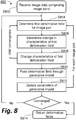
- Figure 8 shows an exemplary routine 800, which, when executed by a computing device, causes the computing device to perform the correspondence determining method 700.
- the computing device receives, at S802, the image data comprising the set of pairs I S i I R i of source images and reference images. For each image pair, the computing device determines, at S804, a respective initial deformation field ⁇ 0 i .
- determining an initial deformation field may involve sampling from the generative model 202, or may include receiving an initial guess of the deformation field.
- the computing device determines, at S806, a change in one or more characteristics of the respective deformation field ⁇ 0 i .
- the change in characteristics is determined using an equivalent process to that described above with reference to Figure 4 .
- the computing device changes, at S808, characteristics of the respective deformation field in accordance with the determined change.
- the converged deformation field ⁇ T i represents a first estimate of the correspondence between the source image I S i and the reference image ⁇ R i .
- the computing device passes, at S810, each converged deformation field ⁇ T i through the generative model 202, and updates, at S812, parameters of the generative model 202, to optimise the prior probability density with the respect to the parameters of the generative model.
- parameters of the VAE 500 are updated to optimise the variational lower bound of the log prior probability density given by Equation (4) above.
- the converged deformation field ⁇ T i is forward propagated through the encoder network 502, causing the encoder network 502 to output a distribution q ⁇ e z
- One or more latent variables are sampled from the distribution q ⁇ e z
- An estimated gradient of the variational lower bound with respect to ⁇ e , ⁇ d , and hence an estimated gradient of the log prior probability density log p ⁇ T i with respect to ⁇ e , ⁇ d is determined by backpropagating the estimated variational lower bound or bounds through the VAE 500.
- a gradient-based update rule is applied to update the parameters ⁇ e , ⁇ d .
- the variational lower bound is optimised with respect to the parameters ⁇ e , ⁇ d , and hence the prior probability density p ⁇ T i is optimised (indirectly) with respect to the parameters ⁇ e , ⁇ d .
- ⁇ T i is forward propagated through the decoder network 504 to determine a deterministic function f ⁇ d (z ⁇ ), from which an estimate of the variational lower bound is determined.
- the estimated variational bound is then backpropagated to determine the approximate gradient of log p ⁇ T i with respect to ⁇ e , ⁇ d and a gradient-based update rule is used to update the parameters ⁇ e , ⁇ d based on this approximate gradient.
- the routine 800 Having updated the parameters of the generative model 202 using each first estimate ⁇ T i corresponding to each image pair, the routine 800 returns to S804.
- S804-S812 are performed iteratively.
- the computing device determines, for each image pair, a new estimate of the deformation field, and uses the new estimate to update the parameters of the generative model. This iterative process continues until predefined convergence conditions are satisfied.
- the predefined convergence conditions may be based on the estimated deformation fields, the parameters of the generative model, or a combination of both. Suitable convergence criteria for gradient-based optimisation methods will be well-known to those skilled in the art.
- the computing device returns, at S814, the converged deformation fields, which each encodes co-ordinate transformation representing a correspondence between each source images I S i and corresponding reference image I R i .
- the same computing device is used to register pairs of images and to update parameters of the generative model 202 using the registered pairs.
- the computing device updates parameters in parallel with registering images.
- updating the parameters of the generative model 202 is performed by a separate computing device.
- a deployed computing device/system may perform deformable registration on a set of images, and send the resulting deformation fields to a training device/system, which uses the images to determine updated parameters for the deployed computing device/system. This arrangement may be particularly relevant for medical applications, for reason explained hereafter.
- a similar iterative process to that described above for updating the parameters of the generative model 202 is also applied to update parameters of the conditional model 204.
- each converged deformation field is passed through the conditional model 204, and the parameters of the conditional model are updated to optimise the style transfer probability density with respect to the parameters of the conditional model 204.
- updating the parameters of the conditional model 204 is performed after each iteration of updating the deformation field and the parameters of the generative model 202.
- the parameters and the deformation field are updated in a different order.
- a single joint optimisation step is performed in which the deformation field, the parameters of the generative model 202, and the parameters of the conditional model 204, are updated together to optimise the posterior probability density p ⁇ T i
- Some examples of the present invention include alternative or further steps to refine the generative model and/or the conditional model, or to otherwise improve the accuracy of the determined correspondence.
- a source image I S is registered to a reference image I R using the method described herein, yielding a first converged deformation field f .
- the same reference image I R is registered to the same source image I S , yielding a second converged deformation field g .
- the second deformation field g should be the inverse of the first deformation field f .
- an error associated with the composition f ⁇ g, and an identity field Id (corresponding to an identity co-ordinate transformation) is backpropagated through the generative model and/or the conditional model, and a gradient-based optimisation method is then used to update parameters of the generative model and/or the conditional model such that the error is minimised.
- the error associated with the composition f ⁇ g and an identity field Id is given by an L 2 norm ⁇ f ⁇ g - Id ⁇ L 2 .
- backpropagating a loss given by ⁇ v f + ⁇ v g ⁇ L 2 through the generative model and/or the conditional model, and updating the parameters of the generative model and/or the conditional model to minimise the loss has an inertial effect that encourages the method to generate diffeomorphic deformation fields.
- Updating parameters of the generative model and/or the conditional model using image data as described above results in the prior probability distribution and/or the conditional probability distribution more accurately reflecting the data as the method is performed.
- the models may become highly accurate even in cases where the generative model and/or the conditional model were poorly pre-trained, for example due to a lack of ground-truth data or sufficiently accurate synthetic data.
- devices are subject to regulatory approval and may only be deployed after such approval is granted.
- the performance of a device implementing the deformable registration process would be tested for a fixed set of model parameters, and that updating these model parameters in a deployed device (or equivalently, updating model parameters in a remote system in the case of a network-based implementation) may result in the regulatory approval no longer being valid. It is therefore suggested that parameters of a deployed system/device would be frozen, such that the deployed system/device performs image registration without updating the parameters.
- Image data sent to the deployed system/device would simultaneously be sent to a secondary system/device that "mirrors" the deployed system/device.
- Parameters of the secondary system/device would be updated using the methods described above, and hence the performance of the secondary system/device would be expected to improve over time, but the output of the secondary device would never be used for the intended purpose of the deployed device (for example, making clinical decisions in the case of a medical application).
- regulatory approval would be sought for the secondary system/device, and if granted, the updated parameters of the secondary system/device would be imported to the deployed system/device. This process of updating and seeking regulatory approval could be performed periodically, for example.
- the present invention provides an accurate and widely-applicable method of performing deformable registration.
- Some examples of the present invention include an additional process in which supervised learning model is used to train a one-shot model, such that the one-shot model may subsequently be used to determine approximations of converged deformation fields resulting from the variational method described above.
- the one-shot model is a regression network.
- other one-shot models may be used, for example support vector machines (SVMs).
- SVMs support vector machines
- a one-shot method takes a source image and a reference image as inputs, and outputs an approximation of the converged deformation field that would result from the application of the variational method described above to the same source image and reference image.
- Determining an approximation of a converged deformation field using the one-shot model may result in a significant time saving compared with determining a converged deformation field using the variational method, and if one-shot model is sufficiently well-trained, may suffer only a very slight loss of accuracy compared with the variational method.
- the regression network may be any suitable neural network, for example a convolutional neural network (CNN) configured for regression.
- CNN convolutional neural network
- a method of training the regression network includes forward propagating a source image and a reference image through the network, to determine a first approximation of the converged deformation field corresponding to the source image and the reference image. The method continues by determining an error associated with the first approximation and the converged deformation field determined using the variational method.
- the error is a mean-squared difference between the first approximation and the converged deformation field, but other suitable metrics for quantifying a difference between two deformation fields may be used in other examples.
- the determined error is backpropagated through the regression network, to determine gradients of the determined error with respect to parameters of the regression network.
- the parameters of the regression network are updated using a gradient-based update rule, whereby to reduce the error associated with the first approximation and the converged deformation field.
- the parameters are iteratively updated in this way until predetermined convergence criteria are satisfied.
- the training process is repeated for a large number of source images, reference images, and corresponding converged deformation fields, such that the regression network learns how to determine deformation fields for unregistered pairs of source images and reference images.
- the one-shot model may be trained in parallel to the updating of parameters of the generative and/or conditional models used in the variational method.
- partially-converged deformation field as opposed to, or as well as, converged deformation fields, may be used to train the one-shot model.
- reinforcement learning may be used to train an autonomous agent to determine approximations of converged deformation fields resulting from the variational method.
- an approximation of a deformation field is associated with a policy of the autonomous agent.
- the policy is updated according to a predetermined reward structure, such that higher (conventionally, though not necessarily, more positive) rewards are associated with actions that reduce an error associated with the approximation and the converged deformation field resulting from the variational method.
Landscapes
- Engineering & Computer Science (AREA)
- Theoretical Computer Science (AREA)
- Physics & Mathematics (AREA)
- General Physics & Mathematics (AREA)
- Software Systems (AREA)
- Data Mining & Analysis (AREA)
- Computer Vision & Pattern Recognition (AREA)
- Artificial Intelligence (AREA)
- Mathematical Physics (AREA)
- Evolutionary Computation (AREA)
- General Engineering & Computer Science (AREA)
- Computing Systems (AREA)
- Life Sciences & Earth Sciences (AREA)
- Evolutionary Biology (AREA)
- Bioinformatics & Computational Biology (AREA)
- Bioinformatics & Cheminformatics (AREA)
- General Health & Medical Sciences (AREA)
- Probability & Statistics with Applications (AREA)
- Medical Informatics (AREA)
- Databases & Information Systems (AREA)
- Health & Medical Sciences (AREA)
- Mathematical Optimization (AREA)
- Computational Linguistics (AREA)
- Computational Mathematics (AREA)
- Mathematical Analysis (AREA)
- Pure & Applied Mathematics (AREA)
- Multimedia (AREA)
- Operations Research (AREA)
- Algebra (AREA)
- Biomedical Technology (AREA)
- Biophysics (AREA)
- Molecular Biology (AREA)
- Image Analysis (AREA)
- Image Processing (AREA)
Abstract
Description
- The present disclosure relates to a method for determining a correspondence between a source image and a reference image.
- Deformable image registration aims to find correspondence between pairs of images. In medicine, deformable image registration has a wide range of applications both in diagnosis and in therapy. For example, in the field of oncology, longitudinal images of the same patient are often acquired to monitor the progression of a tumour and to plan radiation therapy. In some examples, a radiation therapy plan is updated automatically depending on the progression of the tumour. Deformable registration of the longitudinal images corrects for differences in aspect, as well as deformations of the patient's body surrounding the tumour, for example caused by weight gain/loss, breathing, and/or other movements, allowing for efficient visualisation and comparison of the images, either manually or automatically.
- Other applications of deformable image registration include motion correction, in which a series of images of a continuously/continually moving/deforming target are captured one after another (for example, as frames of a video), in which case deformable image registration corrects for the continuous/continual moving/deforming tissue to allow residual changes to the target to be identified. Further examples include deformable registration of images of corresponding anatomies of multiple patients, allowing for abnormalities in one or more of the anatomies to be identified or segment organs using an atlas image.
- Deformable image registration involves determining a deformation field representing a correspondence between a source image and a reference image. Since the deformation field is typically high-dimensional and mathematically ill-defined, it needs to be heavily regularised. Existing methods include parametric approaches in which a model of the deformation field is controlled by a relatively small number of control points or parameters based on prior knowledge of possible deformations. Such methods are often unable to model complex deformations accurately, for example those exhibited by parts of the human anatomy.
- Existing methods further include regularization of an energy computed on, for example, a Jacobian, Hessian, or Laplacian of the deformation field. Such methods can result in over-smoothed/over-regularised deformation fields and/or deformations fields that do not represent realistic deformations due to a lack of high-level prior knowledge of possible deformations.
- Finally, deformable image registration typically involves the optimization of a high-dimensional functional. Iterative optimization procedure are most commonly used, leading to time-consuming algorithms that require minutes or more to compute.
- According to various aspects of the present invention, there are provided methods and apparatus for determining a correspondence between a source image and a reference image, in accordance with the appended claims.
- Further features and advantages of the invention will become apparent from the following description of preferred embodiments of the invention, given by way of example only, which is made with reference to the accompanying drawings.
-
-
Figure 1 shows a deformable registration of a source image to a reference image. -
Figure 2 is a schematic diagram of a method for determining a deformation field. -
Figure 3 is a flow diagram of a routine for determining a deformation field. -
Figure 4 is a schematic diagram of a variational autoencoder (VAE). -
Figure 5 is a schematic diagram of a routine for determining a deformation field and refining a generative model. -
Figure 6 is a schematic diagram of a conditional variational autoencoder (CVAE). -
Figure 7 is a flow diagram of a routine for determining a set of deformation fields. -
Figure 8 is a block diagram of a computing device for registering a source image to a reference image. - In the present disclosure, an image is, for example, a set of digital data mapping a two- or three-dimensional domain to one or more real numbers, each of the real numbers associating an intensity with a voxel/pixel within the image domain. The term "image" may refer either to the data itself, or to a visual representation of the data when rendered using, for example, a screen or a projector.
- Images may be captured using various imaging techniques including, for example, digital photography, magnetic resonance imaging (MRI), X-ray fluoroscopy, proton emission tomography (PET), echography, and computerised tomography (CT). Images captured using the same imaging technique may use different imaging parameters. For example, MRI may be parameterised as T1 weighted or T2 weighted. A given imaging technique using given imaging parameters is referred to as an imaging modality.
- A deformation field is a mapping that transforms a co-ordinate system of an image. Deformation fields are expressed differently depending on the deformation model being used. In some examples, a deformation field is represented by a pixel-to-vector mapping or a voxel-to-vector mapping, associating a displacement vector with each pixel/voxel of the image.
-
Figure 1a shows a two-dimensional reference image 100 containing three objects: atriangle 102, acircle 104, and adie 106. Thereference image 100 has an associated Cartesian co-ordinate system, represented by aCartesian grid 108. Thereference image 100 was captured at a first time. -
Figure 1b shows a two-dimensional source image 110, similarly containing three objects: atriangle 112, acircle 114, and adie 116. Thesource image 110 has an associated Cartesian co-ordinate system, represented by aCartesian grid 118. In this example, thesource image 110 was captured at a second time, using the same imaging modality as that of thereference image 100. It is observed that, while thetriangle 112 and thecircle 114 appear to correspond to thetriangle 102 and thecircle 104, thedie 116 appears warped compared with thedie 106. - The present invention provides a method of determining a correspondence between the
source image 110 and thereference image 100. The correspondence is represented by a deformation field φ, which encodes a co-ordinate transformation that may be applied to theCartesian grid 118 of thesource image 110.Figure 1c shows atransformed source image 120, which is the result of applying the deformation field φ to thesource image 110. Thetransformed source image 120 contains atriangle 122, acircle 124, and adie 126. Thetransformed source image 120 has a transformed co-ordinate system, represented by atransformed grid 128. In this example, the deformation field φ is non-uniform, and accordingly different regions of thesource image 100 are deformed differently to arrive at thetransformed source image 120. As observed in the present example, features within the source image move as a result of the source image being transformed. For this reason, source images are sometimes referred to as moving images, whereas reference images are sometimes referred to as fixed images. - It is observed that the
transformed source image 120 approximately corresponds to thereference image 100. In particular, the die 126 of thetransformed source image 120 appears to correspond approximately to the die 106 of thereference image 100. However, closely comparing thereference image 100 with thetransformed source image 120 reveals that a central spot on thedie 126 appears in a different position to a corresponding central spot on the die 106. This difference is residual to the co-ordinate transformation encoded by the deformation field φ, suggesting that in the interval between the first time and the second time, the central spot has moved relative to its surrounding region. Comparing thereference image 100 with the transformed source image could be performed manually, for example by overlaying the transformed source image on top of the reference image, or alternatively could be performed automatically by a computer. - In medical applications, differences that are residual to a co-ordinate transformation between a source image and a reference image are often of interest. In the field of oncology, for example, the growth or change of a tumour is residual to deformations in the surrounding tissue of a patient's body.
- As mentioned above, the
reference image 100 and thesource image 110 have the same modality. Determining a correspondence between thesource image 110 and thereference image 100 is therefore referred to as monomodal registration. In other examples, a source image and a reference image are captured using different modalities, and determining a correspondence between the source image and the reference image is referred to as multimodal registration. The present invention is applicable both to monomodal registration and to multimodal registration, as will be described in detail hereafter. - As shown in
Figure 2 , an exemplarycorrespondence determining method 200 for determining a correspondence between a source image I S and a reference image I R employs agenerative model 202, aconditional model 204, and anupdate routine 206. Thegenerative model 202 corresponds to a prior probability distribution of deformation fields, each deformation field corresponding to a respective co-ordinate transformation. The prior probability distribution represents the expected distribution of deformation fields, given the particular application to which the deformable registration method is being applied. For example, in a medical application a particular organ may be expected to deform in a particular way when a patient breathes. Deformation fields consistent with this expected deformation would have a higher probability in the prior probability distribution than other arbitrary deformation fields. - For a given source image and a given deformation field, the
conditional model 204 generates a style transfer probability distribution of reference images. A style transfer probability density p(I R|I S,φ) associated with the reference image I R, given the source image I S and the deformation field φ, can be estimated using theconditional model 204, as will be described hereafter with reference to two exemplary conditional models. - Given the prior probability density p(φ) and the style transfer probability density p(I R|I S,φ), a posterior probability density p(φ|I R,I S) can be determined in principle using Bayes' theorem in the form of Equation (1):

- The present method involves determining a deformation field that maximises the posterior probability density p(φ|I R,I S). The determined deformation field represents a best estimate of the correspondence between the source image I S and the reference image I R. It is noted that the probability densities p(I S) and p(I R ,I S ) are independent of the deformation field φ, and hence the dependence of the posterior probability density p(φ|I R,IS ) on φ is entirely due to the dependence of the prior probability distribution p(φ) and the style transfer probability distribution p(φ|I R,IS ) on φ. Taking a logarithm of Equation (1) leads to Equation (2):

- The
update routine 206 updates the deformation field φ to increase the sum of log probability densities given by Equation (2), thereby also increasing the posterior probability density given by Equation (1). In this example, updating the first deformation field includes determining, from thegenerative model 202 and theconditional model 204, a gradient with respect to φ of the log posterior probability density given by Equation (2). - The above process is repeated iteratively until predetermined convergence criteria are satisfied, resulting in a converged deformation field that represents the correspondence between the source image I S and the reference image I R.
-
Figure 3 shows acomputing device 300 configured to implement methods in accordance with the present invention. Thecomputing device 300 includes apower supply 304 and asystem bus 304. Thesystem bus 304 is connected to: aCPU 306; input/output (I/O)devices 308; adata interface 310; and amemory 312. Thememory 312 holdsprogram code 314, thegenerative model 202, and theconditional model 204. In this example, I/O devices 308 include a monitor, a keyboard, and a mouse. The data interface 310 is connected one or more sources of image data. - In an example, the
computing device 300 is deployed in a hospital or other medical institution and is used by medical professionals to perform deformable registration of medical images. For example,computing device 300 may be used to register longitudinal images of cancer patients in order to adjust radiotherapy plans. Alternatively or additionally,computing device 300 may be used for motion correction of a series of images captured using a medical device.Program code 314 may be provided to the medical institution as software. In some examples, program code for performing deformable registration may be integrated within hardware and/or software of a medical device that captures image data. In other examples, deformable registration of medical images may be performed by a remote system or a distributed computing system. -
Figure 4 shows a routine 400 stored withinprogram code 314 which, when executed by theCPU 306, causes thecomputing device 300 to implement thecorrespondence determining method 200. Thegenerative model 202 and theconditional model 204 are pre-trained prior to the routine 400 being executed, as will be described hereafter. Thecomputing device 300 receives, at S402, first image data comprising the source image I S and second image data comprising the reference image I R via thedata interface 310. In some examples, the first image data and the second image data are received from the same source, for example from a medical device such as a CT scanner, a PET scanner, or an MRI scanner, or from an image database. In other examples, the first image data and the second image data are received from different sources, for example different medical devices and/or image databases. - The
computing device 300 determines, at S404, an initial deformation field φ 0, where φt denotes the deformation field after t iterations of an update routine, as will be described hereafter. In this example, the initial deformation field φ 0 is determined by randomly sampling from thegenerative model 202 as will be described hereafter. In other examples, an initial guess of the deformation field may be provided as φ 0, for example using an existing parametric or a non-parametric deformable registration method. - The
computing device 300 determines, at S406, a change in one or more characteristics of the first deformation field φ 0. In this example, determining the change comprises determining gradients of the log probability densities logp(φ) and logp(I R|IS,φ) respectively. A gradient of logp(φ|IR,I S) is determined as the sum of the determined gradients of logp(φ) and logp(I R|I S,φ), in accordance with Equation (2). The change in characteristics is determined according to a gradient-based update rule, as shown by the Equation (3):
- The
computing device 300 changes, at S408, characteristics of the first deformation field in accordance with the determined change. The process of determining a change and changing the characteristics in accordance with the determined change is repeated iteratively, resulting in a sequence of deformation fields
- The
computing device 300 returns, at S410, the converged deformation field φT, which corresponds to a co-ordinate transformation representing the correspondence between the source image I S and the reference image I R. - In some examples of the present invention, the converged deformation field φT is applied to the source image I S to determine a transformed source image I S ∘ φT . For monomodal registration, the transformed source image may then be compared with the reference image I R, either manually or by a computer program. For multimodal registration, a style transfer operator for translating between two imaging modalities may be applied to the transformed source image or the reference image before comparison.
-
Figure 5 shows an example of a variational autoencoder (VAE) 500 for implementing a generative model in accordance with the present invention. TheVAE 500 includes anencoder network 502 and adecoder network 504. Theencoder network 502 is a convolutional deep neural network having convolutional layers and fully-connected layers. A parameter vector θ e comprises connection weights between neurons in theencoder network 502. Theencoder network 502 is configured to receive a deformation field φ as an input, and to output a distribution qθe (z|φ) of latent variables z. In this example, qθe (z|φ) is a multivariate normal distribution with mean µ θ e (φ) and covariance ∑θe (φ) such that
e (φ) and the covariance ∑θe (φ) are determined by theencoder network 504. - The
decoder network 504 is a deconvolutional deep neural network having fully-connected layers and deconvolutional layers. A parameter vector θd comprises connection weights between neurons in thedecoder network 504. Thedecoder network 504 is configured to take a latent variable z as an input, and to output a deterministic function fθd (z) of the latent variable. For a given latent variable z, a given deformation field is associated with a tractable probability density pθd (φ|z). The prior probability density p(φ) is given by an integral ∫pθd ((φ|z)p(z)dz, where p(z) is a probability density of the latent variables. The integral for determining p(φ) for a given deformation field φ is generally intractable, but can be estimated with the help of theencoder network 502, as will be described in more detail hereafter. - In the present example, pθ
d (φ|z) is assumed to follow an isotropic multivariate normal distribution such that
d (φ|z) depends on the squared Euclidian distance between the deformation field φ and the deterministic function fθd (z), for example according to a relation log pθd (φ|z) = K - ∥φ - fθd (z)||2/(2σ2 ) for a constant K. - Sampling z from a multivariate normal distribution

decoder network 504 is equivalent to sampling from the prior probability distribution of deformation fields. In the example discussed above in which thegenerative model 202 is implemented using theVAE 500, thecomputing device 300 determines the initial deformation field φ 0 by sampling from the prior distribution in this way. - As discussed above, determining a change in one or more characteristics of the deformation field φ t includes determining a gradient of the log prior probability density logp(φ) using the
generative model 202. In the case that thegenerative model 202 is implemented using theVAE 500, a variational lower bound of the log prior probability density logp(φ) for a given deformation field φ is given by Equation (4):
- where KL denotes the Kullback-Leibler divergence between two distributions. Since the KL divergence is strictly non-negative, the left hand side of Equation (4) is a lower bound to logp(φ). Furthermore, for a sufficiently well-trained
encoder network 502, the KL divergence term on the left hand side will be close to zero, and hence Equation (4) gives an approximation of the log prior probability density logp(φ). The first term on right hand side of Equation (4) is tractable by sampling, while the KL term on the right hand side is given in closed form for the multivariate normal distributions

- In the present example, in order to determine the gradient of logp(φ) with respect to the deformation field φ, the deformation field φ t is forward propagated through the
encoder network 502, causing theencoder network 502 to output a distribution qθe (z|φt ) of latent variables associated with the deformation field φt . One or more latent variables are sampled from the distribution qθe (z|φt ) and forward propagated through thedecoder network 504, which outputs deterministic functions fθd (z) of the one or more sampled latent variables, from which one or more unbiased estimates of the variational lower bound of Equation (4) are determined. An estimated gradient of the variational lower bound with respect to φ, and hence an estimated gradient of the log prior probability density with respect to φ, is determined from the determined unbiased estimates of the variational lower bounds. The gradient of the second term on the right hand side of Equation (4) in the present example is determined by backpropagating the estimated variational lower bound or bounds. In a further example, the mean value zµ of the distribution qθe (z|φt ) is forward propagated through thedecoder network 504 to determine a deterministic function f θ d (z µ ), from which an estimate of the variational lower bound is determined, and this estimate is used for determining an estimated gradient of the log prior probability density with respect to φ - For the present invention, generative models may be implemented using other methods instead of VAEs. Examples of other generative models include generative adversarial networks (GANs), Gaussian process models and denoising auto-encoders.
- As discussed above, determining a change in one or more characteristics of the deformation field φt further includes determining a gradient of the log style transfer probability density logp(I R|I S,φ) using the
conditional model 204. In an example of monomodal registration, the style transfer probability density is modelled as random noise accounting for image noise and residual changes between the reference image and the transformed source image (for example, residual changes in topology). - In one example, the random noise is assumed to be Gaussian random noise, and hence the conditional model generates a multivariate normal distribution such that


- The Gaussian noise model described above may be suitable, for example, for monomodal registration of MRI images, which are known to exhibit Gaussian noise. In other examples of monomodal registration, the random noise is assumed to take other forms, for example Poisson noise in the case of a CT scan.
- In some examples of multimodal registration, a style transfer operator may be determined for translating the modality of the source image to the modality of the reference image. By imaging identical objects using two modalities, known methods can be used to determine a style transfer operator for translating an image between modalities associated with the different imaging techniques/parameters. In some examples, a known style transfer operator is applied to the source image or the reference image, and the registration process proceeds as monomodal registration.
- In some examples of multimodal registration, the style transfer probability density is modelled using a conditional generative model. Examples of suitable conditional generative models are those generated by conditional variational autoencoders (CVAEs) and conditional generative adversarial networks (CGANs).
Figure 6 shows an example of a conditional variational autoencoder (CVAE) 600 for generating a conditional model in accordance with the present invention. TheCVAE 600 includes anencoder network 602 and adecoder network 604. Theencoder network 602 is a convolutional deep neural network having a series of convolutional layers connected to a series of fully-connected layers. A parameter vector ρ e comprises connection weights between neurons in theencoder network 602. Theencoder network 602 is configured to receive a reference image I R and a transformed source image I S ∘ φ as inputs, and to output a distribution q̃ρe (z|IR,IS ° φ) of latent variables z. In this example, q̃ρe (z|IR,IS ∘ φ) is a multivariate normal distribution with mean µ̃ρe (IR,IS ° φ) and covariance ∑̃ ρe (I R,I S ∘ φ) such that
e (IR,IS ° φ) and the covariance ∑̃ ρe (I R,I S ∘ φ) are determined by theencoder network 604. - The
decoder network 604 is a deconvolutional deep neural network having fully-connected layers and deconvolutional layers. A parameter vector ρ d comprises connection weights between neurons in thedecoder network 504. Thedecoder network 604 is configured to take a latent variable z, the transformed source image I S ∘ φ, and the deformation field φ as an input and to output a deterministic function f̃ρd (z,IS ° φ) of the latent variable and the transformed source image. For a given latent variable z, a given reference image is associated with a tractable probability density pθd (IR |z, IS ∘ φ). In the present example, pθd (IR |z,IS ∘ φ) is assumed to follow an isotropic multivariate normal distribution such that
d (IR |z,IS,φ) depends on the squared Euclidian distance between the reference image I R and the deterministic function f̃ρd (z,IS ∘ φ), for example according to a relation logpθd (φ|z) = K̃ -∥I R - f̃ρd (z,IS ∘ φ)∥2/(2σ̃2) for a constant K̃. - Sampling z from a multivariate normal distribution

decoder network 604 along with the source image I S and the deformation field φ is equivalent to sampling from the style transfer probability distribution of reference images, given the source image I S and the deformation field φ. - As discussed above, determining a change in one or more characteristics of the deformation field φ t includes determining a gradient of the log style transfer probability density logp(IR|I S,φ) using the
conditional model 204. For a given deformation field φ, a variational lower bound of the style transfer prior probability density logp(IR|I S,φ) is given by Equation (5):
- Since the KL divergence is strictly non-negative, the left hand side of Equation (5) is a lower bound to logp(I R|I S, φ). Furthermore, for a sufficiently well-trained
encoder network 602, the KL divergence term on the left hand side will be close to zero, and hence Equation (5) gives an approximation of the style transfer probability density logp(I R|I S, φ). The first term on right hand side of Equation (5) is tractable by sampling, while the KL term on the right hand side is given in closed form for the multivariate normal distributions

- In the present example, the reference image I R and the transformed source image IS ∘ φt are forward propagated through the
encoder network 602, causing theencoder network 602 to output a distribution q̃ρe (z|IR, IS ∘ φt ) of latent variables. One or more latent variables are sampled from the distribution q̃ ρe (z|IR,IS ∘ φt )and forward propagated through thedecoder network 604 along with the transformed source image I S ∘ φt, and thedecoder network 604 outputs deterministic functions f̃ρd (z,IS ∘ φ) of the one or more sampled latent variables, from which one or more unbiased estimates of the variational lower bound are determined. An estimated gradient of the variational lower bound with respect to Is ∘ φ, and hence an estimated gradient of the log style transfer probability density with respect to Is ° φ, is determined from the determined unbiased estimates of the variational lower bounds. The gradient of the second term on the right hand side of Equation (4) in the present example is determined by backpropagating the estimated variational lower bound or bounds through theCVAE 600. Since the transformed source image Is ∘ φ is a differentiable function of the deformation field φ, the gradient of the variational lower bound with respect to the deformation field is readily determined from the gradient of the variational lower bound with respect to the transformed source image (this may, for example, involve further backpropagation of the variational lower bound). In a further example, the mean value zµ of the distribution q̃ρe (z|I R , I S ∘ φ) is forward propagated through thedecoder network 604 to determine a deterministic function f̃ρd (zµ,IS ∘ φ), from which an estimate of the variational lower bound is determined, and this estimate is used for determining an estimated gradient of the log style transfer probability density with respect to φ. - In a further example in which a CVAE is used for generating a conditional model, the ordering of the inputs and conditioning in the CVAE is reversed from that shown in
Figure 6 . As a result, the encoder network takes the deformation field as an input, and both the encoder and decoder network are conditioned on the source image and the reference image. Other arrangements are envisaged without departing from the scope of the invention. - In the example discussed above with reference to
Figure 2 , thegenerative model 202 and theconditional model 204 are pre-trained prior to thecorrespondence determining method 200 being implemented. In an example in which thegenerative model 202 is implemented using theVAE 500, synthetic deformation fields are used to pre-train theVAE 500. The synthetic deformation fields are chosen to cover, as best as possible, the expected deformations of a target object of interest. Synthetic deformation fields may be generated, for example, using a parametric model (such as a spline model or a mesh-based model) of a target object (such as an organ in a medical application). Although the synthetic deformation fields used to pre-train thegenerative model 202 will affect the performance of the deformable registration process, examples of the present invention further include refining the generative model using real data, as will be described in detail hereafter, such that even for a small and/or inaccurate initial set of synthetic deformation fields, the prior distribution will improve as more real image data is received and eventually yield accurate results. - Pre-training the
VAE 500 using synthetic deformation fields is performed using stochastic gradient ascent, in which each synthetic deformation field is forward propagated through theVAE 500 in order to determine one or more (unbiased) estimated variational lower bounds as given by Equation (4) for each synthetic deformation field. Each estimated variational lower bound is backpropagated through theVAE 500 to determine a gradient of the estimated variational lower bound with respect to the parameters θe , θd . Gradient ascent is performed with respect to each estimated variational lower bound, and performing this for a large number of estimated variational bounds and a large number of synthetic deformation fields results in stochastic optimisation of the variational lower bound, and thus causes thedecoder network 502 of theVAE 500 to approximate the distribution of synthetic deformation fields, which is then used to determine the prior probability density p(φ) for a given deformation field. In an example in which theconditional model 204 is implemented using theCVAE 600, theCVAE 600 is pre-trained using pairs of registered images having different modalities. - In some examples of the present invention, a generative model corresponding to a prior probability distribution of deformation fields is refined using the results of the deformable registration process. In this way, the generative model more accurately approximates the prior distribution of deformation fields as more image pairs are registered.
-
Figure 7 shows acorrespondence determining method 700, which is an example of thecorrespondence determining method 200 described above, and employs, in addition to thegenerative model 202, theconditional model 204, and the deformationfield update routine 206, aparameter update routine 208 for updating parameters of thegenerative model 202. In this example, the image data includes a set of pairs

generative model 202 using the determined converged deformation field

generative model 202, to optimise the prior probability density
generative model 202. -
Figure 8 shows anexemplary routine 800, which, when executed by a computing device, causes the computing device to perform thecorrespondence determining method 700. The computing device receives, at S802, the image data comprising the set of pairs

generative model 202, or may include receiving an initial guess of the deformation field. - For each image pair, the computing device determines, at S806, a change in one or more characteristics of the respective deformation field

Figure 4 . The computing device changes, at S808, characteristics of the respective deformation field in accordance with the determined change. The process changing the characteristics is repeated iteratively, resulting in a sequence of deformation fields


- The computing device passes, at S810, each converged deformation field

generative model 202, and updates, at S812, parameters of thegenerative model 202, to optimise the prior probability density with the respect to the parameters of the generative model. - In an example in which the
generative model 202 is implemented using theVAE 500, parameters of theVAE 500 are updated to optimise the variational lower bound of the log prior probability density given by Equation (4) above. For each image pair, the converged deformation field
encoder network 502, causing theencoder network 502 to output a distribution


decoder network 504, which outputs deterministic functions fθd (z) of the one or more sampled latent variables, from which one or more unbiased estimates of the variational lower bound are determined. An estimated gradient of the variational lower bound with respect to θe,θd, and hence an estimated gradient of the log prior probability density
VAE 500. A gradient-based update rule is applied to update the parameters θe, θd. By performing this procedure iteratively until predefined convergence criteria are satisfied, the variational lower bound is optimised with respect to the parameters θe,θd, and hence the prior probability density

decoder network 504 to determine a deterministic function f θd (zµ), from which an estimate of the variational lower bound is determined. The estimated variational bound is then backpropagated to determine the approximate gradient of
- Having updated the parameters of the
generative model 202 using each first estimate


- In some examples of the above method, the same computing device is used to register pairs of images and to update parameters of the
generative model 202 using the registered pairs. In other words, the computing device updates parameters in parallel with registering images. In other examples, updating the parameters of thegenerative model 202 is performed by a separate computing device. For example, a deployed computing device/system may perform deformable registration on a set of images, and send the resulting deformation fields to a training device/system, which uses the images to determine updated parameters for the deployed computing device/system. This arrangement may be particularly relevant for medical applications, for reason explained hereafter. - In some examples, a similar iterative process to that described above for updating the parameters of the
generative model 202, is also applied to update parameters of theconditional model 204. In such examples, each converged deformation field is passed through theconditional model 204, and the parameters of the conditional model are updated to optimise the style transfer probability density with respect to the parameters of theconditional model 204. In some examples, updating the parameters of theconditional model 204 is performed after each iteration of updating the deformation field and the parameters of thegenerative model 202. In other examples, the parameters and the deformation field are updated in a different order. In some examples, a single joint optimisation step is performed in which the deformation field, the parameters of thegenerative model 202, and the parameters of theconditional model 204, are updated together to optimise the posterior probability density
- Some examples of the present invention include alternative or further steps to refine the generative model and/or the conditional model, or to otherwise improve the accuracy of the determined correspondence. In one such example, a source image I S is registered to a reference image I R using the method described herein, yielding a first converged deformation field f. The same reference image I R is registered to the same source image I S, yielding a second converged deformation field g. For cyclic continuity, the second deformation field g should be the inverse of the first deformation field f. In order to make use of this additional constraint, an error associated with the composition f ∘ g, and an identity field Id (corresponding to an identity co-ordinate transformation) is backpropagated through the generative model and/or the conditional model, and a gradient-based optimisation method is then used to update parameters of the generative model and/or the conditional model such that the error is minimised. In one example, the error associated with the composition f ∘ g and an identity field Id is given by an L2 norm ∥f ∘ g - Id∥L
2 . - In another example, a deformation field φ is parameterised using a stationary or time-varying velocity field vφ , which is exponentiated to give the deformation field i.e. φ = exp(vφ ). Considering deformation fields f and g as before, backpropagating a loss given by ∥vf + ∥v g∥L
2 through the generative model and/or the conditional model, and updating the parameters of the generative model and/or the conditional model to minimise the loss, has an inertial effect that encourages the method to generate diffeomorphic deformation fields. - Updating parameters of the generative model and/or the conditional model using image data as described above results in the prior probability distribution and/or the conditional probability distribution more accurately reflecting the data as the method is performed. Using large volumes of image data, and performing the refinement steps iteratively, the models may become highly accurate even in cases where the generative model and/or the conditional model were poorly pre-trained, for example due to a lack of ground-truth data or sufficiently accurate synthetic data.
- Updating parameters of the generative model and/or the conditional model, as described in the examples above, affects the performance of the registration process. In some applications, such as medical applications, devices are subject to regulatory approval and may only be deployed after such approval is granted. In the case of the present invention, it is anticipated that the performance of a device implementing the deformable registration process would be tested for a fixed set of model parameters, and that updating these model parameters in a deployed device (or equivalently, updating model parameters in a remote system in the case of a network-based implementation) may result in the regulatory approval no longer being valid. It is therefore suggested that parameters of a deployed system/device would be frozen, such that the deployed system/device performs image registration without updating the parameters. Image data sent to the deployed system/device would simultaneously be sent to a secondary system/device that "mirrors" the deployed system/device. Parameters of the secondary system/device would be updated using the methods described above, and hence the performance of the secondary system/device would be expected to improve over time, but the output of the secondary device would never be used for the intended purpose of the deployed device (for example, making clinical decisions in the case of a medical application). At a later time, regulatory approval would be sought for the secondary system/device, and if granted, the updated parameters of the secondary system/device would be imported to the deployed system/device. This process of updating and seeking regulatory approval could be performed periodically, for example.
- The present invention provides an accurate and widely-applicable method of performing deformable registration. Some examples of the present invention include an additional process in which supervised learning model is used to train a one-shot model, such that the one-shot model may subsequently be used to determine approximations of converged deformation fields resulting from the variational method described above. In one such example, the one-shot model is a regression network. In other examples, other one-shot models may be used, for example support vector machines (SVMs). In any of these examples, a one-shot method takes a source image and a reference image as inputs, and outputs an approximation of the converged deformation field that would result from the application of the variational method described above to the same source image and reference image. Determining an approximation of a converged deformation field using the one-shot model may result in a significant time saving compared with determining a converged deformation field using the variational method, and if one-shot model is sufficiently well-trained, may suffer only a very slight loss of accuracy compared with the variational method.
- In the example in which the one-shot model is a regression network, the regression network may be any suitable neural network, for example a convolutional neural network (CNN) configured for regression. In such an example, a method of training the regression network includes forward propagating a source image and a reference image through the network, to determine a first approximation of the converged deformation field corresponding to the source image and the reference image. The method continues by determining an error associated with the first approximation and the converged deformation field determined using the variational method. In one example, the error is a mean-squared difference between the first approximation and the converged deformation field, but other suitable metrics for quantifying a difference between two deformation fields may be used in other examples.
- The determined error is backpropagated through the regression network, to determine gradients of the determined error with respect to parameters of the regression network. The parameters of the regression network are updated using a gradient-based update rule, whereby to reduce the error associated with the first approximation and the converged deformation field. The parameters are iteratively updated in this way until predetermined convergence criteria are satisfied. The training process is repeated for a large number of source images, reference images, and corresponding converged deformation fields, such that the regression network learns how to determine deformation fields for unregistered pairs of source images and reference images.
- In other examples in which supervised learning is used to train a one-shot model for approximating a converged deformation field, the one-shot model may be trained in parallel to the updating of parameters of the generative and/or conditional models used in the variational method. In such examples, partially-converged deformation field, as opposed to, or as well as, converged deformation fields, may be used to train the one-shot model.
- In another example, reinforcement learning may be used to train an autonomous agent to determine approximations of converged deformation fields resulting from the variational method. In one such example, an approximation of a deformation field is associated with a policy of the autonomous agent. The policy is updated according to a predetermined reward structure, such that higher (conventionally, though not necessarily, more positive) rewards are associated with actions that reduce an error associated with the approximation and the converged deformation field resulting from the variational method. By applying this method to a large number of source images, reference images, and corresponding converged deformation fields, the autonomous agent learns how to determine deformation fields for unregistered pairs of source images and reference images.
- The above embodiments are to be understood as illustrative examples of the invention. Further embodiments of the invention are envisaged. For example, the described routines could be performed by a cluster or network of computing devices, for example in a cloud-based architecture. It is to be understood that any feature described in relation to any one embodiment may be used alone, or in combination with other features described, and may also be used in combination with one or more features of any other of the embodiments, or any combination of any other of the embodiments. Furthermore, equivalents and modifications not described above may also be employed without departing from the scope of the invention, which is defined in the accompanying claims.
Claims (18)
- A computer-implemented method of determining a correspondence between a source image and a reference image, the method comprising:holding, in a memory:a generative model corresponding to a prior probability distribution of deformation fields, each deformation field corresponding to a respective co-ordinate transformation; anda conditional model for generating a style transfer probability distribution of reference images, given a source image and a deformation field;receiving first image data comprising the source image;receiving second image data comprising the reference image;determining an initial first deformation field; anditeratively performing an update process, until convergence, to update the first deformation field, to generate a converged deformation field representing the correspondence between the source image and the reference image, the update process comprising:determining a change in one or more characteristics of the first deformation field to increase a posterior probability density associated with the first deformation field, given the source image and reference image; andchanging the one or more characteristics in accordance with the determined change,wherein the posterior probability density is based on:a prior probability density associated with the first deformation field, the prior probability density determined using the generative model; anda style transfer probability density associated with the reference image, given the source image and the first deformation field, the style transfer probability density determined using the conditional model.
- The method of claim 1, comprising applying the converged deformation field to the source image, to determine a transformed source image.
- The method of claim 1 or 2, wherein the generative model is implemented using a variational autoencoder (VAE).
- The method of claim 3, wherein determining the change in one or more characteristics of the deformation field comprises :forward propagating the first deformation field through an encoder network of the VAE, to determine a distribution of latent variables associated with the first deformation field;sampling one or more latent variables from the determined distribution of latent variables;forward propagating the sampled one or more latent variables through the decoder network of the VAE, to determine one or more estimated variational bounds associated with the prior probability density; andbackpropagating the or each estimated variational bound through the VAE, to determine an estimated gradient associated with the prior probability density.
- The method of claim 4, wherein each of the one or more estimated variational bounds is given by:

wherein:φ is the first deformation field;p(φ) is the prior probability density associated with the first deformation field;p(z) is a predetermined prior distribution of latent variables z;p(z|φ) is a distribution of latent variables z, given the first deformation field;qθe (z|φ) is an approximate distribution of latent variables z, given the first deformation field, as generated by the encoder network of the VAE parameterized by θ e;p θ d (φ|z) is an approximate distribution of deformation fields, given a latent variable z parameterized by θd;KL denotes a Kullback-Leibler divergence; anddenotes an approximate expectation value, determined by sampling a latent variable z from the approximate distribution qθ
e (z|φ). - The method of any previous claim, comprising updating parameters of the generative model, to optimise the prior probability density with respect to the parameters of the generative model.
- The method of claim 6, wherein:the first image data comprises a plurality of source images;the second image data comprises a plurality of reference images, each of the plurality of references images being associated with one of the plurality of source images; andthe method comprises iteratively, for each of the plurality of reference images and associated one of the plurality of source images:determining an initial respective deformation field; anditeratively performing the update process to update the respective deformation field, to generate a converged respective deformation field;passing the converged respective deformation field through the generative model; andupdating parameters of the generative model, to optimise the prior probability density associated with the respective deformation field.
- The method of any previous claim, wherein the conditional model comprises a multivariate normal distribution.
- The method of any of claims 1 to 7, wherein the conditional model is implemented using a conditional variational autoencoder (CVAE).
- The method of any previous claim, comprising updating parameters of the conditional model, to optimise the style transfer probability density with respect to the parameters of the conditional model.
- The method of any previous claim, comprising:determining a first converged deformation field for registering a first source image to a first reference image;determining a second converged deformation field for registering the first reference image to the first source image;determining an error associated with a composition of the first deformation field and the second deformation field, and an identity field;backpropagating the determined error associated with the composition of the first deformation field and the second deformation field, and the identity field, through at least one of the generative model and the conditional model; andupdating parameters of the at least one of the generative model and the conditional model, to minimise the error associated with the composition of the first deformation field and the second deformation field, and the identity field.
- The method of any previous claim, comprising:determining a first converged deformation field for registering a first source image to a first reference image, the first converged deformation filed parameterised by a first velocity field;determining a second converged deformation field for registering the first reference image to the first source image, the second deformation field parameterised by a second velocity field;determining a loss associated with the first velocity field and the second velocity field;backpropagating the determined loss through at least one of the generative model and the conditional model; andupdating parameters of the at least one of the generative model and the conditional model, to minimise the loss associated with the first velocity field and the second velocity field.
- The method of any previous claim, further comprising training, using supervised learning, a one-shot model for determining an approximation of the converged deformation field.
- The method of claim 13, wherein the one-shot model comprises a regression network, and wherein the training comprises:forward propagating the source image and the reference image through the regression network, to determine a first approximation of the converged deformation field; anditeratively:determining an error associated with the first approximation and the converged deformation field;backpropagating the determined error associated with the first approximation and the converged deformation field through the regression network, to determine a gradient of the determined error with respect to parameters of the regression network; andupdating the parameters of the regression network, whereby to reduce the error associated with the first approximation and the converged deformation field.
- The method of any previous claim, further comprising using reinforcement learning to train an autonomous agent to determine an approximation of the converged deformation field.
- The method of any previous claim, wherein the first image data and the second image data comprise medical images.
- Apparatus for determining an estimated deformation field for registering a source image to a reference image, the apparatus comprising:a memory holding:a generative model corresponding to a prior probability distribution of deformation fields, each deformation field corresponding to a respective co-ordinate transformation;a conditional model for generating a style transfer probability distribution of reference images, given a source image and a deformation field;receiving first image data comprising the source image; and
an update routine; andan interface module operable to:receive first image data comprising the source image; andreceive second image data comprising the reference image,wherein the update routine is operable to:determine an initial first deformation field; anditeratively perform an update process to update the first deformation field, to generate a converged deformation field, the update process comprising:wherein:determining a change in one or more characteristics of the first deformation field to increase a posterior probability density associated with the first deformation field, given the source image and reference image; andchanging the one or more characteristics in accordance with the determined change,the posterior probability density is based on:a prior probability density associated with the first deformation field, the prior probability density determined using the generative model; anda style transfer probability density associated with the reference image, given the source image and the first deformation field, the style transfer probability density determined using the conditional model; andthe converged deformation field represents the correspondence between the source image and the reference image. - A computer program product comprising instructions which, when performed by a computer, cause the computer to perform the method of any of claims 1 to 16.
Priority Applications (2)
| Application Number | Priority Date | Filing Date | Title |
|---|---|---|---|
| EP18186293.9A EP3605465B1 (en) | 2018-07-30 | 2018-07-30 | A method for determining a correspondence between a source image and a reference image |
| US16/440,215 US10909416B2 (en) | 2018-07-30 | 2019-06-13 | Deep variational method for deformable image registration |
Applications Claiming Priority (1)
| Application Number | Priority Date | Filing Date | Title |
|---|---|---|---|
| EP18186293.9A EP3605465B1 (en) | 2018-07-30 | 2018-07-30 | A method for determining a correspondence between a source image and a reference image |
Publications (2)
| Publication Number | Publication Date |
|---|---|
| EP3605465A1 true EP3605465A1 (en) | 2020-02-05 |
| EP3605465B1 EP3605465B1 (en) | 2020-12-30 |
Family
ID=63103817
Family Applications (1)
| Application Number | Title | Priority Date | Filing Date |
|---|---|---|---|
| EP18186293.9A Active EP3605465B1 (en) | 2018-07-30 | 2018-07-30 | A method for determining a correspondence between a source image and a reference image |
Country Status (2)
| Country | Link |
|---|---|
| US (1) | US10909416B2 (en) |
| EP (1) | EP3605465B1 (en) |
Cited By (2)
| Publication number | Priority date | Publication date | Assignee | Title |
|---|---|---|---|---|
| WO2022146727A1 (en) * | 2020-12-29 | 2022-07-07 | Snap Inc. | Generative adversarial network manipulated image effects |
| CN116433730A (en) * | 2023-06-15 | 2023-07-14 | 南昌航空大学 | An image registration method based on joint deformable convolution and modality transformation |
Families Citing this family (23)
| Publication number | Priority date | Publication date | Assignee | Title |
|---|---|---|---|---|
| US10909671B2 (en) * | 2018-10-02 | 2021-02-02 | International Business Machines Corporation | Region of interest weighted anomaly detection |
| US11126915B2 (en) * | 2018-10-15 | 2021-09-21 | Sony Corporation | Information processing apparatus and information processing method for volume data visualization |
| CN111127304B (en) * | 2018-10-31 | 2024-02-20 | 微软技术许可有限责任公司 | Cross-domain image conversion |
| US11158069B2 (en) * | 2018-12-11 | 2021-10-26 | Siemens Healthcare Gmbh | Unsupervised deformable registration for multi-modal images |
| WO2020182930A1 (en) * | 2019-03-13 | 2020-09-17 | Deepmind Technologies Limited | Compressed sensing using neural networks |
| US11388416B2 (en) * | 2019-03-21 | 2022-07-12 | Qualcomm Incorporated | Video compression using deep generative models |
| US20210271980A1 (en) * | 2020-03-02 | 2021-09-02 | Insilico Medicine Ip Limited | Deterministic decoder variational autoencoder |
| JP7426261B2 (en) * | 2020-03-10 | 2024-02-01 | 株式会社Screenホールディングス | Learning device, image inspection device, learned parameters, learning method, and image inspection method |
| US20210304457A1 (en) * | 2020-03-31 | 2021-09-30 | The Regents Of The University Of California | Using neural networks to estimate motion vectors for motion corrected pet image reconstruction |
| WO2022017848A1 (en) * | 2020-07-21 | 2022-01-27 | Interdigital Vc Holdings France, Sas | A method and an apparatus for updating a deep neural network-based image or video decoder |
| US20240037409A1 (en) * | 2020-08-21 | 2024-02-01 | Telefonaktiebolaget Lm Ericsson (Publ) | Transfer models using conditional generative modeling |
| US11636649B2 (en) * | 2021-01-06 | 2023-04-25 | Eagle Technology, Llc | Geospatial modeling system providing 3D geospatial model update based upon predictively registered image and related methods |
| US11816793B2 (en) | 2021-01-06 | 2023-11-14 | Eagle Technology, Llc | Geospatial modeling system providing 3D geospatial model update based upon iterative predictive image registration and related methods |
| CN112991406B (en) * | 2021-02-07 | 2023-05-23 | 清华大学深圳国际研究生院 | Method for constructing brain map based on differential geometry technology |
| US12169917B2 (en) * | 2021-05-17 | 2024-12-17 | Samsung Electronics Co., Ltd. | Method and device with data processing using neural network |
| CN113592927B (en) * | 2021-07-26 | 2023-12-15 | 国网安徽省电力有限公司电力科学研究院 | A cross-domain image geometric registration method guided by structural information |
| CN113643339B (en) * | 2021-08-13 | 2024-02-02 | 上海应用技术大学 | Near infrared and visible light remote sensing image registration method based on reinforcement learning |
| CN114004333B (en) * | 2021-10-26 | 2025-06-17 | 桂林理工大学 | An oversampling method based on multi-fake class generative adversarial network |
| CN114359356B (en) * | 2021-12-28 | 2024-11-26 | 上海联影智能医疗科技有限公司 | Image registration model training method, image registration method, device and medium |
| KR102751384B1 (en) * | 2022-04-07 | 2025-01-10 | 재단법인 아산사회복지재단 | Fundus image processing apparatus and method for acquiring a normal fundus image based on the target image of the fundus |
| US20250073496A1 (en) * | 2023-08-28 | 2025-03-06 | Siemens Healthineers International Ag | Biomechanical data augmentation for ai and image-guided radiation therapy |
| GB2634873A (en) * | 2023-10-16 | 2025-04-30 | Elekta ltd | A method for modifying medical imaging protocol parameters |
| CN120107321B (en) * | 2025-02-11 | 2025-11-14 | 北京理工大学 | Large-scale deformation compensation method, device, equipment and medium |
Family Cites Families (14)
| Publication number | Priority date | Publication date | Assignee | Title |
|---|---|---|---|---|
| WO2010005969A2 (en) * | 2008-07-07 | 2010-01-14 | The Johns Hopkins University | Advanced cost functions for image registration for automated image analysis: multi-channel, hypertemplate and atlas with built-in variability |
| US8972253B2 (en) * | 2010-09-15 | 2015-03-03 | Microsoft Technology Licensing, Llc | Deep belief network for large vocabulary continuous speech recognition |
| US9031844B2 (en) * | 2010-09-21 | 2015-05-12 | Microsoft Technology Licensing, Llc | Full-sequence training of deep structures for speech recognition |
| US10529318B2 (en) * | 2015-07-31 | 2020-01-07 | International Business Machines Corporation | Implementing a classification model for recognition processing |
| US9569843B1 (en) | 2015-09-09 | 2017-02-14 | Siemens Healthcare Gmbh | Parameter-free denoising of complex MR images by iterative multi-wavelet thresholding |
| US10387765B2 (en) | 2016-06-23 | 2019-08-20 | Siemens Healthcare Gmbh | Image correction using a deep generative machine-learning model |
| US9858689B1 (en) | 2016-09-15 | 2018-01-02 | Siemens Healthcare Gmbh | Fast and memory efficient redundant wavelet regularization with sequential cycle spinning |
| US10133964B2 (en) | 2017-03-28 | 2018-11-20 | Siemens Healthcare Gmbh | Magnetic resonance image reconstruction system and method |
| US10753997B2 (en) * | 2017-08-10 | 2020-08-25 | Siemens Healthcare Gmbh | Image standardization using generative adversarial networks |
| US10624558B2 (en) * | 2017-08-10 | 2020-04-21 | Siemens Healthcare Gmbh | Protocol independent image processing with adversarial networks |
| CN107633218B (en) * | 2017-09-08 | 2021-06-08 | 百度在线网络技术(北京)有限公司 | Method and apparatus for generating images |
| US10595727B2 (en) * | 2018-01-25 | 2020-03-24 | Siemens Healthcare Gmbh | Machine learning-based segmentation for cardiac medical imaging |
| US10733788B2 (en) * | 2018-03-15 | 2020-08-04 | Siemens Healthcare Gmbh | Deep reinforcement learning for recursive segmentation |
| US10540798B1 (en) * | 2019-01-10 | 2020-01-21 | Capital One Services, Llc | Methods and arrangements to create images |
-
2018
- 2018-07-30 EP EP18186293.9A patent/EP3605465B1/en active Active
-
2019
- 2019-06-13 US US16/440,215 patent/US10909416B2/en active Active
Non-Patent Citations (4)
| Title |
|---|
| ADRIAN V. DALCA ET AL: "Unsupervised Learning for Fast Probabilistic Diffeomorphic Registration", MEDICAL IMAGE COMPUTING AND COMPUTER ASSISTED INTERVENTION - MICCAI 2018 : 21ST INTERNATIONAL CONFERENCE, GRANADA, SPAIN, PROCEEDINGS, PART I, 14 May 2018 (2018-05-14), Cham, pages 729 - 738, XP055533694, ISBN: 978-3-030-00928-1, Retrieved from the Internet <URL:https://arxiv.org/pdf/1805.04605v1.pdf> [retrieved on 20181212], DOI: 10.1007/978-3-030-00928-1_82 * |
| BHUSHAN MANAV ET AL: "Motion Correction and Parameter Estimation in dceMRI Sequences: Application to Colorectal Cancer", 18 September 2011, INTERNATIONAL CONFERENCE ON SIMULATION, MODELING, AND PROGRAMMING FOR AUTONOMOUS ROBOTS,SIMPAR 2010; [LECTURE NOTES IN COMPUTER SCIENCE; LECT.NOTES COMPUTER], SPRINGER, BERLIN, HEIDELBERG, PAGE(S) 476 - 483, ISBN: 978-3-642-17318-9, XP047463381 * |
| GUHA BALAKRISHNAN ET AL: "An Unsupervised Learning Model for Deformable Medical Image Registration", 20 April 2018 (2018-04-20), XP055534516, Retrieved from the Internet <URL:https://arxiv.org/pdf/1802.02604.pdf> [retrieved on 20181214] * |
| JULIAN KREBS ET AL: "Learning Structured Deformations using Diffeomorphic Registration", 19 April 2018 (2018-04-19), pages 1 - 9, XP055534509, Retrieved from the Internet <URL:https://arxiv.org/pdf/1804.07172v1.pdf> [retrieved on 20181214] * |
Cited By (3)
| Publication number | Priority date | Publication date | Assignee | Title |
|---|---|---|---|---|
| WO2022146727A1 (en) * | 2020-12-29 | 2022-07-07 | Snap Inc. | Generative adversarial network manipulated image effects |
| CN116433730A (en) * | 2023-06-15 | 2023-07-14 | 南昌航空大学 | An image registration method based on joint deformable convolution and modality transformation |
| CN116433730B (en) * | 2023-06-15 | 2023-08-29 | 南昌航空大学 | Image registration method combining deformable convolution and modal conversion |
Also Published As
| Publication number | Publication date |
|---|---|
| US20200034654A1 (en) | 2020-01-30 |
| EP3605465B1 (en) | 2020-12-30 |
| US10909416B2 (en) | 2021-02-02 |
Similar Documents
| Publication | Publication Date | Title |
|---|---|---|
| US10909416B2 (en) | Deep variational method for deformable image registration | |
| US20240386603A1 (en) | Training a machine learning algorithm using digitally reconstructed radiographs | |
| US11257259B2 (en) | Topogram prediction from surface data in medical imaging | |
| US9892361B2 (en) | Method and system for cross-domain synthesis of medical images using contextual deep network | |
| US11494871B2 (en) | Registration method and apparatus | |
| US20260073665A1 (en) | Medical image analysis using machine learning and an anatomical vector | |
| EP4148745A1 (en) | Systems and methods for image evaluation | |
| CN106462974B (en) | Parameter optimization for segmenting images | |
| US20240420349A1 (en) | Multi-layer image registration | |
| Bône et al. | Learning the spatiotemporal variability in longitudinal shape data sets | |
| EP4073755B1 (en) | Compensation of organ deformation for medical image registration | |
| US11861846B2 (en) | Correcting segmentation of medical images using a statistical analysis of historic corrections | |
| CN121544591A (en) | A Semi-Supervised Medical Image Segmentation Method Based on Causal Uncertainty Decomposition | |
| CN114511642A (en) | Method and system for predicting virtual anchor sheet flow | |
| Hsu et al. | Active guidance in ultrasound bladder scanning using reinforcement learning | |
| US20260120375A1 (en) | Motion-compensated reconstruction in an imaging method | |
| US20260060649A1 (en) | Ai-based ultrasound navigation system for navigating to target positions defined by text or images | |
| EP4485352A1 (en) | Image segmentation using a point distribution model | |
| EP4386669A1 (en) | Motion correction of image data | |
| Sergey | Diffusion-Guided Approaches to Medical Imaging: Enhancing MRI Reconstruction and Cortical Surface Registration | |
| Morssy | Bayesian methods for inverse problems | |
| WO2025131279A1 (en) | Validitation of a radiation treatment plan using surface images |
Legal Events
| Date | Code | Title | Description |
|---|---|---|---|
| PUAI | Public reference made under article 153(3) epc to a published international application that has entered the european phase |
Free format text: ORIGINAL CODE: 0009012 |
|
| STAA | Information on the status of an ep patent application or granted ep patent |
Free format text: STATUS: REQUEST FOR EXAMINATION WAS MADE |
|
| 17P | Request for examination filed |
Effective date: 20180730 |
|
| AK | Designated contracting states |
Kind code of ref document: A1 Designated state(s): AL AT BE BG CH CY CZ DE DK EE ES FI FR GB GR HR HU IE IS IT LI LT LU LV MC MK MT NL NO PL PT RO RS SE SI SK SM TR |
|
| AX | Request for extension of the european patent |
Extension state: BA ME |
|
| GRAP | Despatch of communication of intention to grant a patent |
Free format text: ORIGINAL CODE: EPIDOSNIGR1 |
|
| STAA | Information on the status of an ep patent application or granted ep patent |
Free format text: STATUS: GRANT OF PATENT IS INTENDED |
|
| INTG | Intention to grant announced |
Effective date: 20200708 |
|
| RBV | Designated contracting states (corrected) |
Designated state(s): AL AT BE BG CH CY CZ DE DK EE ES FI FR GB GR HR HU IE IS IT LI LT LU LV MC MK MT NL NO PL PT RO RS SE SI SK SM TR |
|
| GRAS | Grant fee paid |
Free format text: ORIGINAL CODE: EPIDOSNIGR3 |
|
| GRAA | (expected) grant |
Free format text: ORIGINAL CODE: 0009210 |
|
| STAA | Information on the status of an ep patent application or granted ep patent |
Free format text: STATUS: THE PATENT HAS BEEN GRANTED |
|
| RIN1 | Information on inventor provided before grant (corrected) |
Inventor name: MAILHE, BORIS Inventor name: MANSI, TOMMASO Inventor name: LIAO, RUI Inventor name: MIAO, SHUN |
|
| AK | Designated contracting states |
Kind code of ref document: B1 Designated state(s): AL AT BE BG CH CY CZ DE DK EE ES FI FR GB GR HR HU IE IS IT LI LT LU LV MC MK MT NL NO PL PT RO RS SE SI SK SM TR |
|
| REG | Reference to a national code |
Ref country code: GB Ref legal event code: FG4D |
|
| REG | Reference to a national code |
Ref country code: AT Ref legal event code: REF Ref document number: 1350675 Country of ref document: AT Kind code of ref document: T Effective date: 20210115 |
|
| REG | Reference to a national code |
Ref country code: DE Ref legal event code: R096 Ref document number: 602018011253 Country of ref document: DE |
|
| REG | Reference to a national code |
Ref country code: IE Ref legal event code: FG4D |
|
| PG25 | Lapsed in a contracting state [announced via postgrant information from national office to epo] |
Ref country code: NO Free format text: LAPSE BECAUSE OF FAILURE TO SUBMIT A TRANSLATION OF THE DESCRIPTION OR TO PAY THE FEE WITHIN THE PRESCRIBED TIME-LIMIT Effective date: 20210330 Ref country code: GR Free format text: LAPSE BECAUSE OF FAILURE TO SUBMIT A TRANSLATION OF THE DESCRIPTION OR TO PAY THE FEE WITHIN THE PRESCRIBED TIME-LIMIT Effective date: 20210331 Ref country code: RS Free format text: LAPSE BECAUSE OF FAILURE TO SUBMIT A TRANSLATION OF THE DESCRIPTION OR TO PAY THE FEE WITHIN THE PRESCRIBED TIME-LIMIT Effective date: 20201230 Ref country code: FI Free format text: LAPSE BECAUSE OF FAILURE TO SUBMIT A TRANSLATION OF THE DESCRIPTION OR TO PAY THE FEE WITHIN THE PRESCRIBED TIME-LIMIT Effective date: 20201230 |
|
| REG | Reference to a national code |
Ref country code: AT Ref legal event code: MK05 Ref document number: 1350675 Country of ref document: AT Kind code of ref document: T Effective date: 20201230 |
|
| PG25 | Lapsed in a contracting state [announced via postgrant information from national office to epo] |
Ref country code: LV Free format text: LAPSE BECAUSE OF FAILURE TO SUBMIT A TRANSLATION OF THE DESCRIPTION OR TO PAY THE FEE WITHIN THE PRESCRIBED TIME-LIMIT Effective date: 20201230 Ref country code: SE Free format text: LAPSE BECAUSE OF FAILURE TO SUBMIT A TRANSLATION OF THE DESCRIPTION OR TO PAY THE FEE WITHIN THE PRESCRIBED TIME-LIMIT Effective date: 20201230 Ref country code: BG Free format text: LAPSE BECAUSE OF FAILURE TO SUBMIT A TRANSLATION OF THE DESCRIPTION OR TO PAY THE FEE WITHIN THE PRESCRIBED TIME-LIMIT Effective date: 20210330 |
|
| REG | Reference to a national code |
Ref country code: NL Ref legal event code: MP Effective date: 20201230 |
|
| PG25 | Lapsed in a contracting state [announced via postgrant information from national office to epo] |
Ref country code: HR Free format text: LAPSE BECAUSE OF FAILURE TO SUBMIT A TRANSLATION OF THE DESCRIPTION OR TO PAY THE FEE WITHIN THE PRESCRIBED TIME-LIMIT Effective date: 20201230 |
|
| REG | Reference to a national code |
Ref country code: LT Ref legal event code: MG9D |
|
| PG25 | Lapsed in a contracting state [announced via postgrant information from national office to epo] |
Ref country code: EE Free format text: LAPSE BECAUSE OF FAILURE TO SUBMIT A TRANSLATION OF THE DESCRIPTION OR TO PAY THE FEE WITHIN THE PRESCRIBED TIME-LIMIT Effective date: 20201230 Ref country code: CZ Free format text: LAPSE BECAUSE OF FAILURE TO SUBMIT A TRANSLATION OF THE DESCRIPTION OR TO PAY THE FEE WITHIN THE PRESCRIBED TIME-LIMIT Effective date: 20201230 Ref country code: LT Free format text: LAPSE BECAUSE OF FAILURE TO SUBMIT A TRANSLATION OF THE DESCRIPTION OR TO PAY THE FEE WITHIN THE PRESCRIBED TIME-LIMIT Effective date: 20201230 Ref country code: PT Free format text: LAPSE BECAUSE OF FAILURE TO SUBMIT A TRANSLATION OF THE DESCRIPTION OR TO PAY THE FEE WITHIN THE PRESCRIBED TIME-LIMIT Effective date: 20210430 Ref country code: SK Free format text: LAPSE BECAUSE OF FAILURE TO SUBMIT A TRANSLATION OF THE DESCRIPTION OR TO PAY THE FEE WITHIN THE PRESCRIBED TIME-LIMIT Effective date: 20201230 Ref country code: RO Free format text: LAPSE BECAUSE OF FAILURE TO SUBMIT A TRANSLATION OF THE DESCRIPTION OR TO PAY THE FEE WITHIN THE PRESCRIBED TIME-LIMIT Effective date: 20201230 |
|
| PG25 | Lapsed in a contracting state [announced via postgrant information from national office to epo] |
Ref country code: PL Free format text: LAPSE BECAUSE OF FAILURE TO SUBMIT A TRANSLATION OF THE DESCRIPTION OR TO PAY THE FEE WITHIN THE PRESCRIBED TIME-LIMIT Effective date: 20201230 Ref country code: AT Free format text: LAPSE BECAUSE OF FAILURE TO SUBMIT A TRANSLATION OF THE DESCRIPTION OR TO PAY THE FEE WITHIN THE PRESCRIBED TIME-LIMIT Effective date: 20201230 |
|
| PG25 | Lapsed in a contracting state [announced via postgrant information from national office to epo] |
Ref country code: IS Free format text: LAPSE BECAUSE OF FAILURE TO SUBMIT A TRANSLATION OF THE DESCRIPTION OR TO PAY THE FEE WITHIN THE PRESCRIBED TIME-LIMIT Effective date: 20210430 |
|
| REG | Reference to a national code |
Ref country code: DE Ref legal event code: R097 Ref document number: 602018011253 Country of ref document: DE |
|
| PG25 | Lapsed in a contracting state [announced via postgrant information from national office to epo] |
Ref country code: IT Free format text: LAPSE BECAUSE OF FAILURE TO SUBMIT A TRANSLATION OF THE DESCRIPTION OR TO PAY THE FEE WITHIN THE PRESCRIBED TIME-LIMIT Effective date: 20201230 Ref country code: AL Free format text: LAPSE BECAUSE OF FAILURE TO SUBMIT A TRANSLATION OF THE DESCRIPTION OR TO PAY THE FEE WITHIN THE PRESCRIBED TIME-LIMIT Effective date: 20201230 |
|
| PLBE | No opposition filed within time limit |
Free format text: ORIGINAL CODE: 0009261 |
|
| STAA | Information on the status of an ep patent application or granted ep patent |
Free format text: STATUS: NO OPPOSITION FILED WITHIN TIME LIMIT |
|
| PG25 | Lapsed in a contracting state [announced via postgrant information from national office to epo] |
Ref country code: DK Free format text: LAPSE BECAUSE OF FAILURE TO SUBMIT A TRANSLATION OF THE DESCRIPTION OR TO PAY THE FEE WITHIN THE PRESCRIBED TIME-LIMIT Effective date: 20201230 |
|
| 26N | No opposition filed |
Effective date: 20211001 |
|
| PG25 | Lapsed in a contracting state [announced via postgrant information from national office to epo] |
Ref country code: ES Free format text: LAPSE BECAUSE OF FAILURE TO SUBMIT A TRANSLATION OF THE DESCRIPTION OR TO PAY THE FEE WITHIN THE PRESCRIBED TIME-LIMIT Effective date: 20201230 |
|
| PG25 | Lapsed in a contracting state [announced via postgrant information from national office to epo] |
Ref country code: SI Free format text: LAPSE BECAUSE OF FAILURE TO SUBMIT A TRANSLATION OF THE DESCRIPTION OR TO PAY THE FEE WITHIN THE PRESCRIBED TIME-LIMIT Effective date: 20201230 |
|
| REG | Reference to a national code |
Ref country code: CH Ref legal event code: PL |
|
| PG25 | Lapsed in a contracting state [announced via postgrant information from national office to epo] |
Ref country code: MC Free format text: LAPSE BECAUSE OF FAILURE TO SUBMIT A TRANSLATION OF THE DESCRIPTION OR TO PAY THE FEE WITHIN THE PRESCRIBED TIME-LIMIT Effective date: 20201230 |
|
| REG | Reference to a national code |
Ref country code: BE Ref legal event code: MM Effective date: 20210731 |
|
| PG25 | Lapsed in a contracting state [announced via postgrant information from national office to epo] |
Ref country code: LI Free format text: LAPSE BECAUSE OF NON-PAYMENT OF DUE FEES Effective date: 20210731 Ref country code: CH Free format text: LAPSE BECAUSE OF NON-PAYMENT OF DUE FEES Effective date: 20210731 |
|
| PG25 | Lapsed in a contracting state [announced via postgrant information from national office to epo] |
Ref country code: IS Free format text: LAPSE BECAUSE OF FAILURE TO SUBMIT A TRANSLATION OF THE DESCRIPTION OR TO PAY THE FEE WITHIN THE PRESCRIBED TIME-LIMIT Effective date: 20210430 Ref country code: LU Free format text: LAPSE BECAUSE OF NON-PAYMENT OF DUE FEES Effective date: 20210730 |
|
| PG25 | Lapsed in a contracting state [announced via postgrant information from national office to epo] |
Ref country code: IE Free format text: LAPSE BECAUSE OF NON-PAYMENT OF DUE FEES Effective date: 20210730 Ref country code: BE Free format text: LAPSE BECAUSE OF NON-PAYMENT OF DUE FEES Effective date: 20210731 |
|
| PG25 | Lapsed in a contracting state [announced via postgrant information from national office to epo] |
Ref country code: NL Free format text: LAPSE BECAUSE OF NON-PAYMENT OF DUE FEES Effective date: 20201230 Ref country code: CY Free format text: LAPSE BECAUSE OF FAILURE TO SUBMIT A TRANSLATION OF THE DESCRIPTION OR TO PAY THE FEE WITHIN THE PRESCRIBED TIME-LIMIT Effective date: 20201230 |
|
| PG25 | Lapsed in a contracting state [announced via postgrant information from national office to epo] |
Ref country code: SM Free format text: LAPSE BECAUSE OF FAILURE TO SUBMIT A TRANSLATION OF THE DESCRIPTION OR TO PAY THE FEE WITHIN THE PRESCRIBED TIME-LIMIT Effective date: 20201230 Ref country code: HU Free format text: LAPSE BECAUSE OF FAILURE TO SUBMIT A TRANSLATION OF THE DESCRIPTION OR TO PAY THE FEE WITHIN THE PRESCRIBED TIME-LIMIT; INVALID AB INITIO Effective date: 20180730 |
|
| REG | Reference to a national code |
Ref country code: DE Ref legal event code: R081 Ref document number: 602018011253 Country of ref document: DE Owner name: SIEMENS HEALTHINEERS AG, DE Free format text: FORMER OWNER: SIEMENS HEALTHCARE GMBH, MUENCHEN, DE |
|
| PG25 | Lapsed in a contracting state [announced via postgrant information from national office to epo] |
Ref country code: MK Free format text: LAPSE BECAUSE OF FAILURE TO SUBMIT A TRANSLATION OF THE DESCRIPTION OR TO PAY THE FEE WITHIN THE PRESCRIBED TIME-LIMIT Effective date: 20201230 |
|
| PG25 | Lapsed in a contracting state [announced via postgrant information from national office to epo] |
Ref country code: MT Free format text: LAPSE BECAUSE OF FAILURE TO SUBMIT A TRANSLATION OF THE DESCRIPTION OR TO PAY THE FEE WITHIN THE PRESCRIBED TIME-LIMIT Effective date: 20201230 |
|
| PGFP | Annual fee paid to national office [announced via postgrant information from national office to epo] |
Ref country code: DE Payment date: 20241219 Year of fee payment: 8 |
|
| PGFP | Annual fee paid to national office [announced via postgrant information from national office to epo] |
Ref country code: GB Payment date: 20250811 Year of fee payment: 8 |
|
| PGFP | Annual fee paid to national office [announced via postgrant information from national office to epo] |
Ref country code: FR Payment date: 20250716 Year of fee payment: 8 |
|
| PG25 | Lapsed in a contracting state [announced via postgrant information from national office to epo] |
Ref country code: TR Free format text: LAPSE BECAUSE OF FAILURE TO SUBMIT A TRANSLATION OF THE DESCRIPTION OR TO PAY THE FEE WITHIN THE PRESCRIBED TIME-LIMIT Effective date: 20201230 |