EP3605460A1 - Information processing method and apparatus, cloud processing device and computer program product - Google Patents
Information processing method and apparatus, cloud processing device and computer program product Download PDFInfo
- Publication number
- EP3605460A1 EP3605460A1 EP18899638.3A EP18899638A EP3605460A1 EP 3605460 A1 EP3605460 A1 EP 3605460A1 EP 18899638 A EP18899638 A EP 18899638A EP 3605460 A1 EP3605460 A1 EP 3605460A1
- Authority
- EP
- European Patent Office
- Prior art keywords
- depth image
- depression region
- suspected
- area
- depression
- Prior art date
- Legal status (The legal status is an assumption and is not a legal conclusion. Google has not performed a legal analysis and makes no representation as to the accuracy of the status listed.)
- Withdrawn
Links
Images



Classifications
-
- G—PHYSICS
- G06—COMPUTING OR CALCULATING; COUNTING
- G06V—IMAGE OR VIDEO RECOGNITION OR UNDERSTANDING
- G06V20/00—Scenes; Scene-specific elements
- G06V20/60—Type of objects
- G06V20/64—Three-dimensional [3D] objects
-
- G—PHYSICS
- G06—COMPUTING OR CALCULATING; COUNTING
- G06T—IMAGE DATA PROCESSING OR GENERATION, IN GENERAL
- G06T5/00—Image enhancement or restoration
- G06T5/20—Image enhancement or restoration using local operators
-
- G—PHYSICS
- G06—COMPUTING OR CALCULATING; COUNTING
- G06T—IMAGE DATA PROCESSING OR GENERATION, IN GENERAL
- G06T5/00—Image enhancement or restoration
- G06T5/70—Denoising; Smoothing
-
- G—PHYSICS
- G06—COMPUTING OR CALCULATING; COUNTING
- G06T—IMAGE DATA PROCESSING OR GENERATION, IN GENERAL
- G06T7/00—Image analysis
- G06T7/0002—Inspection of images, e.g. flaw detection
-
- G—PHYSICS
- G06—COMPUTING OR CALCULATING; COUNTING
- G06T—IMAGE DATA PROCESSING OR GENERATION, IN GENERAL
- G06T7/00—Image analysis
- G06T7/10—Segmentation; Edge detection
- G06T7/11—Region-based segmentation
-
- G—PHYSICS
- G06—COMPUTING OR CALCULATING; COUNTING
- G06T—IMAGE DATA PROCESSING OR GENERATION, IN GENERAL
- G06T7/00—Image analysis
- G06T7/50—Depth or shape recovery
-
- G—PHYSICS
- G06—COMPUTING OR CALCULATING; COUNTING
- G06V—IMAGE OR VIDEO RECOGNITION OR UNDERSTANDING
- G06V10/00—Arrangements for image or video recognition or understanding
- G06V10/20—Image preprocessing
- G06V10/25—Determination of region of interest [ROI] or a volume of interest [VOI]
-
- G—PHYSICS
- G06—COMPUTING OR CALCULATING; COUNTING
- G06V—IMAGE OR VIDEO RECOGNITION OR UNDERSTANDING
- G06V10/00—Arrangements for image or video recognition or understanding
- G06V10/40—Extraction of image or video features
- G06V10/44—Local feature extraction by analysis of parts of the pattern, e.g. by detecting edges, contours, loops, corners, strokes or intersections; Connectivity analysis, e.g. of connected components
-
- G—PHYSICS
- G06—COMPUTING OR CALCULATING; COUNTING
- G06V—IMAGE OR VIDEO RECOGNITION OR UNDERSTANDING
- G06V20/00—Scenes; Scene-specific elements
- G06V20/50—Context or environment of the image
- G06V20/56—Context or environment of the image exterior to a vehicle by using sensors mounted on the vehicle
-
- G—PHYSICS
- G06—COMPUTING OR CALCULATING; COUNTING
- G06T—IMAGE DATA PROCESSING OR GENERATION, IN GENERAL
- G06T2207/00—Indexing scheme for image analysis or image enhancement
- G06T2207/10—Image acquisition modality
- G06T2207/10028—Range image; Depth image; 3D point clouds
-
- G—PHYSICS
- G06—COMPUTING OR CALCULATING; COUNTING
- G06T—IMAGE DATA PROCESSING OR GENERATION, IN GENERAL
- G06T2207/00—Indexing scheme for image analysis or image enhancement
- G06T2207/20—Special algorithmic details
- G06T2207/20024—Filtering details
Definitions
- the present disclosure relates to the field of data processing technologies, and specifically to an information processing method and device, a cloud-based processing device, and a computer program product.
- Computer vision is a branch of science that studies how to make a machine "see”. To be more specific, it is machine vision utilizing a device to substitute human eyes to recognize, track, and measure a target. Then image processing is further performed, using a processor to process the data thus obtained into images that are more suitable for human eyes to observe, or are transmitted to an instrument for detection.
- machine vision can be applied in many scenarios.
- machine vision can be applied to a guiding stick, which is used to avoid obstacles in front of a visually impaired person.
- machine vision can be applied in the field of navigation, which is used to detect a road and obstacles on the surface of the road.
- Embodiments of the present disclosure provide an information processing method, device, cloud-based processing device, and computer program product, which relate to the field of data processing technologies and can cause an increased efficiency in detecting whether a road area contains a depression region.
- embodiments of the present application provide an information processing method, which includes:
- embodiments of the present application further provide an information processing device, which includes:
- embodiments of the present application further provide a cloud processing device, which includes a processor and a memory.
- the memory is configured to store instructions which, when executed by the processor, cause the device to execute the method according to any one of embodiments provided in the first aspect of the present disclosure.
- embodiments of the present application further provide a computer program product capable of being directly loaded into an internal memory of a computer, which comprises software codes which, after being loaded and executed by the computer, cause the computer to realize the method according to any one of embodiments provided in the first aspect of the present disclosure.
- a depth image is acquired and processed. Firstly, a road area in the depth image can be determined according to row means of the depth image; then a suspected depression region in the road area can be determined; and finally, the suspected depression region can be judged over based on a depression threshold to thereby determine whether the depth image contains a depression region.
- the technical solutions provided by the embodiments of this application can effectively judge whether there is a depression region on a road surface. The detection efficiency is high and the calculation speed is fast. It can solve the problems of low accuracy in detecting depressions or objects below the horizontal line associated with the existing technologies.
- the phrase “if" as used in the disclosure can be interpreted as “in situation where", “when", or “in response to the determination that
- or “upon detecting" can be interpreted as "when determining" or “in response to the determination that" or “when detecting... (condition or event under statement)” or “in response to detection that... (condition or event of statement)”.
- machine vision can be applied in many scenarios. For example, machine vision can be applied to a guiding stick, or can be applied to the field of navigation, whereas in detecting a road surface, it is most commonly used for the road surface detection or obstacle detection.
- machine vision can be applied to a guiding stick, or can be applied to the field of navigation, whereas in detecting a road surface, it is most commonly used for the road surface detection or obstacle detection.
- a seed point region growing method a random point least-square method, a mean block height method, a V-disparity algorithm, etc.
- there are issues or problems such as complex calculations, and vulnerability to impacts from samples and actual environments such that the accuracy of results is influenced, the recognition efficiency is low, and the detection range is limited.
- embodiments of the present disclosure provide an information processing method, which utilizes the depth images that are obtained or acquired to detect whether there are depressions on the road surface.
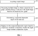
- FIG. 1 illustrates a flow chart of an information processing method provided by some embodiments of the disclosure. As shown in FIG. 1 , the information processing method includes the following steps: 101: acquiring a depth image.
- the depth image can be obtained or acquired by means of a depth sensor, which takes photographs of an object in a real-time manner.
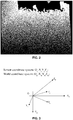
- FIG. 2 which illustrates a schematic diagram of a first scene using the information processing method provided by some embodiments of the disclosure.
- the depth image may also have already been taken and then be acquired.
- a user can upload a depth image to a processing device.
- a specified depth image can be acquired in a depth image library.
- a depth sensor i.e. a depth camera
- a depth sensor can generally include three types: a three-dimensional sensor based on structured lights, such as Kinect, RealSense, LeapMotion, Orbbec, etc., a three-dimensional sensor based on binocular stereo vision, such as ZED, Inuitive, Human + Director, etc., or a depth sensor based on the TOF principle, such as PMD, Panasonic, etc.
- the depth image can be acquired for subsequent detection to determine whether the current image contains a depression region.
- the depression region can exist on a road surface, and that in practical applications, it is not limited to the road surface, and can also be in other scenarios, such as in an indoor situation.
- FIG. 3 is a schematic diagram of a world coordinate system provided by some embodiments of this disclosure.
- an optical center of the depth sensor is used as an origin of the world coordinate system
- a horizontally rightward direction is chosen as a positive direction of an X axis
- a vertically downward direction is chosen as a positive direction of a Y axis
- a forward direction that is perpendicular to the plane is chosen as a positive direction of a Z axis, such that a world coordinate system is established.
- a point P( X c , Y c , Z c ) in the depth sensor coordinate system can be converted to a point P( X w , Y w , Z w ) in the world coordinate system.
- u , v are the coordinate values of the point P in the pixel coordinate system
- X c , Y c and Z c are the coordinate values of the point P in the camera coordinate system
- X w is the X-axis coordinate value of each pixel in the image in the world coordinate system
- Y w is the Y-axis coordinate value of each pixel in the image in the world coordinate system
- Z w is the Z-axis coordinate value of each pixel in the image in the world coordinate system
- ⁇ , ⁇ and ⁇ describe the attitude angle of the depth sensor, respectively representing a rotation angle of the X, Y and Z axes of the depth sensor around the X, Y and Z axes of the world coordinate system.
- X c is the X-axis coordinate value of each pixel in the depth sensor coordinate system of the image
- Y c is the Y-axis coordinate value of each pixel in the depth sensor coordinate system of the image
- Z c is the Z-axis coordinate value of each pixel in the depth sensor coordinate system of the image
- M 3x4 is the camera's internal reference matrix.
- an image comprising Z w is the depth image in the world coordinate system.
- the depth image in the world coordinate system is processed, and a mean value of each row is calculated to thereby obtain a means-by-row graph.
- the depth image in the world coordinate system can be preprocessed.
- the preprocessing may include smoothing, filtering, denoising, and so on.
- a mean value of pixels in each row of pixels in the depth image can be calculated, and then based on a number of each row and a mean value corresponding to the each row, a means-by-row graph I rowsMean can be established.
- the means-by-row graph is processed to determine a suspected road area.
- the road surface has certain characteristics, regarding the Z w of the world coordinate system, the bottom-to-top direction thereof usually represents a near-to-far road surface, which has the characteristics of being monotonously increasing.
- the row mean values that are not monotonously increasing in the bottom-to-top direction can be first removed, and the remaining row mean values can be next filtered by lone points, and the micro-fault zones can then be connected to thereby obtain a preprocessed result. After the preprocessed result is obtained, the suspected road area in the depth image can be filtered according to the preprocessed result.
- a row in which the median of a column vector for the row mean is 0 can be set as 0. Then each pixel position, if a difference between a depth value of the each pixel in the depth image and a corresponding value of the column vector for a row mean is greater than or equal to a preset level of tolerance for road undulation, is set as 0; and each pixel position in the depth image having values of not zero is determined as the suspected road area.
- the suspected road area is judged based on a preset position threshold of the main plane to thereby determine the road area in the depth image.
- a selection strategy can be set in advance. For example, an area with a largest area and with a distance from the lowest position of the suspected road area to the lowest position of the depth map Z w not exceeding ⁇ rows can be selected. Specifically, it can be set that: ⁇ rows ⁇ 5 ⁇ % ⁇ H Zw ;
- ⁇ rows represents a threshold value for the position of the main plane
- H Zw represents a height of the depth image Z w .
- the process of determining a suspected depression region in a road area can be as follows: Firstly, a mean value for each row in the road area is calculated. Because there are some error factors in the road area, the road area can be preprocessed in advance. In a specific implementation process, the preprocessing can include smoothing, filtering, denoising and other processing. Next, the mean value for each row of the preprocessed road area can be calculated.
- the specific calculation method can be referenced to the description as mentioned above.
- Z wGnd ( i, j ) is the depth value of the depth image corresponding to the road area at the coordinates ( i , j ), and I rowsMeanGnd ( i ) is the mean value of the depth image corresponding to the road area at the row i ; and ⁇ is the preset level of tolerance for depressions on the road surface.
- the setting of the value of ⁇ is related to the depth sensor used and to the actual road condition. If the value is set as too small, there will be relatively more false positives. If the value is set as too large, there will be relatively more false negatives, which is not beneficial to subsequent processing. Therefore, in combination with a large number of experimental data and empirical values, the range of ⁇ is usually between [5, 30].
- the row means can be filtered using a band-stop filter to obtain a suspected depression region as shown in FIG. 4 , which illustrates a diagram of a second scene using the information processing method provided by some embodiment of the disclosure.
- the row means After the row means have been filtered with the above formulas, the set of Z wGnd ( i, j ) thus obtained is the suspected depression region.
- the suspected depression region is preprocessed.
- the preprocessing treatments such as binarization and morphological processing, etc., can be performed over the suspected depression region to thereby remove the influence of burrs and islands on the subsequent extraction of depression edges.
- the contour of the suspected depression region C pothole is extracted, and the contour is used as a candidate depression region.
- the area of the candidate depression region is calculated.
- the area of the candidate depression region is set as S pothole .
- the Xw values: XwR, XwL, that correspond respectively to the right-most value and the left-most value of the candidate depression region, and the Zw values: ZwT, ZwB, that correspond respectively to the upper-most (i.e. top) value and the lower-most (i.e. bottom) value of the candidate depression region can be utilized, such that an area of a rectangular box comprising XwR, XwL, ZwT, and ZwB can be used for substitution.
- the area threshold is set as ⁇ , then if S pothole > ⁇ , the candidate depression region is determined to be a depression region, and the depth image acquired at the moment by the depth sensor contains a depression region.
- the setting of the value of ⁇ is related to the depth sensor that is used and the actual road condition. If the value is too small, there will be relatively more false positives. If the value is too large, there will be relatively more false negatives. Therefore, in combination with a large number of experimental data and empirical values, the value range can usually be between [100, 400].
- the information processing method provided in the embodiments of this disclosure processes the acquired depth image. Firstly, a road area in a depth image can be determined based on the row means of the depth image; then, a suspected depression region in the road area can be determined; finally, the suspected depression region can be judged based on a depression threshold to determine whether the depth image contains a depression region.
- the technical solutions provided by the embodiments of this application can effectively judge whether there is a depression region on a road surface. The detection efficiency is high and the calculation speed is fast. It can solve the problems of low accuracy in detecting depressions or objects below the horizontal line associated with the existing technologies.
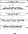
- FIG. 5 shows another flow chart of an information processing method provided by some embodiments of the disclosure.
- the embodiments of the information processing method can further include the following step: 105. Deleting the candidate depression region if the area of the candidate depression region is less than or equal to the area threshold.
- the area of the candidate depression region is set as S pothole , and the area threshold is set as ⁇ . Then if S pothole ⁇ ⁇ , the candidate depression region is determined as a non-depression region, and the candidate depression region can be deleted.
- FIG. 6 shows yet another flow chart of an information processing method provided by some embodiments of the disclosure. As shown in FIG. 6 , the information processing method further includes the following step: 106. Outputting a prompt message if it is determined that the depth image contains a depression region.
- a detection module of the product can feed or transmit parameters to a corresponding prompting module, so that the prompting module can output a prompt message.
- the prompt message can include voice information, vibration information, text information, sound information, optical light information, etc.
- FIG. 7 is a schematic diagram illustrating a structure of an information processing device according to some embodiment of the disclosure. As shown in FIG. 7 , the embodiments of the device include: an acquisition unit 11, a processing unit 12, a determination unit 13 and a judgment unit 14.
- the acquisition unit 11 is configured to acquire a depth image.
- the processing unit 12 is configured to process the depth image to obtain a means-by-row graph, and then to determine a road area in the depth image based on the means-by-row graph.
- the determination unit 13 is configured to determine a suspected depression region in the road area.
- the judgment unit 14 is configured to judge over the suspected depression region based on the depression threshold to thereby determine whether the depth image contains a depression region.
- the depth image can be an image under a camera/sensor coordinate system.
- the processing unit 12 can be specifically configured:
- the determination unit 13 is configured:
- the judgment unit 14 is specifically configured:
- the information processing device provided in the embodiments of this application can be used to implement the technical scheme of the information processing method as shown in FIG. 1 . Because the implementation principle and technical effects are similar, the description thereof is not repeated herein.
- FIG. 8 illustrates a schematic diagram of a structure of the information processing device according to some other embodiments of the disclosure. As shown in FIG. 8 , the embodiments of the information processing device further include a deletion unit 15.
- the deletion unit 15 is configured to delete the candidate depression region if the area of the candidate depression region is less than or equal to the area threshold.
- the information processing device provided in this embodiments of the application disclosed herein can be used to implement the technical scheme of the embodiment of the method shown in FIG. 5 . Because the implementation principle and technical effects are similar, the description thereof is not repeated herein.
- FIG. 9 shows a schematic diagram of a structure of the information processing device according to yet another embodiment of the present application. As shown in FIG. 9 , the embodiment of the device further includes an output unit 16.
- the output unit is configured to output a prompt message upon determining that the depth image contains a depression region.
- the information processing device provided in the embodiment of the present application can be used to implement the technical scheme of the embodiment of the method shown in FIG. 6 . Because the implementation principle and technical effects are similar, the description thereof is not repeated herein.
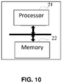
- FIG. 10 is a schematic diagram of the cloud-based processing device provided by some embodiments of this application.
- the cloud processing device includes a processor 21 and a memory 22.
- the memory 22 is configured to store instructions. When the instructions are executed by the processor 21, the device can execute any of the embodiments of the method as described above.
- the cloud processing device provided in the embodiments of the present application can be used to implement the technical schemes of the method embodiments shown in any of FIGS. 1-6 . Because the implementation principle and technical effects are similar, description thereof is not repeated herein.
- embodiments of the present application also provide a computer program product which can be directly loaded into an internal memory of a computer and contains software codes. After the computer program is loaded and executed, the computer program can realize any of the embodiments of the method as described above.
- the cloud processing device provided in the embodiment of the present application can be used to implement the technical scheme of the method embodiments shown in any of FIGS. 1-6 . Because its implementation principle and technical effects are similar, description thereof is not repeated herein.
- the system, device and method disclosed may be implemented in other ways.
- the embodiments of the device described above are merely illustrative.
- the division of the units described above is only a logical functional division, and in actual practice, there may be other ways of division. For instance, multiple units or components can be combined or integrated into a system; some features can be ignored or not implemented.
- the coupling, direct coupling, or communicative connection shown or discussed above may be through some interfaces, or an indirect coupling between devices or units, which may be in an electrical, a mechanical or other forms.
- separation components may or may not be physically separated, and the components displayed as a unit may or may not be a physical unit. That is, it may be located in one place or may be distributed over multiple network units. Some or all of the units can be selected according to actual needs to achieve the purpose of the present embodiments.
- the functional units in the various embodiments of the present application may be integrated in one processing unit, or may be physically present as separate units, or may be integrated in one unit by two or more units.
- the above integrated units can be implemented either in the form of hardware or in the form of hardware plus software functional units.
- the integrated unit realized in the form of software functional unit can be stored in a computer readable storage medium.
- the above software functional unit can be stored in a storage medium, including instructions for a computer device (i.e. a personal computer, a server, a network device, etc.) or a processor to perform some steps of the method described in the various embodiments of the present application.
- the aforementioned storage medium can include: a U disk, a mobile hard disk, a Read-Only Memory (ROM), a Random Access Memory (RAM), a disk or a CD, or another medium that can store program codes.
Landscapes
- Engineering & Computer Science (AREA)
- Physics & Mathematics (AREA)
- General Physics & Mathematics (AREA)
- Theoretical Computer Science (AREA)
- Multimedia (AREA)
- Computer Vision & Pattern Recognition (AREA)
- Quality & Reliability (AREA)
- Image Analysis (AREA)
- Image Processing (AREA)
- Traffic Control Systems (AREA)
Abstract
Description
- The present disclosure relates to the field of data processing technologies, and specifically to an information processing method and device, a cloud-based processing device, and a computer program product.
- With the rapid development of the Internet of Things (IoTs) technologies, pervasive computing, holographic computing, cloud computing and other new models of data computing have been gradually stepping into our daily lives, and have been applied to a variety of fields, among which computer vision is a representative field. Computer vision is a branch of science that studies how to make a machine "see". To be more specific, it is machine vision utilizing a device to substitute human eyes to recognize, track, and measure a target. Then image processing is further performed, using a processor to process the data thus obtained into images that are more suitable for human eyes to observe, or are transmitted to an instrument for detection.
- In practical applications, machine vision can be applied in many scenarios. For example, machine vision can be applied to a guiding stick, which is used to avoid obstacles in front of a visually impaired person. In another example, machine vision can be applied in the field of navigation, which is used to detect a road and obstacles on the surface of the road.
- Most of the existing technologies, however, rely on the information that is detected, such as color and shape, etc., and rely on the segmentation and contrast of strong edge information, so as to determine the shape of an object. Yet the detection of depressions or pits, or objects below the horizontal line typically has a relatively low accuracy.
- Embodiments of the present disclosure provide an information processing method, device, cloud-based processing device, and computer program product, which relate to the field of data processing technologies and can cause an increased efficiency in detecting whether a road area contains a depression region.
- In a first aspect, embodiments of the present application provide an information processing method, which includes:
- acquiring a depth image;
- processing the depth image to obtain a means-by-row graph, and determining a road area in the depth image based on the means-by-row graph;
- determining a suspected depression region in the road area; and
- judging over the suspected depression region based on a depression threshold to determine whether the depth image contains a depression region.
- In a second aspect, embodiments of the present application further provide an information processing device, which includes:
- an acquisition unit, configured to acquire a depth image;
- a processing unit, configured to process the depth image to obtain a means-by-row graph, and then to determine a road area in the depth image based on the means-by-row graph;
- a determination unit, configured to determine a suspected depression region in the road area; and
- a judgment unit, configured to judge over the suspected depression region based on the depression threshold to thereby determine whether the depth image contains a depression region.
- In a third aspect, embodiments of the present application further provide a cloud processing device, which includes a processor and a memory. The memory is configured to store instructions which, when executed by the processor, cause the device to execute the method according to any one of embodiments provided in the first aspect of the present disclosure.
- In a fourth aspect, embodiments of the present application further provide a computer program product capable of being directly loaded into an internal memory of a computer, which comprises software codes which, after being loaded and executed by the computer, cause the computer to realize the method according to any one of embodiments provided in the first aspect of the present disclosure.
- In the information processing method and device, the cloud-based processing device, and the computer program product disclosed in the various embodiments of the present application, a depth image is acquired and processed. Firstly, a road area in the depth image can be determined according to row means of the depth image; then a suspected depression region in the road area can be determined; and finally, the suspected depression region can be judged over based on a depression threshold to thereby determine whether the depth image contains a depression region. The technical solutions provided by the embodiments of this application can effectively judge whether there is a depression region on a road surface. The detection efficiency is high and the calculation speed is fast. It can solve the problems of low accuracy in detecting depressions or objects below the horizontal line associated with the existing technologies.
- In order to more clearly describe the technical solutions or schemes that are disclosed in embodiments of this present application or in existing technologies, some drawings that accompany some embodiments of this present application or some existing technologies are briefly described herein. It is obvious that these accompanying drawings as described in the following represent some illustrating examples of the embodiments of the present application. People of ordinary skills in the field can, in the premise of not paying creative labor, also obtain other drawings based on these drawings.
-
FIG. 1 is a flow chart of an information processing method provided by some embodiments of the disclosure; -
FIG. 2 is a diagram of a first scene using the information processing method provided by some embodiment of the disclosure; -
FIG. 3 is a schematic diagram of a world coordinate system provided by some embodiments of this disclosure; -
FIG. 4 is a diagram of a second scene using the information processing method provided by some embodiment of the disclosure; -
FIG. 5 illustrates a flow chart of an information processing method provided by another embodiment of the disclosure; -
FIG. 6 illustrates a flow chart of an information processing method provided by yet another embodiment of the disclosure; -
FIG. 7 is a schematic diagram illustrating a structure of an information processing device according to some embodiment of the disclosure; -
FIG. 8 is a schematic diagram illustrating a structure of an information processing device according to another embodiment of the disclosure; -
FIG. 9 is a schematic diagram illustrating a structure of an information processing device according to yet another embodiment of the disclosure; -
FIG. 10 is a schematic diagram of the cloud-based processing device provided by some embodiments of this application. - In order to make the goal, the technical solution, and the advantages provided in the embodiments of the present disclosure clearer, in the following a detailed and complete description is further provided for some illustrating embodiments which are accompanied with drawings. It is obvious that the embodiments described herein represent only part of, and do not exhaustively cover all of, the embodiments of this disclosure. Based on these embodiments disclosed in the present application, all other embodiments, as long as they can be acquired by a person of ordinary skill in the field without making creative work, shall fall within the scope of the protection of the present application.
- The terminologies used in the embodiments of this present disclosure are for the purpose of describing the particular embodiment only, and are not intended to impose any limitation thereto. Any singular forms, such as "a", "an", "one", "the", and "said", if used in the embodiments of the disclosure and in the claims that are appended therewith, are also intended to include their plural forms, unless the context clearly indicates otherwise.
- It should be understood that the term "and/or" in this disclosure is used only to describe the relationship between associated objects, and indicates that there can be three kinds of relationships. In one example of A and/or B, it can be expressed as: A alone, A and B together, and B alone. In addition, the character "/" throughout this disclosure generally indicates that the relationship between one object that precedes and another object that follows is an "or" relationship.
- Depending on the context, the phrase "if..." as used in the disclosure can be interpreted as "in situation where...", "when...", or "in response to the determination that...", or "upon detecting...". Similarly, depending on the context, the phrase "if determining..." or "if detecting... (condition or event under statement)" can be interpreted as "when determining..." or "in response to the determination that..." or "when detecting... (condition or event under statement)" or "in response to detection that... (condition or event of statement)".
- In existing technologies, machine vision can be applied in many scenarios. For example, machine vision can be applied to a guiding stick, or can be applied to the field of navigation, whereas in detecting a road surface, it is most commonly used for the road surface detection or obstacle detection. Moreover, in the detection process using a seed point region growing method, a random point least-square method, a mean block height method, a V-disparity algorithm, etc., there are issues or problems such as complex calculations, and vulnerability to impacts from samples and actual environments such that the accuracy of results is influenced, the recognition efficiency is low, and the detection range is limited. As such, embodiments of the present disclosure provide an information processing method, which utilizes the depth images that are obtained or acquired to detect whether there are depressions on the road surface. This method has a high detection efficiency, and can thus be applied to many scenarios such as assisting a visually impaired person to move, obstacle avoidance by robots, unmanned driving, and navigation, etc. Specifically,
FIG. 1 illustrates a flow chart of an information processing method provided by some embodiments of the disclosure. As shown inFIG. 1 , the information processing method includes the following steps:
101: acquiring a depth image. - In some embodiments of this application, the depth image can be obtained or acquired by means of a depth sensor, which takes photographs of an object in a real-time manner. as shown in
FIG. 2 , which illustrates a schematic diagram of a first scene using the information processing method provided by some embodiments of the disclosure. The depth image may also have already been taken and then be acquired. In one example, a user can upload a depth image to a processing device. In another example, a specified depth image can be acquired in a depth image library. - Specifically, according to some embodiments of the disclosure, a depth sensor (i.e. a depth camera) can generally include three types: a three-dimensional sensor based on structured lights, such as Kinect, RealSense, LeapMotion, Orbbec, etc., a three-dimensional sensor based on binocular stereo vision, such as ZED, Inuitive, Human + Director, etc., or a depth sensor based on the TOF principle, such as PMD, Panasonic, etc.
- Through the above approaches, the depth image can be acquired for subsequent detection to determine whether the current image contains a depression region. It is understandable that in these embodiments of the present application, the depression region can exist on a road surface, and that in practical applications, it is not limited to the road surface, and can also be in other scenarios, such as in an indoor situation.
- 102. Processing the depth image to obtain a means-by-row graph, and determining a road area in the depth image based on the means-by-row graph.
- In the embodiments of this application disclosed herein, when a depth sensor is used to capture the depth image in the real-time manner, a camera/sensor coordinate system can be first converted to a world coordinate system through coordinate transformation of the depth image.
FIG. 3 is a schematic diagram of a world coordinate system provided by some embodiments of this disclosure. As specifically shown inFIG. 3 , an optical center of the depth sensor is used as an origin of the world coordinate system, a horizontally rightward direction is chosen as a positive direction of an X axis, a vertically downward direction is chosen as a positive direction of a Y axis, and a forward direction that is perpendicular to the plane is chosen as a positive direction of a Z axis, such that a world coordinate system is established. Because the origin of the world coordinate system coincides with the origin of the depth sensor coordinate system, there is only a rotation relationship between the two coordinate systems, there is also no translation relationship, and there is furthermore no relationship among the pixel coordinate system, the camera coordinate system and the world coordinate system. As such, based on an attitude angle of the depth sensor, a point P(Xc, Yc, Zc ) in the depth sensor coordinate system can be converted to a point P(Xw, Yw, Zw ) in the world coordinate system. The calculation formulas are as follows:
- Herein, u, v are the coordinate values of the point P in the pixel coordinate system, Xc , Yc and Zc are the coordinate values of the point P in the camera coordinate system, Xw is the X-axis coordinate value of each pixel in the image in the world coordinate system, Yw is the Y-axis coordinate value of each pixel in the image in the world coordinate system, and Zw is the Z-axis coordinate value of each pixel in the image in the world coordinate system; α, β and γ describe the attitude angle of the depth sensor, respectively representing a rotation angle of the X, Y and Z axes of the depth sensor around the X, Y and Z axes of the world coordinate system. Xc is the X-axis coordinate value of each pixel in the depth sensor coordinate system of the image; Yc is the Y-axis coordinate value of each pixel in the depth sensor coordinate system of the image; and Zc is the Z-axis coordinate value of each pixel in the depth sensor coordinate system of the image; M3x4 is the camera's internal reference matrix.
- In the embodiments of this present application, an image comprising Zw is the depth image in the world coordinate system.
- Then the depth image in the world coordinate system is processed, and a mean value of each row is calculated to thereby obtain a means-by-row graph. In the embodiments of this application, in order to improve the computational efficiency, the depth image in the world coordinate system can be preprocessed. In one specific implementation process, the preprocessing may include smoothing, filtering, denoising, and so on. Then based on the characteristics that a same row in the depth image of a ground/road surface has a similar depth value, a mean value of pixels in each row of pixels in the depth image can be calculated, and then based on a number of each row and a mean value corresponding to the each row, a means-by-row graph IrowsMean can be established.
- Then, the means-by-row graph is processed to determine a suspected road area. Specifically, because the road surface has certain characteristics, regarding the Zw of the world coordinate system, the bottom-to-top direction thereof usually represents a near-to-far road surface, which has the characteristics of being monotonously increasing. As such, in the means-by-row graph IrowsMean , the row mean values that are not monotonously increasing in the bottom-to-top direction can be first removed, and the remaining row mean values can be next filtered by lone points, and the micro-fault zones can then be connected to thereby obtain a preprocessed result. After the preprocessed result is obtained, the suspected road area in the depth image can be filtered according to the preprocessed result. Specifically, in the depth image that has been preprocessed, a row in which the median of a column vector for the row mean is 0 can be set as 0. Then each pixel position, if a difference between a depth value of the each pixel in the depth image and a corresponding value of the column vector for a row mean is greater than or equal to a preset level of tolerance for road undulation, is set as 0; and each pixel position in the depth image having values of not zero is determined as the suspected road area.
- Finally, the suspected road area is judged based on a preset position threshold of the main plane to thereby determine the road area in the depth image. Specifically, a selection strategy can be set in advance. For example, an area with a largest area and with a distance from the lowest position of the suspected road area to the lowest position of the depth map Zw not exceeding εrows can be selected. Specifically, it can be set that:

- Herein, εrows represents a threshold value for the position of the main plane, HZw represents a height of the depth image Zw .
- 103. Determining a suspected depression region in the road area.
- According to some embodiments of the present application, the process of determining a suspected depression region in a road area can be as follows:
Firstly, a mean value for each row in the road area is calculated. Because there are some error factors in the road area, the road area can be preprocessed in advance. In a specific implementation process, the preprocessing can include smoothing, filtering, denoising and other processing. Next, the mean value for each row of the preprocessed road area can be calculated. The specific calculation method can be referenced to the description as mentioned above. - Then, a band-stop filter is established. According to some embodiments of this application, the formula of the band-stop filter is as follows:

- Herein, ZwGnd (i, j) is the depth value of the depth image corresponding to the road area at the coordinates (i, j), and IrowsMeanGnd (i) is the mean value of the depth image corresponding to the road area at the row i; and δ is the preset level of tolerance for depressions on the road surface.
- It is noted that in practical implementation, the setting of the value of δ is related to the depth sensor used and to the actual road condition. If the value is set as too small, there will be relatively more false positives. If the value is set as too large, there will be relatively more false negatives, which is not beneficial to subsequent processing. Therefore, in combination with a large number of experimental data and empirical values, the range of δ is usually between [5, 30].
- Finally, the row means can be filtered using a band-stop filter to obtain a suspected depression region as shown in
FIG. 4 , which illustrates a diagram of a second scene using the information processing method provided by some embodiment of the disclosure. After the row means have been filtered with the above formulas, the set of ZwGnd (i, j) thus obtained is the suspected depression region. - 104. Judging over the suspected depression region based on a depression threshold to determine whether the depth image contains a depression region.
- In the embodiments of the application disclosed herein, firstly, the suspected depression region is preprocessed. Specifically, the preprocessing treatments, such as binarization and morphological processing, etc., can be performed over the suspected depression region to thereby remove the influence of burrs and islands on the subsequent extraction of depression edges.
- Then, the contour of the suspected depression region Cpothole is extracted, and the contour is used as a candidate depression region.
- Next, the area of the candidate depression region is calculated. In the embodiments disclosed herein, the area of the candidate depression region is set as Spothole . In practical application, besides the conventional calculation method, the Xw values: XwR, XwL, that correspond respectively to the right-most value and the left-most value of the candidate depression region, and the Zw values: ZwT, ZwB, that correspond respectively to the upper-most (i.e. top) value and the lower-most (i.e. bottom) value of the candidate depression region, can be utilized, such that an area of a rectangular box comprising XwR, XwL, ZwT, and ZwB can be used for substitution.
- Finally, when the area of the candidate depression region is larger than an area threshold, it is determined that the depth image contains a depression region. In the embodiments of this application disclosed herein, the area threshold is set as ε, then if Spothole > ε, the candidate depression region is determined to be a depression region, and the depth image acquired at the moment by the depth sensor contains a depression region.
- It is noted that in practical application, the setting of the value of ε is related to the depth sensor that is used and the actual road condition. If the value is too small, there will be relatively more false positives. If the value is too large, there will be relatively more false negatives. Therefore, in combination with a large number of experimental data and empirical values, the value range can usually be between [100, 400].
- The information processing method provided in the embodiments of this disclosure processes the acquired depth image. Firstly, a road area in a depth image can be determined based on the row means of the depth image; then, a suspected depression region in the road area can be determined; finally, the suspected depression region can be judged based on a depression threshold to determine whether the depth image contains a depression region. The technical solutions provided by the embodiments of this application can effectively judge whether there is a depression region on a road surface. The detection efficiency is high and the calculation speed is fast. It can solve the problems of low accuracy in detecting depressions or objects below the horizontal line associated with the existing technologies.
- On the basis of the disclosure as set forth above, in order to reduce the pressure on the buffer and improve the calculation speed, when judging over the suspected depression region based on the depression threshold, the following operations can be performed over the depth image determined to be absent of a depression region. Specifically,
FIG. 5 shows another flow chart of an information processing method provided by some embodiments of the disclosure. As shown inFIG. 5 , the embodiments of the information processing method can further include the following step:
105. Deleting the candidate depression region if the area of the candidate depression region is less than or equal to the area threshold. - In the embodiments disclosed herein, the area of the candidate depression region is set as Spothole , and the area threshold is set as ε. Then if Spothole ≤ ε, the candidate depression region is determined as a non-depression region, and the candidate depression region can be deleted.
- In the above description, the process of determining a depression region is provided. When the scheme provided in the embodiments of this application is applied in an actual product, it can be further configured to provide a prompting effect to a user. Specifically,
FIG. 6 shows yet another flow chart of an information processing method provided by some embodiments of the disclosure. As shown inFIG. 6 , the information processing method further includes the following step:
106. Outputting a prompt message if it is determined that the depth image contains a depression region. - In the embodiments of this application disclosed herein, if it is determined that the acquired depth image contains a depression region, a detection module of the product can feed or transmit parameters to a corresponding prompting module, so that the prompting module can output a prompt message. In a specific implementation, the prompt message can include voice information, vibration information, text information, sound information, optical light information, etc.
- In order to realize the information processing method as described above, embodiments of this application further provide an information processing device.
FIG. 7 is a schematic diagram illustrating a structure of an information processing device according to some embodiment of the disclosure. As shown inFIG. 7 , the embodiments of the device include: anacquisition unit 11, aprocessing unit 12, adetermination unit 13 and ajudgment unit 14. - The
acquisition unit 11 is configured to acquire a depth image. - The
processing unit 12 is configured to process the depth image to obtain a means-by-row graph, and then to determine a road area in the depth image based on the means-by-row graph. - The
determination unit 13 is configured to determine a suspected depression region in the road area. - The
judgment unit 14 is configured to judge over the suspected depression region based on the depression threshold to thereby determine whether the depth image contains a depression region. - In a specific implementation process, the depth image can be an image under a camera/sensor coordinate system.
- The
processing unit 12 can be specifically configured: - to perform a coordinate transformation over the depth image to thereby convert the camera coordinate system into a world coordinate system;
- to process the depth image in the world coordinate system, and calculate row means therein to thereby obtain a means-by-row graph;
- to process the means-by-row graph to determine a suspected road area; and
- to judge over the suspected road area based on a preset position threshold of a main plane to determine the road area in the depth image.
- In a specific implementation process, the
determination unit 13 is configured: - to calculate row means in the road area;
- to establish a band-stop filter; and
- to filter the row means by means of the band-stop filter to thereby obtain the suspected depression region.
- In a specific implementation process, the
judgment unit 14 is specifically configured: - to preprocess the suspected depression region;
- to extract a contour of the suspected depression region and regard the contour as a candidate depression region;
- to calculate an area of the candidate depression region; and
- to determine, if the area of the candidate depression region is larger than an area threshold, that the depth image contains a depression region.
- The information processing device provided in the embodiments of this application can be used to implement the technical scheme of the information processing method as shown in
FIG. 1 . Because the implementation principle and technical effects are similar, the description thereof is not repeated herein. - On the basis of the foregoing contents, embodiments of the present application further provide an information processing device.
FIG. 8 illustrates a schematic diagram of a structure of the information processing device according to some other embodiments of the disclosure. As shown inFIG. 8 , the embodiments of the information processing device further include adeletion unit 15. - The
deletion unit 15 is configured to delete the candidate depression region if the area of the candidate depression region is less than or equal to the area threshold. - The information processing device provided in this embodiments of the application disclosed herein can be used to implement the technical scheme of the embodiment of the method shown in
FIG. 5 . Because the implementation principle and technical effects are similar, the description thereof is not repeated herein. - On the basis of the contents that forego, embodiments of the present application further provide an information processing device.
FIG. 9 shows a schematic diagram of a structure of the information processing device according to yet another embodiment of the present application. As shown inFIG. 9 , the embodiment of the device further includes anoutput unit 16. - The output unit is configured to output a prompt message upon determining that the depth image contains a depression region.
- The information processing device provided in the embodiment of the present application can be used to implement the technical scheme of the embodiment of the method shown in
FIG. 6 . Because the implementation principle and technical effects are similar, the description thereof is not repeated herein. - In order to realize the method described above, embodiments of this application further provide a cloud processing device.
FIG. 10 is a schematic diagram of the cloud-based processing device provided by some embodiments of this application. As shown inFIG. 10 , the cloud processing device includes aprocessor 21 and amemory 22. Thememory 22 is configured to store instructions. When the instructions are executed by theprocessor 21, the device can execute any of the embodiments of the method as described above. - The cloud processing device provided in the embodiments of the present application can be used to implement the technical schemes of the method embodiments shown in any of
FIGS. 1-6 . Because the implementation principle and technical effects are similar, description thereof is not repeated herein. - In order to realize the method described above, embodiments of the present application also provide a computer program product which can be directly loaded into an internal memory of a computer and contains software codes. After the computer program is loaded and executed, the computer program can realize any of the embodiments of the method as described above.
- The cloud processing device provided in the embodiment of the present application can be used to implement the technical scheme of the method embodiments shown in any of
FIGS. 1-6 . Because its implementation principle and technical effects are similar, description thereof is not repeated herein. - Persons of ordinary skills in the field can clearly understand that, for the convenience and simplicity of the description, the specific working processes of the system, device and units described above may refer to the corresponding processes in the embodiments of the method described above, and is not repeated herein.
- In the several embodiments provided in this application, it should be understood that the system, device and method disclosed may be implemented in other ways. For example, the embodiments of the device described above are merely illustrative. In one example, the division of the units described above is only a logical functional division, and in actual practice, there may be other ways of division. For instance, multiple units or components can be combined or integrated into a system; some features can be ignored or not implemented. On the other hand, the coupling, direct coupling, or communicative connection shown or discussed above may be through some interfaces, or an indirect coupling between devices or units, which may be in an electrical, a mechanical or other forms.
- The "units" described above as separation components may or may not be physically separated, and the components displayed as a unit may or may not be a physical unit. That is, it may be located in one place or may be distributed over multiple network units. Some or all of the units can be selected according to actual needs to achieve the purpose of the present embodiments.
- In addition, the functional units in the various embodiments of the present application may be integrated in one processing unit, or may be physically present as separate units, or may be integrated in one unit by two or more units. The above integrated units can be implemented either in the form of hardware or in the form of hardware plus software functional units.
- The integrated unit realized in the form of software functional unit can be stored in a computer readable storage medium. The above software functional unit can be stored in a storage medium, including instructions for a computer device (i.e. a personal computer, a server, a network device, etc.) or a processor to perform some steps of the method described in the various embodiments of the present application. The aforementioned storage medium can include: a U disk, a mobile hard disk, a Read-Only Memory (ROM), a Random Access Memory (RAM), a disk or a CD, or another medium that can store program codes.
- The above description represents only relatively better embodiments of this application, which are not intended to impose any limitations on this present disclosure. Any modifications, equivalent substitutions, improvements, etc., if made within the spirit and principles of this application, shall be included in the scope of protection of this application.
Claims (14)
- An information processing method, comprising:acquiring a depth image;processing the depth image to obtain a means-by-row graph, and determining a road area in the depth image based on the means-by-row graph;determining a suspected depression region in the road area; andjudging over the suspected depression region based on a depression threshold to determine whether the depth image contains a depression region.
- The method of claim 1, wherein the depth image is an image under a camera coordinate system, wherein the processing the depth image to obtain a means-by-row graph, and determining a road area in the depth image based on the means-by-row graph comprises:performing a coordinate transformation over the depth image to thereby convert the camera coordinate system into a world coordinate system;processing the depth image in the world coordinate system, and calculating row means in the depth image to thereby obtain a means-by-row graph;processing the means-by-row graph to determine a suspected road area; andjudging over the suspected road area based on a preset main plane position threshold to determine the road area in the depth image.
- The method of claim 1, wherein the determining a suspected depression region in the road area comprises:calculating row means in the road area;establishing a band-stop filter; andfiltering the row means by means of the band-stop filter to thereby obtain the suspected depression region.
- The method of claim 1, wherein the judging over the suspected depression region based on a depression threshold to determine whether the depth image contains a depression region comprises:preprocessing the suspected depression region;extracting a contour of the suspected depression region and regarding the contour as a candidate depression region;calculating an area of the candidate depression region; anddetermining, if an area of the candidate depression region is larger than an area threshold, that the depth image contains a depression region.
- The method of claim 4, further comprising:
deleting, if the area of the candidate depression region is less than or equal to the area threshold, the candidate depression region. - The method of claim 1 or claim 4, further comprising:
outputting a prompt message upon determining that the depth image contains a depression region. - An information processing device, comprising:an acquisition unit, configured to acquire a depth image;a processing unit, configured to process the depth image to obtain a means-by-row graph, and then to determine a road area in the depth image based on the means-by-row graph;a determination unit, configured to determine a suspected depression region in the road area; anda judgment unit, configured to judge over the suspected depression region based on the depression threshold to thereby determine whether the depth image contains a depression region.
- The device of claim 7, wherein the depth image is an image under a camera coordinate system, wherein the processing unit is configured to:perform a coordinate transformation over the depth image to thereby convert the camera coordinate system into a world coordinate system;process the depth image in the world coordinate system, and calculate row means therein to thereby obtain a means-by-row graph;process the means-by-row graph to determine a suspected road area; andjudge over the suspected road area based on a preset position threshold of a main plane to determine the road area in the depth image.
- The device of claim 7, wherein the determination unit is configured to:calculate row means in the road area;establish a band-stop filter; andfilter the row means by means of the band-stop filter to thereby obtain the suspected depression region.
- The device of claim 7, wherein the judgment unit is configured to:preprocess the suspected depression region;extract a contour of the suspected depression region and regard the contour as a candidate depression region;calculate an area of the candidate depression region; anddetermine, if an area of the candidate depression region is larger than an area threshold, that the depth image comprises a depression region.
- The device of claim 10, further comprising a deletion unit, configured to delete, if the area of the candidate depression region is less than or equal to the area threshold, the candidate depression region.
- The device of claim 7 or claim 10, further comprising an output unit, configured to output a prompt message upon determining that the depth image comprises a depression region.
- A cloud processing device, comprising a processor and a memory, wherein:
the memory is configured to store instructions which, when executed by the processor, cause the device to execute the method according to any one of claims 1-6. - A computer program product capable of being directly loaded into an internal memory of a computer, comprising software codes which, after being loaded and executed by the computer, cause the computer to realize the method according to any one of claims 1-6.
Applications Claiming Priority (1)
| Application Number | Priority Date | Filing Date | Title |
|---|---|---|---|
| PCT/CN2018/072132 WO2019136641A1 (en) | 2018-01-10 | 2018-01-10 | Information processing method and apparatus, cloud processing device and computer program product |
Publications (2)
| Publication Number | Publication Date |
|---|---|
| EP3605460A1 true EP3605460A1 (en) | 2020-02-05 |
| EP3605460A4 EP3605460A4 (en) | 2020-06-17 |
Family
ID=62657689
Family Applications (1)
| Application Number | Title | Priority Date | Filing Date |
|---|---|---|---|
| EP18899638.3A Withdrawn EP3605460A4 (en) | 2018-01-10 | 2018-01-10 | INFORMATION PROCESSING METHOD AND APPARATUS, CLOUD PROCESSING DEVICE AND COMPUTER PROGRAM PRODUCT |
Country Status (5)
| Country | Link |
|---|---|
| US (1) | US11379963B2 (en) |
| EP (1) | EP3605460A4 (en) |
| JP (1) | JP6955783B2 (en) |
| CN (1) | CN108235774B (en) |
| WO (1) | WO2019136641A1 (en) |
Families Citing this family (15)
| Publication number | Priority date | Publication date | Assignee | Title |
|---|---|---|---|---|
| CN109074490B (en) * | 2018-07-06 | 2023-01-31 | 达闼机器人股份有限公司 | Path detection method, related device and computer readable storage medium |
| CN108885791B (en) * | 2018-07-06 | 2022-04-08 | 达闼机器人有限公司 | Ground detection method, related device and computer readable storage medium |
| CN110852312B (en) * | 2020-01-14 | 2020-07-17 | 深圳飞科机器人有限公司 | Cliff detection method, control method of mobile robot, and mobile robot |
| CN111274939B (en) * | 2020-01-19 | 2023-07-14 | 交信北斗科技有限公司 | Automatic extraction method of road surface potholes and damage based on monocular camera |
| CN113536854B (en) * | 2020-04-20 | 2025-01-28 | 蘑菇车联信息科技有限公司 | A method, device and server for generating high-precision map road signs |
| CN112070700B (en) * | 2020-09-07 | 2024-03-29 | 深圳市凌云视迅科技有限责任公司 | Method and device for removing protrusion interference noise in depth image |
| CN112099504B (en) * | 2020-09-16 | 2024-06-18 | 深圳优地科技有限公司 | Robot moving method, device, equipment and storage medium |
| CN112149656B (en) * | 2020-09-29 | 2025-07-04 | 腾讯科技(深圳)有限公司 | Method, device, computer equipment and storage medium for determining box ventilation cover area |
| CN112435297B (en) * | 2020-12-02 | 2023-04-18 | 达闼机器人股份有限公司 | Target object pose determining method and device, storage medium and electronic equipment |
| DE102021107904A1 (en) * | 2021-03-29 | 2022-09-29 | Conti Temic Microelectronic Gmbh | Method and system for determining ground level with an artificial neural network |
| CN115393813B (en) * | 2022-08-18 | 2023-05-02 | 中国人民公安大学 | Road identification method, device, equipment and storage medium based on remote sensing image |
| CN115760805B (en) * | 2022-11-24 | 2024-02-09 | 中山大学 | Positioning method for processing element surface depression based on visual touch sense |
| CN116258710B (en) * | 2023-03-16 | 2025-10-24 | 潍柴动力股份有限公司 | Method, device, equipment and medium for determining forage depth based on silage machine |
| CN116704459A (en) * | 2023-04-17 | 2023-09-05 | 蔚来汽车科技(安徽)有限公司 | Road Pothole Detection Method, System, Electronic Device, and Computer-Readable Storage Medium |
| CN116820125B (en) * | 2023-06-07 | 2023-12-22 | 哈尔滨市大地勘察测绘有限公司 | Unmanned seeder control method and system based on image processing |
Family Cites Families (12)
| Publication number | Priority date | Publication date | Assignee | Title |
|---|---|---|---|---|
| US9264673B2 (en) * | 2011-11-20 | 2016-02-16 | Magna Electronics, Inc. | Vehicle vision system with enhanced functionality |
| JP2014106897A (en) * | 2012-11-29 | 2014-06-09 | Toyota Motor Corp | Passage propriety determination device |
| CN104200453B (en) | 2014-09-15 | 2017-01-25 | 西安电子科技大学 | Parallax image correcting method based on image segmentation and credibility |
| CN104463145B (en) | 2014-12-23 | 2018-07-31 | 上海斐讯数据通信技术有限公司 | A kind of electronic equipment and obstacle based reminding method |
| CN104899869B (en) | 2015-05-14 | 2017-09-01 | 浙江大学 | Plane and disorder detection method based on RGB D cameras and attitude transducer |
| JP6811534B2 (en) | 2016-02-04 | 2021-01-13 | 株式会社トプコン | Road property display method and road property display device |
| CN106597690B (en) | 2016-11-23 | 2019-02-12 | 杭州视氪科技有限公司 | A path-predictive glasses for the visually impaired based on RGB-D camera and stereo |
| CN107341789B (en) | 2016-11-23 | 2019-12-17 | 杭州视氪科技有限公司 | A path prediction system and method for visually impaired persons based on RGB-D camera and stereo |
| US10140719B2 (en) * | 2016-12-22 | 2018-11-27 | TCL Research America Inc. | System and method for enhancing target tracking via detector and tracker fusion for unmanned aerial vehicles |
| CN206460410U (en) | 2017-02-04 | 2017-09-01 | 上海肇观电子科技有限公司 | Smart machine with augmented reality |
| CN106843491A (en) * | 2017-02-04 | 2017-06-13 | 上海肇观电子科技有限公司 | Smart machine and electronic equipment with augmented reality |
| US10788829B2 (en) * | 2017-12-20 | 2020-09-29 | International Business Machines Corporation | Self-driving vehicle passenger management |
-
2018
- 2018-01-10 EP EP18899638.3A patent/EP3605460A4/en not_active Withdrawn
- 2018-01-10 CN CN201880000099.1A patent/CN108235774B/en active Active
- 2018-01-10 JP JP2019559815A patent/JP6955783B2/en active Active
- 2018-01-10 WO PCT/CN2018/072132 patent/WO2019136641A1/en not_active Ceased
- 2018-01-10 US US16/609,447 patent/US11379963B2/en active Active
Also Published As
| Publication number | Publication date |
|---|---|
| JP6955783B2 (en) | 2021-10-27 |
| WO2019136641A1 (en) | 2019-07-18 |
| EP3605460A4 (en) | 2020-06-17 |
| US11379963B2 (en) | 2022-07-05 |
| JP2020518918A (en) | 2020-06-25 |
| CN108235774A (en) | 2018-06-29 |
| US20200090323A1 (en) | 2020-03-19 |
| CN108235774B (en) | 2020-07-14 |
Similar Documents
| Publication | Publication Date | Title |
|---|---|---|
| US11379963B2 (en) | Information processing method and device, cloud-based processing device, and computer program product | |
| CN109271944B (en) | Obstacle detection method, obstacle detection device, electronic apparatus, vehicle, and storage medium | |
| CN112967283B (en) | Target identification method, system, equipment and storage medium based on binocular camera | |
| CN115273062B (en) | 3D target detection method integrating three-dimensional laser radar and monocular camera | |
| CN115496923B (en) | Multi-mode fusion target detection method and device based on uncertainty perception | |
| CN114332394B (en) | A dynamic scene 3D reconstruction method based on semantic information | |
| CN108280401B (en) | Pavement detection method and device, cloud server and computer program product | |
| CN104902261B (en) | Apparatus and method for the road surface identification in low definition video flowing | |
| WO2021017211A1 (en) | Vehicle positioning method and device employing visual sensing, and vehicle-mounted terminal | |
| CN112097732A (en) | Binocular camera-based three-dimensional distance measurement method, system, equipment and readable storage medium | |
| CN114463832B (en) | Point cloud-based traffic scene line of sight tracking method and system | |
| CN112364693B (en) | Binocular vision-based obstacle recognition method, device, equipment and storage medium | |
| CN113901903A (en) | Road identification method and device | |
| CN116052120A (en) | Excavator night object detection method based on image enhancement and multi-sensor fusion | |
| CN111667523A (en) | Multi-mode multi-source based deep data refining method and system | |
| CN119888738A (en) | Multi-view semantic recognition method based on depth map assistance | |
| CN114692720A (en) | Image classification method, device, equipment and storage medium based on aerial view | |
| CN104915642B (en) | Front vehicles distance measuring method and device | |
| CN114972177A (en) | Road disease identification management method, device and intelligent terminal | |
| CN112509126A (en) | Method, device, equipment and storage medium for detecting three-dimensional object | |
| CN114359865A (en) | An obstacle detection method and related device | |
| CN114648686A (en) | A method, system and device for backlit water surface target recognition based on fusion of laser point cloud and RGB image data | |
| CN110197104B (en) | Distance measurement method and device based on vehicle | |
| EP4246455B1 (en) | Method and device for detecting object and vehicle | |
| CN117095382A (en) | Obstacle detection method, device, equipment and medium based on camera and radar |
Legal Events
| Date | Code | Title | Description |
|---|---|---|---|
| STAA | Information on the status of an ep patent application or granted ep patent |
Free format text: STATUS: THE INTERNATIONAL PUBLICATION HAS BEEN MADE |
|
| PUAI | Public reference made under article 153(3) epc to a published international application that has entered the european phase |
Free format text: ORIGINAL CODE: 0009012 |
|
| STAA | Information on the status of an ep patent application or granted ep patent |
Free format text: STATUS: REQUEST FOR EXAMINATION WAS MADE |
|
| 17P | Request for examination filed |
Effective date: 20191029 |
|
| AK | Designated contracting states |
Kind code of ref document: A1 Designated state(s): AL AT BE BG CH CY CZ DE DK EE ES FI FR GB GR HR HU IE IS IT LI LT LU LV MC MK MT NL NO PL PT RO RS SE SI SK SM TR |
|
| AX | Request for extension of the european patent |
Extension state: BA ME |
|
| A4 | Supplementary search report drawn up and despatched |
Effective date: 20200520 |
|
| RIC1 | Information provided on ipc code assigned before grant |
Ipc: G06T 7/00 20170101AFI20200514BHEP Ipc: G06K 9/32 20060101ALI20200514BHEP Ipc: G06T 5/20 20060101ALI20200514BHEP Ipc: G06K 9/46 20060101ALI20200514BHEP Ipc: G06K 9/00 20060101ALI20200514BHEP |
|
| STAA | Information on the status of an ep patent application or granted ep patent |
Free format text: STATUS: EXAMINATION IS IN PROGRESS |
|
| 17Q | First examination report despatched |
Effective date: 20201208 |
|
| DAV | Request for validation of the european patent (deleted) | ||
| DAX | Request for extension of the european patent (deleted) | ||
| RAP1 | Party data changed (applicant data changed or rights of an application transferred) |
Owner name: DATHA ROBOT CO., LTD. |
|
| RAP3 | Party data changed (applicant data changed or rights of an application transferred) |
Owner name: CLOUDMINDS ROBOTICS CO., LTD. |
|
| STAA | Information on the status of an ep patent application or granted ep patent |
Free format text: STATUS: THE APPLICATION IS DEEMED TO BE WITHDRAWN |
|
| 18D | Application deemed to be withdrawn |
Effective date: 20220802 |