EP3605396A1 - Card processing device and automated transaction device - Google Patents
Card processing device and automated transaction device Download PDFInfo
- Publication number
- EP3605396A1 EP3605396A1 EP17903546.4A EP17903546A EP3605396A1 EP 3605396 A1 EP3605396 A1 EP 3605396A1 EP 17903546 A EP17903546 A EP 17903546A EP 3605396 A1 EP3605396 A1 EP 3605396A1
- Authority
- EP
- European Patent Office
- Prior art keywords
- card
- magnetic
- conveyance
- processing device
- conveyed
- Prior art date
- Legal status (The legal status is an assumption and is not a legal conclusion. Google has not performed a legal analysis and makes no representation as to the accuracy of the status listed.)
- Granted
Links
Images


Classifications
-
- G—PHYSICS
- G06—COMPUTING OR CALCULATING; COUNTING
- G06K—GRAPHICAL DATA READING; PRESENTATION OF DATA; RECORD CARRIERS; HANDLING RECORD CARRIERS
- G06K7/00—Methods or arrangements for sensing record carriers, e.g. for reading patterns
- G06K7/10—Methods or arrangements for sensing record carriers, e.g. for reading patterns by electromagnetic radiation, e.g. optical sensing; by corpuscular radiation
- G06K7/10009—Methods or arrangements for sensing record carriers, e.g. for reading patterns by electromagnetic radiation, e.g. optical sensing; by corpuscular radiation sensing by radiation using wavelengths larger than 0.1 mm, e.g. radio-waves or microwaves
- G06K7/10366—Methods or arrangements for sensing record carriers, e.g. for reading patterns by electromagnetic radiation, e.g. optical sensing; by corpuscular radiation sensing by radiation using wavelengths larger than 0.1 mm, e.g. radio-waves or microwaves the interrogation device being adapted for miscellaneous applications
- G06K7/10415—Methods or arrangements for sensing record carriers, e.g. for reading patterns by electromagnetic radiation, e.g. optical sensing; by corpuscular radiation sensing by radiation using wavelengths larger than 0.1 mm, e.g. radio-waves or microwaves the interrogation device being adapted for miscellaneous applications the interrogation device being fixed in its position, such as an access control device for reading wireless access cards, or a wireless ATM
-
- G—PHYSICS
- G06—COMPUTING OR CALCULATING; COUNTING
- G06K—GRAPHICAL DATA READING; PRESENTATION OF DATA; RECORD CARRIERS; HANDLING RECORD CARRIERS
- G06K13/00—Conveying record carriers from one station to another, e.g. from stack to punching mechanism
- G06K13/02—Conveying record carriers from one station to another, e.g. from stack to punching mechanism the record carrier having longitudinal dimension comparable with transverse dimension, e.g. punched card
- G06K13/08—Feeding or discharging cards
-
- G—PHYSICS
- G06—COMPUTING OR CALCULATING; COUNTING
- G06K—GRAPHICAL DATA READING; PRESENTATION OF DATA; RECORD CARRIERS; HANDLING RECORD CARRIERS
- G06K7/00—Methods or arrangements for sensing record carriers, e.g. for reading patterns
- G06K7/08—Methods or arrangements for sensing record carriers, e.g. for reading patterns by means detecting the change of an electrostatic or magnetic field, e.g. by detecting change of capacitance between electrodes
- G06K7/082—Methods or arrangements for sensing record carriers, e.g. for reading patterns by means detecting the change of an electrostatic or magnetic field, e.g. by detecting change of capacitance between electrodes using inductive or magnetic sensors
- G06K7/083—Methods or arrangements for sensing record carriers, e.g. for reading patterns by means detecting the change of an electrostatic or magnetic field, e.g. by detecting change of capacitance between electrodes using inductive or magnetic sensors inductive
- G06K7/084—Methods or arrangements for sensing record carriers, e.g. for reading patterns by means detecting the change of an electrostatic or magnetic field, e.g. by detecting change of capacitance between electrodes using inductive or magnetic sensors inductive sensing magnetic material by relative movement detecting flux changes without altering its magnetised state
-
- G—PHYSICS
- G06—COMPUTING OR CALCULATING; COUNTING
- G06Q—INFORMATION AND COMMUNICATION TECHNOLOGY [ICT] SPECIALLY ADAPTED FOR ADMINISTRATIVE, COMMERCIAL, FINANCIAL, MANAGERIAL OR SUPERVISORY PURPOSES; SYSTEMS OR METHODS SPECIALLY ADAPTED FOR ADMINISTRATIVE, COMMERCIAL, FINANCIAL, MANAGERIAL OR SUPERVISORY PURPOSES, NOT OTHERWISE PROVIDED FOR
- G06Q20/00—Payment architectures, schemes or protocols
- G06Q20/30—Payment architectures, schemes or protocols characterised by the use of specific devices or networks
- G06Q20/34—Payment architectures, schemes or protocols characterised by the use of specific devices or networks using cards, e.g. integrated circuit [IC] cards or magnetic cards
-
- G—PHYSICS
- G07—CHECKING-DEVICES
- G07D—HANDLING OF COINS OR VALUABLE PAPERS, e.g. TESTING, SORTING BY DENOMINATIONS, COUNTING, DISPENSING, CHANGING OR DEPOSITING
- G07D9/00—Counting coins; Handling of coins not provided for in the other groups of this subclass
-
- G—PHYSICS
- G07—CHECKING-DEVICES
- G07F—COIN-FREED OR LIKE APPARATUS
- G07F19/00—Complete banking systems; Coded card-freed arrangements adapted for dispensing or receiving monies or the like and posting such transactions to existing accounts, e.g. automatic teller machines
- G07F19/20—Automatic teller machines [ATMs]
- G07F19/205—Housing aspects of ATMs
- G07F19/2055—Anti-skimming aspects at ATMs
-
- G—PHYSICS
- G07—CHECKING-DEVICES
- G07F—COIN-FREED OR LIKE APPARATUS
- G07F7/00—Mechanisms actuated by objects other than coins to free or to actuate vending, hiring, coin or paper currency dispensing or refunding apparatus
- G07F7/08—Mechanisms actuated by objects other than coins to free or to actuate vending, hiring, coin or paper currency dispensing or refunding apparatus by coded identity card or credit card or other personal identification means
- G07F7/086—Mechanisms actuated by objects other than coins to free or to actuate vending, hiring, coin or paper currency dispensing or refunding apparatus by coded identity card or credit card or other personal identification means by passive credit-cards adapted therefor, e.g. constructive particularities to avoid counterfeiting, e.g. by inclusion of a physical or chemical security-layer
-
- G—PHYSICS
- G07—CHECKING-DEVICES
- G07F—COIN-FREED OR LIKE APPARATUS
- G07F7/00—Mechanisms actuated by objects other than coins to free or to actuate vending, hiring, coin or paper currency dispensing or refunding apparatus
- G07F7/08—Mechanisms actuated by objects other than coins to free or to actuate vending, hiring, coin or paper currency dispensing or refunding apparatus by coded identity card or credit card or other personal identification means
- G07F7/0873—Details of the card reader
-
- G—PHYSICS
- G06—COMPUTING OR CALCULATING; COUNTING
- G06K—GRAPHICAL DATA READING; PRESENTATION OF DATA; RECORD CARRIERS; HANDLING RECORD CARRIERS
- G06K13/00—Conveying record carriers from one station to another, e.g. from stack to punching mechanism
- G06K13/02—Conveying record carriers from one station to another, e.g. from stack to punching mechanism the record carrier having longitudinal dimension comparable with transverse dimension, e.g. punched card
- G06K13/07—Transporting of cards between stations
- G06K13/077—Transporting of cards between stations with intermittent movement; Braking or stopping movement
Definitions
- the present invention relates to a card processing device that takes in a magnetic card and performs processing.
- An automated transaction device such as an automated transaction machine (ATM) is equipped with a card processing device that performs an information processing with respect to a magnetic card.
- the card processing device takes the magnetic card inserted from a card insertion port into a main body, reads magnetic information recorded on a magnetic stripe of the magnetic card with a magnetic head, and writes the information. Then, after the transaction ends, the magnetic card is ejected from an inside of the main body to the card insertion port.
- an illicit device with a magnetic head or a fake card insertion/ejection port equipped with a magnetic sensor is installed to cover a legitimate card insertion/ejection port of the ATM and illicitly acquire magnetic information of a magnetic card.
- the illicit device may be installed inside the main body of the card processing device.
- the illicit device is attached at a position where the magnetic stripe of the card of the card processing device passes, and in a case where a user inserts the magnetic card from the insertion port of the card processing device, when the magnetic card passes through the illicit device, the illicit device can illicitly read the magnetic information recorded on the magnetic card.
- An object of the present invention is to provide a technique in which illicit information reading of a magnetic card of an illicit device mounted inside a main body such as a card conveyance path of a card processing device is prevented, and the card processing device itself reads and writes magnetic information of the magnetic card.
- a card processing device includes: a conveyance path in which a plurality of pairs of conveyance rollers for gripping and conveying a card are arranged in a conveyance direction of the card; a card conveyance control means that controls conveyance of the card in the card conveyance path by controlling rotation of the conveyance roller; and a means that reads magnetic information of a magnetic card recorded on a card being conveyed on the card conveyance path, in which the card is intermittently conveyed from a front side to a back side in a main body of the card processing device, the conveyance is stopped, and the magnetic card is read at a predetermined timing during a series of processes in which the card is intermittently conveyed in reverse direction to suppress reading of a magnetic card of an illicit device.
- the card processing device is configured such that the device reads and writes card information correctly while preventing reading of card information from the illicit device by combining a configuration of conveying the card while switching a conveyance speed to a plurality of speeds.
- the card processing device can read and write the card information of the magnetic card while obstructing the illicit device installed in the main body of the card processing device reading the magnetic information of the magnetic card.
- a card processing device 2 is mounted on an automated transaction device 1. That is, an automated transaction device 1 includes a card processing device 2.
- the automated transaction device 1 is, for example, an automated transaction machine (ATM).
- the ATM includes, in addition to the card processing device 2, a bill processing unit and a coin processing unit for processing bills and coins, a customer operation unit by which a customer carries out transaction operations, and the like, which are omitted here.
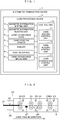
- the card processing device 1 includes a control unit 10, a magnetic information writing unit 3, a magnetic information reading unit 4, a card conveyance path 5, a card position sensor 6, a memory 7, a host interface 8, and a card conveyance mechanism 9.
- the control unit 10 is a processing unit that controls an overall operation of the card processing device 2, and includes a card writing control unit 11, a card reading control unit 12, and a card conveyance control unit 13.
- the card conveyance control unit 13 controls the conveyance of the magnetic card.
- the card conveyance path 5 is indicated by a broken line 5 in Fig. 2 described later, and is a path along which the magnetic card is conveyed.
- the card conveyance mechanism 9 is a mechanism for conveying the magnetic card inserted from an insertion port in the card conveyance path 5.
- the magnetic information reading unit 4 is disposed in the card conveyance path 5, and reads the magnetic information recorded on the magnetic card.
- the magnetic information writing unit 3 is disposed in the card conveyance path 5, and writes the magnetic information on the magnetic card.
- the card position sensor 6 detects a position of the magnetic card conveyed on the card conveyance path 5.
- the memory 7 is a storage unit that stores various information as the control unit 10 needs.
- the host interface 8 is an interface that is connected to an entire device of the automated transaction device 1 (such as ATM) where the card processing device 2 is provided, and transmits/receives information for the card processing device 2 to cooperate with the entire device. For example, the magnetic information read from the magnetic card is notified to the automated transaction machine via the host interface 8.
- Fig. 2 is a schematic view illustrating an internal configuration of a card processing device according to an embodiment of the present invention.
- an insertion port 20 for inserting a card 21 is provided in the front.
- the insertion port 20 has a sensor 22 for detecting that the card 21 has been inserted.
- the sensor 22 is a pressure sensor, and is disposed at a position to be pressed by the inserted card.
- Reference numeral 23 denotes a shutter, which controls an open/close state when the card is inserted or ejected.
- Reference numeral 24 denotes a pair of conveyance rollers 24 for gripping and conveying cards, and the conveyance rollers are arranged in the card conveyance direction.
- the conveyance rollers are arranged in the card conveyance direction.
- four pairs of conveyance rollers 24 are provided.
- Each of the pairs of conveyance rollers 24 includes a conveyance roller to which a rotational force of a motor is transmitted, and the other is a driven roller that rotates following the conveyance roller. There is one motor that drives the conveyance roller.
- the card conveyance control unit 13 controls a rotation (including a rotation direction and a rotation speed) and a stop of the motor.
- the conveyance path 5 includes a sensor 25 for detecting presence or absence of the card.
- the sensor 25 is an optical sensor including a light emitting unit and a light receiving unit, and the light emitting unit and the light receiving unit are disposed to face each other with the conveyance path interposed therebetween.
- Reference numeral 26 is a magnetic head that reads or writes magnetic information recorded on a magnetic stripe of the card conveyed into a main body of the card processing device 2.
- the magnetic head 26 is connected to a writing unit and a reading unit of card data.
- An illicit device 27 is a small device attached near the card conveyance path in the main body of the card processing device 2 as illustrated in Fig. 2 .
- the illicit device 27 is provided with a magnetic head, a memory and the like. In a case where the illicit device is attached, the magnetic information of the magnetic card 21 is illicitly read when the magnetic card 21 passes through the illicit device.
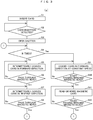
- FIG. 3 is a flowchart of an operation of reading or writing card information of the magnetic card 21 while obstructing reading of card information of the illicit device 27 at the time of card insertion.
- step S1 When the card is inserted into the card processing device 2 by a customer or the like (step S1), the card processing device 2 detects the insertion of the magnetic card 21 (step S2) and opens a shutter 23 (step S3). Whether the number of intermittent conveyance executed so far is less than a predetermined number (N times) or not is determined (step S4), and if the number is less than the predetermined number of times (in the case of No in step S4), the motor is rotated in a forward direction (a direction in which the magnetic card 21 is taken in from the insertion port 20) to intermittently convey the card in the forward direction (step S5).
- a forward direction a direction in which the magnetic card 21 is taken in from the insertion port 20
- the "intermittent conveyance” refers to conveying the card while repeating driving and stopping the motor in the forward direction or driving the motor in reverse direction (a direction in which the magnetic card 21 is ejected from an inside of the device to the insertion port). Further, a conveyance performed at a predetermined constant speed is called a constant speed conveyance, compared to the intermittent conveyance.
- the conveyance condition of the magnetic card 21 is monitored by the sensor 25, and when the magnetic card 21 passes through the magnetic head 26 (YES in step S6), the magnetic card 21 is intermittently conveyed in the reverse direction (step S7).
- the process returns to step S4 when the magnetic card 21 passes through the magnetic head 26 (Yes in step S8), the number of executions of a series of the intermittent conveyance processing in steps S5 to S8 performed so far is checked, and the above-mentioned process is repeatedly performed if the number is less than a predetermined number (No in step S4).
- the above-mentioned "the magnetic card 21 passes through the magnetic head 26" means that the magnetic card 21 is conveyed on the magnetic head 26 and a rear end of the card 21 in the conveyance direction exceeds a position of the magnetic head 26.
- the magnetic card 21 is conveyed in the forward direction at a constant speed (step S9).
- the magnetic information of the magnetic card is read or written until the magnetic card finish passing through the magnetic head 26 (steps S11 and S12).
- step S13 the card is intermittently conveyed in the reverse direction (step S13).
- step S14 the magnetic card 21 is intermittently conveyed until it passes through the magnetic head 26 again in the forward direction (steps S15 and S16). If the intermittent conveyance process (referred to as a second intermittent conveyance process) defined in the above-described steps S13 to S16 exceeds a predetermined number of times (M times) set in the card processing device 2 (Yes in step S17), the motor is stopped (step S18).
- M times predetermined number of times
- the card processing device 2 checks the card position by the sensor 25 while driving the motor, whereby it is possible to read or write the magnetic information of the magnetic card 21 by the magnetic head 27 at the timing when the magnetic card 21 is not intermittently conveyed (steps S9 to S12).
- the illicit device 26 cannot know the card position and the card conveyance direction, it cannot determine an appropriate timing for reading the magnetic card 21. Therefore, even when the card is being conveyed intermittently, the magnetic information of the magnetic card 21 is acquired, and correct magnetic information cannot be read.
- switching of the conveyance direction is performed immediately after the magnetic card 21 completely passes through the magnetic head, in both the first intermittent conveyance process and the second intermittent conveyance process, that is, although the conveyance direction is switched at the timing when the magnetic card 21 is intermittently conveyed a distance corresponding to an entire length of the magnetic card 21 in the conveyance direction with respect to the magnetic head 26 but is not limited thereto, and the conveyance direction may be switched at the timing when the magnetic card 21 is intermittently conveyed a distance longer than the entire length of the magnetic card or the conveyance direction may be switched at the timing when the magnetic card 21 is intermittently conveyed a distance shorter than the entire length of the magnetic card.
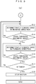
- Fig. 4(a) is a flow chart for explaining a process in the second embodiment.
- the card processing device 2 opens the shutter 23 (step S33), sets a card conveyance speed (step S34), and performs a speed change conveyance on the magnetic card in the forward direction (the direction in which the magnetic card 21 is taken in from the insertion port 20) (step S35).
- the card is not always conveyed at a constant speed, but the conveyance speed is changed little by little and conveyed. In particular, it is desirable to perform the speed change conveyance while the magnetic head 26 reads the magnetic card 21.
- the card conveyance speed is set in a table, as shown in Fig. 5 , so that 2.0x speed (S51), 1.4x speed (S52), 1.0x speed (S53), 0.7x speed (S54) and 0.5x speed (S55) may be selected, and the card is conveyed at the speed designated in the table. This is called a speed change conveyance.
- the table is not limited to the example shown in Fig. 5 and may be any value in the range of 0.5 to 2 times a normal constant speed.
- the card processing device 2 acquires a magnetic signal from the magnetic head 26 (step S36), converts the magnetic signal according to the card conveyance speed, and reads the converted magnetic signal into the magnetic information (step S37). After the card passes through the magnetic head 26 (step S38), the motor is stopped (step S39).
- the card conveyance speed is not constant at least while the magnetic head 26 reads the magnetic card 21, even if the illicit device 27 acquires magnetic data from the magnetic card 21, the illicit device 27 cannot recognize (decodes) the acquired magnetic data as a significant signal.
- the card processing device 2 sets the conveyance speed by itself, the card processing device 2 can obtain a correct data signal by performing decoding in consideration of the conveyance speed.
- FIG. 4(b) is a flow in the case of writing the data to the magnetic card 21 by the speed change conveyance.
- the card processing device 2 opens the shutter 23 (step S42), sets the card conveyance speed (step S44), and performs the speed change conveyance on the card in the forward direction (step S45). Then, the card processing device 2 writes the magnetic information from the magnetic head to the magnetic card 21 according to the card conveyance speed (step S46) . After the card passes through the magnetic head 26 (step S47), the motor is stopped (step S48).
Landscapes
- Engineering & Computer Science (AREA)
- Physics & Mathematics (AREA)
- General Physics & Mathematics (AREA)
- Theoretical Computer Science (AREA)
- Business, Economics & Management (AREA)
- Computer Vision & Pattern Recognition (AREA)
- Computer Networks & Wireless Communication (AREA)
- Accounting & Taxation (AREA)
- Toxicology (AREA)
- Artificial Intelligence (AREA)
- Health & Medical Sciences (AREA)
- Computer Security & Cryptography (AREA)
- General Health & Medical Sciences (AREA)
- Electromagnetism (AREA)
- Finance (AREA)
- Microelectronics & Electronic Packaging (AREA)
- Strategic Management (AREA)
- General Business, Economics & Management (AREA)
- Conveying Record Carriers (AREA)
- Control Of Vending Devices And Auxiliary Devices For Vending Devices (AREA)
Abstract
Description
- The present invention relates to a card processing device that takes in a magnetic card and performs processing.
- An automated transaction device such as an automated transaction machine (ATM) is equipped with a card processing device that performs an information processing with respect to a magnetic card. The card processing device takes the magnetic card inserted from a card insertion port into a main body, reads magnetic information recorded on a magnetic stripe of the magnetic card with a magnetic head, and writes the information. Then, after the transaction ends, the magnetic card is ejected from an inside of the main body to the card insertion port.
- There is a crime called skimming in which an illicit device with a magnetic head or a fake card insertion/ejection port equipped with a magnetic sensor is installed to cover a legitimate card insertion/ejection port of the ATM and illicitly acquire magnetic information of a magnetic card. The illicit device may be installed inside the main body of the card processing device.
- The illicit device is attached at a position where the magnetic stripe of the card of the card processing device passes, and in a case where a user inserts the magnetic card from the insertion port of the card processing device, when the magnetic card passes through the illicit device, the illicit device can illicitly read the magnetic information recorded on the magnetic card.
- As a measure to prevent skimming of the illicit device installed in front of the card insertion port, when the card is inserted into and ejected from the main body of the card processing device, that is, when a part of the card protrudes to the front of the card processing device, there are techniques for preventing the illicit device from reading the magnetic information of the magnetic card by repeating card conveyance, stop, or reverse conveyance (for example,
Patent Documents 1 to 3). -
- Patent Document 1:
US 6460771 B1 - Patent Document 2:
JP 2004-171205 A - Patent Document 3:
JP 2001-22894 A - In the case of illicitness measures described in
Patent Documents - An object of the present invention is to provide a technique in which illicit information reading of a magnetic card of an illicit device mounted inside a main body such as a card conveyance path of a card processing device is prevented, and the card processing device itself reads and writes magnetic information of the magnetic card.
- A card processing device includes: a conveyance path in which a plurality of pairs of conveyance rollers for gripping and conveying a card are arranged in a conveyance direction of the card; a card conveyance control means that controls conveyance of the card in the card conveyance path by controlling rotation of the conveyance roller; and a means that reads magnetic information of a magnetic card recorded on a card being conveyed on the card conveyance path, in which the card is intermittently conveyed from a front side to a back side in a main body of the card processing device, the conveyance is stopped, and the magnetic card is read at a predetermined timing during a series of processes in which the card is intermittently conveyed in reverse direction to suppress reading of a magnetic card of an illicit device. Further, the card processing device is configured such that the device reads and writes card information correctly while preventing reading of card information from the illicit device by combining a configuration of conveying the card while switching a conveyance speed to a plurality of speeds.
- The card processing device can read and write the card information of the magnetic card while obstructing the illicit device installed in the main body of the card processing device reading the magnetic information of the magnetic card.
-
-
Fig. 1 is a block diagram of an automated transaction device and a card processing device according to an embodiment of the present invention. -
Fig. 2 is a schematic view of an internal configuration of a card processing device according to an embodiment of the present invention. -
Fig. 3(a) is a flow chart illustrating an operation of a card processing device in a first embodiment of the present invention. -
Fig. 3(b) is a flowchart illustrating the operation of the card processing device in the first embodiment of the present invention. -
Fig. 4(a) is a flow chart illustrating an operation of a card processing device in a second embodiment of the present invention. -
Fig. 4(b) is a flow chart illustrating the operation of the card processing device in the second embodiment of the present invention. -
Fig. 5 is a table showing card conveyance speeds of the card processing device in the second embodiment of the present invention. - Embodiments of the present invention will be described using the drawings.
- As illustrated in
Fig. 1 , acard processing device 2 according to an embodiment of the present invention is mounted on anautomated transaction device 1. That is, anautomated transaction device 1 includes acard processing device 2. Theautomated transaction device 1 is, for example, an automated transaction machine (ATM). The ATM includes, in addition to thecard processing device 2, a bill processing unit and a coin processing unit for processing bills and coins, a customer operation unit by which a customer carries out transaction operations, and the like, which are omitted here. - The
card processing device 1 includes acontrol unit 10, a magneticinformation writing unit 3, a magneticinformation reading unit 4, acard conveyance path 5, acard position sensor 6, amemory 7, ahost interface 8, and acard conveyance mechanism 9. - The
control unit 10 is a processing unit that controls an overall operation of thecard processing device 2, and includes a cardwriting control unit 11, a cardreading control unit 12, and a cardconveyance control unit 13. The cardconveyance control unit 13 controls the conveyance of the magnetic card. - The
card conveyance path 5 is indicated by abroken line 5 inFig. 2 described later, and is a path along which the magnetic card is conveyed. Thecard conveyance mechanism 9 is a mechanism for conveying the magnetic card inserted from an insertion port in thecard conveyance path 5. The magneticinformation reading unit 4 is disposed in thecard conveyance path 5, and reads the magnetic information recorded on the magnetic card. The magneticinformation writing unit 3 is disposed in thecard conveyance path 5, and writes the magnetic information on the magnetic card. - The
card position sensor 6 detects a position of the magnetic card conveyed on thecard conveyance path 5. Thememory 7 is a storage unit that stores various information as thecontrol unit 10 needs. Thehost interface 8 is an interface that is connected to an entire device of the automated transaction device 1 (such as ATM) where thecard processing device 2 is provided, and transmits/receives information for thecard processing device 2 to cooperate with the entire device. For example, the magnetic information read from the magnetic card is notified to the automated transaction machine via thehost interface 8. -
Fig. 2 is a schematic view illustrating an internal configuration of a card processing device according to an embodiment of the present invention. In thecard processing device 2 of this embodiment, aninsertion port 20 for inserting acard 21 is provided in the front. Theinsertion port 20 has asensor 22 for detecting that thecard 21 has been inserted. Thesensor 22 is a pressure sensor, and is disposed at a position to be pressed by the inserted card.Reference numeral 23 denotes a shutter, which controls an open/close state when the card is inserted or ejected. -
Reference numeral 24 denotes a pair ofconveyance rollers 24 for gripping and conveying cards, and the conveyance rollers are arranged in the card conveyance direction. In the present embodiment, four pairs ofconveyance rollers 24 are provided. Each of the pairs ofconveyance rollers 24 includes a conveyance roller to which a rotational force of a motor is transmitted, and the other is a driven roller that rotates following the conveyance roller. There is one motor that drives the conveyance roller. - The card
conveyance control unit 13 controls a rotation (including a rotation direction and a rotation speed) and a stop of the motor. Theconveyance path 5 includes asensor 25 for detecting presence or absence of the card. Thesensor 25 is an optical sensor including a light emitting unit and a light receiving unit, and the light emitting unit and the light receiving unit are disposed to face each other with the conveyance path interposed therebetween. -
Reference numeral 26 is a magnetic head that reads or writes magnetic information recorded on a magnetic stripe of the card conveyed into a main body of thecard processing device 2. Themagnetic head 26 is connected to a writing unit and a reading unit of card data. - An
illicit device 27 is a small device attached near the card conveyance path in the main body of thecard processing device 2 as illustrated inFig. 2 . Theillicit device 27 is provided with a magnetic head, a memory and the like. In a case where the illicit device is attached, the magnetic information of themagnetic card 21 is illicitly read when themagnetic card 21 passes through the illicit device. - Hereinafter, an operation of the
card processing device 2 of the present embodiment will be described.Fig. 3 is a flowchart of an operation of reading or writing card information of themagnetic card 21 while obstructing reading of card information of theillicit device 27 at the time of card insertion. - When the card is inserted into the
card processing device 2 by a customer or the like (step S1), thecard processing device 2 detects the insertion of the magnetic card 21 (step S2) and opens a shutter 23 (step S3). Whether the number of intermittent conveyance executed so far is less than a predetermined number (N times) or not is determined (step S4), and if the number is less than the predetermined number of times (in the case of No in step S4), the motor is rotated in a forward direction (a direction in which themagnetic card 21 is taken in from the insertion port 20) to intermittently convey the card in the forward direction (step S5). - Here, the "intermittent conveyance" refers to conveying the card while repeating driving and stopping the motor in the forward direction or driving the motor in reverse direction (a direction in which the
magnetic card 21 is ejected from an inside of the device to the insertion port). Further, a conveyance performed at a predetermined constant speed is called a constant speed conveyance, compared to the intermittent conveyance. - The conveyance condition of the
magnetic card 21 is monitored by thesensor 25, and when themagnetic card 21 passes through the magnetic head 26 (YES in step S6), themagnetic card 21 is intermittently conveyed in the reverse direction (step S7). The process returns to step S4 when themagnetic card 21 passes through the magnetic head 26 (Yes in step S8), the number of executions of a series of the intermittent conveyance processing in steps S5 to S8 performed so far is checked, and the above-mentioned process is repeatedly performed if the number is less than a predetermined number (No in step S4). The above-mentioned "themagnetic card 21 passes through themagnetic head 26" means that themagnetic card 21 is conveyed on themagnetic head 26 and a rear end of thecard 21 in the conveyance direction exceeds a position of themagnetic head 26. - Here, when the intermittent conveyance process (referred to as the first intermittent conveyance process) defined in S5 to S8 exceeds the predetermined number of times (N times) (Yes in step S4), the
magnetic card 21 is conveyed in the forward direction at a constant speed (step S9). When themagnetic card 21 starts passing through the magnetic head 26 (Yes in step S10), the magnetic information of the magnetic card is read or written until the magnetic card finish passing through the magnetic head 26 (steps S11 and S12). - Next, the card is intermittently conveyed in the reverse direction (step S13). After passing through the magnetic head 26 (Yes in step S14), the
magnetic card 21 is intermittently conveyed until it passes through themagnetic head 26 again in the forward direction (steps S15 and S16). If the intermittent conveyance process (referred to as a second intermittent conveyance process) defined in the above-described steps S13 to S16 exceeds a predetermined number of times (M times) set in the card processing device 2 (Yes in step S17), the motor is stopped (step S18). - By performing the conveyance control as described above, the
card processing device 2 checks the card position by thesensor 25 while driving the motor, whereby it is possible to read or write the magnetic information of themagnetic card 21 by themagnetic head 27 at the timing when themagnetic card 21 is not intermittently conveyed (steps S9 to S12). However, since theillicit device 26 cannot know the card position and the card conveyance direction, it cannot determine an appropriate timing for reading themagnetic card 21. Therefore, even when the card is being conveyed intermittently, the magnetic information of themagnetic card 21 is acquired, and correct magnetic information cannot be read. - In the above description, switching of the conveyance direction is performed immediately after the
magnetic card 21 completely passes through the magnetic head, in both the first intermittent conveyance process and the second intermittent conveyance process, that is, although the conveyance direction is switched at the timing when themagnetic card 21 is intermittently conveyed a distance corresponding to an entire length of themagnetic card 21 in the conveyance direction with respect to themagnetic head 26 but is not limited thereto, and the conveyance direction may be switched at the timing when themagnetic card 21 is intermittently conveyed a distance longer than the entire length of the magnetic card or the conveyance direction may be switched at the timing when themagnetic card 21 is intermittently conveyed a distance shorter than the entire length of the magnetic card. - Hereinafter, an operation of the
card processing device 2 of the present embodiment will be described.Fig. 4(a) is a flow chart for explaining a process in the second embodiment. As illustrated inFig. 4 , when detecting the insertion of the magnetic card 21 (steps S31 and S32), thecard processing device 2 opens the shutter 23 (step S33), sets a card conveyance speed (step S34), and performs a speed change conveyance on the magnetic card in the forward direction (the direction in which themagnetic card 21 is taken in from the insertion port 20) (step S35). - That is, after the
magnetic card 21 is taken into thecard processing device 2, the card is not always conveyed at a constant speed, but the conveyance speed is changed little by little and conveyed. In particular, it is desirable to perform the speed change conveyance while themagnetic head 26 reads themagnetic card 21. - The card conveyance speed is set in a table, as shown in
Fig. 5 , so that 2.0x speed (S51), 1.4x speed (S52), 1.0x speed (S53), 0.7x speed (S54) and 0.5x speed (S55) may be selected, and the card is conveyed at the speed designated in the table. This is called a speed change conveyance. - For example, assuming that a period during which the
magnetic head 26 reads themagnetic card 21 is T (sec), the card is conveyed at the 2.0x speed (S51) during the first T1 (sec), conveyed at the 1.4x speed (S52) during the subsequent T2 (sec), conveyed at the 1.0x speed (S53) during the subsequent T3 (sec), conveyed at the 0.7x speed (S54) during the subsequent T4 (sec), and conveyed at the 0.5x speed (S55) during the last T5 (sec) (T = T1 + T2 + T3 + T4 + T5). The table is not limited to the example shown inFig. 5 and may be any value in the range of 0.5 to 2 times a normal constant speed. - Then, the
card processing device 2 acquires a magnetic signal from the magnetic head 26 (step S36), converts the magnetic signal according to the card conveyance speed, and reads the converted magnetic signal into the magnetic information (step S37). After the card passes through the magnetic head 26 (step S38), the motor is stopped (step S39). - As described above, since the card conveyance speed is not constant at least while the
magnetic head 26 reads themagnetic card 21, even if theillicit device 27 acquires magnetic data from themagnetic card 21, theillicit device 27 cannot recognize (decodes) the acquired magnetic data as a significant signal. On the other hand, since thecard processing device 2 sets the conveyance speed by itself, thecard processing device 2 can obtain a correct data signal by performing decoding in consideration of the conveyance speed. - Writing to the magnetic card may also be realized in the same way.
Fig. 4(b) is a flow in the case of writing the data to themagnetic card 21 by the speed change conveyance. When detecting the insertion of the magnetic card 21 (step S41), thecard processing device 2 opens the shutter 23 (step S42), sets the card conveyance speed (step S44), and performs the speed change conveyance on the card in the forward direction (step S45). Then, thecard processing device 2 writes the magnetic information from the magnetic head to themagnetic card 21 according to the card conveyance speed (step S46) . After the card passes through the magnetic head 26 (step S47), the motor is stopped (step S48). - Even in a case where the processes of the first embodiment and the second embodiment described above are performed independently of each other, it is possible to prevent illicit reading of the magnetic card data by the illicit device, but it is possible to more securely prevent the illicit reading of the magnetic card data by combining the respective embodiments.
-
- 1
- Automated transaction device
- 2
- Card processing device
- 3
- Magnetic information writing unit
- 4
- Magnetic information reading unit
- 5
- Card conveyance path
- 6
- Card position sensor
- 7
- Memory
- 8
- Host interface
- 9
- Card conveyance mechanism
- 10
- Control unit
- 11
- Card writing control unit
- 12
- Card reading control unit
- 13
- Card conveyance control unit
- 21
- Magnetic card
- 22
- Insertion detection sensor
- 23
- Shutter
- 24
- Roller
- 25
- Sensor
- 26
- Magnetic head
- 27
- Illicit device
Claims (7)
- A card processing device including an insertion/ejection port through which a card is inserted and ejected, a conveyance path through which the inserted card is conveyed to a predetermined position, a magnetic head provided on the conveyance path and reading magnetic information of the card by conveying the card, and a control unit that controls the conveyance of the card and the reading of the magnetic information,
wherein the control unit reads or writes information of the card by sequentially performing processings including:a first intermittent conveyance processing in which the inserted card is intermittently conveyed until the inserted card passes through the magnetic head and then the inserted card is intermittently conveyed until the inserted card passes through the magnetic head in reverse direction;a magnetic data reading and writing processing in which the card is conveyed at a constant speed from the insertion port toward an inside of the card processing device such that the magnetic head reads or writes the magnetic information of the card; anda second intermittent conveyance processing in which the card is intermittently conveyed until the card passes through the magnetic head in a direction from the inside of the card processing device toward the insertion port and then the card is intermittently conveyed until the card passes through the magnetic head in reverse direction. - The card processing device according to claim 1, wherein each of the first intermittent conveyance processing and the second intermittent conveyance processing is performed one or more arbitrary times.
- The card processing device according to claim 1 or 2,
wherein switching of a conveyance direction in the first intermittent conveyance processing or the second intermittent conveyance process is performed at a timing when the card is conveyed a distance shorter than an entire length of the card in the conveyance direction. - The card processing device according to claim 1 or 2,
wherein switching of a conveyance direction in the first intermittent conveyance processing or the second intermittent conveyance process is performed at a timing when the card is conveyed a distance longer than an entire length of the card in the conveyance direction. - The card processing device according to any one of claims 1 to 4,
wherein in the magnetic data reading and writing processing, the card is conveyed while being varied in a speed with a plurality of predetermined speeds from the insertion port toward the inside of the card processing device such that the magnetic head reads or writes the magnetic information of the card. - A card processing device including an insertion/ejection port through which a card is inserted and ejected, a conveyance path through which the inserted card is conveyed to a predetermined position, a magnetic head provided on the conveyance path and reading magnetic information of the card by conveying the card, and a control unit that controls the conveyance of the card and the reading of the magnetic information,
wherein the control unit performs a magnetic data reading and writing processing in which the card is conveyed while being varied in a speed with a plurality of predetermined speeds from the insertion port toward an inside of the card processing device such that the magnetic head reads or writes the magnetic information of the card. - An automated transaction device equipped with the card processing device according to any one of claims 1 to 6.
Applications Claiming Priority (2)
| Application Number | Priority Date | Filing Date | Title |
|---|---|---|---|
| JP2017069585A JP6820786B2 (en) | 2017-03-31 | 2017-03-31 | Card processing equipment, automated teller machines |
| PCT/JP2017/040197 WO2018179565A1 (en) | 2017-03-31 | 2017-11-08 | Card processing device and automated transaction device |
Publications (3)
| Publication Number | Publication Date |
|---|---|
| EP3605396A1 true EP3605396A1 (en) | 2020-02-05 |
| EP3605396A4 EP3605396A4 (en) | 2020-12-09 |
| EP3605396B1 EP3605396B1 (en) | 2023-03-22 |
Family
ID=63677806
Family Applications (1)
| Application Number | Title | Priority Date | Filing Date |
|---|---|---|---|
| EP17903546.4A Active EP3605396B1 (en) | 2017-03-31 | 2017-11-08 | Card processing device and automated transaction device |
Country Status (3)
| Country | Link |
|---|---|
| EP (1) | EP3605396B1 (en) |
| JP (1) | JP6820786B2 (en) |
| WO (1) | WO2018179565A1 (en) |
Family Cites Families (11)
| Publication number | Priority date | Publication date | Assignee | Title |
|---|---|---|---|---|
| GB9915193D0 (en) | 1999-06-29 | 1999-09-01 | Ncr Int Inc | Motorised card reader module |
| JP3806271B2 (en) | 1999-07-09 | 2006-08-09 | 日本電産サンキョー株式会社 | Magnetic card transaction device |
| JP3801976B2 (en) | 2002-11-19 | 2006-07-26 | 日立オムロンターミナルソリューションズ株式会社 | Card processing device |
| JP4522072B2 (en) * | 2003-10-22 | 2010-08-11 | 日立オムロンターミナルソリューションズ株式会社 | Card processing device |
| CA2621850C (en) * | 2005-09-09 | 2013-01-08 | Diebold, Incorporated | Automated banking machine anti-skimming card reader |
| JP4680048B2 (en) * | 2005-12-13 | 2011-05-11 | 日立オムロンターミナルソリューションズ株式会社 | Card processing device |
| JP4778368B2 (en) * | 2006-07-04 | 2011-09-21 | エヌイーシーコンピュータテクノ株式会社 | Card reader / writer, method for preventing unauthorized reading of card reader / writer, ATM device |
| JP5030678B2 (en) * | 2007-06-15 | 2012-09-19 | 日立オムロンターミナルソリューションズ株式会社 | Recording medium processing apparatus |
| JP5210900B2 (en) * | 2009-01-23 | 2013-06-12 | 日立オムロンターミナルソリューションズ株式会社 | Transaction processing equipment |
| US9373114B2 (en) * | 2011-02-25 | 2016-06-21 | Diebold Self-Service Systems Division Of Diebold, Incorporated | Automated teller machine with an encrypting card reader and an encrypting pin pad |
| JP6225738B2 (en) * | 2014-02-14 | 2017-11-08 | 沖電気工業株式会社 | Automatic transaction equipment |
-
2017
- 2017-03-31 JP JP2017069585A patent/JP6820786B2/en active Active
- 2017-11-08 WO PCT/JP2017/040197 patent/WO2018179565A1/en not_active Ceased
- 2017-11-08 EP EP17903546.4A patent/EP3605396B1/en active Active
Also Published As
| Publication number | Publication date |
|---|---|
| WO2018179565A1 (en) | 2018-10-04 |
| JP6820786B2 (en) | 2021-01-27 |
| EP3605396B1 (en) | 2023-03-22 |
| EP3605396A4 (en) | 2020-12-09 |
| JP2018173684A (en) | 2018-11-08 |
Similar Documents
| Publication | Publication Date | Title |
|---|---|---|
| JP4680048B2 (en) | Card processing device | |
| US6851613B2 (en) | Card processor | |
| WO2005041116A1 (en) | Card processing device | |
| KR101041205B1 (en) | Conveying direction switching device and paper sheet conveying device | |
| US5545884A (en) | Card reader apparatus | |
| EP3605396B1 (en) | Card processing device and automated transaction device | |
| JP2022097304A (en) | Booklet transport device, booklet transport method and booklet transport program | |
| KR101834494B1 (en) | Apparatus and Method for Auto Turn of Passbook Page in Financial Device | |
| US20210272408A1 (en) | Transaction device | |
| JP7330511B2 (en) | Automatic transaction device, preventive rewriting method, program | |
| JP2007226340A (en) | Card reader | |
| JP4778368B2 (en) | Card reader / writer, method for preventing unauthorized reading of card reader / writer, ATM device | |
| JP2725431B2 (en) | Banknote recognition device with card | |
| CN103021070B (en) | Automatic transaction device and medium conveying method | |
| JP2005107763A (en) | Device for paper sheet discrimination | |
| CN102113029A (en) | Automatic transaction device | |
| JP2003271906A (en) | Medium processing device and medium processing method | |
| JP2002133484A (en) | Media reader | |
| JP2003091765A (en) | Form processing device, form processing method, and automatic transaction device | |
| JP2009140276A (en) | Automatic transaction apparatus | |
| JP2005173947A (en) | Card handling device | |
| JP5262205B2 (en) | Automatic transaction equipment | |
| JP6492984B2 (en) | Automatic transaction equipment | |
| JP2003034058A (en) | Form processing device and form processing method | |
| CN108470395A (en) | Pop up adding window and non-adding window medium |
Legal Events
| Date | Code | Title | Description |
|---|---|---|---|
| STAA | Information on the status of an ep patent application or granted ep patent |
Free format text: STATUS: THE INTERNATIONAL PUBLICATION HAS BEEN MADE |
|
| PUAI | Public reference made under article 153(3) epc to a published international application that has entered the european phase |
Free format text: ORIGINAL CODE: 0009012 |
|
| STAA | Information on the status of an ep patent application or granted ep patent |
Free format text: STATUS: REQUEST FOR EXAMINATION WAS MADE |
|
| 17P | Request for examination filed |
Effective date: 20191031 |
|
| AK | Designated contracting states |
Kind code of ref document: A1 Designated state(s): AL AT BE BG CH CY CZ DE DK EE ES FI FR GB GR HR HU IE IS IT LI LT LU LV MC MK MT NL NO PL PT RO RS SE SI SK SM TR |
|
| AX | Request for extension of the european patent |
Extension state: BA ME |
|
| DAV | Request for validation of the european patent (deleted) | ||
| DAX | Request for extension of the european patent (deleted) | ||
| A4 | Supplementary search report drawn up and despatched |
Effective date: 20201110 |
|
| RIC1 | Information provided on ipc code assigned before grant |
Ipc: G06K 7/08 20060101ALI20201104BHEP Ipc: G07F 19/00 20060101ALI20201104BHEP Ipc: G07D 9/00 20060101ALI20201104BHEP Ipc: G06K 7/10 20060101ALI20201104BHEP Ipc: G06K 13/08 20060101ALI20201104BHEP Ipc: G06K 13/06 20060101AFI20201104BHEP |
|
| STAA | Information on the status of an ep patent application or granted ep patent |
Free format text: STATUS: EXAMINATION IS IN PROGRESS |
|
| 17Q | First examination report despatched |
Effective date: 20211011 |
|
| 17Q | First examination report despatched |
Effective date: 20211022 |
|
| RAP3 | Party data changed (applicant data changed or rights of an application transferred) |
Owner name: HITACHI CHANNEL SOLUTIONS, CORP. |
|
| GRAP | Despatch of communication of intention to grant a patent |
Free format text: ORIGINAL CODE: EPIDOSNIGR1 |
|
| STAA | Information on the status of an ep patent application or granted ep patent |
Free format text: STATUS: GRANT OF PATENT IS INTENDED |
|
| INTG | Intention to grant announced |
Effective date: 20221202 |
|
| GRAS | Grant fee paid |
Free format text: ORIGINAL CODE: EPIDOSNIGR3 |
|
| GRAA | (expected) grant |
Free format text: ORIGINAL CODE: 0009210 |
|
| STAA | Information on the status of an ep patent application or granted ep patent |
Free format text: STATUS: THE PATENT HAS BEEN GRANTED |
|
| AK | Designated contracting states |
Kind code of ref document: B1 Designated state(s): AL AT BE BG CH CY CZ DE DK EE ES FI FR GB GR HR HU IE IS IT LI LT LU LV MC MK MT NL NO PL PT RO RS SE SI SK SM TR |
|
| REG | Reference to a national code |
Ref country code: GB Ref legal event code: FG4D |
|
| REG | Reference to a national code |
Ref country code: CH Ref legal event code: EP |
|
| REG | Reference to a national code |
Ref country code: IE Ref legal event code: FG4D |
|
| REG | Reference to a national code |
Ref country code: DE Ref legal event code: R096 Ref document number: 602017067112 Country of ref document: DE |
|
| REG | Reference to a national code |
Ref country code: AT Ref legal event code: REF Ref document number: 1555761 Country of ref document: AT Kind code of ref document: T Effective date: 20230415 |
|
| REG | Reference to a national code |
Ref country code: LT Ref legal event code: MG9D |
|
| REG | Reference to a national code |
Ref country code: NL Ref legal event code: MP Effective date: 20230322 |
|
| PG25 | Lapsed in a contracting state [announced via postgrant information from national office to epo] |
Ref country code: RS Free format text: LAPSE BECAUSE OF FAILURE TO SUBMIT A TRANSLATION OF THE DESCRIPTION OR TO PAY THE FEE WITHIN THE PRESCRIBED TIME-LIMIT Effective date: 20230322 Ref country code: NO Free format text: LAPSE BECAUSE OF FAILURE TO SUBMIT A TRANSLATION OF THE DESCRIPTION OR TO PAY THE FEE WITHIN THE PRESCRIBED TIME-LIMIT Effective date: 20230622 Ref country code: LV Free format text: LAPSE BECAUSE OF FAILURE TO SUBMIT A TRANSLATION OF THE DESCRIPTION OR TO PAY THE FEE WITHIN THE PRESCRIBED TIME-LIMIT Effective date: 20230322 Ref country code: LT Free format text: LAPSE BECAUSE OF FAILURE TO SUBMIT A TRANSLATION OF THE DESCRIPTION OR TO PAY THE FEE WITHIN THE PRESCRIBED TIME-LIMIT Effective date: 20230322 Ref country code: HR Free format text: LAPSE BECAUSE OF FAILURE TO SUBMIT A TRANSLATION OF THE DESCRIPTION OR TO PAY THE FEE WITHIN THE PRESCRIBED TIME-LIMIT Effective date: 20230322 |
|
| REG | Reference to a national code |
Ref country code: AT Ref legal event code: MK05 Ref document number: 1555761 Country of ref document: AT Kind code of ref document: T Effective date: 20230322 |
|
| PG25 | Lapsed in a contracting state [announced via postgrant information from national office to epo] |
Ref country code: SE Free format text: LAPSE BECAUSE OF FAILURE TO SUBMIT A TRANSLATION OF THE DESCRIPTION OR TO PAY THE FEE WITHIN THE PRESCRIBED TIME-LIMIT Effective date: 20230322 Ref country code: NL Free format text: LAPSE BECAUSE OF FAILURE TO SUBMIT A TRANSLATION OF THE DESCRIPTION OR TO PAY THE FEE WITHIN THE PRESCRIBED TIME-LIMIT Effective date: 20230322 Ref country code: GR Free format text: LAPSE BECAUSE OF FAILURE TO SUBMIT A TRANSLATION OF THE DESCRIPTION OR TO PAY THE FEE WITHIN THE PRESCRIBED TIME-LIMIT Effective date: 20230623 Ref country code: FI Free format text: LAPSE BECAUSE OF FAILURE TO SUBMIT A TRANSLATION OF THE DESCRIPTION OR TO PAY THE FEE WITHIN THE PRESCRIBED TIME-LIMIT Effective date: 20230322 |
|
| PG25 | Lapsed in a contracting state [announced via postgrant information from national office to epo] |
Ref country code: SM Free format text: LAPSE BECAUSE OF FAILURE TO SUBMIT A TRANSLATION OF THE DESCRIPTION OR TO PAY THE FEE WITHIN THE PRESCRIBED TIME-LIMIT Effective date: 20230322 Ref country code: RO Free format text: LAPSE BECAUSE OF FAILURE TO SUBMIT A TRANSLATION OF THE DESCRIPTION OR TO PAY THE FEE WITHIN THE PRESCRIBED TIME-LIMIT Effective date: 20230322 Ref country code: PT Free format text: LAPSE BECAUSE OF FAILURE TO SUBMIT A TRANSLATION OF THE DESCRIPTION OR TO PAY THE FEE WITHIN THE PRESCRIBED TIME-LIMIT Effective date: 20230724 Ref country code: ES Free format text: LAPSE BECAUSE OF FAILURE TO SUBMIT A TRANSLATION OF THE DESCRIPTION OR TO PAY THE FEE WITHIN THE PRESCRIBED TIME-LIMIT Effective date: 20230322 Ref country code: EE Free format text: LAPSE BECAUSE OF FAILURE TO SUBMIT A TRANSLATION OF THE DESCRIPTION OR TO PAY THE FEE WITHIN THE PRESCRIBED TIME-LIMIT Effective date: 20230322 Ref country code: AT Free format text: LAPSE BECAUSE OF FAILURE TO SUBMIT A TRANSLATION OF THE DESCRIPTION OR TO PAY THE FEE WITHIN THE PRESCRIBED TIME-LIMIT Effective date: 20230322 |
|
| PG25 | Lapsed in a contracting state [announced via postgrant information from national office to epo] |
Ref country code: SK Free format text: LAPSE BECAUSE OF FAILURE TO SUBMIT A TRANSLATION OF THE DESCRIPTION OR TO PAY THE FEE WITHIN THE PRESCRIBED TIME-LIMIT Effective date: 20230322 Ref country code: PL Free format text: LAPSE BECAUSE OF FAILURE TO SUBMIT A TRANSLATION OF THE DESCRIPTION OR TO PAY THE FEE WITHIN THE PRESCRIBED TIME-LIMIT Effective date: 20230322 Ref country code: IS Free format text: LAPSE BECAUSE OF FAILURE TO SUBMIT A TRANSLATION OF THE DESCRIPTION OR TO PAY THE FEE WITHIN THE PRESCRIBED TIME-LIMIT Effective date: 20230722 |
|
| REG | Reference to a national code |
Ref country code: DE Ref legal event code: R097 Ref document number: 602017067112 Country of ref document: DE |
|
| PLBE | No opposition filed within time limit |
Free format text: ORIGINAL CODE: 0009261 |
|
| STAA | Information on the status of an ep patent application or granted ep patent |
Free format text: STATUS: NO OPPOSITION FILED WITHIN TIME LIMIT |
|
| PG25 | Lapsed in a contracting state [announced via postgrant information from national office to epo] |
Ref country code: SI Free format text: LAPSE BECAUSE OF FAILURE TO SUBMIT A TRANSLATION OF THE DESCRIPTION OR TO PAY THE FEE WITHIN THE PRESCRIBED TIME-LIMIT Effective date: 20230322 Ref country code: DK Free format text: LAPSE BECAUSE OF FAILURE TO SUBMIT A TRANSLATION OF THE DESCRIPTION OR TO PAY THE FEE WITHIN THE PRESCRIBED TIME-LIMIT Effective date: 20230322 Ref country code: CZ Free format text: LAPSE BECAUSE OF FAILURE TO SUBMIT A TRANSLATION OF THE DESCRIPTION OR TO PAY THE FEE WITHIN THE PRESCRIBED TIME-LIMIT Effective date: 20230322 |
|
| 26N | No opposition filed |
Effective date: 20240102 |
|
| PG25 | Lapsed in a contracting state [announced via postgrant information from national office to epo] |
Ref country code: IT Free format text: LAPSE BECAUSE OF FAILURE TO SUBMIT A TRANSLATION OF THE DESCRIPTION OR TO PAY THE FEE WITHIN THE PRESCRIBED TIME-LIMIT Effective date: 20230322 |
|
| REG | Reference to a national code |
Ref country code: CH Ref legal event code: PL |
|
| PG25 | Lapsed in a contracting state [announced via postgrant information from national office to epo] |
Ref country code: MC Free format text: LAPSE BECAUSE OF FAILURE TO SUBMIT A TRANSLATION OF THE DESCRIPTION OR TO PAY THE FEE WITHIN THE PRESCRIBED TIME-LIMIT Effective date: 20230322 |
|
| PG25 | Lapsed in a contracting state [announced via postgrant information from national office to epo] |
Ref country code: LU Free format text: LAPSE BECAUSE OF NON-PAYMENT OF DUE FEES Effective date: 20231108 |
|
| PG25 | Lapsed in a contracting state [announced via postgrant information from national office to epo] |
Ref country code: CH Free format text: LAPSE BECAUSE OF NON-PAYMENT OF DUE FEES Effective date: 20231130 |
|
| PG25 | Lapsed in a contracting state [announced via postgrant information from national office to epo] |
Ref country code: MC Free format text: LAPSE BECAUSE OF FAILURE TO SUBMIT A TRANSLATION OF THE DESCRIPTION OR TO PAY THE FEE WITHIN THE PRESCRIBED TIME-LIMIT Effective date: 20230322 Ref country code: LU Free format text: LAPSE BECAUSE OF NON-PAYMENT OF DUE FEES Effective date: 20231108 Ref country code: CH Free format text: LAPSE BECAUSE OF NON-PAYMENT OF DUE FEES Effective date: 20231130 |
|
| REG | Reference to a national code |
Ref country code: BE Ref legal event code: MM Effective date: 20231130 |
|
| REG | Reference to a national code |
Ref country code: IE Ref legal event code: MM4A |
|
| PG25 | Lapsed in a contracting state [announced via postgrant information from national office to epo] |
Ref country code: IE Free format text: LAPSE BECAUSE OF NON-PAYMENT OF DUE FEES Effective date: 20231108 |
|
| PG25 | Lapsed in a contracting state [announced via postgrant information from national office to epo] |
Ref country code: BE Free format text: LAPSE BECAUSE OF NON-PAYMENT OF DUE FEES Effective date: 20231130 |
|
| PG25 | Lapsed in a contracting state [announced via postgrant information from national office to epo] |
Ref country code: FR Free format text: LAPSE BECAUSE OF NON-PAYMENT OF DUE FEES Effective date: 20231130 |
|
| PG25 | Lapsed in a contracting state [announced via postgrant information from national office to epo] |
Ref country code: IE Free format text: LAPSE BECAUSE OF NON-PAYMENT OF DUE FEES Effective date: 20231108 Ref country code: FR Free format text: LAPSE BECAUSE OF NON-PAYMENT OF DUE FEES Effective date: 20231130 Ref country code: BE Free format text: LAPSE BECAUSE OF NON-PAYMENT OF DUE FEES Effective date: 20231130 |
|
| PG25 | Lapsed in a contracting state [announced via postgrant information from national office to epo] |
Ref country code: BG Free format text: LAPSE BECAUSE OF FAILURE TO SUBMIT A TRANSLATION OF THE DESCRIPTION OR TO PAY THE FEE WITHIN THE PRESCRIBED TIME-LIMIT Effective date: 20230322 |
|
| PG25 | Lapsed in a contracting state [announced via postgrant information from national office to epo] |
Ref country code: BG Free format text: LAPSE BECAUSE OF FAILURE TO SUBMIT A TRANSLATION OF THE DESCRIPTION OR TO PAY THE FEE WITHIN THE PRESCRIBED TIME-LIMIT Effective date: 20230322 |
|
| PG25 | Lapsed in a contracting state [announced via postgrant information from national office to epo] |
Ref country code: CY Free format text: LAPSE BECAUSE OF FAILURE TO SUBMIT A TRANSLATION OF THE DESCRIPTION OR TO PAY THE FEE WITHIN THE PRESCRIBED TIME-LIMIT; INVALID AB INITIO Effective date: 20171108 |
|
| PG25 | Lapsed in a contracting state [announced via postgrant information from national office to epo] |
Ref country code: HU Free format text: LAPSE BECAUSE OF FAILURE TO SUBMIT A TRANSLATION OF THE DESCRIPTION OR TO PAY THE FEE WITHIN THE PRESCRIBED TIME-LIMIT; INVALID AB INITIO Effective date: 20171108 |
|
| PG25 | Lapsed in a contracting state [announced via postgrant information from national office to epo] |
Ref country code: TR Free format text: LAPSE BECAUSE OF FAILURE TO SUBMIT A TRANSLATION OF THE DESCRIPTION OR TO PAY THE FEE WITHIN THE PRESCRIBED TIME-LIMIT Effective date: 20230322 |
|
| PGFP | Annual fee paid to national office [announced via postgrant information from national office to epo] |
Ref country code: DE Payment date: 20251022 Year of fee payment: 9 |
|
| PGFP | Annual fee paid to national office [announced via postgrant information from national office to epo] |
Ref country code: GB Payment date: 20251022 Year of fee payment: 9 |