EP3604949A1 - Equipment apparatus management device - Google Patents
Equipment apparatus management device Download PDFInfo
- Publication number
- EP3604949A1 EP3604949A1 EP17901624.1A EP17901624A EP3604949A1 EP 3604949 A1 EP3604949 A1 EP 3604949A1 EP 17901624 A EP17901624 A EP 17901624A EP 3604949 A1 EP3604949 A1 EP 3604949A1
- Authority
- EP
- European Patent Office
- Prior art keywords
- color
- display
- value
- facility equipment
- hue
- Prior art date
- Legal status (The legal status is an assumption and is not a legal conclusion. Google has not performed a legal analysis and makes no representation as to the accuracy of the status listed.)
- Granted
Links
Images





Classifications
-
- F—MECHANICAL ENGINEERING; LIGHTING; HEATING; WEAPONS; BLASTING
- F24—HEATING; RANGES; VENTILATING
- F24F—AIR-CONDITIONING; AIR-HUMIDIFICATION; VENTILATION; USE OF AIR CURRENTS FOR SCREENING
- F24F11/00—Control or safety arrangements
- F24F11/50—Control or safety arrangements characterised by user interfaces or communication
- F24F11/52—Indication arrangements, e.g. displays
-
- G—PHYSICS
- G06—COMPUTING OR CALCULATING; COUNTING
- G06F—ELECTRIC DIGITAL DATA PROCESSING
- G06F3/00—Input arrangements for transferring data to be processed into a form capable of being handled by the computer; Output arrangements for transferring data from processing unit to output unit, e.g. interface arrangements
- G06F3/01—Input arrangements or combined input and output arrangements for interaction between user and computer
- G06F3/048—Interaction techniques based on graphical user interfaces [GUI]
- G06F3/0484—Interaction techniques based on graphical user interfaces [GUI] for the control of specific functions or operations, e.g. selecting or manipulating an object, an image or a displayed text element, setting a parameter value or selecting a range
- G06F3/04847—Interaction techniques to control parameter settings, e.g. interaction with sliders or dials
-
- G—PHYSICS
- G09—EDUCATION; CRYPTOGRAPHY; DISPLAY; ADVERTISING; SEALS
- G09G—ARRANGEMENTS OR CIRCUITS FOR CONTROL OF INDICATING DEVICES USING STATIC MEANS TO PRESENT VARIABLE INFORMATION
- G09G5/00—Control arrangements or circuits for visual indicators common to cathode-ray tube indicators and other visual indicators
- G09G5/02—Control arrangements or circuits for visual indicators common to cathode-ray tube indicators and other visual indicators characterised by the way in which colour is displayed
- G09G5/06—Control arrangements or circuits for visual indicators common to cathode-ray tube indicators and other visual indicators characterised by the way in which colour is displayed using colour palettes, e.g. look-up tables
-
- G—PHYSICS
- G09—EDUCATION; CRYPTOGRAPHY; DISPLAY; ADVERTISING; SEALS
- G09G—ARRANGEMENTS OR CIRCUITS FOR CONTROL OF INDICATING DEVICES USING STATIC MEANS TO PRESENT VARIABLE INFORMATION
- G09G2320/00—Control of display operating conditions
- G09G2320/06—Adjustment of display parameters
- G09G2320/066—Adjustment of display parameters for control of contrast
-
- G—PHYSICS
- G09—EDUCATION; CRYPTOGRAPHY; DISPLAY; ADVERTISING; SEALS
- G09G—ARRANGEMENTS OR CIRCUITS FOR CONTROL OF INDICATING DEVICES USING STATIC MEANS TO PRESENT VARIABLE INFORMATION
- G09G2320/00—Control of display operating conditions
- G09G2320/06—Adjustment of display parameters
- G09G2320/0666—Adjustment of display parameters for control of colour parameters, e.g. colour temperature
-
- G—PHYSICS
- G09—EDUCATION; CRYPTOGRAPHY; DISPLAY; ADVERTISING; SEALS
- G09G—ARRANGEMENTS OR CIRCUITS FOR CONTROL OF INDICATING DEVICES USING STATIC MEANS TO PRESENT VARIABLE INFORMATION
- G09G2354/00—Aspects of interface with display user
Definitions
- the present invention relates to a facility equipment management apparatus for managing facility equipment, and specifically relates to a facility equipment management apparatus capable of setting the tint of a display image on an image display unit by a user operation.
- Patent Reference 1 suggests an air conditioner controller equipped with light emitting diodes (LED) of three colors to illuminate a screen of an image display unit.
- LED light emitting diodes
- Patent Reference 2 suggests a control apparatus that includes a warm-color operation button and a cold-color operation button, adjusts color arrangement of the operation buttons, and thus makes a user feel a desired environment through visual perception.
- Patent Reference 1 does not have a function to change the color per se of the screen of the image display unit.
- the apparatus of patent literature 2 is capable of adjusting the colors of the operation buttons but takes no measures for appropriately setting a contrast between the screen background color and the text color. Therefore, it is difficult for the elderly, the visually-handicapped or the like to recognize characters.
- the present invention has been made to solve the problems described above and has an object of providing a facility equipment management apparatus capable of changing a display image on an image display unit to have a desired tint while maintaining an appropriate contrast, by a user operation.
- a facility equipment management apparatus is an apparatus that performs communication with a facility equipment and manages an operation of the facility equipment;
- the facility equipment management apparatus includes an image display unit, a display control unit that makes the image display unit display an image, an operation input unit that receives a user operation, a color palette database that stores a color palette that includes a plurality of pieces of display color data, a color palette construction unit that changes the plurality of pieces of display color data of the color palette based on color information designated on the operation input unit, and a component image database that stores component image data which indicates a display component, wherein the display control unit constructs color component image data, which is the component image data including display color data based on the component image data and the color palette, and makes the image display unit display the image by using the color component image data.
- an effect of changing a display image of an image display unit of a facility equipment management apparatus to a desired tint while maintaining an appropriate contrast can be obtained.
- Fig. 1 is a functional block diagram showing a schematic configuration of a facility equipment management apparatus 10 according to a first embodiment.
- the facility equipment management apparatus 10 is, for example, a remote control apparatus that is set on a wall of a building or the like and manages (controls) the operation and the state of an air conditioner as facility equipment.
- the facility equipment management apparatus 10 includes an image display unit 11 that displays an image, an operation input unit 12 that receives a user operation, a communication unit 13 that performs communication with an external device, a component image database 16 that stores component image data, which are data of display components such as a numeral, a character, and a symbol, and a color palette database 17 that stores a color palette that includes a plurality of pieces of display color data (color palette data).
- the facility equipment management apparatus 10 also includes a color palette construction unit 15 that changes the color palette stored in the color palette database 17 based on color information (information corresponding to a hue value) designated by a user operation and a display control unit 14 that performs processing for making the image display unit 11 display an image.
- the display control unit 14 has a function of a color component image data construction unit that constructs color component image data, which is component image data including display color data based on component image data read from the component image database 16 and a color palette read from the color palette database 17.
- the display control unit 14 also has a function to generate display image data by using input display data and color component image data and to supply them to the image display unit 11.
- the component image database 16 and the color palette database 17 are stored in a storage device 18 such as a semiconductor memory.
- the storage device 18 is, for example, a flash memory.
- the component image database 16 and the color palette database 17 can be stored in storage devices differing from each other.
- Fig. 2 is a diagram showing an example of a hardware (H/W) configuration of the facility equipment management apparatus 10.
- the facility equipment management apparatus 10 includes a memory 32 that stores a program as a software and a processor (CPU: central processing unit) 31 that is an information processing unit that executes the program stored in the memory 32.
- the processor 31 and the memory 32 configure a control unit 30 that controls the operation of the facility equipment management apparatus 10. By executing a program, the processor 31 can implement the display control unit 14 and the color palette construction unit 15 shown in Fig. 1 .
- Fig. 3 is an appearance diagram schematically showing the facility equipment management apparatus 10.
- the facility equipment management apparatus 10 is set in a position visible to the user on a wall surface 90 by securing means such as screws.
- the facility equipment management apparatus 10 includes the image display unit 11 such as a liquid crystal display and the operation input unit 12 as a user operation unit.
- the image display unit 11 and the operation input unit 12 can be a touch panel including an image display panel that displays an image and an operation panel that receives a user operation.
- the image display unit 11 is placed in such a manner that the user can see it, and the operation input unit 12 is placed in such a manner that the user can operate it.
- the facility equipment management apparatus 10 is connected through a communication line 21 to the air conditioner 20 as equipment to be managed.
- the user can recognize a set temperature of the air conditioner 20 by looking at the screen of the image display unit 11 of the facility equipment management apparatus 10.
- the user can also change an operation state and the set temperature of the air conditioner 20 by operating the operation input unit 12 of the facility equipment management apparatus 10.
- the configuration of the facility equipment management apparatus 10 will next be described more specifically.
- the image display unit 11 is, for example, a liquid crystal display utilizing color Thin Film Transistor (TFT) liquid crystal.
- the display control unit 14 can make the image display unit 11 display a present set temperature of the air conditioner, which is the facility equipment.
- the display control unit 14 can make the image display unit 11 display an image by using display components.
- the display components include numerals from 0 to 9 and unit symbols "°C", which denotes Celsius, and "°F", which denotes Fahrenheit.
- the image display unit 11 can display a color image.
- the display control unit 14 can make the image display unit 11 display a color information setting screen through which the user inputs a desired tint.
- the tint input through the color information setting screen is information on a color desired by the user and, for example, information indicating a hue.
- the facility equipment management apparatus 10 has prescribed a size (as 12 cm ⁇ 12 cm or 12 cm ⁇ 6 cm, for example) conforming to a standard, and the size of the screen of the image display unit
- the operation input unit 12 can be implemented by a resistive touch panel, for example.
- the operation input unit 12 and the image display unit 11 are superposed, and the operation input unit 12 and the image display unit 11 form a touch panel that detects a touch input operation performed by the user with a finger.
- the operation input unit 12 detects a pressure received from the user's finger and acquires information corresponding to a position where the user touches as input content.
- an operation button operation means
- the operation input unit 12 performs processing for the request such as "OK”, “Cancel”, “Forward”, “Backward”, “Increase”, “Decrease” etc.
- the operation input unit 12 also receives, through the color information setting screen, input instructions on the tint that the user desires made on the image display unit 11.
- the communication unit 13 includes communication ICs (integrated circuits), for example.
- the communication unit 13 performs communication with the air conditioner 20, which is the facility equipment to be managed.
- the air conditioner 20 includes an outdoor unit equipped with a compressor, a heat exchanger, a fan, and an electric motor, an indoor unit equipped with a heat exchanger, a fan, an electric motor, and a control circuit, and a refrigerant pipe for circulating a refrigerant between the outdoor unit and the indoor unit.
- the air conditioner 20 stores the set temperature information as a target temperature of the operation.
- the facility equipment management apparatus 10 can acquire the set temperature of the air conditioner 20 through the communication unit 13. It can also change the operation state and set temperature of the air conditioner 20 by sending a command from the communication unit 13.
- the display control unit 14 constructs color component image data that are used to make the image display unit 11 display an image .
- the image displayed by the image display unit 11 is formed by combining color component images based on color component image data.
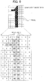
- the component image database 16 stores component image data of numerals 0, 1 to 9, symbols representing units, and the like.
- the display control unit 14 displays the color component image (as indicated by reference characters 61 to 63 in Fig. 3 ) in a prescribed coordinate position on the screen by using color component image data (as shown in Fig. 7 , which will be described later) constructed by component image data (as shown in Figs. 4 and 6 , which will be described later) and a color palette (as shown in Figs. 5 and 10(e) , which will be described later) converted to a user- designated tint.
- the image display unit 11 displays the present set temperature (a combination of numeral from 0 to 99 and a unit, for example) to the user.
- the color palette construction unit 15 constructs a color palette for implementing a tint desired by the user and stores it as a color palette database 17 in the storage device 18. After reading an existing color palette (as shown in Fig. 10(a) , which will be described later), the color palette construction unit 15 converts it to HSV values (as shown in Fig. 10(b) , which will be described later), changes the HSV values (that is, performs color tone change processing) (as shown in Fig. 10(d) , which will be described later) in accordance with the tint (as shown in Fig. 10(c) , which will be described later) input by the user operation, and generates a new color palette (as shown in Fig. 10(e) , which will be described later) by using the changed HSV values.
- Fig. 4 is a drawing showing an example of the component image database 16 in the first embodiment.
- the component image data include, for example, the image data of numerals from 0 to 9 and the image data of symbols representing Celsius and Fahrenheit.
- the color palette generated by the color palette construction unit 15 is stored.
- the color palette data included in the color palette database 17 are used by the display control unit 14.
- Fig. 5 is a conceptual diagram showing a configuration of a color palette stored in the color palette database 17 in the first embodiment.
- the color palette includes a plurality of entries (256 pieces in Fig. 5 ) (that is, color palette data), and each of the plurality of entries includes a color number (0 to 255 in Fig. 5 ) and an RGB value that is display color data, i.e., red (R), green (G) and blue (B) values.
- the color number is a numerical value from 0 to 255, and the color number is used to designate the color of a pixel of display component data.
- the number of color numbers is not limited to 256 and can be any other number.
- the display color data corresponding to the color number are 24-bit full-color data that indicate the color used when the pixel constituting the color component image displayed in the image display unit 11 is displayed.
- the 24-bit full-color data are data combining 8-bit R-color data, 8-bit G-color data, and 8-bit B-color data.
- the first entry in the color palette of a table structure is the entry of color number 0 and indicates the background color of the color component image.
- the entry of color number 1 and subsequent entries indicate the color of the numeral or character of the color component image, the color of shade, the color of the border, and the like and can be decided arbitrarily when the color component image is structured.
- Fig. 5 shows a color palette being data of a tint in a red range (including colors in a green range), and the tint of the color palette is changed by a user operation.
- Fig. 6 is a diagram showing an example of component image data (index values) of the component image database 16 shown in Fig. 5 .
- Fig. 7 is a diagram showing an example of color component image data (RGB values) generated based on the component image data (index values) in Fig. 6 and the color palette in Fig. 4 .
- the color (RGB value, that is, Pix0 to Pix255 in Fig. 7 ) of the color component image shown in Fig. 7 is determined by combining the index value (corresponding to the color number) indicated as each pixel of the component image shown in Fig. 6 and the entry of the display color corresponding to the color number included in the color palette shown in Fig. 5 .
- index value 0 of a pixel in the component image data shown in Fig. 6 is replaced by RGB (0, 0, 0) that is the display color data corresponding to color number 0 in the color palette shown in Fig. 5
- index value k (k 0, 1, ..., 255) of a pixel in the component image data shown in Fig.
- RGB rk, gk, bk
- the component image data (index value) do not include the display color data as shown in Fig. 6 , but the component image data in Fig. 6 is combined with the display color data obtained from the color palette in Fig. 5 and therefore the component image data including display color data as shown in Fig. 7 , that is, color component image data (RGB value) is obtained.
- Fig. 8 is a schematic drawing showing a color information setting screen of the image display unit 11 of the facility equipment management apparatus 10 in the first embodiment.
- the color information setting screen in Fig. 8 includes an indicator 41, which indicates the color tone corresponding to a present hue value, a Left Move button 42, a Right Move button 43, an OK button 44, a Cancel button 45, and an indicator guide 46, which indicates a settable range of the color tone.
- the indicator guide 46 indicates a guidable range corresponding to a changeable range of the hue value; the indicator 41 can move in a direction of length within the guide range; and a hue value can be specified by a position of the indicator 41 within the guide range.
- the indicator 41 and the indicator guide 46 are provided to help the user to intuitively know the color tone corresponding to the present hue value.
- the indicator 41 is displayed on the indicator guide 46 and displayed in the position corresponding to the present color tone.
- the Left Move button 42 is an operation button for moving the indicator 41 leftward on the indicator guide 46.
- the Right Move button 43 is an operation button for moving the indicator 41 rightward on the indicator guide 46.
- the hue value after the indicator is moved is a temporary value and is not a determined value until the OK button 44 is pressed.
- the OK button 44 is an operation button for setting the temporary hue value described above and making it the present hue value.
- the Cancel button 45 is an operation button for canceling the temporary hue value described above.
- characters such as Red, Blue, and Green indicate the color ranges of the image displayed on the image display unit 11. Accordingly, the user can change (set) the tint of the image displayed on the image display unit 11 according to a relative position of the indicator 41 rather than by inputting a numerical value indicating the hue value.
- Fig. 9 shows an operation from when the display control unit 14 constructs the color component screen data until when an image (e.g., a set temperature) is displayed on the image display unit 11 by using the constructed color component image data in the first embodiment.
- an image e.g., a set temperature
- step S1 the display control unit 14 reads component image data from the component image database 16, reads a color palette from the color palette database 17, and saves them in a temporary memory.
- the temporary memory can be a memory (not shown) in the display control unit 14 or another memory such as the storage device 18 shown in Fig. 1 .
- next step S2 the display control unit 14 reads display color data of the color numbers corresponding to the index values concerning pixels of the read component image data from the color palette and saves display image data obtained by replacing the index values to the display color data of its corresponding color numbers, that is, color component image data, in the temporary memory.
- next step S3 the display control unit 14 reads a display color of the entry of color number 0 (first entry) from read color palette, paints the whole surface of the image display unit 11 with the display color of the entry of color number 0, and thus the background color is set.
- next step S4 the display control unit 14 requests the communication unit 13 to acquire the present set temperature of the air conditioner 20.
- the communication unit 13 communicates with the air conditioner 20, acquires the present set temperature, and passes it to the display control unit 14. On this occasion, the communication unit 13 also passes information indicating whether the unit of the set temperature is Celsius or Fahrenheit.
- next step S5 the display control unit 14 displays the digit in the tens place (position denoted by reference character 61 in Fig. 3 ) of the set temperature. For example, if the digit in the tens place is 2, data corresponding to numeral "2" is read from the color component image data obtained by the conversion in step S2 and written in a specific coordinate of the image display unit 11.
- next step S6 the display control unit 14 displays the digit in the ones place (position denoted by reference character 62 in Fig. 3 ) of the set temperature. For example, if the digit in the ones place is 6, data corresponding to numeral "6" is read from the color component image data obtained by the conversion in step S2 and written in a specific coordinate of the image display unit 11. In this occasion, the digit in the ones place and the digit in the tens place displayed in step S5 do not overlap with each other.
- next step S7 the display control unit 14 displays the unit symbol (position denoted by reference character 63 in Fig. 3 ) of the set temperature. For example, if the unit is Celsius, data of "°C" is read from the image data obtained by the conversion in step S2 and written in a specific coordinate of the image display unit 11. On this occasion, the image data and the digit in the ones place displayed in step S6 do not overlap with each other.
- Figs. 10(a) to 10(e) are diagrams showing an operation of generating the color palette by the color palette construction unit 15 in the first embodiment.
- Fig. 11 is a flowchart showing the operation of generating the color palette by the color palette construction unit 15 in the first embodiment.
- step S11 the color palette construction unit 15 reads a present color palette from the color palette database 17 ( Fig. 10(a) ), and in next step S12, performs HSV conversion in relation to the display colors corresponding to the color numbers to convert all the colors to HSV values ( Fig. 10(b) ).
- the color palette construction unit 15 changes the HSV value of each color number obtained by the HSV conversion in step S12 on a basis of the user- designated color information (the position of the indicator 41 being the color information corresponding to a hue value) ( Figs. 10(c) and 10(d) ). Specifically, a new HSV value is calculated by changing the hue value by means of the position of the indicator 41 and not by changing the lightness and chroma besides.
- step S14 the color palette construction unit 15 performs RGB conversion, thereby converting the HSV values obtained in step S13 to RGB values ( Fig. 10(e) ).
- next step S15 the color palette construction unit 15 writes all the converted RGB values into the color palette database 17.
- the display control unit 14 constructs color component image data, and displays an image on the image display unit 11 by using the constructed color component image data. Therefore, the image is displayed with the tint according to the color tone designated (designated color information) by the user with the indicator 41.
- the color palette construction unit 15 changes the display color data of a color palette in accordance with the color tone (color information corresponding to hue values) designated on the color information setting screen by the user, and the display control unit 14 generates a display image using color component image data generated by combining component image data and color packet data. Accordingly, the size of image data stored in the apparatus is very small and thus the user can make the facility equipment management apparatus 10 display an image with a desired voluntary tint by a simple operation. For example, the user can provide a display screen that matches the room interior by making the color of the image displayed on the image display unit 11 be a color in the same range as the color of the wall surface 90.
- the color information setting screen displays the indicator 41 indicating the present color value (hue value) and the indicator guide 46 indicating the position in the whole color range, and the user can easily change the tint of the display screen to a color in a desired color range by moving the indicator 41.
- Described in the first embodiment above is an example of displaying the indicator 41 and the indicator guide 46 on the color information setting screen displayed by the image display unit 11 and changing the tint of the screen by the user moving the indicator 41 on the indicator guide 46.
- a facility equipment management apparatus differs from that of the first embodiment in that a hue value that is an HSV value is designated on the color information setting screen as a numerical value. Except for this point, the second embodiment is the same as the first embodiment. For this reason, the second embodiment will be described with reference to Figs. 1 to 5 also.
- Fig. 12 is a schematic diagram showing a color information setting screen of an image display unit 11 of the facility equipment management apparatus according to the second embodiment.
- the color information setting screen includes a hue value display box 51 which displays a hue value, an Add button 52, a Subtract button 53, an OK button 54, and a Cancel button 55 that are operation means.
- the hue value display box 51 displays the present hue value.
- the present hue value is displayed as an integer value (a hue of HSV value) from 0 to 360, for example.
- the Add button 52 is an operation button for increasing the hue value (adding 1) . If the Add button 52 is pressed when the hue value is 360, the hue value changes to 0. The hue value after the addition with the Add button 52 is a temporary value and is not a determined value until the OK button 54 is pressed.
- the Subtract button 53 is an operation button for decreasing the hue value (subtracting 1) . If the Subtract button 53 is pressed when the hue value is 0, the hue value changes to 360. The hue value after the subtraction with the Subtract button 53 is a temporary value and is not a determined value until the OK button 54 is pressed.
- the OK button 54 is an operation button for setting the temporary hue value described above as the present hue value.
- the Cancel button 55 is an operation button for canceling the temporary hue value described above.
- the facility equipment management apparatus displays the hue value as a numerical value and sets the hue value as the numerical value by means of addition or subtraction, so that the installer or other contractors who initialize the facility equipment can input a designated value accurately.
- Described in the first and second embodiments above is the configuration that the user sets a desired color tone through the color information setting screen displayed on the image display unit 11 by means of the position of the indicator 41 or a numerical value indicating the hue value.
- a facility equipment management apparatus differs from those in the first and second embodiments in that a hue value indicating the difference between hue values is designated as a numerical value on the color information setting screen. Except for this point, the third embodiment is the same as the first and second embodiments. For this reason, the third embodiment will be described with reference to Figs. 1 to 5 also.
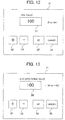
- Fig. 13 is a schematic diagram showing a color information setting screen of an image display unit 11 of the facility equipment management apparatus according to the third embodiment.
- the color information setting screen includes a hue difference value display box 56 that displays a hue difference value indicating a difference from the present hue value, an Add button 52, a Subtract button 53, an OK button 54, and a Cancel button 55.
- the hue value display box 51 is provided to display an amount of change from the present hue value.
- the hue difference value is displayed is an integer value in a range of +180 to -180.
- the Add button 52 is an operation button for increasing the hue difference value (adding 1). If the Add button 52 is pressed when the hue difference value is +180, the hue difference value changes to -180.
- the hue value after the addition with the Add button 52 is a temporary value and is not a determined value until the OK button 54 is pressed.
- the Subtract button 53 is an operation button for decreasing the hue difference value (subtracting 1). If the Subtract button 53 is pressed when the hue difference value is -180, the hue difference value changes to +180.
- the hue value after the subtraction with the Subtract button 53 is a temporary value and is not a determined value until the OK button 54 is pressed.
- the OK button 54 is an operation button for changing the hue value based on the hue difference value and setting it as the present hue value.
- the Cancel button 35 is an operation button for canceling the hue difference value described above.
- the facility equipment management apparatus displays a value of difference from the present hue value as a numerical value and sets the hue difference value as a numerical value by means of addition or subtraction, so that the user can easily change the tint of the display screen when adjusting the color during the operation.
- Described in the first to third embodiments above is the configuration that the user sets a desired color tone through the color information setting screen displayed on the image display unit 11 by means of the position of the indicator 41, the hue value, or the hue difference value. That is, in the first to third embodiments described above, the user who can change the color information on the color information setting screen is limited to a person who has some expertise in colors.
- a facility equipment management apparatus differs from those of the first to third embodiments in that the hue value is designated on a color bar (hue scale), which is a color sample, on the color information setting screen. Except for this point, the fourth embodiment is the same as the first to third embodiments. For this reason, the fourth embodiment will be described with reference to Figs. 1 to 5 also. In the fourth embodiment, the user who does not understand the meaning of technical terms such as the hue value and the hue difference value can easily make a setting on the color information setting screen.
- Fig. 14 is a schematic diagram showing a color information setting screen of an image display unit 11 of the facility equipment management apparatus according to the fourth embodiment.
- the color information setting screen includes an indicator 57 that indicates the present color tone, a Left Move button 52, a Right Move button 53, an OK button 54, a Cancel button 55, and an indicator guide 58 that indicates a settable color tone in the form of the color bar (hue scale).
- the color bar used as the indicator guide 58 a known hue scale in the HSV display color range can be used.
- the color bar can also be a hue ring.
- the indicator 57 is presented to help the user understand the present color tone intuitively.
- the indicator 57 is displayed on the indicator guide 58 and displayed in a position corresponding to the present color.
- the Left Move button 52, the Right Move button 53, the OK button 54, and the Cancel button 55 are the same as those in the first to third embodiments.
- the indicator guide 58 is a hue scale formed to change the color such as red, blue, and green continuously and the user can select a desired color intuitively.
- the guide is displayed like a color bar. Accordingly, the user can easily set a tint that the user wants to set as the tint of the display screen even if the user does not understand technical terms.
- Described in the first to third embodiments above is the configuration that the user sets a desired color tone through the color information setting screen displayed on the image display unit 11 by means of the position of the indicator 41, the hue value, or the hue difference value. That is, in the first to third embodiments described above, the user who can change the color information through the color information setting screen is limited to a person who has some expertise in colors.
- a facility equipment management apparatus differs from those in the first to fourth embodiments in that the user can determine through the information setting screen a tint the user wants to use while seeing a colored sample image of the screen that is actually displayed. Except for this point, the fifth embodiment is the same as the first to fourth embodiments. For this reason, the fifth embodiment will be described with reference to Figs. 1 to 5 also. In the case of the fifth embodiment, it is also possible for the user who does not understand the meaning of technical terms such as the hue value and the hue difference value to make the setting easily through the color information setting screen.
- Fig. 15 is a schematic diagram showing a color information setting screen of an image display unit 11 of the facility equipment management apparatus according to the fifth embodiment.
- the color information setting screen includes a sample image 59 showing a color tone of a present image, an Add button 52, a Subtract button 53, an OK button 54, and a Cancel button 55.
- the sample image 59 presents a sample of a tint of an image displayed in accordance with a present hue value to the user and helps the user understand the tint intuitively.
- the Add button 52, the Subtract button 53, the OK button 54, and the Cancel button 55 are the same as those in the second to fourth embodiments.
- the facility equipment management apparatus immediately reflects a tint according to the hue value in a sample image and presents such sample images successively to the user each time the Add button 52 or the Subtract button 53 is pressed, and the user can consequently set a desired tint while visually checking a final screen image. Therefore, the user can easily set a tint the user wants to set as the tint of the display screen even if the user does not understand technical terms.
- An example of application of the present invention is a control device, which is a facility equipment management apparatus that manages and remote-controls as air conditioner.
- the present invention can also be applied when the facility equipment to be managed is any other facility equipment such as lighting equipment and a security system.
Landscapes
- Engineering & Computer Science (AREA)
- Theoretical Computer Science (AREA)
- Physics & Mathematics (AREA)
- General Engineering & Computer Science (AREA)
- General Physics & Mathematics (AREA)
- Computer Hardware Design (AREA)
- Human Computer Interaction (AREA)
- Combustion & Propulsion (AREA)
- Mechanical Engineering (AREA)
- Chemical & Material Sciences (AREA)
- User Interface Of Digital Computer (AREA)
- Controls And Circuits For Display Device (AREA)
- Image Processing (AREA)
- Air Conditioning Control Device (AREA)
Abstract
Description
- The present invention relates to a facility equipment management apparatus for managing facility equipment, and specifically relates to a facility equipment management apparatus capable of setting the tint of a display image on an image display unit by a user operation.
- In recent years, in relation to a facility equipment management apparatus (a controller for an air conditioner, for example) set on a wall of a building, there has been a demand for including the facility equipment management apparatus with a function to change the color of a screen of an image display unit and thus making the color of the screen be a color in the same range as the color of the wall.
-
Patent Reference 1 suggests an air conditioner controller equipped with light emitting diodes (LED) of three colors to illuminate a screen of an image display unit. -
Patent Reference 2 suggests a control apparatus that includes a warm-color operation button and a cold-color operation button, adjusts color arrangement of the operation buttons, and thus makes a user feel a desired environment through visual perception. -
- Patent Reference 1: Japanese Patent Application Publication No.
2014-126319 - Patent Reference 2: Japanese Patent Application Publication No.
2016-031616 - However, the apparatus of
Patent Reference 1 does not have a function to change the color per se of the screen of the image display unit. - The apparatus of
patent literature 2 is capable of adjusting the colors of the operation buttons but takes no measures for appropriately setting a contrast between the screen background color and the text color. Therefore, it is difficult for the elderly, the visually-handicapped or the like to recognize characters. - The present invention has been made to solve the problems described above and has an object of providing a facility equipment management apparatus capable of changing a display image on an image display unit to have a desired tint while maintaining an appropriate contrast, by a user operation.
- A facility equipment management apparatus according to the present invention is an apparatus that performs communication with a facility equipment and manages an operation of the facility equipment; the facility equipment management apparatus includes an image display unit, a display control unit that makes the image display unit display an image, an operation input unit that receives a user operation, a color palette database that stores a color palette that includes a plurality of pieces of display color data, a color palette construction unit that changes the plurality of pieces of display color data of the color palette based on color information designated on the operation input unit, and a component image database that stores component image data which indicates a display component, wherein the display control unit constructs color component image data, which is the component image data including display color data based on the component image data and the color palette, and makes the image display unit display the image by using the color component image data.
- According to the present invention, an effect of changing a display image of an image display unit of a facility equipment management apparatus to a desired tint while maintaining an appropriate contrast can be obtained.
-
-
Fig. 1 is a functional block diagram schematically showing a configuration of a facility equipment management apparatus according to a first embodiment of the present invention. -
Fig. 2 is a diagram showing an example of a hardware configuration of the facility equipment management apparatus according to the first embodiment. -
Fig. 3 is an appearance diagram schematically showing the facility equipment management apparatus according to the first embodiment. -
Fig. 4 is a diagram showing an example of a component image database in the first embodiment. -
Fig. 5 is a diagram showing an example of a color palette database in the first embodiment. -
Fig. 6 is a diagram showing an example of component image data (index values) of the component image database shown inFig. 5 . -
Fig. 7 is a diagram showing an example of color component image data (RGB values) generated based on the component image data (index values) inFig. 6 and the color palette (RGB values) inFig. 4 . -
Fig. 8 is a schematic diagram showing a color information setting screen of the image display unit of the facility equipment management apparatus according to the first embodiment. -
Fig. 9 is a flowchart showing a display image generation operation by a display control unit in the first embodiment. -
Figs. 10(a) to 10(e) are diagrams showing a color palette generation operation by a color palette construction unit in the first embodiment. -
Fig. 11 is a flowchart showing the color palette generation operation by the color palette construction unit in the first embodiment. -
Fig. 12 is a schematic diagram showing a color information setting screen of an image display unit of a facility equipment management apparatus according to a second embodiment of the present invention. -
Fig. 13 is a schematic diagram showing a color information setting screen of an image display unit of a facility equipment management apparatus according to a third embodiment of the present invention. -
Fig. 14 is a schematic diagram showing a color information setting screen of an image display unit of a facility equipment management apparatus according to a fourth embodiment of the present invention. -
Fig. 15 is a schematic diagram showing a color information setting screen of an image display unit of a facility equipment management apparatus according to a fifth embodiment of the present invention. - Facility equipment management apparatuses of embodiments of the present invention will be described below with reference to attached drawings. The following embodiments are merely examples, and a variety of modifications are possible within the scope of the present invention.
-
Fig. 1 is a functional block diagram showing a schematic configuration of a facilityequipment management apparatus 10 according to a first embodiment. The facilityequipment management apparatus 10 is, for example, a remote control apparatus that is set on a wall of a building or the like and manages (controls) the operation and the state of an air conditioner as facility equipment. - As shown in
Fig. 1 , the facilityequipment management apparatus 10 includes animage display unit 11 that displays an image, anoperation input unit 12 that receives a user operation, acommunication unit 13 that performs communication with an external device, acomponent image database 16 that stores component image data, which are data of display components such as a numeral, a character, and a symbol, and acolor palette database 17 that stores a color palette that includes a plurality of pieces of display color data (color palette data). The facilityequipment management apparatus 10 also includes a colorpalette construction unit 15 that changes the color palette stored in thecolor palette database 17 based on color information (information corresponding to a hue value) designated by a user operation and adisplay control unit 14 that performs processing for making theimage display unit 11 display an image. - The
display control unit 14 has a function of a color component image data construction unit that constructs color component image data, which is component image data including display color data based on component image data read from thecomponent image database 16 and a color palette read from thecolor palette database 17. Thedisplay control unit 14 also has a function to generate display image data by using input display data and color component image data and to supply them to theimage display unit 11. - The
component image database 16 and thecolor palette database 17 are stored in astorage device 18 such as a semiconductor memory. Thestorage device 18 is, for example, a flash memory. Thecomponent image database 16 and thecolor palette database 17 can be stored in storage devices differing from each other. -
Fig. 2 is a diagram showing an example of a hardware (H/W) configuration of the facilityequipment management apparatus 10. The facilityequipment management apparatus 10 includes amemory 32 that stores a program as a software and a processor (CPU: central processing unit) 31 that is an information processing unit that executes the program stored in thememory 32. Theprocessor 31 and thememory 32 configure acontrol unit 30 that controls the operation of the facilityequipment management apparatus 10. By executing a program, theprocessor 31 can implement thedisplay control unit 14 and the colorpalette construction unit 15 shown inFig. 1 . -
Fig. 3 is an appearance diagram schematically showing the facilityequipment management apparatus 10. As shown inFig. 3 , the facilityequipment management apparatus 10 is set in a position visible to the user on awall surface 90 by securing means such as screws. The facilityequipment management apparatus 10 includes theimage display unit 11 such as a liquid crystal display and theoperation input unit 12 as a user operation unit. Theimage display unit 11 and theoperation input unit 12 can be a touch panel including an image display panel that displays an image and an operation panel that receives a user operation. Theimage display unit 11 is placed in such a manner that the user can see it, and theoperation input unit 12 is placed in such a manner that the user can operate it. The facilityequipment management apparatus 10 is connected through acommunication line 21 to theair conditioner 20 as equipment to be managed. For example, the user can recognize a set temperature of theair conditioner 20 by looking at the screen of theimage display unit 11 of the facilityequipment management apparatus 10. The user can also change an operation state and the set temperature of theair conditioner 20 by operating theoperation input unit 12 of the facilityequipment management apparatus 10. - The configuration of the facility
equipment management apparatus 10 will next be described more specifically. - The
image display unit 11 is, for example, a liquid crystal display utilizing color Thin Film Transistor (TFT) liquid crystal. Thedisplay control unit 14 can make theimage display unit 11 display a present set temperature of the air conditioner, which is the facility equipment. Thedisplay control unit 14 can make theimage display unit 11 display an image by using display components. The display components include numerals from 0 to 9 and unit symbols "°C", which denotes Celsius, and "°F", which denotes Fahrenheit. Theimage display unit 11 can display a color image. Thedisplay control unit 14 can make theimage display unit 11 display a color information setting screen through which the user inputs a desired tint. The tint input through the color information setting screen is information on a color desired by the user and, for example, information indicating a hue. Generally, the facilityequipment management apparatus 10 has prescribed a size (as 12 cm × 12 cm or 12 cm × 6 cm, for example) conforming to a standard, and the size of the screen of theimage display unit 11 is smaller than a size of the apparatus. - The
operation input unit 12 can be implemented by a resistive touch panel, for example. Theoperation input unit 12 and theimage display unit 11 are superposed, and theoperation input unit 12 and theimage display unit 11 form a touch panel that detects a touch input operation performed by the user with a finger. Theoperation input unit 12 detects a pressure received from the user's finger and acquires information corresponding to a position where the user touches as input content. When the user presses an operation button (operation means) as a display component displayed in a particular position of theimage display unit 11, theoperation input unit 12 performs processing for the request such as "OK", "Cancel", "Forward", "Backward", "Increase", "Decrease" etc. Theoperation input unit 12 also receives, through the color information setting screen, input instructions on the tint that the user desires made on theimage display unit 11. - The
communication unit 13 includes communication ICs (integrated circuits), for example. Thecommunication unit 13 performs communication with theair conditioner 20, which is the facility equipment to be managed. Generally, theair conditioner 20 includes an outdoor unit equipped with a compressor, a heat exchanger, a fan, and an electric motor, an indoor unit equipped with a heat exchanger, a fan, an electric motor, and a control circuit, and a refrigerant pipe for circulating a refrigerant between the outdoor unit and the indoor unit. Theair conditioner 20 stores the set temperature information as a target temperature of the operation. The facilityequipment management apparatus 10 can acquire the set temperature of theair conditioner 20 through thecommunication unit 13. It can also change the operation state and set temperature of theair conditioner 20 by sending a command from thecommunication unit 13. - The
display control unit 14 constructs color component image data that are used to make theimage display unit 11 display an image . The image displayed by theimage display unit 11 is formed by combining color component images based on color component image data. For example, thecomponent image database 16 stores component image data ofnumerals display control unit 14 displays the color component image (as indicated byreference characters 61 to 63 inFig. 3 ) in a prescribed coordinate position on the screen by using color component image data (as shown inFig. 7 , which will be described later) constructed by component image data (as shown inFigs. 4 and6 , which will be described later) and a color palette (as shown inFigs. 5 and10(e) , which will be described later) converted to a user- designated tint. In that way, theimage display unit 11 displays the present set temperature (a combination of numeral from 0 to 99 and a unit, for example) to the user. - The color
palette construction unit 15 constructs a color palette for implementing a tint desired by the user and stores it as acolor palette database 17 in thestorage device 18. After reading an existing color palette (as shown inFig. 10(a) , which will be described later), the colorpalette construction unit 15 converts it to HSV values (as shown inFig. 10(b) , which will be described later), changes the HSV values (that is, performs color tone change processing) (as shown inFig. 10(d) , which will be described later) in accordance with the tint (as shown inFig. 10(c) , which will be described later) input by the user operation, and generates a new color palette (as shown inFig. 10(e) , which will be described later) by using the changed HSV values. - In the
component image database 16, the component image data are saved.Fig. 4 is a drawing showing an example of thecomponent image database 16 in the first embodiment. The component image data include, for example, the image data of numerals from 0 to 9 and the image data of symbols representing Celsius and Fahrenheit. - In the
color palette database 17, the color palette generated by the colorpalette construction unit 15 is stored. The color palette data included in thecolor palette database 17 are used by thedisplay control unit 14. -
Fig. 5 is a conceptual diagram showing a configuration of a color palette stored in thecolor palette database 17 in the first embodiment. - The color palette includes a plurality of entries (256 pieces in
Fig. 5 ) (that is, color palette data), and each of the plurality of entries includes a color number (0 to 255 inFig. 5 ) and an RGB value that is display color data, i.e., red (R), green (G) and blue (B) values. In the example shown inFig. 5 , the color number is a numerical value from 0 to 255, and the color number is used to designate the color of a pixel of display component data. The number of color numbers is not limited to 256 and can be any other number. - The display color data corresponding to the color number are 24-bit full-color data that indicate the color used when the pixel constituting the color component image displayed in the
image display unit 11 is displayed. The 24-bit full-color data are data combining 8-bit R-color data, 8-bit G-color data, and 8-bit B-color data. - In
Fig. 5 , the first entry in the color palette of a table structure is the entry ofcolor number 0 and indicates the background color of the color component image. InFig. 5 , the entry ofcolor number 1 and subsequent entries indicate the color of the numeral or character of the color component image, the color of shade, the color of the border, and the like and can be decided arbitrarily when the color component image is structured.Fig. 5 shows a color palette being data of a tint in a red range (including colors in a green range), and the tint of the color palette is changed by a user operation. -
Fig. 6 is a diagram showing an example of component image data (index values) of thecomponent image database 16 shown inFig. 5 .Fig. 7 is a diagram showing an example of color component image data (RGB values) generated based on the component image data (index values) inFig. 6 and the color palette inFig. 4 . - The color (RGB value, that is, Pix0 to Pix255 in
Fig. 7 ) of the color component image shown inFig. 7 is determined by combining the index value (corresponding to the color number) indicated as each pixel of the component image shown inFig. 6 and the entry of the display color corresponding to the color number included in the color palette shown inFig. 5 . For example,index value 0 of a pixel in the component image data shown inFig. 6 is replaced by RGB (0, 0, 0) that is the display color data corresponding tocolor number 0 in the color palette shown inFig. 5 , and index value k (k = 0, 1, ..., 255) of a pixel in the component image data shown inFig. 6 is replaced by RGB (rk, gk, bk) that is the display color data corresponding to color number k in the color palette shown inFig. 5 . That is, if the display color data of the color palette are in the red range, the color component image data becomes the data of the red range; if the display color data of the color palette are in the blue range, the color component image data becomes the data of the blue range; and if the display color data of the color palette are in the green range, the color component image data becomes the data of the green range. - In summary, the component image data (index value) do not include the display color data as shown in
Fig. 6 , but the component image data inFig. 6 is combined with the display color data obtained from the color palette inFig. 5 and therefore the component image data including display color data as shown inFig. 7 , that is, color component image data (RGB value) is obtained. -
Fig. 8 is a schematic drawing showing a color information setting screen of theimage display unit 11 of the facilityequipment management apparatus 10 in the first embodiment. The color information setting screen inFig. 8 includes anindicator 41, which indicates the color tone corresponding to a present hue value, aLeft Move button 42, aRight Move button 43, anOK button 44, a Cancelbutton 45, and anindicator guide 46, which indicates a settable range of the color tone. Theindicator guide 46 indicates a guidable range corresponding to a changeable range of the hue value; theindicator 41 can move in a direction of length within the guide range; and a hue value can be specified by a position of theindicator 41 within the guide range. - The
indicator 41 and theindicator guide 46 are provided to help the user to intuitively know the color tone corresponding to the present hue value. Theindicator 41 is displayed on theindicator guide 46 and displayed in the position corresponding to the present color tone. - The
Left Move button 42 is an operation button for moving theindicator 41 leftward on theindicator guide 46. TheRight Move button 43 is an operation button for moving theindicator 41 rightward on theindicator guide 46. The hue value after the indicator is moved is a temporary value and is not a determined value until theOK button 44 is pressed. - The
OK button 44 is an operation button for setting the temporary hue value described above and making it the present hue value. The Cancelbutton 45 is an operation button for canceling the temporary hue value described above. - On the
indicator guide 46, characters such as Red, Blue, and Green indicate the color ranges of the image displayed on theimage display unit 11. Accordingly, the user can change (set) the tint of the image displayed on theimage display unit 11 according to a relative position of theindicator 41 rather than by inputting a numerical value indicating the hue value. -
Fig. 9 shows an operation from when thedisplay control unit 14 constructs the color component screen data until when an image (e.g., a set temperature) is displayed on theimage display unit 11 by using the constructed color component image data in the first embodiment. - In step S1, the
display control unit 14 reads component image data from thecomponent image database 16, reads a color palette from thecolor palette database 17, and saves them in a temporary memory. The temporary memory can be a memory (not shown) in thedisplay control unit 14 or another memory such as thestorage device 18 shown inFig. 1 . - In next step S2, the
display control unit 14 reads display color data of the color numbers corresponding to the index values concerning pixels of the read component image data from the color palette and saves display image data obtained by replacing the index values to the display color data of its corresponding color numbers, that is, color component image data, in the temporary memory. - In next step S3, the
display control unit 14 reads a display color of the entry of color number 0 (first entry) from read color palette, paints the whole surface of theimage display unit 11 with the display color of the entry ofcolor number 0, and thus the background color is set. - In next step S4, the
display control unit 14 requests thecommunication unit 13 to acquire the present set temperature of theair conditioner 20. Thecommunication unit 13 communicates with theair conditioner 20, acquires the present set temperature, and passes it to thedisplay control unit 14. On this occasion, thecommunication unit 13 also passes information indicating whether the unit of the set temperature is Celsius or Fahrenheit. - In next step S5, the
display control unit 14 displays the digit in the tens place (position denoted byreference character 61 inFig. 3 ) of the set temperature. For example, if the digit in the tens place is 2, data corresponding to numeral "2" is read from the color component image data obtained by the conversion in step S2 and written in a specific coordinate of theimage display unit 11. - In next step S6, the
display control unit 14 displays the digit in the ones place (position denoted byreference character 62 inFig. 3 ) of the set temperature. For example, if the digit in the ones place is 6, data corresponding to numeral "6" is read from the color component image data obtained by the conversion in step S2 and written in a specific coordinate of theimage display unit 11. In this occasion, the digit in the ones place and the digit in the tens place displayed in step S5 do not overlap with each other. - In next step S7, the
display control unit 14 displays the unit symbol (position denoted byreference character 63 inFig. 3 ) of the set temperature. For example, if the unit is Celsius, data of "°C" is read from the image data obtained by the conversion in step S2 and written in a specific coordinate of theimage display unit 11. On this occasion, the image data and the digit in the ones place displayed in step S6 do not overlap with each other. - Next, the construction (generation) of a new color palette on the basis of a user-designated color tone (color information indicating a hue value and the position of the
indicator 41 in the first embodiment) will be described. This construction of color palette is performed prior to the processing of step S1 inFig. 9 . -
Figs. 10(a) to 10(e) are diagrams showing an operation of generating the color palette by the colorpalette construction unit 15 in the first embodiment.Fig. 11 is a flowchart showing the operation of generating the color palette by the colorpalette construction unit 15 in the first embodiment. - In step S11, the color
palette construction unit 15 reads a present color palette from the color palette database 17 (Fig. 10(a) ), and in next step S12, performs HSV conversion in relation to the display colors corresponding to the color numbers to convert all the colors to HSV values (Fig. 10(b) ). - In next step S13, the color
palette construction unit 15 changes the HSV value of each color number obtained by the HSV conversion in step S12 on a basis of the user- designated color information (the position of theindicator 41 being the color information corresponding to a hue value) (Figs. 10(c) and 10(d) ). Specifically, a new HSV value is calculated by changing the hue value by means of the position of theindicator 41 and not by changing the lightness and chroma besides. - In next step S14, the color
palette construction unit 15 performs RGB conversion, thereby converting the HSV values obtained in step S13 to RGB values (Fig. 10(e) ). - In next step S15, the color
palette construction unit 15 writes all the converted RGB values into thecolor palette database 17. - Referring to the new color palette, the
display control unit 14 constructs color component image data, and displays an image on theimage display unit 11 by using the constructed color component image data. Therefore, the image is displayed with the tint according to the color tone designated (designated color information) by the user with theindicator 41. - As described above, in the facility
equipment management apparatus 10 according to the first embodiment, for theimage display unit 11 that can display color images, the colorpalette construction unit 15 changes the display color data of a color palette in accordance with the color tone (color information corresponding to hue values) designated on the color information setting screen by the user, and thedisplay control unit 14 generates a display image using color component image data generated by combining component image data and color packet data. Accordingly, the size of image data stored in the apparatus is very small and thus the user can make the facilityequipment management apparatus 10 display an image with a desired voluntary tint by a simple operation. For example, the user can provide a display screen that matches the room interior by making the color of the image displayed on theimage display unit 11 be a color in the same range as the color of thewall surface 90. - Moreover, as described above, the color information setting screen displays the
indicator 41 indicating the present color value (hue value) and theindicator guide 46 indicating the position in the whole color range, and the user can easily change the tint of the display screen to a color in a desired color range by moving theindicator 41. - Described in the first embodiment above is an example of displaying the
indicator 41 and theindicator guide 46 on the color information setting screen displayed by theimage display unit 11 and changing the tint of the screen by the user moving theindicator 41 on theindicator guide 46. - A facility equipment management apparatus according to a second embodiment differs from that of the first embodiment in that a hue value that is an HSV value is designated on the color information setting screen as a numerical value. Except for this point, the second embodiment is the same as the first embodiment. For this reason, the second embodiment will be described with reference to
Figs. 1 to 5 also. -
Fig. 12 is a schematic diagram showing a color information setting screen of animage display unit 11 of the facility equipment management apparatus according to the second embodiment. The color information setting screen includes a huevalue display box 51 which displays a hue value, anAdd button 52, a Subtractbutton 53, anOK button 54, and a Cancelbutton 55 that are operation means. - The hue
value display box 51 displays the present hue value. The present hue value is displayed as an integer value (a hue of HSV value) from 0 to 360, for example. - The
Add button 52 is an operation button for increasing the hue value (adding 1) . If theAdd button 52 is pressed when the hue value is 360, the hue value changes to 0. The hue value after the addition with theAdd button 52 is a temporary value and is not a determined value until theOK button 54 is pressed. - The Subtract
button 53 is an operation button for decreasing the hue value (subtracting 1) . If the Subtractbutton 53 is pressed when the hue value is 0, the hue value changes to 360. The hue value after the subtraction with the Subtractbutton 53 is a temporary value and is not a determined value until theOK button 54 is pressed. - The
OK button 54 is an operation button for setting the temporary hue value described above as the present hue value. The Cancelbutton 55 is an operation button for canceling the temporary hue value described above. - As described above, the facility equipment management apparatus according to the second embodiment displays the hue value as a numerical value and sets the hue value as the numerical value by means of addition or subtraction, so that the installer or other contractors who initialize the facility equipment can input a designated value accurately.
- Described in the first and second embodiments above is the configuration that the user sets a desired color tone through the color information setting screen displayed on the
image display unit 11 by means of the position of theindicator 41 or a numerical value indicating the hue value. - A facility equipment management apparatus according to a third embodiment differs from those in the first and second embodiments in that a hue value indicating the difference between hue values is designated as a numerical value on the color information setting screen. Except for this point, the third embodiment is the same as the first and second embodiments. For this reason, the third embodiment will be described with reference to
Figs. 1 to 5 also. -
Fig. 13 is a schematic diagram showing a color information setting screen of animage display unit 11 of the facility equipment management apparatus according to the third embodiment. The color information setting screen includes a hue differencevalue display box 56 that displays a hue difference value indicating a difference from the present hue value, anAdd button 52, a Subtractbutton 53, anOK button 54, and a Cancelbutton 55. - The hue
value display box 51 is provided to display an amount of change from the present hue value. The hue difference value is displayed is an integer value in a range of +180 to -180. - The
Add button 52 is an operation button for increasing the hue difference value (adding 1). If theAdd button 52 is pressed when the hue difference value is +180, the hue difference value changes to -180. The hue value after the addition with theAdd button 52 is a temporary value and is not a determined value until theOK button 54 is pressed. - The Subtract
button 53 is an operation button for decreasing the hue difference value (subtracting 1). If the Subtractbutton 53 is pressed when the hue difference value is -180, the hue difference value changes to +180. The hue value after the subtraction with the Subtractbutton 53 is a temporary value and is not a determined value until theOK button 54 is pressed. - The
OK button 54 is an operation button for changing the hue value based on the hue difference value and setting it as the present hue value. The new hue value is calculated as the following expression:
- The Cancel button 35 is an operation button for canceling the hue difference value described above.
- As described above, the facility equipment management apparatus according to the third embodiment displays a value of difference from the present hue value as a numerical value and sets the hue difference value as a numerical value by means of addition or subtraction, so that the user can easily change the tint of the display screen when adjusting the color during the operation.
- Described in the first to third embodiments above is the configuration that the user sets a desired color tone through the color information setting screen displayed on the
image display unit 11 by means of the position of theindicator 41, the hue value, or the hue difference value. That is, in the first to third embodiments described above, the user who can change the color information on the color information setting screen is limited to a person who has some expertise in colors. - A facility equipment management apparatus according to a fourth embodiment differs from those of the first to third embodiments in that the hue value is designated on a color bar (hue scale), which is a color sample, on the color information setting screen. Except for this point, the fourth embodiment is the same as the first to third embodiments. For this reason, the fourth embodiment will be described with reference to
Figs. 1 to 5 also. In the fourth embodiment, the user who does not understand the meaning of technical terms such as the hue value and the hue difference value can easily make a setting on the color information setting screen. -
Fig. 14 is a schematic diagram showing a color information setting screen of animage display unit 11 of the facility equipment management apparatus according to the fourth embodiment. The color information setting screen includes anindicator 57 that indicates the present color tone, aLeft Move button 52, aRight Move button 53, anOK button 54, a Cancelbutton 55, and anindicator guide 58 that indicates a settable color tone in the form of the color bar (hue scale). As the color bar used as theindicator guide 58, a known hue scale in the HSV display color range can be used. The color bar can also be a hue ring. - The
indicator 57 is presented to help the user understand the present color tone intuitively. Theindicator 57 is displayed on theindicator guide 58 and displayed in a position corresponding to the present color. - The
Left Move button 52, theRight Move button 53, theOK button 54, and the Cancelbutton 55 are the same as those in the first to third embodiments. - As described above, in the facility equipment management apparatus according to the fourth embodiment, the
indicator guide 58 is a hue scale formed to change the color such as red, blue, and green continuously and the user can select a desired color intuitively. Specifically, the guide is displayed like a color bar. Accordingly, the user can easily set a tint that the user wants to set as the tint of the display screen even if the user does not understand technical terms. - Described in the first to third embodiments above is the configuration that the user sets a desired color tone through the color information setting screen displayed on the
image display unit 11 by means of the position of theindicator 41, the hue value, or the hue difference value. That is, in the first to third embodiments described above, the user who can change the color information through the color information setting screen is limited to a person who has some expertise in colors. - A facility equipment management apparatus according to a fifth embodiment differs from those in the first to fourth embodiments in that the user can determine through the information setting screen a tint the user wants to use while seeing a colored sample image of the screen that is actually displayed. Except for this point, the fifth embodiment is the same as the first to fourth embodiments. For this reason, the fifth embodiment will be described with reference to
Figs. 1 to 5 also. In the case of the fifth embodiment, it is also possible for the user who does not understand the meaning of technical terms such as the hue value and the hue difference value to make the setting easily through the color information setting screen. -
Fig. 15 is a schematic diagram showing a color information setting screen of animage display unit 11 of the facility equipment management apparatus according to the fifth embodiment. The color information setting screen includes asample image 59 showing a color tone of a present image, anAdd button 52, a Subtractbutton 53, anOK button 54, and a Cancelbutton 55. Thesample image 59 presents a sample of a tint of an image displayed in accordance with a present hue value to the user and helps the user understand the tint intuitively. - The
Add button 52, the Subtractbutton 53, theOK button 54, and the Cancelbutton 55 are the same as those in the second to fourth embodiments. - As described above, the facility equipment management apparatus according to the fifth embodiment immediately reflects a tint according to the hue value in a sample image and presents such sample images successively to the user each time the
Add button 52 or the Subtractbutton 53 is pressed, and the user can consequently set a desired tint while visually checking a final screen image. Therefore, the user can easily set a tint the user wants to set as the tint of the display screen even if the user does not understand technical terms. - An example of application of the present invention is a control device, which is a facility equipment management apparatus that manages and remote-controls as air conditioner. The present invention can also be applied when the facility equipment to be managed is any other facility equipment such as lighting equipment and a security system.
- 10 Facility equipment management apparatus, 11 Image display unit, 12 Operation input unit, 13 Communication unit, 14 Display control unit, 15 Color palette construction unit, 16 Component image database, 17 Color palette database, 18 Storage device, 31 Processor, 32 Memory, 20 Air conditioner, 90 Wall surface.
Claims (7)
- A facility equipment management apparatus that performs communication with a facility equipment and manages an operation of the facility equipment, the facility equipment management apparatus comprising:an image display unit;a display control unit that makes the image display unit display an image;an operation input unit that receives a user operation;a color palette database that stores a color palette that includes a plurality of pieces of display color data;a color palette construction unit that changes the plurality of pieces of display color data of the color palette based on color information designated on the operation input unit; anda component image database that stores component image data which indicates a display component;wherein the display control unit constructs color component image data, which is the component image data including display color data based on the component image data and the color palette, and makes the image display unit display the image by using the color component image data.
- The facility equipment management apparatus of claim 1, wherein the color information designated on the operation input unit is information corresponding to a hue value.
- The facility equipment management apparatus of claim 2, wherein the display control unit makes the image display unit display a color information setting screen, and
the color information setting screen includes:an indicator that indicates the hue value;an indicator guide that has a guide range corresponding to a range in which the hue value can be changed and specifies the hue value based on a position of the indicator within the guide range, the indicator being movable in a direction of length of the guide range, andan operation means that changes the position of the indicator. - The facility equipment management apparatus of claim 2, wherein the display control unit makes the image display unit display a color information setting screen, and
the color information setting screen includes:a display area in which an absolute value of a present value of the hue value is displayed; andan operation means that increases or decreases the hue value. - The facility equipment management apparatus of claim 2, wherein the display control unit makes the image display unit display a color information setting screen, and the color information setting screen includes:a display area in which a hue difference value, which is a difference between a present value of the hue value and a changed value of the hue value is displayed; andan operation means that increases or decreases the hue difference value.
- The facility equipment management apparatus of claim 2, wherein the display control unit makes the image display unit display a color information setting screen, and the color information setting screen includes:an indicator that indicates the hue value;an indicator guide that has a guide range corresponding to a range in which the hue value can be changed and is a hue scale that specifies the hue value based on a position of the indicator within the guide range, the indicator being movable in a direction of length of the guide range, andan operation means that changes the position of the indicator.
- The facility equipment management apparatus of claim 2, wherein the display control unit makes the image display unit display a color information setting screen, and the color information setting screen includes:a sample image display area in which a color sample image based on a changed value of the hue value is displayed; andan operation means that increases or decreases the hue value.
Applications Claiming Priority (1)
| Application Number | Priority Date | Filing Date | Title |
|---|---|---|---|
| PCT/JP2017/011690 WO2018173188A1 (en) | 2017-03-23 | 2017-03-23 | Equipment apparatus management device |
Publications (3)
| Publication Number | Publication Date |
|---|---|
| EP3604949A1 true EP3604949A1 (en) | 2020-02-05 |
| EP3604949A4 EP3604949A4 (en) | 2020-04-08 |
| EP3604949B1 EP3604949B1 (en) | 2025-01-22 |
Family
ID=63586287
Family Applications (1)
| Application Number | Title | Priority Date | Filing Date |
|---|---|---|---|
| EP17901624.1A Active EP3604949B1 (en) | 2017-03-23 | 2017-03-23 | Facility equipment management apparatus |
Country Status (5)
| Country | Link |
|---|---|
| US (1) | US10867581B2 (en) |
| EP (1) | EP3604949B1 (en) |
| JP (1) | JP6700477B2 (en) |
| CN (1) | CN110419032B (en) |
| WO (1) | WO2018173188A1 (en) |
Families Citing this family (3)
| Publication number | Priority date | Publication date | Assignee | Title |
|---|---|---|---|---|
| JP7465660B2 (en) * | 2020-01-15 | 2024-04-11 | シャープ株式会社 | Information processing device and information processing system |
| TWI805286B (en) * | 2022-03-24 | 2023-06-11 | 香港商冠捷投資有限公司 | Display effect adjustment method and display device |
| WO2026069135A1 (en) * | 2024-09-27 | 2026-04-02 | Copeland Controls Srl | User interface displays for refrigeration and/or hvacr applications |
Family Cites Families (16)
| Publication number | Priority date | Publication date | Assignee | Title |
|---|---|---|---|---|
| AT316067B (en) * | 1967-10-11 | 1974-06-25 | Ing Paul Odelga Dipl | Air distribution system |
| JPH02128299A (en) * | 1988-11-09 | 1990-05-16 | Hitachi Ltd | process monitoring system |
| JP2001195051A (en) * | 2000-01-12 | 2001-07-19 | Konami Co Ltd | Data generating device for image display and recording medium |
| US20080204470A1 (en) * | 2007-02-27 | 2008-08-28 | Kabushiki Kaisha Toshiba | Display apparatus, image forming apparatus and display method |
| JP4999598B2 (en) * | 2007-08-10 | 2012-08-15 | キヤノン株式会社 | Image processing apparatus and control method thereof |
| US20100274476A1 (en) | 2007-11-20 | 2010-10-28 | Aisin AW Co.Ltd | Navigation device |
| JP2010154365A (en) * | 2008-12-25 | 2010-07-08 | Olympus Imaging Corp | Color correction device, camera, color correction method, and color correction program |
| WO2011007623A1 (en) * | 2009-07-17 | 2011-01-20 | 三菱電機株式会社 | Facility operation display device, air-conditioning system, and program |
| JP5640550B2 (en) * | 2010-08-19 | 2014-12-17 | セイコーエプソン株式会社 | Color conversion instruction apparatus and program |
| JP5522491B2 (en) * | 2011-12-13 | 2014-06-18 | 横河電機株式会社 | Alarm display device and alarm display method |
| KR101435904B1 (en) * | 2012-11-15 | 2014-09-02 | 구자호 | A device to install double-layer walls and double- layer chimneys connected to the walls for circulation of inside and outside air and related facilities. |
| JP6091208B2 (en) | 2012-12-27 | 2017-03-08 | 三菱電機株式会社 | Air conditioner controller and air conditioning system |
| US10972742B2 (en) * | 2013-12-19 | 2021-04-06 | Canon Kabushiki Kaisha | Encoding process using a palette mode |
| JP2016031616A (en) | 2014-07-28 | 2016-03-07 | 株式会社Nttファシリティーズ | Control system, terminal device, control server, control method and program |
| JP6381789B2 (en) * | 2015-04-15 | 2018-08-29 | 三菱電機株式会社 | Display control device and control terminal |
| CN114108873B (en) * | 2021-11-30 | 2023-01-06 | 刘向峰 | Energy-saving air interlayer capable of exhausting and foaming |
-
2017
- 2017-03-23 WO PCT/JP2017/011690 patent/WO2018173188A1/en not_active Ceased
- 2017-03-23 CN CN201780085963.8A patent/CN110419032B/en not_active Expired - Fee Related
- 2017-03-23 JP JP2019506824A patent/JP6700477B2/en not_active Expired - Fee Related
- 2017-03-23 US US16/477,544 patent/US10867581B2/en active Active
- 2017-03-23 EP EP17901624.1A patent/EP3604949B1/en active Active
Also Published As
| Publication number | Publication date |
|---|---|
| JP6700477B2 (en) | 2020-05-27 |
| WO2018173188A1 (en) | 2018-09-27 |
| CN110419032A (en) | 2019-11-05 |
| US10867581B2 (en) | 2020-12-15 |
| CN110419032B (en) | 2023-02-28 |
| JPWO2018173188A1 (en) | 2019-11-07 |
| EP3604949B1 (en) | 2025-01-22 |
| US20200020300A1 (en) | 2020-01-16 |
| EP3604949A4 (en) | 2020-04-08 |
Similar Documents
| Publication | Publication Date | Title |
|---|---|---|
| CN101714349B (en) | Color adjustment system for display device and printed material | |
| US11176865B2 (en) | Electronic device, display apparatus, and control method thereof | |
| JP6199903B2 (en) | Remote control of light source | |
| US20180342224A1 (en) | Electronic device, and display panel device correction method and system thereof | |
| CN104157261B (en) | Display mode adjustment method of display device and display mode adjustment module thereof | |
| EP3604949B1 (en) | Facility equipment management apparatus | |
| CN103428404A (en) | Color processing apparatus and color processing method | |
| US10853020B2 (en) | Image sharing method, information processing device, and information processing system | |
| CN102800277A (en) | Method for adjusting color and luminance of display equipment and display device | |
| EP2837922A2 (en) | Color calibration device, color calibration method thereof, display apparatus and display system having the same | |
| CN111724324A (en) | A color gamut conversion method, device, electronic device and storage medium | |
| CN101720046A (en) | Method for reproducing colors from display to projector by utilizing human eyes | |
| US10354614B2 (en) | Technique for color management for a set of display devices | |
| TWI693591B (en) | Method for adjusting uniformity of image color tones and system thereof | |
| JP5496382B2 (en) | Display device color adjustment system | |
| JP2010217133A (en) | Adaptation point prediction device, perception color prediction device, adaptation point prediction method and perception color prediction method | |
| CN111103992B (en) | Display device, display method and display system | |
| JP5484613B2 (en) | Display device color adjustment system | |
| JP5058532B2 (en) | Image display system and image display method | |
| CN117043844A (en) | Image display system, image display method, image display program and image display device | |
| CN112484847A (en) | Illuminance measuring device and illuminance measuring method | |
| WO2022086537A1 (en) | Ambient lighting creation based on a target color temperature range | |
| KR20160066969A (en) | Method for displaying graphic user infterface screen and an electronic device thereof | |
| JP2023177061A (en) | Image processing device and image processing method | |
| Yum et al. | White constancy method for mobile displays |
Legal Events
| Date | Code | Title | Description |
|---|---|---|---|
| STAA | Information on the status of an ep patent application or granted ep patent |
Free format text: STATUS: THE INTERNATIONAL PUBLICATION HAS BEEN MADE |
|
| PUAI | Public reference made under article 153(3) epc to a published international application that has entered the european phase |
Free format text: ORIGINAL CODE: 0009012 |
|
| STAA | Information on the status of an ep patent application or granted ep patent |
Free format text: STATUS: REQUEST FOR EXAMINATION WAS MADE |
|
| 17P | Request for examination filed |
Effective date: 20190909 |
|
| AK | Designated contracting states |
Kind code of ref document: A1 Designated state(s): AL AT BE BG CH CY CZ DE DK EE ES FI FR GB GR HR HU IE IS IT LI LT LU LV MC MK MT NL NO PL PT RO RS SE SI SK SM TR |
|
| AX | Request for extension of the european patent |
Extension state: BA ME |
|
| A4 | Supplementary search report drawn up and despatched |
Effective date: 20200305 |
|
| RIC1 | Information provided on ipc code assigned before grant |
Ipc: F24F 11/52 20180101ALI20200228BHEP Ipc: G09G 5/06 20060101ALI20200228BHEP Ipc: F24F 11/30 20180101AFI20200228BHEP |
|
| DAV | Request for validation of the european patent (deleted) | ||
| DAX | Request for extension of the european patent (deleted) | ||
| STAA | Information on the status of an ep patent application or granted ep patent |
Free format text: STATUS: EXAMINATION IS IN PROGRESS |
|
| 17Q | First examination report despatched |
Effective date: 20210112 |
|
| GRAP | Despatch of communication of intention to grant a patent |
Free format text: ORIGINAL CODE: EPIDOSNIGR1 |
|
| STAA | Information on the status of an ep patent application or granted ep patent |
Free format text: STATUS: GRANT OF PATENT IS INTENDED |
|
| INTG | Intention to grant announced |
Effective date: 20240822 |
|
| RIN1 | Information on inventor provided before grant (corrected) |
Inventor name: GYOTA ,TOMOAKI Inventor name: KATSUKURA, MAKOTO |
|
| GRAS | Grant fee paid |
Free format text: ORIGINAL CODE: EPIDOSNIGR3 |
|
| GRAA | (expected) grant |
Free format text: ORIGINAL CODE: 0009210 |
|
| STAA | Information on the status of an ep patent application or granted ep patent |
Free format text: STATUS: THE PATENT HAS BEEN GRANTED |
|
| AK | Designated contracting states |
Kind code of ref document: B1 Designated state(s): AL AT BE BG CH CY CZ DE DK EE ES FI FR GB GR HR HU IE IS IT LI LT LU LV MC MK MT NL NO PL PT RO RS SE SI SK SM TR |
|
| REG | Reference to a national code |
Ref country code: GB Ref legal event code: FG4D |
|
| REG | Reference to a national code |
Ref country code: CH Ref legal event code: EP |
|
| REG | Reference to a national code |
Ref country code: IE Ref legal event code: FG4D |
|
| REG | Reference to a national code |
Ref country code: DE Ref legal event code: R096 Ref document number: 602017087493 Country of ref document: DE |
|
| REG | Reference to a national code |
Ref country code: NL Ref legal event code: MP Effective date: 20250122 |
|
| PG25 | Lapsed in a contracting state [announced via postgrant information from national office to epo] |
Ref country code: NL Free format text: LAPSE BECAUSE OF FAILURE TO SUBMIT A TRANSLATION OF THE DESCRIPTION OR TO PAY THE FEE WITHIN THE PRESCRIBED TIME-LIMIT Effective date: 20250122 |
|
| PG25 | Lapsed in a contracting state [announced via postgrant information from national office to epo] |
Ref country code: RS Free format text: LAPSE BECAUSE OF FAILURE TO SUBMIT A TRANSLATION OF THE DESCRIPTION OR TO PAY THE FEE WITHIN THE PRESCRIBED TIME-LIMIT Effective date: 20250422 |
|
| PG25 | Lapsed in a contracting state [announced via postgrant information from national office to epo] |
Ref country code: FI Free format text: LAPSE BECAUSE OF FAILURE TO SUBMIT A TRANSLATION OF THE DESCRIPTION OR TO PAY THE FEE WITHIN THE PRESCRIBED TIME-LIMIT Effective date: 20250122 |
|
| PG25 | Lapsed in a contracting state [announced via postgrant information from national office to epo] |
Ref country code: PL Free format text: LAPSE BECAUSE OF FAILURE TO SUBMIT A TRANSLATION OF THE DESCRIPTION OR TO PAY THE FEE WITHIN THE PRESCRIBED TIME-LIMIT Effective date: 20250122 |
|
| PG25 | Lapsed in a contracting state [announced via postgrant information from national office to epo] |
Ref country code: ES Free format text: LAPSE BECAUSE OF FAILURE TO SUBMIT A TRANSLATION OF THE DESCRIPTION OR TO PAY THE FEE WITHIN THE PRESCRIBED TIME-LIMIT Effective date: 20250122 |
|
| REG | Reference to a national code |
Ref country code: LT Ref legal event code: MG9D |
|
| PG25 | Lapsed in a contracting state [announced via postgrant information from national office to epo] |
Ref country code: IS Free format text: LAPSE BECAUSE OF FAILURE TO SUBMIT A TRANSLATION OF THE DESCRIPTION OR TO PAY THE FEE WITHIN THE PRESCRIBED TIME-LIMIT Effective date: 20250522 Ref country code: NO Free format text: LAPSE BECAUSE OF FAILURE TO SUBMIT A TRANSLATION OF THE DESCRIPTION OR TO PAY THE FEE WITHIN THE PRESCRIBED TIME-LIMIT Effective date: 20250422 |
|
| REG | Reference to a national code |
Ref country code: AT Ref legal event code: MK05 Ref document number: 1761729 Country of ref document: AT Kind code of ref document: T Effective date: 20250122 |
|
| PG25 | Lapsed in a contracting state [announced via postgrant information from national office to epo] |
Ref country code: HR Free format text: LAPSE BECAUSE OF FAILURE TO SUBMIT A TRANSLATION OF THE DESCRIPTION OR TO PAY THE FEE WITHIN THE PRESCRIBED TIME-LIMIT Effective date: 20250122 |
|
| PG25 | Lapsed in a contracting state [announced via postgrant information from national office to epo] |
Ref country code: LV Free format text: LAPSE BECAUSE OF FAILURE TO SUBMIT A TRANSLATION OF THE DESCRIPTION OR TO PAY THE FEE WITHIN THE PRESCRIBED TIME-LIMIT Effective date: 20250122 Ref country code: PT Free format text: LAPSE BECAUSE OF FAILURE TO SUBMIT A TRANSLATION OF THE DESCRIPTION OR TO PAY THE FEE WITHIN THE PRESCRIBED TIME-LIMIT Effective date: 20250522 |
|
| PG25 | Lapsed in a contracting state [announced via postgrant information from national office to epo] |
Ref country code: BG Free format text: LAPSE BECAUSE OF FAILURE TO SUBMIT A TRANSLATION OF THE DESCRIPTION OR TO PAY THE FEE WITHIN THE PRESCRIBED TIME-LIMIT Effective date: 20250122 Ref country code: GR Free format text: LAPSE BECAUSE OF FAILURE TO SUBMIT A TRANSLATION OF THE DESCRIPTION OR TO PAY THE FEE WITHIN THE PRESCRIBED TIME-LIMIT Effective date: 20250423 |
|
| PG25 | Lapsed in a contracting state [announced via postgrant information from national office to epo] |
Ref country code: AT Free format text: LAPSE BECAUSE OF FAILURE TO SUBMIT A TRANSLATION OF THE DESCRIPTION OR TO PAY THE FEE WITHIN THE PRESCRIBED TIME-LIMIT Effective date: 20250122 |
|
| PG25 | Lapsed in a contracting state [announced via postgrant information from national office to epo] |
Ref country code: SE Free format text: LAPSE BECAUSE OF FAILURE TO SUBMIT A TRANSLATION OF THE DESCRIPTION OR TO PAY THE FEE WITHIN THE PRESCRIBED TIME-LIMIT Effective date: 20250122 |
|
| REG | Reference to a national code |
Ref country code: DE Ref legal event code: R119 Ref document number: 602017087493 Country of ref document: DE |
|
| PG25 | Lapsed in a contracting state [announced via postgrant information from national office to epo] |
Ref country code: SM Free format text: LAPSE BECAUSE OF FAILURE TO SUBMIT A TRANSLATION OF THE DESCRIPTION OR TO PAY THE FEE WITHIN THE PRESCRIBED TIME-LIMIT Effective date: 20250122 |
|
| PG25 | Lapsed in a contracting state [announced via postgrant information from national office to epo] |
Ref country code: DK Free format text: LAPSE BECAUSE OF FAILURE TO SUBMIT A TRANSLATION OF THE DESCRIPTION OR TO PAY THE FEE WITHIN THE PRESCRIBED TIME-LIMIT Effective date: 20250122 |
|
| PG25 | Lapsed in a contracting state [announced via postgrant information from national office to epo] |
Ref country code: MC Free format text: LAPSE BECAUSE OF FAILURE TO SUBMIT A TRANSLATION OF THE DESCRIPTION OR TO PAY THE FEE WITHIN THE PRESCRIBED TIME-LIMIT Effective date: 20250122 |
|
| PG25 | Lapsed in a contracting state [announced via postgrant information from national office to epo] |
Ref country code: IT Free format text: LAPSE BECAUSE OF FAILURE TO SUBMIT A TRANSLATION OF THE DESCRIPTION OR TO PAY THE FEE WITHIN THE PRESCRIBED TIME-LIMIT Effective date: 20250122 |
|
| PG25 | Lapsed in a contracting state [announced via postgrant information from national office to epo] |
Ref country code: EE Free format text: LAPSE BECAUSE OF FAILURE TO SUBMIT A TRANSLATION OF THE DESCRIPTION OR TO PAY THE FEE WITHIN THE PRESCRIBED TIME-LIMIT Effective date: 20250122 Ref country code: CZ Free format text: LAPSE BECAUSE OF FAILURE TO SUBMIT A TRANSLATION OF THE DESCRIPTION OR TO PAY THE FEE WITHIN THE PRESCRIBED TIME-LIMIT Effective date: 20250122 |
|
| PG25 | Lapsed in a contracting state [announced via postgrant information from national office to epo] |
Ref country code: RO Free format text: LAPSE BECAUSE OF FAILURE TO SUBMIT A TRANSLATION OF THE DESCRIPTION OR TO PAY THE FEE WITHIN THE PRESCRIBED TIME-LIMIT Effective date: 20250122 |
|
| REG | Reference to a national code |
Ref country code: CH Ref legal event code: H13 Free format text: ST27 STATUS EVENT CODE: U-0-0-H10-H13 (AS PROVIDED BY THE NATIONAL OFFICE) Effective date: 20251023 |
|
| PG25 | Lapsed in a contracting state [announced via postgrant information from national office to epo] |
Ref country code: SK Free format text: LAPSE BECAUSE OF FAILURE TO SUBMIT A TRANSLATION OF THE DESCRIPTION OR TO PAY THE FEE WITHIN THE PRESCRIBED TIME-LIMIT Effective date: 20250122 |
|
| PG25 | Lapsed in a contracting state [announced via postgrant information from national office to epo] |
Ref country code: LU Free format text: LAPSE BECAUSE OF NON-PAYMENT OF DUE FEES Effective date: 20250323 |
|
| PLBE | No opposition filed within time limit |
Free format text: ORIGINAL CODE: 0009261 |
|
| STAA | Information on the status of an ep patent application or granted ep patent |
Free format text: STATUS: NO OPPOSITION FILED WITHIN TIME LIMIT |
|
| REG | Reference to a national code |
Ref country code: BE Ref legal event code: MM Effective date: 20250331 |
|
| GBPC | Gb: european patent ceased through non-payment of renewal fee |
Effective date: 20250422 |
|
| 26N | No opposition filed |
Effective date: 20251023 |
|
| PG25 | Lapsed in a contracting state [announced via postgrant information from national office to epo] |
Ref country code: DE Free format text: LAPSE BECAUSE OF NON-PAYMENT OF DUE FEES Effective date: 20251001 |
|
| PG25 | Lapsed in a contracting state [announced via postgrant information from national office to epo] |
Ref country code: GB Free format text: LAPSE BECAUSE OF NON-PAYMENT OF DUE FEES Effective date: 20250422 |
|
| PG25 | Lapsed in a contracting state [announced via postgrant information from national office to epo] |
Ref country code: FR Free format text: LAPSE BECAUSE OF NON-PAYMENT OF DUE FEES Effective date: 20250331 |
|
| PG25 | Lapsed in a contracting state [announced via postgrant information from national office to epo] |
Ref country code: BE Free format text: LAPSE BECAUSE OF NON-PAYMENT OF DUE FEES Effective date: 20250331 |
|
| PG25 | Lapsed in a contracting state [announced via postgrant information from national office to epo] |
Ref country code: CH Free format text: LAPSE BECAUSE OF NON-PAYMENT OF DUE FEES Effective date: 20250331 |
|
| PG25 | Lapsed in a contracting state [announced via postgrant information from national office to epo] |
Ref country code: IE Free format text: LAPSE BECAUSE OF NON-PAYMENT OF DUE FEES Effective date: 20250323 |