EP3604927A1 - Combustor panel - Google Patents
Combustor panel Download PDFInfo
- Publication number
- EP3604927A1 EP3604927A1 EP19189636.4A EP19189636A EP3604927A1 EP 3604927 A1 EP3604927 A1 EP 3604927A1 EP 19189636 A EP19189636 A EP 19189636A EP 3604927 A1 EP3604927 A1 EP 3604927A1
- Authority
- EP
- European Patent Office
- Prior art keywords
- panel
- rail
- wall
- distal tip
- angled outer
- Prior art date
- Legal status (The legal status is an assumption and is not a legal conclusion. Google has not performed a legal analysis and makes no representation as to the accuracy of the status listed.)
- Granted
Links
Images




Classifications
-
- F—MECHANICAL ENGINEERING; LIGHTING; HEATING; WEAPONS; BLASTING
- F23—COMBUSTION APPARATUS; COMBUSTION PROCESSES
- F23R—GENERATING COMBUSTION PRODUCTS OF HIGH PRESSURE OR HIGH VELOCITY, e.g. GAS-TURBINE COMBUSTION CHAMBERS
- F23R3/00—Continuous combustion chambers using liquid or gaseous fuel
- F23R3/002—Wall structures
-
- F—MECHANICAL ENGINEERING; LIGHTING; HEATING; WEAPONS; BLASTING
- F23—COMBUSTION APPARATUS; COMBUSTION PROCESSES
- F23R—GENERATING COMBUSTION PRODUCTS OF HIGH PRESSURE OR HIGH VELOCITY, e.g. GAS-TURBINE COMBUSTION CHAMBERS
- F23R3/00—Continuous combustion chambers using liquid or gaseous fuel
- F23R3/02—Continuous combustion chambers using liquid or gaseous fuel characterised by the air-flow or gas-flow configuration
- F23R3/04—Air inlet arrangements
-
- F—MECHANICAL ENGINEERING; LIGHTING; HEATING; WEAPONS; BLASTING
- F23—COMBUSTION APPARATUS; COMBUSTION PROCESSES
- F23R—GENERATING COMBUSTION PRODUCTS OF HIGH PRESSURE OR HIGH VELOCITY, e.g. GAS-TURBINE COMBUSTION CHAMBERS
- F23R3/00—Continuous combustion chambers using liquid or gaseous fuel
- F23R3/005—Combined with pressure or heat exchangers
-
- F—MECHANICAL ENGINEERING; LIGHTING; HEATING; WEAPONS; BLASTING
- F23—COMBUSTION APPARATUS; COMBUSTION PROCESSES
- F23R—GENERATING COMBUSTION PRODUCTS OF HIGH PRESSURE OR HIGH VELOCITY, e.g. GAS-TURBINE COMBUSTION CHAMBERS
- F23R3/00—Continuous combustion chambers using liquid or gaseous fuel
- F23R3/42—Continuous combustion chambers using liquid or gaseous fuel characterised by the arrangement or form of the flame tubes or combustion chambers
-
- F—MECHANICAL ENGINEERING; LIGHTING; HEATING; WEAPONS; BLASTING
- F23—COMBUSTION APPARATUS; COMBUSTION PROCESSES
- F23R—GENERATING COMBUSTION PRODUCTS OF HIGH PRESSURE OR HIGH VELOCITY, e.g. GAS-TURBINE COMBUSTION CHAMBERS
- F23R2900/00—Special features of, or arrangements for continuous combustion chambers; Combustion processes therefor
- F23R2900/00017—Assembling combustion chamber liners or subparts
-
- F—MECHANICAL ENGINEERING; LIGHTING; HEATING; WEAPONS; BLASTING
- F23—COMBUSTION APPARATUS; COMBUSTION PROCESSES
- F23R—GENERATING COMBUSTION PRODUCTS OF HIGH PRESSURE OR HIGH VELOCITY, e.g. GAS-TURBINE COMBUSTION CHAMBERS
- F23R2900/00—Special features of, or arrangements for continuous combustion chambers; Combustion processes therefor
- F23R2900/03042—Film cooled combustion chamber walls or domes
-
- F—MECHANICAL ENGINEERING; LIGHTING; HEATING; WEAPONS; BLASTING
- F23—COMBUSTION APPARATUS; COMBUSTION PROCESSES
- F23R—GENERATING COMBUSTION PRODUCTS OF HIGH PRESSURE OR HIGH VELOCITY, e.g. GAS-TURBINE COMBUSTION CHAMBERS
- F23R2900/00—Special features of, or arrangements for continuous combustion chambers; Combustion processes therefor
- F23R2900/03044—Impingement cooled combustion chamber walls or subassemblies
-
- Y—GENERAL TAGGING OF NEW TECHNOLOGICAL DEVELOPMENTS; GENERAL TAGGING OF CROSS-SECTIONAL TECHNOLOGIES SPANNING OVER SEVERAL SECTIONS OF THE IPC; TECHNICAL SUBJECTS COVERED BY FORMER USPC CROSS-REFERENCE ART COLLECTIONS [XRACs] AND DIGESTS
- Y02—TECHNOLOGIES OR APPLICATIONS FOR MITIGATION OR ADAPTATION AGAINST CLIMATE CHANGE
- Y02T—CLIMATE CHANGE MITIGATION TECHNOLOGIES RELATED TO TRANSPORTATION
- Y02T50/00—Aeronautics or air transport
- Y02T50/60—Efficient propulsion technologies, e.g. for aircraft
Definitions
- the present disclosure relates to gas turbine engines and, more particularly, to heat shield panels used in the combustors of gas turbine engines.
- Gas turbine engines such as those that power modern commercial and military aircraft, include a fan section to propel the aircraft, a compressor section to pressurize a supply of air from the fan section, a combustor section to burn a hydrocarbon fuel in the presence of the pressurized air, and a turbine section to extract energy from the resultant combustion gases in order to power the compressor and fan sections.
- the combustor section typically includes a bulkhead assembly, an inner liner assembly and an outer liner assembly.
- the bulkhead assembly extends radially between the inner liner assembly and the outer liner assembly to define a combustion chamber.
- Each liner assembly can be formed from one or more shells and one or more panels attached to the shells. Cooling cavities reside between the panels and the shells and fluidly couple impingement apertures extending through the shells with effusion apertures extending through the panels. Rails extending about the periphery of the panels offset the interior of the panels from the shells to form the cooling cavities.
- the heat shield panel arrangement includes a first panel having a first rail, the first rail having a first distal tip and a first angled outer wall, the first distal tip having a first distal tip length; and a second panel having a second rail, the second rail having a second distal tip and a second angled outer wall, the second distal tip having a second distal tip length.
- the first distal tip length has a value less than the second distal tip length and the first angled outer wall is substantially parallel to the second angled outer wall with a gap formed therebetween.
- the first panel and the second panel are disposed in an axial direction along the combustor and the gap extends in a circumferential direction about the combustor.
- the first panel is disposed at a first angle with respect to a longitudinal axis and the second panel is disposed at a second angle with respect to the longitudinal axis.
- a relative disposition between the first panel and the second panel defines an angular difference equal to the difference between the first angle and the second angle.
- the first angled outer wall is oriented with respect to a first panel hot side surface at a first cutting-angle that is equal to about twice the angular difference.
- the second angled outer wall is oriented with respect to a second panel hot side surface at a second cutting-angle that is equal to about ninety degrees minus the angular difference.
- the first rail is part of a first boundary wall extending peripherally about the first panel and the second rail is part of a second boundary wall extending peripherally about the second panel.
- the first rail includes a first plurality of impingement holes extending through the first rail from a first inner wall to the first angled outer wall.
- the second rail includes a second plurality of impingement holes extending through the second rail from a second inner wall to the second angled outer wall.
- the first rail includes a first rail thickness and the second rail includes a second rail thickness equal to the first rail thickness.
- the first panel includes a first panel thickness and the second panel includes a second panel thickness equal to the first panel thickness.
- the gas turbine engine includes a combustor and a heat shield panel arrangement for use in the combustor.
- the combustor includes a first panel having a first rail, the first rail having a first distal tip and a first angled outer wall, the first distal tip having a first distal tip length; and a second panel having a second rail, the second rail having a second distal tip and a second angled outer wall, the second distal tip having a second distal tip length.
- the first distal tip length has a value less than the second distal tip length and the first angled outer wall is substantially parallel to the second angled outer wall.
- a gap is formed between the first angled wall and the second angled wall.
- the first panel and the second panel are disposed in an axial direction along the combustor and the gap extends in a circumferential direction about the combustor.
- the first rail includes a first plurality of impingement holes extending through the first rail from a first inner wall to the first angled outer wall and wherein the second rail includes a second plurality of impingement holes extending through the second rail from a second inner wall to the second angled outer wall.
- the first rail includes a first rail thickness and the second rail includes a second rail thickness equal to the first rail thickness
- the first panel includes a first panel thickness and the second panel includes a second panel thickness equal to the first panel thickness.
- a method of forming a panel arrangement for use in a combustor includes the steps of fabricating a first panel having a first rail and a second panel having a second rail; determining a first cutting angle associated with the first rail and a second cutting angle associated with the second rail; removing a first portion from the first rail corresponding with the first cutting angle to expose a first angled outer wall; removing a second portion from the second rail corresponding with the second cutting angle to expose a second angled outer wall; and assembling the first panel and the second panel to a support shell, such that a gap having parallel sides is formed between the first angled outer wall and the second angled outer wall.
- the first panel and the second panel are configured for disposition in an axial direction along the combustor and the gap is configured to extend in a circumferential direction about the combustor.
- the first rail includes a first rail thickness and the second rail includes a second rail thickness equal to the first rail thickness.
- the first panel includes a first panel thickness and the second panel includes a second panel thickness equal to the first panel thickness.
- the method further includes drilling one or more first impingement holes into the first rail and drilling one or more second impingement holes into the second rail.
- references to "a,” “an” or “the” may include one or more than one and that reference to an item in the singular may also include the item in the plural. Further, all ranges may include upper and lower values and all ranges and ratio limits disclosed herein may be combined.
- FIG. 1A schematically illustrates a gas turbine engine 20.
- the gas turbine engine 20 is disclosed herein as a two-spool turbofan that generally incorporates a fan section 22, a compressor section 24, a combustor section 26 and a turbine section 28.
- the fan section 22 drives air along a bypass flow path B in a bypass duct defined within a nacelle 15, while the compressor section 24 drives air along a primary or core flow path C for compression and communication into the combustor section 26 and then expansion through the turbine section 28.
- the gas turbine engine 20 generally includes a low speed spool 30 and a high speed spool 32 mounted for rotation about an engine central longitudinal axis A relative to an engine static structure 36 via several bearing systems 38. It should be understood that various bearing systems at various locations may alternatively or additionally be provided and the location of the several bearing systems 38 may be varied as appropriate to the application.
- the low speed spool 30 generally includes an inner shaft 40 that interconnects a fan 42, a low pressure compressor 44 and a low pressure turbine 46.
- the inner shaft 40 is connected to the fan 42 through a speed change mechanism, which in this gas turbine engine 20 is illustrated as a fan drive gear system 48 configured to drive the fan 42 at a lower speed than the low speed spool 30.
- the high speed spool 32 includes an outer shaft 50 that interconnects a high pressure compressor 52 and a high pressure turbine 54.
- a combustor 56 is arranged in the gas turbine engine 20 between the high pressure compressor 52 and the high pressure turbine 54.
- a mid-turbine frame 57 of the engine static structure 36 is arranged generally between the high pressure turbine 54 and the low pressure turbine 46 and may include airfoils 59 in the core flow path C for guiding the flow into the low pressure turbine 46.
- the mid-turbine frame 57 further supports the several bearing systems 38 in the turbine section 28.
- the inner shaft 40 and the outer shaft 50 are concentric and rotate via the several bearing systems 38 about the engine central longitudinal axis A, which is collinear with longitudinal axes of the inner shaft 40 and the outer shaft 50.
- the air in the core flow path C is compressed by the low pressure compressor 44 and then the high pressure compressor 52, mixed and burned with fuel in the combustor 56, and then expanded over the high pressure turbine 54 and low pressure turbine 46.
- the low pressure turbine 46 and the high pressure turbine 54 rotationally drive the respective low speed spool 30 and the high speed spool 32 in response to the expansion.
- each of the positions of the fan section 22, the compressor section 24, the combustor section 26, the turbine section 28, and the fan drive gear system 48 may be varied.
- the fan drive gear system 48 may be located aft of the combustor section 26 or even aft of the turbine section 28, and the fan section 22 may be positioned forward or aft of the location of the fan drive gear system 48.
- the combustor 56 may generally include an outer liner assembly 60, an inner liner assembly 62 and a diffuser case module 64 that surrounds the outer liner assembly 60 and the inner liner assembly 62.
- a combustion chamber 66 positioned within the combustor 56, has a generally annular configuration, defined by and comprising the outer liner assembly 60, the inner liner assembly 62 and a bulkhead liner assembly 88.
- the outer liner assembly 60 and the inner liner assembly 62 are generally cylindrical and radially spaced apart, with the bulkhead liner assembly 88 positioned generally at a forward end of the combustion chamber 66.
- the outer liner assembly 60 is spaced radially inward from an outer diffuser case 68 of the diffuser case module 64 to define an outer annular plenum 70.
- the inner liner assembly 62 is spaced radially outward from an inner diffuser case 72 of the diffuser case module 64 to define, in-part, an inner annular plenum 74.
- the combustion chamber 66 contains the combustion products that flow axially toward the turbine section 28.
- the outer liner assembly 60 includes an outer support shell 76 and the inner liner assembly 62 includes an inner support shell 78.
- the outer support shell 76 supports one or more outer panels 80 and the inner support shell 78 supports one or more inner panels 82.
- Each of the outer panels 80 and the inner panels 82 may be formed of a plurality of floating panels that are generally rectilinear and manufactured from, for example, a nickel based super alloy that may be coated with a ceramic or other temperature resistant material, and are arranged to form a panel configuration mounted to the respective outer support shell 76 and inner support shell 78.
- the combination of the outer support shell 76 and the outer panels 80 is referred to an outer heat shield or outer heat shield liner, while the combination of the inner support shell 78 and the inner panels 82 is referred to as an inner heat shield or inner heat shield liner.
- the panels are secured to the shells via one or more attachment mechanisms 75, which may each comprise a threaded stud and nut assembly.
- the combustor 56 further includes a forward assembly 84 that receives compressed airflow from the compressor section 24 located immediately upstream.
- the forward assembly 84 generally includes an annular hood 86, the bulkhead liner assembly 88, and a plurality of swirlers 90 (one shown).
- Each of the swirlers 90 is aligned with a respective one of a plurality of fuel nozzles 92 (one shown) and a respective one of a plurality of hood ports 94 (one shown) to project through the bulkhead liner assembly 88; generally, the pluralities of swirlers 90, fuel nozzles 92 and hood ports 94 are circumferentially distributed about the annular hood 86 and the bulkhead liner assembly 88.
- the bulkhead liner assembly 88 includes a bulkhead support shell 96 secured to the outer liner assembly 60 and to the inner liner assembly 62 and a plurality of bulkhead panels 98 secured to the bulkhead support shell 96; generally, the bulkhead panels 98 are circumferentially distributed about the bulkhead liner assembly 88.
- the bulkhead support shell 96 is generally annular and the plurality of bulkhead panels 98 is segmented, typically one panel to each of the fuel nozzles 92 and swirlers 90.
- the annular hood 86 extends radially between, and is secured to, the forward-most ends of the outer liner assembly 60 and the inner liner assembly 62.
- Each of the hood ports 94 receives a respective one of the plurality of fuel nozzles 92 and facilitates the direction of compressed air into the forward end of the combustion chamber 66 through a respective one of a plurality of swirler openings 100.
- Each of the fuel nozzles 92 may be secured to the diffuser case module 64 and project through a respective one of the hood ports 94 and into a respective one of the swirlers 90.
- the forward assembly 84 introduces core compressed air into the forward section of the combustion chamber 66 while the remainder of the compressed air enters the outer annular plenum 70 and the inner annular plenum 74.
- the plurality of fuel nozzles 92 and adjacent structure generate a blended fuel-air mixture that supports stable combustion in the combustion chamber 66.
- Air in the outer annular plenum 70 and the inner annular plenum is also introduced into the combustion chamber 66 via a plurality of orifices 116, which may include dilution holes or air feed holes of various dimension.
- the outer support shell 76 may also include a plurality of impingement holes (discussed further below) that introduce cooling air from the outer annular plenum 70 into a space between the outer support shell 76 and a cool side of the outer panels 80. The cooling air is then communicated through a plurality of effusion holes in the outer panels 80 to form a cooling air film across a hot side of the outer panels 80 to thermally protect the outer panels 80 from hot combustion gases.
- the inner support shell 78 may include a plurality of impingement holes that introduce cooling air from the inner annular plenum 74 into a space between the inner support shell 78 and a cool side of the inner panels 82. The cooling air is then communicated through a plurality of effusion holes in the inner panels 82 to form a cooling air film across a hot side of the inner panels 82 to thermally protect the inner panels 82 from hot combustion gases.
- FIG. 1C an illustration of a configuration of circumferentially adjacent first panels 126 and circumferentially adjacent second panels 128 installed within the combustor 56 is shown.
- the circumferentially adjacent first panels 126 are installed to extend circumferentially about the combustion chamber 66 and form a first axially extending gap 136 between the circumferentially adjacent first panels 126.
- the circumferentially adjacent second panels 128 are installed to extend circumferentially about the combustion chamber 66 and form a second axially extending gap 138 between the circumferentially adjacent second panels 128.
- a first circumferentially extending gap 134 is also formed between the circumferentially adjacent first panels 126 and the circumferentially adjacent second panels 128 when positioned axially adjacent one another. Similar axially extending and circumferentially extending gaps are formed between similar panels positioned throughout the combustion chamber 66.
- the first circumferentially extending gap 134, the first axially extending gap 136 and the second axially extending gap 138 accommodate movement or thermal expansion of the circumferentially adjacent first panels 126 and the circumferentially adjacent second panels 128. Also shown in FIG.
- 1C is a plurality of orifices 116, that may include dilution holes or air feed holes of various dimension, a plurality of effusion holes 152 and a shield attachment mechanism, which includes a stud 150 and a plurality of spacer pins 154.
- the combustor 200 shares many of the features of the combustor 56 above described with reference to FIG. 1C .
- the combustor 200 may generally include an outer liner assembly 204 and the inner liner assembly 262.
- a combustion chamber 206 positioned within the combustor 200, has a generally annular configuration, defined by and comprising the outer liner assembly 204, the inner liner assembly 202 and a bulkhead liner assembly 208.
- the outer liner assembly 204 and the inner liner assembly 202 are generally cylindrical and radially spaced apart, with the bulkhead liner assembly 208 positioned generally at a forward end of the combustion chamber 206.
- the inner liner assembly 202 includes an inner support shell 210 and the outer liner assembly 204 includes an outer support shell 212.
- the inner support shell 210 supports one or more inner panels 214, such as, for example, a first inner panel 216 and a second inner panel 218.
- the outer support shell 212 supports one or more outer panels 220, such as, for example, a first outer panel 222 and a second outer panel 224.
- Each of the inner panels 214 and the outer panels 220 may be formed of a plurality of floating panels that are generally rectilinear and manufactured from, for example, a nickel based super alloy that may be coated with a ceramic or other temperature resistant material, and are arranged to form a panel configuration mounted to the respective inner support shell 210 and outer support shell 212.
- the combination of the inner support shell 210 and the inner panels 214 is referred to an inner heat shield or inner heat shield liner
- the combination of the outer support shell 212 and the outer panels 220 is referred to as an outer heat shield or outer heat shield liner.
- the panels are secured to the shells via one or more attachment mechanisms 226, which may each comprise a threaded stud and nut assembly.
- the inner liner assembly 202 comprises the first inner panel 216 and the second inner panel 218 secured to the inner support shell 210.
- the first inner panel 216 and the second inner panel 218 generally extend axially with respect to an engine central longitudinal axis A.
- a gap 230 extends circumferentially between an aft rail 232 of the first inner panel 216 and a forward rail 234 of the second inner panel 218.
- an aft wall 236 of the aft rail 232 (or the forward or first inner panel 216) and a forward wall 238 of the forward rail 234 (of the aft or second inner panel 218) are spaced apart and configured to provide a gap stream 240 flowing from the gap 230 to mix with a main gas stream 241 flowing through the combustor.
- the gap stream 240 may comprise cooling air flowing from a first cavity 242, defined by the space between the first inner panel 216 and the inner support shell 210, through a first rail impingement hole 244 (or first plurality of impingement holes) into the gap 230, and from a second cavity 246, defined by the space between the second inner panel 218 and the inner support shell 210, through a second rail impingement hole 248 (or second plurality of impingement holes) into the gap 230.
- the gap stream 240 may also comprise cooling fluid that might leak between spaces occurring between the aft rail 232 and the inner support shell 210 and the forward rail 234 and the inner support shell 210.
- the aft wall 236 and the forward wall 238 are configured to reside substantially parallel to one another, thereby reducing entrainment or recirculation of the main gas stream 241 flowing through the combustor 200.
- the aft rail 232 and the forward rail 234 are components or sections of, respectively, peripherally extending rail members that extend about the periphery or perimeter of the first inner panel 216 and the second inner panel 218.
- the aft rail 232, together with three additional rails define, in part, a boundary wall that extends lengthwise about all four sides of the first inner panel 216 at or near the periphery or perimeter of the first inner panel 216.
- the forward rail 234 together with three additional rails (as illustrated, for example, in FIG.
- boundary wall that extends lengthwise about all four sides of the second inner panel 218 at or near the periphery or perimeter of the second inner panel 218.
- the boundary walls extends continuously about or near the periphery or perimeter of the first inner panel 216 and the second inner panel 218.
- the boundary walls project in a radial direction from the inner panels (or outer panels) and are configured to make contact with or abut the surfaces of the corresponding inner or outer support shells, thereby defining a cooling chamber between the panels and the corresponding inner or outer shells.
- FIGS. 3A, 3B, 3C, 3D and 3E a series of steps involved in fabricating an adjacent pair of panels, such as, for example, the first inner panel 216 and the second inner panel 218, described above with reference to FIG. 2B , having a gap there between defined by substantially parallel walls, is described.
- a first panel 316 and a second panel 318, having a first rail 332 and a second rail 334, respectively, are fabricated, using techniques such as, for example, casting or additive manufacture.
- the first rail 332 may be characterized as having a first outer wall 350 that is substantially perpendicular to a first hot side surface 352 of the first panel 316 and a first inner wall 354 that is substantially perpendicular to a first cold side surface 356 of the first panel 316.
- the second rail 334 may be characterized as having a second outer wall 360 that is substantially perpendicular to a second hot side surface 362 of the second panel 318 and a second inner wall 364 that is substantially perpendicular to a second cold side surface 366 of the second panel 318.
- Reference to being perpendicular is, here, with respect to axial directions along the panel surfaces (e.g., the hot and cold surfaces) and, therefore, contemplates any curvature of the panel in the circumferential direction.
- a first cutting angle 370 associated with the first rail 332 of the first panel 316 and a second cutting angle 372 associated with the second rail 334 of the second panel 318 are determined, according to the respective orientations of the first panel 316 and the second panel 318 when secured to a support shell 310 (see FIG. 3D ).
- the first cutting angle 370 extends from a first corner 374, defined by an intersection of the first outer wall 350 and the first hot side surface 352, in a direction toward the first cold side surface 356.
- the second cutting angle 372 extends from a second corner 376, defined by an intersection of the second outer wall 360 and a shelf surface 361 of the second rail 334, in a direction toward the second hot side surface 362.
- a first portion 380 of the first rail 332 is removed, e.g., by machining away the first portion 380.
- a second portion 382 of the second rail 334 is removed, e.g., by machining away the second portion 382.
- the machining away of the first portion 380 and the second portion 382 is performed by grinding or cutting or other suitable means.
- the first rail 332 of the first panel 316 includes a first angled outer wall 336 and the second rail 334 of the second panel 318 includes a second angled outer wall 338.
- the first rail 332 will include a first distal tip 384 having a first distal tip length 385 and the second rail 334 will include a second distal tip 386 having a second distal tip length 397.
- the first distal tip length 385 will have a value less than the second distal tip length 387; excepting, however, those embodiments where the angle ⁇ (see FIG.
- the first rail 332 will have a first rail thickness 381 defined by a distance between the first hot side surface 352 and the first distal tip 384 and the second rail 334 will have a second rail thickness 383 defined by a distance between the second hot side surface 362 and the second distal tip 386.
- the first rail thickness 381 is equal to the second rail thickness 383.
- one or more first impingement holes 344 are drilled into the first rail 332 and one or more second impingement holes 348 are drilled into the second rail 334.
- a gap 330 through which a gap stream may flow, is characterized as having a substantially parallel geometry between the first rail 332 and the second rail 334, as a result of the first angled outer wall 336 being cut at the first cutting angle 370 and the second angled outer wall 338 being cut at the second cutting angle 372.
- first panel 316 and the second panel 318 are substantially similar in geometry - e.g., where a first thickness 390 of the first panel 316 and a second thickness 392 of the second panel 318 are the same and where the dimensions of the first rail 332 and the second rail 334, prior to cutting, are the same - the first cutting angle 370 and the second cutting angle 372 may be related by the relative positioning of the panels.
- the support shell 310 is configured to orient the first panel 316 and the second panel 318 at an angle ⁇ with respect to each other.
- the angle ⁇ may be defined as the angular difference in orientation of the first hot side surface 352 and the second hot side surface 362 with respect to axial lines on the panel surfaces in the direction of a longitudinal axis L.
- first cutting angle 370 and the second cutting angle 372 may be described as a function of the second angle ⁇ which, in various embodiments, may take on a value from 0 ⁇ ⁇ ⁇ ⁇ .
- first cutting angle 370 also depicted as ⁇
- second cutting angle 372 will equal ninety degrees minus ⁇ (or 90° - ⁇ ).
- the first cutting angle 370 will equal ⁇ and the second cutting angle 372 will equal ninety degrees (or 90°).
- the second angle ⁇ can also be described as running from - ⁇ ⁇ ⁇ ⁇ 0, with the result being the gap 330 is oriented such that the gap stream ( e.g., the gap stream 240 described above with reference to FIG. 2B ) includes a vector component oriented in a direction against the main gas stream ( e.g., the main gas stream 241, also described above with reference to FIG. 2B ).
- a flowchart 400 is provided that illustrates a series of steps used to fabricate a pair of adjacently positioned panels that define a parallel gap between adjacently positioned rails corresponding to the panels.
- a first step 410 a first panel having a first rail is fabricated and a second panel having a second rail is fabricated.
- the fabrication is carried out using casting or additive manufacturing processes.
- a second step 420 a first cutting angle associated with the first rail is determined and a second cutting angle associated with the second rail is determined.
- the first cutting angle and the second cutting angle are determined such that a parallel gap between the first rail and the second rail results following assembly on a shelf.
- the first cutting angle and the second cutting angle may be determined by geometric formula based on the geometry of the shelf.
- a first portion from the first rail corresponding with the first cutting angle is removed to expose a first angled outer wall.
- a second portion from the second rail corresponding with the second cutting angle is removed to expose a second angled outer wall.
- the removal is carried out by grinding or cutting processes.
- one or more first impingement holes are drilled into the first rail and one or more second impingement holes are drilled into the second rail.
- a sixth step 460 the resulting first panel and second panel are assembled to the shelf, such that a gap having parallel sides is formed between the first angled outer wall and the second angled outer wall.
- additional steps are performed on the first and second panels, such as, for example, application of metallic or ceramic coatings and the drilling of impingement or effusion holes or dilution holes.
- references to "one embodiment”, “an embodiment”, “various embodiments”, etc. indicate that the embodiment described may include a particular feature, structure, or characteristic, but every embodiment may not necessarily include the particular feature, structure, or characteristic. Moreover, such phrases are not necessarily referring to the same embodiment. Further, when a particular feature, structure, or characteristic is described in connection with an embodiment, it is submitted that it is within the knowledge of one skilled in the art to affect such feature, structure, or characteristic in connection with other embodiments whether or not explicitly described. After reading the description, it will be apparent to one skilled in the relevant art(s) how to implement the disclosure in alternative embodiments.
Landscapes
- Engineering & Computer Science (AREA)
- Chemical & Material Sciences (AREA)
- Combustion & Propulsion (AREA)
- Mechanical Engineering (AREA)
- General Engineering & Computer Science (AREA)
- Turbine Rotor Nozzle Sealing (AREA)
Abstract
Description
- The present disclosure relates to gas turbine engines and, more particularly, to heat shield panels used in the combustors of gas turbine engines.
- Gas turbine engines, such as those that power modern commercial and military aircraft, include a fan section to propel the aircraft, a compressor section to pressurize a supply of air from the fan section, a combustor section to burn a hydrocarbon fuel in the presence of the pressurized air, and a turbine section to extract energy from the resultant combustion gases in order to power the compressor and fan sections.
- The combustor section typically includes a bulkhead assembly, an inner liner assembly and an outer liner assembly. The bulkhead assembly extends radially between the inner liner assembly and the outer liner assembly to define a combustion chamber. Each liner assembly can be formed from one or more shells and one or more panels attached to the shells. Cooling cavities reside between the panels and the shells and fluidly couple impingement apertures extending through the shells with effusion apertures extending through the panels. Rails extending about the periphery of the panels offset the interior of the panels from the shells to form the cooling cavities.
- A heat shield panel arrangement for use in a combustor of a gas turbine engine is disclosed. In various embodiments, the heat shield panel arrangement includes a first panel having a first rail, the first rail having a first distal tip and a first angled outer wall, the first distal tip having a first distal tip length; and a second panel having a second rail, the second rail having a second distal tip and a second angled outer wall, the second distal tip having a second distal tip length. The first distal tip length has a value less than the second distal tip length and the first angled outer wall is substantially parallel to the second angled outer wall with a gap formed therebetween.
- In various embodiments, the first panel and the second panel are disposed in an axial direction along the combustor and the gap extends in a circumferential direction about the combustor. In various embodiments, the first panel is disposed at a first angle with respect to a longitudinal axis and the second panel is disposed at a second angle with respect to the longitudinal axis.
- In various embodiments, a relative disposition between the first panel and the second panel defines an angular difference equal to the difference between the first angle and the second angle. In various embodiments, the first angled outer wall is oriented with respect to a first panel hot side surface at a first cutting-angle that is equal to about twice the angular difference. In various embodiments, the second angled outer wall is oriented with respect to a second panel hot side surface at a second cutting-angle that is equal to about ninety degrees minus the angular difference.
- In various embodiments, the first rail is part of a first boundary wall extending peripherally about the first panel and the second rail is part of a second boundary wall extending peripherally about the second panel. In various embodiments, the first rail includes a first plurality of impingement holes extending through the first rail from a first inner wall to the first angled outer wall. In various embodiments, the second rail includes a second plurality of impingement holes extending through the second rail from a second inner wall to the second angled outer wall.
- In various embodiments, the first rail includes a first rail thickness and the second rail includes a second rail thickness equal to the first rail thickness. In various embodiments, the first panel includes a first panel thickness and the second panel includes a second panel thickness equal to the first panel thickness.
- A gas turbine engine is disclosed. In various embodiments, the gas turbine engine includes a combustor and a heat shield panel arrangement for use in the combustor. The combustor includes a first panel having a first rail, the first rail having a first distal tip and a first angled outer wall, the first distal tip having a first distal tip length; and a second panel having a second rail, the second rail having a second distal tip and a second angled outer wall, the second distal tip having a second distal tip length. The first distal tip length has a value less than the second distal tip length and the first angled outer wall is substantially parallel to the second angled outer wall.
- In various embodiments, a gap is formed between the first angled wall and the second angled wall. In various embodiments, the first panel and the second panel are disposed in an axial direction along the combustor and the gap extends in a circumferential direction about the combustor. In various embodiments, the first rail includes a first plurality of impingement holes extending through the first rail from a first inner wall to the first angled outer wall and wherein the second rail includes a second plurality of impingement holes extending through the second rail from a second inner wall to the second angled outer wall. In various embodiments, the first rail includes a first rail thickness and the second rail includes a second rail thickness equal to the first rail thickness, and the first panel includes a first panel thickness and the second panel includes a second panel thickness equal to the first panel thickness.
- A method of forming a panel arrangement for use in a combustor is disclosed. In various embodiments, the method includes the steps of fabricating a first panel having a first rail and a second panel having a second rail; determining a first cutting angle associated with the first rail and a second cutting angle associated with the second rail; removing a first portion from the first rail corresponding with the first cutting angle to expose a first angled outer wall; removing a second portion from the second rail corresponding with the second cutting angle to expose a second angled outer wall; and assembling the first panel and the second panel to a support shell, such that a gap having parallel sides is formed between the first angled outer wall and the second angled outer wall.
- In various embodiments, the first panel and the second panel are configured for disposition in an axial direction along the combustor and the gap is configured to extend in a circumferential direction about the combustor. In various embodiments, the first rail includes a first rail thickness and the second rail includes a second rail thickness equal to the first rail thickness. In various embodiments, the first panel includes a first panel thickness and the second panel includes a second panel thickness equal to the first panel thickness. In various embodiments, the method further includes drilling one or more first impingement holes into the first rail and drilling one or more second impingement holes into the second rail.
- The subject matter of the present disclosure is particularly pointed out and distinctly claimed in the concluding portion of the specification. A more complete understanding of the present disclosure, however, may best be obtained by referring to the following detailed description and claims in connection with the following drawings. While the drawings illustrate various embodiments employing the principles described herein, the drawings do not limit the scope of the claims.
-
FIG. 1A is a cross sectional schematic view of a gas turbine engine, in accordance with various embodiments; -
FIG. 1B is a cross sectional schematic view of a combustor section of a gas turbine engine, in accordance with various embodiments; -
FIG. 1C is a perspective schematic view of a heat shield panel arrangement of a combustor, viewing from the cold side, according to various embodiments; -
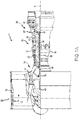
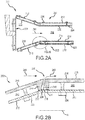
FIGS. 2A and 2B are cross sectional schematic views of a combustor section and a panel configuration within a combustor section, in accordance with various embodiments; -
FIGS. 3A, 3B, 3C, 3D and3E are cross sectional views of combustor panels illustrating a series of steps employed to form a combustor panel rail, in accordance with various embodiments; and -
FIG. 4 is a flowchart that illustrates a series of steps used to fabricate a pair of adjacently positioned panels, in accordance with various embodiments. - The following detailed description of various embodiments herein makes reference to the accompanying drawings, which show various embodiments by way of illustration. While these various embodiments are described in sufficient detail to enable those skilled in the art to practice the disclosure, it should be understood that other embodiments may be realized and that changes may be made without departing from the scope of the disclosure. Thus, the detailed description herein is presented for purposes of illustration only and not of limitation. Furthermore, any reference to singular includes plural embodiments, and any reference to more than one component or step may include a singular embodiment or step. Also, any reference to attached, fixed, connected, or the like may include permanent, removable, temporary, partial, full or any other possible attachment option. Additionally, any reference to without contact (or similar phrases) may also include reduced contact or minimal contact. It should also be understood that unless specifically stated otherwise, references to "a," "an" or "the" may include one or more than one and that reference to an item in the singular may also include the item in the plural. Further, all ranges may include upper and lower values and all ranges and ratio limits disclosed herein may be combined.
- Referring now to the drawings,
FIG. 1A schematically illustrates agas turbine engine 20. Thegas turbine engine 20 is disclosed herein as a two-spool turbofan that generally incorporates afan section 22, acompressor section 24, acombustor section 26 and aturbine section 28. Thefan section 22 drives air along a bypass flow path B in a bypass duct defined within anacelle 15, while thecompressor section 24 drives air along a primary or core flow path C for compression and communication into thecombustor section 26 and then expansion through theturbine section 28. Although depicted as a two-spool turbofan gas turbine engine in the disclosed non-limiting embodiment, it will be understood that the concepts described herein are not limited to use with two-spool turbofans, as the teachings may be applied to other types of turbine engines, including three-spool architectures. - The
gas turbine engine 20 generally includes alow speed spool 30 and ahigh speed spool 32 mounted for rotation about an engine central longitudinal axis A relative to an enginestatic structure 36 viaseveral bearing systems 38. It should be understood that various bearing systems at various locations may alternatively or additionally be provided and the location of theseveral bearing systems 38 may be varied as appropriate to the application. Thelow speed spool 30 generally includes aninner shaft 40 that interconnects afan 42, a low pressure compressor 44 and alow pressure turbine 46. Theinner shaft 40 is connected to thefan 42 through a speed change mechanism, which in thisgas turbine engine 20 is illustrated as a fan drive gear system 48 configured to drive thefan 42 at a lower speed than thelow speed spool 30. Thehigh speed spool 32 includes anouter shaft 50 that interconnects ahigh pressure compressor 52 and a high pressure turbine 54. Acombustor 56 is arranged in thegas turbine engine 20 between thehigh pressure compressor 52 and the high pressure turbine 54. Amid-turbine frame 57 of the enginestatic structure 36 is arranged generally between the high pressure turbine 54 and thelow pressure turbine 46 and may includeairfoils 59 in the core flow path C for guiding the flow into thelow pressure turbine 46. Themid-turbine frame 57 further supports theseveral bearing systems 38 in theturbine section 28. Theinner shaft 40 and theouter shaft 50 are concentric and rotate via theseveral bearing systems 38 about the engine central longitudinal axis A, which is collinear with longitudinal axes of theinner shaft 40 and theouter shaft 50. - The air in the core flow path C is compressed by the low pressure compressor 44 and then the
high pressure compressor 52, mixed and burned with fuel in thecombustor 56, and then expanded over the high pressure turbine 54 andlow pressure turbine 46. Thelow pressure turbine 46 and the high pressure turbine 54 rotationally drive the respectivelow speed spool 30 and thehigh speed spool 32 in response to the expansion. It will be appreciated that each of the positions of thefan section 22, thecompressor section 24, thecombustor section 26, theturbine section 28, and the fan drive gear system 48 may be varied. For example, the fan drive gear system 48 may be located aft of thecombustor section 26 or even aft of theturbine section 28, and thefan section 22 may be positioned forward or aft of the location of the fan drive gear system 48. - Referring to
FIG. 1B , thecombustor 56 may generally include anouter liner assembly 60, aninner liner assembly 62 and adiffuser case module 64 that surrounds theouter liner assembly 60 and theinner liner assembly 62. Acombustion chamber 66, positioned within thecombustor 56, has a generally annular configuration, defined by and comprising theouter liner assembly 60, theinner liner assembly 62 and abulkhead liner assembly 88. Theouter liner assembly 60 and theinner liner assembly 62 are generally cylindrical and radially spaced apart, with thebulkhead liner assembly 88 positioned generally at a forward end of thecombustion chamber 66. Theouter liner assembly 60 is spaced radially inward from anouter diffuser case 68 of thediffuser case module 64 to define an outerannular plenum 70. Theinner liner assembly 62 is spaced radially outward from aninner diffuser case 72 of thediffuser case module 64 to define, in-part, an innerannular plenum 74. Although a particular combustor is illustrated, it should be understood that other combustor types with various combustor liner arrangements will also benefit from this disclosure. - The
combustion chamber 66 contains the combustion products that flow axially toward theturbine section 28. Theouter liner assembly 60 includes anouter support shell 76 and theinner liner assembly 62 includes an inner support shell 78. Theouter support shell 76 supports one or moreouter panels 80 and the inner support shell 78 supports one or more inner panels 82. Each of theouter panels 80 and the inner panels 82 may be formed of a plurality of floating panels that are generally rectilinear and manufactured from, for example, a nickel based super alloy that may be coated with a ceramic or other temperature resistant material, and are arranged to form a panel configuration mounted to the respectiveouter support shell 76 and inner support shell 78. In various embodiments, the combination of theouter support shell 76 and theouter panels 80 is referred to an outer heat shield or outer heat shield liner, while the combination of the inner support shell 78 and the inner panels 82 is referred to as an inner heat shield or inner heat shield liner. In various embodiments, the panels are secured to the shells via one or more attachment mechanisms 75, which may each comprise a threaded stud and nut assembly. - The
combustor 56 further includes aforward assembly 84 that receives compressed airflow from thecompressor section 24 located immediately upstream. Theforward assembly 84 generally includes anannular hood 86, thebulkhead liner assembly 88, and a plurality of swirlers 90 (one shown). Each of theswirlers 90 is aligned with a respective one of a plurality of fuel nozzles 92 (one shown) and a respective one of a plurality of hood ports 94 (one shown) to project through thebulkhead liner assembly 88; generally, the pluralities ofswirlers 90,fuel nozzles 92 andhood ports 94 are circumferentially distributed about theannular hood 86 and thebulkhead liner assembly 88. Thebulkhead liner assembly 88 includes abulkhead support shell 96 secured to theouter liner assembly 60 and to theinner liner assembly 62 and a plurality ofbulkhead panels 98 secured to thebulkhead support shell 96; generally, thebulkhead panels 98 are circumferentially distributed about thebulkhead liner assembly 88. Thebulkhead support shell 96 is generally annular and the plurality ofbulkhead panels 98 is segmented, typically one panel to each of thefuel nozzles 92 andswirlers 90. Theannular hood 86 extends radially between, and is secured to, the forward-most ends of theouter liner assembly 60 and theinner liner assembly 62. Each of thehood ports 94 receives a respective one of the plurality offuel nozzles 92 and facilitates the direction of compressed air into the forward end of thecombustion chamber 66 through a respective one of a plurality ofswirler openings 100. Each of thefuel nozzles 92 may be secured to thediffuser case module 64 and project through a respective one of thehood ports 94 and into a respective one of theswirlers 90. - The
forward assembly 84 introduces core compressed air into the forward section of thecombustion chamber 66 while the remainder of the compressed air enters the outerannular plenum 70 and the innerannular plenum 74. The plurality offuel nozzles 92 and adjacent structure generate a blended fuel-air mixture that supports stable combustion in thecombustion chamber 66. Air in the outerannular plenum 70 and the inner annular plenum is also introduced into thecombustion chamber 66 via a plurality oforifices 116, which may include dilution holes or air feed holes of various dimension. Theouter support shell 76 may also include a plurality of impingement holes (discussed further below) that introduce cooling air from the outerannular plenum 70 into a space between theouter support shell 76 and a cool side of theouter panels 80. The cooling air is then communicated through a plurality of effusion holes in theouter panels 80 to form a cooling air film across a hot side of theouter panels 80 to thermally protect theouter panels 80 from hot combustion gases. Similarly, the inner support shell 78 may include a plurality of impingement holes that introduce cooling air from the innerannular plenum 74 into a space between the inner support shell 78 and a cool side of the inner panels 82. The cooling air is then communicated through a plurality of effusion holes in the inner panels 82 to form a cooling air film across a hot side of the inner panels 82 to thermally protect the inner panels 82 from hot combustion gases. - Turning now to
FIG. 1C (with continued reference toFIG. 1B ), an illustration of a configuration of circumferentially adjacentfirst panels 126 and circumferentially adjacentsecond panels 128 installed within thecombustor 56 is shown. The circumferentially adjacentfirst panels 126 are installed to extend circumferentially about thecombustion chamber 66 and form a first axially extendinggap 136 between the circumferentially adjacentfirst panels 126. Similarly, the circumferentially adjacentsecond panels 128 are installed to extend circumferentially about thecombustion chamber 66 and form a second axially extendinggap 138 between the circumferentially adjacentsecond panels 128. A first circumferentially extendinggap 134 is also formed between the circumferentially adjacentfirst panels 126 and the circumferentially adjacentsecond panels 128 when positioned axially adjacent one another. Similar axially extending and circumferentially extending gaps are formed between similar panels positioned throughout thecombustion chamber 66. The first circumferentially extendinggap 134, the first axially extendinggap 136 and the second axially extendinggap 138 accommodate movement or thermal expansion of the circumferentially adjacentfirst panels 126 and the circumferentially adjacentsecond panels 128. Also shown inFIG. 1C is a plurality oforifices 116, that may include dilution holes or air feed holes of various dimension, a plurality of effusion holes 152 and a shield attachment mechanism, which includes astud 150 and a plurality of spacer pins 154. - Referring now to
FIGS. 2A and 2B , a schematic view of acombustor 200 and a close-up schematic view of a portion of aninner liner assembly 202, respectively, are illustrated, in accordance with various embodiments. In various embodiments, the combustor 200 shares many of the features of thecombustor 56 above described with reference toFIG. 1C . For example, in various embodiments, thecombustor 200 may generally include anouter liner assembly 204 and the inner liner assembly 262. Acombustion chamber 206, positioned within thecombustor 200, has a generally annular configuration, defined by and comprising theouter liner assembly 204, theinner liner assembly 202 and abulkhead liner assembly 208. Theouter liner assembly 204 and theinner liner assembly 202 are generally cylindrical and radially spaced apart, with thebulkhead liner assembly 208 positioned generally at a forward end of thecombustion chamber 206. Theinner liner assembly 202 includes aninner support shell 210 and theouter liner assembly 204 includes anouter support shell 212. Theinner support shell 210 supports one or moreinner panels 214, such as, for example, a firstinner panel 216 and a secondinner panel 218. Similarly, theouter support shell 212 supports one or moreouter panels 220, such as, for example, a firstouter panel 222 and a secondouter panel 224. Each of theinner panels 214 and theouter panels 220 may be formed of a plurality of floating panels that are generally rectilinear and manufactured from, for example, a nickel based super alloy that may be coated with a ceramic or other temperature resistant material, and are arranged to form a panel configuration mounted to the respectiveinner support shell 210 andouter support shell 212. In various embodiments, the combination of theinner support shell 210 and theinner panels 214 is referred to an inner heat shield or inner heat shield liner, while the combination of theouter support shell 212 and theouter panels 220 is referred to as an outer heat shield or outer heat shield liner. In various embodiments, the panels are secured to the shells via one ormore attachment mechanisms 226, which may each comprise a threaded stud and nut assembly. - Referring more specifically to
FIG. 2B , a close-up schematic view of a portion of theinner liner assembly 202 is illustrated, in accordance with various embodiments. In various embodiments, as above described with reference toFIG. 2A , theinner liner assembly 202 comprises the firstinner panel 216 and the secondinner panel 218 secured to theinner support shell 210. The firstinner panel 216 and the secondinner panel 218 generally extend axially with respect to an engine central longitudinal axis A. In various embodiments, agap 230 extends circumferentially between anaft rail 232 of the firstinner panel 216 and aforward rail 234 of the secondinner panel 218. In various embodiments, anaft wall 236 of the aft rail 232 (or the forward or first inner panel 216) and aforward wall 238 of the forward rail 234 (of the aft or second inner panel 218) are spaced apart and configured to provide agap stream 240 flowing from thegap 230 to mix with amain gas stream 241 flowing through the combustor. In various embodiments, thegap stream 240 may comprise cooling air flowing from afirst cavity 242, defined by the space between the firstinner panel 216 and theinner support shell 210, through a first rail impingement hole 244 (or first plurality of impingement holes) into thegap 230, and from asecond cavity 246, defined by the space between the secondinner panel 218 and theinner support shell 210, through a second rail impingement hole 248 (or second plurality of impingement holes) into thegap 230. In various embodiments, thegap stream 240 may also comprise cooling fluid that might leak between spaces occurring between theaft rail 232 and theinner support shell 210 and theforward rail 234 and theinner support shell 210. In various embodiments, and as described further below, theaft wall 236 and theforward wall 238 are configured to reside substantially parallel to one another, thereby reducing entrainment or recirculation of themain gas stream 241 flowing through thecombustor 200. - In various embodiments, the
aft rail 232 and theforward rail 234 are components or sections of, respectively, peripherally extending rail members that extend about the periphery or perimeter of the firstinner panel 216 and the secondinner panel 218. In various embodiments, theaft rail 232, together with three additional rails (as illustrated, for example, inFIG. 1C ), define, in part, a boundary wall that extends lengthwise about all four sides of the firstinner panel 216 at or near the periphery or perimeter of the firstinner panel 216. Likewise, in various embodiments, theforward rail 234, together with three additional rails (as illustrated, for example, inFIG. 1C ), define, in part, a boundary wall that extends lengthwise about all four sides of the secondinner panel 218 at or near the periphery or perimeter of the secondinner panel 218. In various embodiments, the boundary walls extends continuously about or near the periphery or perimeter of the firstinner panel 216 and the secondinner panel 218. In various embodiments, the boundary walls project in a radial direction from the inner panels (or outer panels) and are configured to make contact with or abut the surfaces of the corresponding inner or outer support shells, thereby defining a cooling chamber between the panels and the corresponding inner or outer shells. - Referring now to
FIGS. 3A, 3B, 3C, 3D and3E , a series of steps involved in fabricating an adjacent pair of panels, such as, for example, the firstinner panel 216 and the secondinner panel 218, described above with reference toFIG. 2B , having a gap there between defined by substantially parallel walls, is described. Referring toFIG. 3A , afirst panel 316 and asecond panel 318, having afirst rail 332 and asecond rail 334, respectively, are fabricated, using techniques such as, for example, casting or additive manufacture. In various embodiments, following fabrication, thefirst rail 332 may be characterized as having a firstouter wall 350 that is substantially perpendicular to a firsthot side surface 352 of thefirst panel 316 and a firstinner wall 354 that is substantially perpendicular to a firstcold side surface 356 of thefirst panel 316. Similarly, in various embodiments, following fabrication, thesecond rail 334 may be characterized as having a secondouter wall 360 that is substantially perpendicular to a secondhot side surface 362 of thesecond panel 318 and a secondinner wall 364 that is substantially perpendicular to a secondcold side surface 366 of thesecond panel 318. Reference to being perpendicular is, here, with respect to axial directions along the panel surfaces (e.g., the hot and cold surfaces) and, therefore, contemplates any curvature of the panel in the circumferential direction. - Referring now to
FIGS. 3B and 3C , afirst cutting angle 370 associated with thefirst rail 332 of thefirst panel 316 and asecond cutting angle 372 associated with thesecond rail 334 of thesecond panel 318 are determined, according to the respective orientations of thefirst panel 316 and thesecond panel 318 when secured to a support shell 310 (seeFIG. 3D ). In various embodiments, thefirst cutting angle 370 extends from afirst corner 374, defined by an intersection of the firstouter wall 350 and the firsthot side surface 352, in a direction toward the firstcold side surface 356. Similarly, in various embodiments, thesecond cutting angle 372 extends from asecond corner 376, defined by an intersection of the secondouter wall 360 and ashelf surface 361 of thesecond rail 334, in a direction toward the secondhot side surface 362. Following determination of thefirst cutting angle 370, afirst portion 380 of thefirst rail 332 is removed, e.g., by machining away thefirst portion 380. Similarly, following determination of thesecond cutting angle 372, asecond portion 382 of thesecond rail 334 is removed, e.g., by machining away thesecond portion 382. In various embodiments, the machining away of thefirst portion 380 and thesecond portion 382 is performed by grinding or cutting or other suitable means. - Following the machining away of the
first portion 380 and thesecond portion 382, respectively, thefirst rail 332 of thefirst panel 316 includes a first angledouter wall 336 and thesecond rail 334 of thesecond panel 318 includes a second angledouter wall 338. In various embodiments, following the machining away of thefirst portion 380 and thesecond portion 382, respectively, thefirst rail 332 will include a first distal tip 384 having a firstdistal tip length 385 and thesecond rail 334 will include a seconddistal tip 386 having a second distal tip length 397. In various embodiments, the firstdistal tip length 385 will have a value less than the seconddistal tip length 387; excepting, however, those embodiments where the angle α (seeFIG. 3D ) is equal to zero. In various embodiments, both prior to and following the machining away of thefirst portion 380 and thesecond portion 382, respectively, thefirst rail 332 will have afirst rail thickness 381 defined by a distance between the firsthot side surface 352 and the first distal tip 384 and thesecond rail 334 will have asecond rail thickness 383 defined by a distance between the secondhot side surface 362 and the seconddistal tip 386. In various embodiments, both prior to and following the machining away of thefirst portion 380 and thesecond portion 382, thefirst rail thickness 381 is equal to thesecond rail thickness 383. In various embodiments, one or more first impingement holes 344 are drilled into thefirst rail 332 and one or more second impingement holes 348 are drilled into thesecond rail 334. - Referring now to
FIG. 3D , thefirst panel 316 and thesecond panel 318 are illustrated secured to thesupport shell 310. As illustrated, agap 330, through which a gap stream may flow, is characterized as having a substantially parallel geometry between thefirst rail 332 and thesecond rail 334, as a result of the first angledouter wall 336 being cut at thefirst cutting angle 370 and the second angledouter wall 338 being cut at thesecond cutting angle 372. In various embodiments, where thefirst panel 316 and thesecond panel 318 are substantially similar in geometry - e.g., where afirst thickness 390 of thefirst panel 316 and asecond thickness 392 of thesecond panel 318 are the same and where the dimensions of thefirst rail 332 and thesecond rail 334, prior to cutting, are the same - thefirst cutting angle 370 and thesecond cutting angle 372 may be related by the relative positioning of the panels. For example, in various embodiments, thesupport shell 310 is configured to orient thefirst panel 316 and thesecond panel 318 at an angle α with respect to each other. In various embodiments, the angle α may be defined as the angular difference in orientation of the firsthot side surface 352 and the secondhot side surface 362 with respect to axial lines on the panel surfaces in the direction of a longitudinal axis L. - Referring to
FIG. 3E (with continued reference toFIG. 3D ), a geometric interpretation of thefirst cutting angle 370 and thesecond cutting angle 372 with respect to the angle α and to a second angle β is provided. In various embodiments, for a given angle α, thefirst cutting angle 370 and thesecond cutting angle 372 may be described as a function of the second angle β which, in various embodiments, may take on a value from 0 ≤ β ≤ α. Thus, for example, in various embodiments, where β = α, the first cutting angle 370 (also depicted as θ) will equal twice α (or 2α) and thesecond cutting angle 372 will equal ninety degrees minus α (or 90° - α). Similarly, in various embodiments, where β = 0, thefirst cutting angle 370 will equal α and thesecond cutting angle 372 will equal ninety degrees (or 90°). In various embodiments, for a given α, the second angle β can also be described as running from -α ≤ β < 0, with the result being thegap 330 is oriented such that the gap stream (e.g., thegap stream 240 described above with reference toFIG. 2B ) includes a vector component oriented in a direction against the main gas stream (e.g., themain gas stream 241, also described above with reference toFIG. 2B ). - Referring now to
FIG. 4 , aflowchart 400 is provided that illustrates a series of steps used to fabricate a pair of adjacently positioned panels that define a parallel gap between adjacently positioned rails corresponding to the panels. In afirst step 410, a first panel having a first rail is fabricated and a second panel having a second rail is fabricated. In various embodiments, the fabrication is carried out using casting or additive manufacturing processes. In asecond step 420, a first cutting angle associated with the first rail is determined and a second cutting angle associated with the second rail is determined. In various embodiments, the first cutting angle and the second cutting angle are determined such that a parallel gap between the first rail and the second rail results following assembly on a shelf. In various embodiments, the first cutting angle and the second cutting angle may be determined by geometric formula based on the geometry of the shelf. In athird step 430, a first portion from the first rail corresponding with the first cutting angle is removed to expose a first angled outer wall. In afourth step 440, a second portion from the second rail corresponding with the second cutting angle is removed to expose a second angled outer wall. In various embodiments, the removal is carried out by grinding or cutting processes. In afifth step 450, one or more first impingement holes are drilled into the first rail and one or more second impingement holes are drilled into the second rail. In asixth step 460, the resulting first panel and second panel are assembled to the shelf, such that a gap having parallel sides is formed between the first angled outer wall and the second angled outer wall. In various embodiments, additional steps are performed on the first and second panels, such as, for example, application of metallic or ceramic coatings and the drilling of impingement or effusion holes or dilution holes. - Finally, it should be understood that any of the above described concepts can be used alone or in combination with any or all of the other above described concepts. Although various embodiments have been disclosed and described, one of ordinary skill in this art would recognize that certain modifications would come within the scope of this disclosure. Accordingly, the description is not intended to be exhaustive or to limit the principles described or illustrated herein to any precise form. Many modifications and variations are possible in light of the above teaching.
- Benefits, other advantages, and solutions to problems have been described herein with regard to specific embodiments. Furthermore, the connecting lines shown in the various figures contained herein are intended to represent exemplary functional relationships and/or physical couplings between the various elements. It should be noted that many alternative or additional functional relationships or physical connections may be present in a practical system. However, the benefits, advantages, solutions to problems, and any elements that may cause any benefit, advantage, or solution to occur or become more pronounced are not to be construed as critical, required, or essential features or elements of the disclosure. The scope of the disclosure is accordingly to be limited by nothing other than the appended claims, in which reference to an element in the singular is not intended to mean "one and only one" unless explicitly so stated, but rather "one or more." Moreover, where a phrase similar to "at least one of A, B, or C" is used in the claims, it is intended that the phrase be interpreted to mean that A alone may be present in an embodiment, B alone may be present in an embodiment, C alone may be present in an embodiment, or that any combination of the elements A, B and C may be present in a single embodiment; for example, A and B, A and C, B and C, or A and B and C. Different cross-hatching is used throughout the figures to denote different parts but not necessarily to denote the same or different materials.
- Systems, methods and apparatus are provided herein. In the detailed description herein, references to "one embodiment", "an embodiment", "various embodiments", etc., indicate that the embodiment described may include a particular feature, structure, or characteristic, but every embodiment may not necessarily include the particular feature, structure, or characteristic. Moreover, such phrases are not necessarily referring to the same embodiment. Further, when a particular feature, structure, or characteristic is described in connection with an embodiment, it is submitted that it is within the knowledge of one skilled in the art to affect such feature, structure, or characteristic in connection with other embodiments whether or not explicitly described. After reading the description, it will be apparent to one skilled in the relevant art(s) how to implement the disclosure in alternative embodiments.
- Furthermore, no element, component, or method step in the present disclosure is intended to be dedicated to the public regardless of whether the element, component, or method step is explicitly recited in the claims. As used herein, the terms "comprises", "comprising", or any other variation thereof, are intended to cover a non-exclusive inclusion, such that a process, method, article, or apparatus that comprises a list of elements does not include only those elements but may include other elements not expressly listed or inherent to such process, method, article, or apparatus.
Claims (15)
- A heat shield panel arrangement for use in a combustor of a gas turbine engine, comprising:a first panel having a first rail, the first rail having a first distal tip and a first angled outer wall, the first distal tip having a first distal tip length; anda second panel having a second rail, the second rail having a second distal tip and a second angled outer wall, the second distal tip having a second distal tip length;
wherein the first distal tip length is less than the second distal tip length and wherein the first angled outer wall is substantially parallel to the second angled outer wall with a gap formed therebetween. - The heat shield panel arrangement of claim 1, wherein the first panel and the second panel are disposed in an axial direction along the combustor and wherein the gap extends in a circumferential direction about the combustor.
- The heat shield panel arrangement of claim 1 or 2, wherein the first panel is disposed at a first angle with respect to a longitudinal axis and the second panel is disposed at a second angle with respect to the longitudinal axis.
- The heat shield panel arrangement of claim 3, wherein a relative disposition between the first panel and the second panel defines an angular difference equal to the difference between the first angle and the second angle.
- The heat shield panel arrangement of claim 4, wherein the first angled outer wall is oriented with respect to a first panel hot side surface at a first cutting-angle that is equal to about twice the angular difference.
- The heat shield panel arrangement of claim 5, wherein the second angled outer wall is oriented with respect to a second panel hot side surface at a second cutting-angle that is equal to about ninety degrees minus the angular difference.
- The heat shield panel arrangement of any preceding claim, wherein the first rail is part of a first boundary wall extending peripherally about the first panel and the second rail is part of a second boundary wall extending peripherally about the second panel.
- The heat shield panel arrangement of any preceding claim, wherein the first rail includes a first plurality of impingement holes extending through the first rail from a first inner wall to the first angled outer wall and the second rail includes a second plurality of impingement holes extending through the second rail from a second inner wall to the second angled outer wall.
- A gas turbine engine, comprising:a combustor; anda heat shield panel arrangement for use in the combustor, comprising:a first panel having a first rail, the first rail having a first distal tip and a first angled outer wall, the first distal tip having a first distal tip length; anda second panel having a second rail, the second rail having a second distal tip and a second angled outer wall, the second distal tip having a second distal tip length;
wherein the first distal tip length is less than the second distal tip length and wherein the first angled outer wall is substantially parallel to the second angled outer wall. - The gas turbine engine of claim 9, wherein a gap is formed between the first angled outer wall and the second angled outer wall, the first panel and the second panel are optionally disposed in an axial direction along the combustor and the gap optionally extends in a circumferential direction about the combustor.
- The gas turbine engine of claim 9 or 10, wherein the first rail includes a first plurality of impingement holes extending through the first rail from a first inner wall to the first angled outer wall and wherein the second rail includes a second plurality of impingement holes extending through the second rail from a second inner wall to the second angled outer wall.
- A method of forming a panel arrangement for use in a combustor, comprising:fabricating a first panel having a first rail and a second panel having a second rail;determining a first cutting angle associated with the first rail and a second cutting angle associated with the second rail;removing a first portion from the first rail corresponding with the first cutting angle to expose a first angled outer wall;removing a second portion from the second rail corresponding with the second cutting angle to expose a second angled outer wall; andassembling the first panel and the second panel to a support shell, such that a gap having parallel sides is formed between the first angled outer wall and the second angled outer wall.
- The method of claim 12, wherein the first panel and the second panel are configured for disposition in an axial direction along the combustor and wherein the gap is configured to extend in a circumferential direction about the combustor.
- The method of claim 12 or 13, further comprising drilling one or more first impingement holes into the first rail and drilling one or more second impingement holes into the second rail.
- The heat shield panel arrangement of any of claims 1-8, or the gas turbine engine of claim 9, 10 or 11, or the method of claim 12, 13 or 14, wherein:the first rail includes a first rail thickness and the second rail includes a second rail thickness equal to the first rail thickness; and/orthe first panel includes a first panel thickness and the second panel includes a second panel thickness equal to the first panel thickness.
Applications Claiming Priority (1)
| Application Number | Priority Date | Filing Date | Title |
|---|---|---|---|
| US16/052,242 US10995955B2 (en) | 2018-08-01 | 2018-08-01 | Combustor panel |
Publications (2)
| Publication Number | Publication Date |
|---|---|
| EP3604927A1 true EP3604927A1 (en) | 2020-02-05 |
| EP3604927B1 EP3604927B1 (en) | 2023-04-05 |
Family
ID=67539284
Family Applications (1)
| Application Number | Title | Priority Date | Filing Date |
|---|---|---|---|
| EP19189636.4A Active EP3604927B1 (en) | 2018-08-01 | 2019-08-01 | Liner assembly for use in a combustor of a gas turbine engine combustor panel |
Country Status (2)
| Country | Link |
|---|---|
| US (1) | US10995955B2 (en) |
| EP (1) | EP3604927B1 (en) |
Families Citing this family (5)
| Publication number | Priority date | Publication date | Assignee | Title |
|---|---|---|---|---|
| US10830435B2 (en) | 2018-02-06 | 2020-11-10 | Raytheon Technologies Corporation | Diffusing hole for rail effusion |
| US11009230B2 (en) | 2018-02-06 | 2021-05-18 | Raytheon Technologies Corporation | Undercut combustor panel rail |
| US11248791B2 (en) | 2018-02-06 | 2022-02-15 | Raytheon Technologies Corporation | Pull-plane effusion combustor panel |
| US11022307B2 (en) | 2018-02-22 | 2021-06-01 | Raytheon Technology Corporation | Gas turbine combustor heat shield panel having multi-direction hole for rail effusion cooling |
| US12352442B1 (en) * | 2024-07-01 | 2025-07-08 | Rtx Corporation | Combustor panel with rail integrated perimeter studs |
Citations (5)
| Publication number | Priority date | Publication date | Assignee | Title |
|---|---|---|---|---|
| US20160238248A1 (en) * | 2013-10-07 | 2016-08-18 | United Technologies Corporation | Bonded combustor wall for a turbine engine |
| US20170176005A1 (en) * | 2015-12-17 | 2017-06-22 | Rolls-Royce Plc | Combustion chamber |
| US20180073737A1 (en) * | 2016-09-15 | 2018-03-15 | United Technologies Corporation | Wall panel assembly for a gas turbine engine |
| EP3404329A1 (en) * | 2017-05-18 | 2018-11-21 | United Technologies Corporation | Combustor panel endrail interface |
| EP3415819A1 (en) * | 2017-06-15 | 2018-12-19 | United Technologies Corporation | Comburstor liner panel end rail with diffused interface passage for a gas turbine engine combustor |
Family Cites Families (5)
| Publication number | Priority date | Publication date | Assignee | Title |
|---|---|---|---|---|
| FR2752916B1 (en) | 1996-09-05 | 1998-10-02 | Snecma | THERMAL PROTECTIVE SHIRT FOR TURBOREACTOR COMBUSTION CHAMBER |
| WO2008017551A2 (en) * | 2006-08-07 | 2008-02-14 | Alstom Technology Ltd | Combustion chamber of a combustion plant |
| US10260750B2 (en) * | 2015-12-29 | 2019-04-16 | United Technologies Corporation | Combustor panels having angled rail |
| GB201603166D0 (en) | 2016-02-24 | 2016-04-06 | Rolls Royce Plc | A combustion chamber |
| US11035572B2 (en) | 2018-06-28 | 2021-06-15 | Raytheon Technologies Corporation | Heat shield panel manufacturing process |
-
2018
- 2018-08-01 US US16/052,242 patent/US10995955B2/en active Active
-
2019
- 2019-08-01 EP EP19189636.4A patent/EP3604927B1/en active Active
Patent Citations (5)
| Publication number | Priority date | Publication date | Assignee | Title |
|---|---|---|---|---|
| US20160238248A1 (en) * | 2013-10-07 | 2016-08-18 | United Technologies Corporation | Bonded combustor wall for a turbine engine |
| US20170176005A1 (en) * | 2015-12-17 | 2017-06-22 | Rolls-Royce Plc | Combustion chamber |
| US20180073737A1 (en) * | 2016-09-15 | 2018-03-15 | United Technologies Corporation | Wall panel assembly for a gas turbine engine |
| EP3404329A1 (en) * | 2017-05-18 | 2018-11-21 | United Technologies Corporation | Combustor panel endrail interface |
| EP3415819A1 (en) * | 2017-06-15 | 2018-12-19 | United Technologies Corporation | Comburstor liner panel end rail with diffused interface passage for a gas turbine engine combustor |
Also Published As
| Publication number | Publication date |
|---|---|
| EP3604927B1 (en) | 2023-04-05 |
| US20200041126A1 (en) | 2020-02-06 |
| US10995955B2 (en) | 2021-05-04 |
Similar Documents
| Publication | Publication Date | Title |
|---|---|---|
| EP3604927B1 (en) | Liner assembly for use in a combustor of a gas turbine engine combustor panel | |
| US11009230B2 (en) | Undercut combustor panel rail | |
| US10151486B2 (en) | Cooled grommet for a combustor wall assembly | |
| US9810148B2 (en) | Self-cooled orifice structure | |
| US9851105B2 (en) | Self-cooled orifice structure | |
| US11725816B2 (en) | Multi-direction hole for rail effusion | |
| EP3839348A1 (en) | Combustor panel | |
| EP3628927B1 (en) | Heat shield panel | |
| EP3524885B1 (en) | Combustor panel standoff pin | |
| EP3951266B1 (en) | Method of forming an orifice through a rail member of a heat shield panel | |
| EP3779281A1 (en) | Aerodynamic guide plate collar for swirler assembly | |
| EP3521574B1 (en) | Heat shield panel with cooling holes and method for manufacturing it | |
| EP3604926B1 (en) | Heat shield panel for use in a gas turbine engine combustor |
Legal Events
| Date | Code | Title | Description |
|---|---|---|---|
| PUAI | Public reference made under article 153(3) epc to a published international application that has entered the european phase |
Free format text: ORIGINAL CODE: 0009012 |
|
| STAA | Information on the status of an ep patent application or granted ep patent |
Free format text: STATUS: THE APPLICATION HAS BEEN PUBLISHED |
|
| AK | Designated contracting states |
Kind code of ref document: A1 Designated state(s): AL AT BE BG CH CY CZ DE DK EE ES FI FR GB GR HR HU IE IS IT LI LT LU LV MC MK MT NL NO PL PT RO RS SE SI SK SM TR |
|
| AX | Request for extension of the european patent |
Extension state: BA ME |
|
| STAA | Information on the status of an ep patent application or granted ep patent |
Free format text: STATUS: REQUEST FOR EXAMINATION WAS MADE |
|
| 17P | Request for examination filed |
Effective date: 20200805 |
|
| RBV | Designated contracting states (corrected) |
Designated state(s): AL AT BE BG CH CY CZ DE DK EE ES FI FR GB GR HR HU IE IS IT LI LT LU LV MC MK MT NL NO PL PT RO RS SE SI SK SM TR |
|
| STAA | Information on the status of an ep patent application or granted ep patent |
Free format text: STATUS: EXAMINATION IS IN PROGRESS |
|
| 17Q | First examination report despatched |
Effective date: 20201002 |
|
| RAP1 | Party data changed (applicant data changed or rights of an application transferred) |
Owner name: RAYTHEON TECHNOLOGIES CORPORATION |
|
| GRAP | Despatch of communication of intention to grant a patent |
Free format text: ORIGINAL CODE: EPIDOSNIGR1 |
|
| STAA | Information on the status of an ep patent application or granted ep patent |
Free format text: STATUS: GRANT OF PATENT IS INTENDED |
|
| INTG | Intention to grant announced |
Effective date: 20221019 |
|
| GRAS | Grant fee paid |
Free format text: ORIGINAL CODE: EPIDOSNIGR3 |
|
| GRAA | (expected) grant |
Free format text: ORIGINAL CODE: 0009210 |
|
| STAA | Information on the status of an ep patent application or granted ep patent |
Free format text: STATUS: THE PATENT HAS BEEN GRANTED |
|
| AK | Designated contracting states |
Kind code of ref document: B1 Designated state(s): AL AT BE BG CH CY CZ DE DK EE ES FI FR GB GR HR HU IE IS IT LI LT LU LV MC MK MT NL NO PL PT RO RS SE SI SK SM TR |
|
| REG | Reference to a national code |
Ref country code: GB Ref legal event code: FG4D |
|
| REG | Reference to a national code |
Ref country code: DE Ref legal event code: R096 Ref document number: 602019027110 Country of ref document: DE |
|
| REG | Reference to a national code |
Ref country code: CH Ref legal event code: EP |
|
| REG | Reference to a national code |
Ref country code: AT Ref legal event code: REF Ref document number: 1558490 Country of ref document: AT Kind code of ref document: T Effective date: 20230415 |
|
| REG | Reference to a national code |
Ref country code: IE Ref legal event code: FG4D |
|
| P01 | Opt-out of the competence of the unified patent court (upc) registered |
Effective date: 20230521 |
|
| REG | Reference to a national code |
Ref country code: LT Ref legal event code: MG9D |
|
| REG | Reference to a national code |
Ref country code: NL Ref legal event code: MP Effective date: 20230405 |
|
| REG | Reference to a national code |
Ref country code: AT Ref legal event code: MK05 Ref document number: 1558490 Country of ref document: AT Kind code of ref document: T Effective date: 20230405 |
|
| PG25 | Lapsed in a contracting state [announced via postgrant information from national office to epo] |
Ref country code: NL Free format text: LAPSE BECAUSE OF FAILURE TO SUBMIT A TRANSLATION OF THE DESCRIPTION OR TO PAY THE FEE WITHIN THE PRESCRIBED TIME-LIMIT Effective date: 20230405 |
|
| PG25 | Lapsed in a contracting state [announced via postgrant information from national office to epo] |
Ref country code: SE Free format text: LAPSE BECAUSE OF FAILURE TO SUBMIT A TRANSLATION OF THE DESCRIPTION OR TO PAY THE FEE WITHIN THE PRESCRIBED TIME-LIMIT Effective date: 20230405 Ref country code: PT Free format text: LAPSE BECAUSE OF FAILURE TO SUBMIT A TRANSLATION OF THE DESCRIPTION OR TO PAY THE FEE WITHIN THE PRESCRIBED TIME-LIMIT Effective date: 20230807 Ref country code: NO Free format text: LAPSE BECAUSE OF FAILURE TO SUBMIT A TRANSLATION OF THE DESCRIPTION OR TO PAY THE FEE WITHIN THE PRESCRIBED TIME-LIMIT Effective date: 20230705 Ref country code: ES Free format text: LAPSE BECAUSE OF FAILURE TO SUBMIT A TRANSLATION OF THE DESCRIPTION OR TO PAY THE FEE WITHIN THE PRESCRIBED TIME-LIMIT Effective date: 20230405 Ref country code: AT Free format text: LAPSE BECAUSE OF FAILURE TO SUBMIT A TRANSLATION OF THE DESCRIPTION OR TO PAY THE FEE WITHIN THE PRESCRIBED TIME-LIMIT Effective date: 20230405 |
|
| RAP4 | Party data changed (patent owner data changed or rights of a patent transferred) |
Owner name: RTX CORPORATION |
|
| PG25 | Lapsed in a contracting state [announced via postgrant information from national office to epo] |
Ref country code: RS Free format text: LAPSE BECAUSE OF FAILURE TO SUBMIT A TRANSLATION OF THE DESCRIPTION OR TO PAY THE FEE WITHIN THE PRESCRIBED TIME-LIMIT Effective date: 20230405 Ref country code: PL Free format text: LAPSE BECAUSE OF FAILURE TO SUBMIT A TRANSLATION OF THE DESCRIPTION OR TO PAY THE FEE WITHIN THE PRESCRIBED TIME-LIMIT Effective date: 20230405 Ref country code: LV Free format text: LAPSE BECAUSE OF FAILURE TO SUBMIT A TRANSLATION OF THE DESCRIPTION OR TO PAY THE FEE WITHIN THE PRESCRIBED TIME-LIMIT Effective date: 20230405 Ref country code: LT Free format text: LAPSE BECAUSE OF FAILURE TO SUBMIT A TRANSLATION OF THE DESCRIPTION OR TO PAY THE FEE WITHIN THE PRESCRIBED TIME-LIMIT Effective date: 20230405 Ref country code: IS Free format text: LAPSE BECAUSE OF FAILURE TO SUBMIT A TRANSLATION OF THE DESCRIPTION OR TO PAY THE FEE WITHIN THE PRESCRIBED TIME-LIMIT Effective date: 20230805 Ref country code: HR Free format text: LAPSE BECAUSE OF FAILURE TO SUBMIT A TRANSLATION OF THE DESCRIPTION OR TO PAY THE FEE WITHIN THE PRESCRIBED TIME-LIMIT Effective date: 20230405 Ref country code: GR Free format text: LAPSE BECAUSE OF FAILURE TO SUBMIT A TRANSLATION OF THE DESCRIPTION OR TO PAY THE FEE WITHIN THE PRESCRIBED TIME-LIMIT Effective date: 20230706 Ref country code: AL Free format text: LAPSE BECAUSE OF FAILURE TO SUBMIT A TRANSLATION OF THE DESCRIPTION OR TO PAY THE FEE WITHIN THE PRESCRIBED TIME-LIMIT Effective date: 20230405 |
|
| PG25 | Lapsed in a contracting state [announced via postgrant information from national office to epo] |
Ref country code: FI Free format text: LAPSE BECAUSE OF FAILURE TO SUBMIT A TRANSLATION OF THE DESCRIPTION OR TO PAY THE FEE WITHIN THE PRESCRIBED TIME-LIMIT Effective date: 20230405 |
|
| REG | Reference to a national code |
Ref country code: DE Ref legal event code: R097 Ref document number: 602019027110 Country of ref document: DE |
|
| PG25 | Lapsed in a contracting state [announced via postgrant information from national office to epo] |
Ref country code: SK Free format text: LAPSE BECAUSE OF FAILURE TO SUBMIT A TRANSLATION OF THE DESCRIPTION OR TO PAY THE FEE WITHIN THE PRESCRIBED TIME-LIMIT Effective date: 20230405 |
|
| PG25 | Lapsed in a contracting state [announced via postgrant information from national office to epo] |
Ref country code: SM Free format text: LAPSE BECAUSE OF FAILURE TO SUBMIT A TRANSLATION OF THE DESCRIPTION OR TO PAY THE FEE WITHIN THE PRESCRIBED TIME-LIMIT Effective date: 20230405 Ref country code: SK Free format text: LAPSE BECAUSE OF FAILURE TO SUBMIT A TRANSLATION OF THE DESCRIPTION OR TO PAY THE FEE WITHIN THE PRESCRIBED TIME-LIMIT Effective date: 20230405 Ref country code: RO Free format text: LAPSE BECAUSE OF FAILURE TO SUBMIT A TRANSLATION OF THE DESCRIPTION OR TO PAY THE FEE WITHIN THE PRESCRIBED TIME-LIMIT Effective date: 20230405 Ref country code: EE Free format text: LAPSE BECAUSE OF FAILURE TO SUBMIT A TRANSLATION OF THE DESCRIPTION OR TO PAY THE FEE WITHIN THE PRESCRIBED TIME-LIMIT Effective date: 20230405 Ref country code: DK Free format text: LAPSE BECAUSE OF FAILURE TO SUBMIT A TRANSLATION OF THE DESCRIPTION OR TO PAY THE FEE WITHIN THE PRESCRIBED TIME-LIMIT Effective date: 20230405 Ref country code: CZ Free format text: LAPSE BECAUSE OF FAILURE TO SUBMIT A TRANSLATION OF THE DESCRIPTION OR TO PAY THE FEE WITHIN THE PRESCRIBED TIME-LIMIT Effective date: 20230405 |
|
| PLBE | No opposition filed within time limit |
Free format text: ORIGINAL CODE: 0009261 |
|
| STAA | Information on the status of an ep patent application or granted ep patent |
Free format text: STATUS: NO OPPOSITION FILED WITHIN TIME LIMIT |
|
| PG25 | Lapsed in a contracting state [announced via postgrant information from national office to epo] |
Ref country code: MC Free format text: LAPSE BECAUSE OF FAILURE TO SUBMIT A TRANSLATION OF THE DESCRIPTION OR TO PAY THE FEE WITHIN THE PRESCRIBED TIME-LIMIT Effective date: 20230405 |
|
| 26N | No opposition filed |
Effective date: 20240108 |
|
| REG | Reference to a national code |
Ref country code: CH Ref legal event code: PL |
|
| PG25 | Lapsed in a contracting state [announced via postgrant information from national office to epo] |
Ref country code: MC Free format text: LAPSE BECAUSE OF FAILURE TO SUBMIT A TRANSLATION OF THE DESCRIPTION OR TO PAY THE FEE WITHIN THE PRESCRIBED TIME-LIMIT Effective date: 20230405 |
|
| PG25 | Lapsed in a contracting state [announced via postgrant information from national office to epo] |
Ref country code: LU Free format text: LAPSE BECAUSE OF NON-PAYMENT OF DUE FEES Effective date: 20230801 |
|
| PG25 | Lapsed in a contracting state [announced via postgrant information from national office to epo] |
Ref country code: LU Free format text: LAPSE BECAUSE OF NON-PAYMENT OF DUE FEES Effective date: 20230801 Ref country code: CH Free format text: LAPSE BECAUSE OF NON-PAYMENT OF DUE FEES Effective date: 20230831 |
|
| PG25 | Lapsed in a contracting state [announced via postgrant information from national office to epo] |
Ref country code: SI Free format text: LAPSE BECAUSE OF FAILURE TO SUBMIT A TRANSLATION OF THE DESCRIPTION OR TO PAY THE FEE WITHIN THE PRESCRIBED TIME-LIMIT Effective date: 20230405 |
|
| REG | Reference to a national code |
Ref country code: BE Ref legal event code: MM Effective date: 20230831 |
|
| REG | Reference to a national code |
Ref country code: IE Ref legal event code: MM4A |
|
| PG25 | Lapsed in a contracting state [announced via postgrant information from national office to epo] |
Ref country code: SI Free format text: LAPSE BECAUSE OF FAILURE TO SUBMIT A TRANSLATION OF THE DESCRIPTION OR TO PAY THE FEE WITHIN THE PRESCRIBED TIME-LIMIT Effective date: 20230405 Ref country code: IT Free format text: LAPSE BECAUSE OF FAILURE TO SUBMIT A TRANSLATION OF THE DESCRIPTION OR TO PAY THE FEE WITHIN THE PRESCRIBED TIME-LIMIT Effective date: 20230405 |
|
| PG25 | Lapsed in a contracting state [announced via postgrant information from national office to epo] |
Ref country code: IE Free format text: LAPSE BECAUSE OF NON-PAYMENT OF DUE FEES Effective date: 20230801 |
|
| PG25 | Lapsed in a contracting state [announced via postgrant information from national office to epo] |
Ref country code: IE Free format text: LAPSE BECAUSE OF NON-PAYMENT OF DUE FEES Effective date: 20230801 |
|
| PG25 | Lapsed in a contracting state [announced via postgrant information from national office to epo] |
Ref country code: BE Free format text: LAPSE BECAUSE OF NON-PAYMENT OF DUE FEES Effective date: 20230831 |
|
| PG25 | Lapsed in a contracting state [announced via postgrant information from national office to epo] |
Ref country code: BG Free format text: LAPSE BECAUSE OF FAILURE TO SUBMIT A TRANSLATION OF THE DESCRIPTION OR TO PAY THE FEE WITHIN THE PRESCRIBED TIME-LIMIT Effective date: 20230405 |
|
| PG25 | Lapsed in a contracting state [announced via postgrant information from national office to epo] |
Ref country code: BG Free format text: LAPSE BECAUSE OF FAILURE TO SUBMIT A TRANSLATION OF THE DESCRIPTION OR TO PAY THE FEE WITHIN THE PRESCRIBED TIME-LIMIT Effective date: 20230405 |
|
| PG25 | Lapsed in a contracting state [announced via postgrant information from national office to epo] |
Ref country code: CY Free format text: LAPSE BECAUSE OF FAILURE TO SUBMIT A TRANSLATION OF THE DESCRIPTION OR TO PAY THE FEE WITHIN THE PRESCRIBED TIME-LIMIT; INVALID AB INITIO Effective date: 20190801 |
|
| PG25 | Lapsed in a contracting state [announced via postgrant information from national office to epo] |
Ref country code: HU Free format text: LAPSE BECAUSE OF FAILURE TO SUBMIT A TRANSLATION OF THE DESCRIPTION OR TO PAY THE FEE WITHIN THE PRESCRIBED TIME-LIMIT; INVALID AB INITIO Effective date: 20190801 |
|
| REG | Reference to a national code |
Ref country code: DE Ref legal event code: R081 Ref document number: 602019027110 Country of ref document: DE Owner name: RTX CORPORATION (N.D.GES.D. STAATES DELAWARE),, US Free format text: FORMER OWNER: RAYTHEON TECHNOLOGIES CORPORATION, FARMINGTON, CT, US |
|
| PGFP | Annual fee paid to national office [announced via postgrant information from national office to epo] |
Ref country code: DE Payment date: 20250724 Year of fee payment: 7 |
|
| PGFP | Annual fee paid to national office [announced via postgrant information from national office to epo] |
Ref country code: GB Payment date: 20250724 Year of fee payment: 7 |
|
| PGFP | Annual fee paid to national office [announced via postgrant information from national office to epo] |
Ref country code: FR Payment date: 20250723 Year of fee payment: 7 |
|
| PG25 | Lapsed in a contracting state [announced via postgrant information from national office to epo] |
Ref country code: TR Free format text: LAPSE BECAUSE OF FAILURE TO SUBMIT A TRANSLATION OF THE DESCRIPTION OR TO PAY THE FEE WITHIN THE PRESCRIBED TIME-LIMIT Effective date: 20230405 |