EP3604863B1 - Transmission control device - Google Patents
Transmission control device Download PDFInfo
- Publication number
- EP3604863B1 EP3604863B1 EP18770282.4A EP18770282A EP3604863B1 EP 3604863 B1 EP3604863 B1 EP 3604863B1 EP 18770282 A EP18770282 A EP 18770282A EP 3604863 B1 EP3604863 B1 EP 3604863B1
- Authority
- EP
- European Patent Office
- Prior art keywords
- preshift
- plan
- control device
- gear
- automatic driving
- Prior art date
- Legal status (The legal status is an assumption and is not a legal conclusion. Google has not performed a legal analysis and makes no representation as to the accuracy of the status listed.)
- Active
Links
Images




Classifications
-
- F—MECHANICAL ENGINEERING; LIGHTING; HEATING; WEAPONS; BLASTING
- F16—ENGINEERING ELEMENTS AND UNITS; GENERAL MEASURES FOR PRODUCING AND MAINTAINING EFFECTIVE FUNCTIONING OF MACHINES OR INSTALLATIONS; THERMAL INSULATION IN GENERAL
- F16H—GEARING
- F16H61/00—Control functions within control units of change-speed- or reversing-gearings for conveying rotary motion ; Control of exclusively fluid gearing, friction gearing, gearings with endless flexible members or other particular types of gearing
- F16H61/02—Control functions within control units of change-speed- or reversing-gearings for conveying rotary motion ; Control of exclusively fluid gearing, friction gearing, gearings with endless flexible members or other particular types of gearing characterised by the signals used
- F16H61/0202—Control functions within control units of change-speed- or reversing-gearings for conveying rotary motion ; Control of exclusively fluid gearing, friction gearing, gearings with endless flexible members or other particular types of gearing characterised by the signals used the signals being electric
- F16H61/0204—Control functions within control units of change-speed- or reversing-gearings for conveying rotary motion ; Control of exclusively fluid gearing, friction gearing, gearings with endless flexible members or other particular types of gearing characterised by the signals used the signals being electric for gearshift control, e.g. control functions for performing shifting or generation of shift signal
-
- F—MECHANICAL ENGINEERING; LIGHTING; HEATING; WEAPONS; BLASTING
- F16—ENGINEERING ELEMENTS AND UNITS; GENERAL MEASURES FOR PRODUCING AND MAINTAINING EFFECTIVE FUNCTIONING OF MACHINES OR INSTALLATIONS; THERMAL INSULATION IN GENERAL
- F16H—GEARING
- F16H61/00—Control functions within control units of change-speed- or reversing-gearings for conveying rotary motion ; Control of exclusively fluid gearing, friction gearing, gearings with endless flexible members or other particular types of gearing
- F16H61/02—Control functions within control units of change-speed- or reversing-gearings for conveying rotary motion ; Control of exclusively fluid gearing, friction gearing, gearings with endless flexible members or other particular types of gearing characterised by the signals used
- F16H61/0202—Control functions within control units of change-speed- or reversing-gearings for conveying rotary motion ; Control of exclusively fluid gearing, friction gearing, gearings with endless flexible members or other particular types of gearing characterised by the signals used the signals being electric
- F16H61/0204—Control functions within control units of change-speed- or reversing-gearings for conveying rotary motion ; Control of exclusively fluid gearing, friction gearing, gearings with endless flexible members or other particular types of gearing characterised by the signals used the signals being electric for gearshift control, e.g. control functions for performing shifting or generation of shift signal
- F16H61/0213—Control functions within control units of change-speed- or reversing-gearings for conveying rotary motion ; Control of exclusively fluid gearing, friction gearing, gearings with endless flexible members or other particular types of gearing characterised by the signals used the signals being electric for gearshift control, e.g. control functions for performing shifting or generation of shift signal characterised by the method for generating shift signals
-
- F—MECHANICAL ENGINEERING; LIGHTING; HEATING; WEAPONS; BLASTING
- F16—ENGINEERING ELEMENTS AND UNITS; GENERAL MEASURES FOR PRODUCING AND MAINTAINING EFFECTIVE FUNCTIONING OF MACHINES OR INSTALLATIONS; THERMAL INSULATION IN GENERAL
- F16H—GEARING
- F16H61/00—Control functions within control units of change-speed- or reversing-gearings for conveying rotary motion ; Control of exclusively fluid gearing, friction gearing, gearings with endless flexible members or other particular types of gearing
- F16H61/68—Control functions within control units of change-speed- or reversing-gearings for conveying rotary motion ; Control of exclusively fluid gearing, friction gearing, gearings with endless flexible members or other particular types of gearing specially adapted for stepped gearings
- F16H61/684—Control functions within control units of change-speed- or reversing-gearings for conveying rotary motion ; Control of exclusively fluid gearing, friction gearing, gearings with endless flexible members or other particular types of gearing specially adapted for stepped gearings without interruption of drive
- F16H61/688—Control functions within control units of change-speed- or reversing-gearings for conveying rotary motion ; Control of exclusively fluid gearing, friction gearing, gearings with endless flexible members or other particular types of gearing specially adapted for stepped gearings without interruption of drive with two inputs, e.g. selection of one of two torque-flow paths by clutches
-
- B—PERFORMING OPERATIONS; TRANSPORTING
- B60—VEHICLES IN GENERAL
- B60Y—INDEXING SCHEME RELATING TO ASPECTS CROSS-CUTTING VEHICLE TECHNOLOGY
- B60Y2300/00—Purposes or special features of road vehicle drive control systems
- B60Y2300/14—Cruise control
-
- F—MECHANICAL ENGINEERING; LIGHTING; HEATING; WEAPONS; BLASTING
- F16—ENGINEERING ELEMENTS AND UNITS; GENERAL MEASURES FOR PRODUCING AND MAINTAINING EFFECTIVE FUNCTIONING OF MACHINES OR INSTALLATIONS; THERMAL INSULATION IN GENERAL
- F16H—GEARING
- F16H61/00—Control functions within control units of change-speed- or reversing-gearings for conveying rotary motion ; Control of exclusively fluid gearing, friction gearing, gearings with endless flexible members or other particular types of gearing
- F16H61/02—Control functions within control units of change-speed- or reversing-gearings for conveying rotary motion ; Control of exclusively fluid gearing, friction gearing, gearings with endless flexible members or other particular types of gearing characterised by the signals used
- F16H61/0202—Control functions within control units of change-speed- or reversing-gearings for conveying rotary motion ; Control of exclusively fluid gearing, friction gearing, gearings with endless flexible members or other particular types of gearing characterised by the signals used the signals being electric
- F16H61/0204—Control functions within control units of change-speed- or reversing-gearings for conveying rotary motion ; Control of exclusively fluid gearing, friction gearing, gearings with endless flexible members or other particular types of gearing characterised by the signals used the signals being electric for gearshift control, e.g. control functions for performing shifting or generation of shift signal
- F16H61/0213—Control functions within control units of change-speed- or reversing-gearings for conveying rotary motion ; Control of exclusively fluid gearing, friction gearing, gearings with endless flexible members or other particular types of gearing characterised by the signals used the signals being electric for gearshift control, e.g. control functions for performing shifting or generation of shift signal characterised by the method for generating shift signals
- F16H2061/022—Calculation or estimation of optimal gear ratio, e.g. best ratio for economy drive or performance according driver preference, or to optimise exhaust emissions
-
- F—MECHANICAL ENGINEERING; LIGHTING; HEATING; WEAPONS; BLASTING
- F16—ENGINEERING ELEMENTS AND UNITS; GENERAL MEASURES FOR PRODUCING AND MAINTAINING EFFECTIVE FUNCTIONING OF MACHINES OR INSTALLATIONS; THERMAL INSULATION IN GENERAL
- F16H—GEARING
- F16H2306/00—Shifting
- F16H2306/18—Preparing coupling or engaging of future gear
-
- F—MECHANICAL ENGINEERING; LIGHTING; HEATING; WEAPONS; BLASTING
- F16—ENGINEERING ELEMENTS AND UNITS; GENERAL MEASURES FOR PRODUCING AND MAINTAINING EFFECTIVE FUNCTIONING OF MACHINES OR INSTALLATIONS; THERMAL INSULATION IN GENERAL
- F16H—GEARING
- F16H2708/00—Control devices for speed-changing geared mechanisms, e.g. specially adapted couplings for synchronising devices, devices to simplify control, control of auxiliary gearboxes
- F16H2708/16—Control devices for speed-changing geared mechanisms, e.g. specially adapted couplings for synchronising devices, devices to simplify control, control of auxiliary gearboxes wherein the gearing is not described or not essential
- F16H2708/22—Control devices for speed-changing geared mechanisms, e.g. specially adapted couplings for synchronising devices, devices to simplify control, control of auxiliary gearboxes wherein the gearing is not described or not essential the control being electric
-
- F—MECHANICAL ENGINEERING; LIGHTING; HEATING; WEAPONS; BLASTING
- F16—ENGINEERING ELEMENTS AND UNITS; GENERAL MEASURES FOR PRODUCING AND MAINTAINING EFFECTIVE FUNCTIONING OF MACHINES OR INSTALLATIONS; THERMAL INSULATION IN GENERAL
- F16H—GEARING
- F16H59/00—Control inputs to control units of change-speed- or reversing-gearings for conveying rotary motion
- F16H59/60—Inputs being a function of ambient conditions
Definitions
- the present invention relates to a gearshift control device.
- an automated manual transmission (referred to as an "automated MT" below) has been developed.
- gearshift starts, a clutch which transmits or blocks a torque of an engine which is a driving force source is disengaged, the synchronous mesh mechanisms are switched, and then the clutch is engaged again.
- JP 2007-232047 A discloses a method for selecting upshift standby or downshift standby of a preshift gear based on external information obtaining means such as a navigation device, a radar device or a camera device.
- PTL 2 discloses a method of shift control for an automatic transmission of vehicle power train, having a permanent brake between a drive motor and a final drive, in which current vehicle-specific, road-specific and driver-specific operating parameters, topographical data relating to an upcoming stretch of road ahead of the vehicle are determined while driving, and from which a tractive resistance value for the upcoming stretch of road is determined, and control commands for thrust down-shifts and/or upshifts are derived and implemented, within the transmission, during a thrust operation depending upon the tractive resistance value.
- PTL 3 discloses a vehicular control apparatus for a vehicle comprising a twin clutch type automatic transmission.
- PTL 4 discloses an automatic driving system for a vehicle includes an external sensor and an electronic control unit.
- the electronic control unit is configured to estimate whether the vehicle peripheral information detected by the external sensor allows the vehicle to keep a vehicle target speed set on the basis of a vehicle travel plan or temporarily does not allow the vehicle to keep the vehicle target speed.
- Preshift control disclosed in PTL 1 is control of detecting a current traveling gear position, and selecting an upshift side gear position or a downshift side gear position neighbor to the current traveling gear position.
- the present embodiment relates to a control device and a control method of an automatic transmission. More particularly, the present invention relates to the control device and the control method of the automatic transmission which suitably control a gear transmission used for a car.
- a twin clutch automated MT executes preshift of engaging the other (clutch disengage shaft) during traveling using one of an even-numbered shaft or an odd-numbered shaft.
- the preshift makes a non-driven shaft a traveling resistance, and therefore is likely to deteriorate fuel efficiency.
- FIG. 1 is a skeleton diagram of a system configuration example illustrating one embodiment of the control device (gearshift control device) of the car including an automatic transmission according to the present invention.
- An engine 7 which is a driving force source, an engine rotational speed sensor (not illustrated) which measures a rotational speed of the engine 7, an electronic control throttle (not illustrated) which adjusts an engine torque, and a fuel injection device (not illustrated) which injects a fuel amount matching an intake air amount are provided.
- An engine control unit 101 manipulates the intake air amount, the fuel amount and an ignition timing, so that it is possible to precisely control a torque of the engine 7.
- the above-described fuel injection device is an intake port injection system which injects a fuel to an intake port or a cylinder injection system which directly injects the fuel in a cylinder. It is advantageous to use an engine adopting a system which can reduce fuel consumption compared to a driving range (a range determined by an engine torque and an engine rotational speed) requested for the engine, and has good exhaust capability.
- the driving force source may be not only a gasoline engine but also a diesel engine, a natural gas engine and an electric motor.
- An automatic transmission (transmission) 50 includes a first clutch 8, a second clutch 9, a first input shaft 41, a second input shaft 42, an output shaft 43, a first drive gear 1, a second drive gear 2, a reverse drive gear 10, a third drive gear 3, a fourth drive gear 4, a fifth drive gear 5, a sixth drive gear 6, a first driven gear 11, a second driven gear 12, a reverse driven gear 20, a third driven gear 13, a fourth driven gear 14, a fifth driven gear 15, a sixth driven gear 16, an idler gear 30, a first synchronous mesh mechanism 21, a second synchronous mesh mechanism 22, a third synchronous mesh mechanism 23, a fourth synchronous mesh mechanism 24, a rotation sensor 31, a rotation sensor 32 and a rotation sensor 33.
- Multiplate wet clutches are used for the first clutch 8 and the second clutch 9 in the present embodiment.
- dry single plate clutches may be used for the first clutch 8 and the second clutch 9, and all friction transmission mechanisms can be used.
- first clutch 8 and the second clutch 9 can be also composed of electromagnetic powder clutches.
- the second input shaft 42 is hollow, and the first input shaft 41 penetrates the hollow portion of the second input shaft 42, and is configured to be able to make a relative motion in a rotation direction with respect to the second input shaft 42.
- the first drive gear 1, the third drive gear 3, the fifth drive gear 5 and the reverse drive gear 10 are fixed to the second input shaft 42, so that the second input shaft 42 is rotatable with respect to the first input shaft 41. Furthermore, the second drive gear 2, the fourth drive gear 4 and the sixth drive gear 6 are fixed to the first input shaft 41, so that the first input shaft 41 is configured to be able to make a relative motion in the rotation direction with respect to the second input shaft 42.
- the sensor 31 is provided as means for detecting a rotational speed of the first input shaft 41
- the sensor 32 is provided as means for detecting a rotational speed of the second input shaft 42.
- the output shaft 43 includes the first driven gear 11, the second driven gear 12, the third driven gear 13, the fourth driven gear 14, the fifth driven gear 15, the sixth driven gear 16 and a reverse driven gear (not illustrated).
- the first driven gear 11, the second driven gear 12, the third driven gear 13, the fourth driven gear 14, the fifth driven gear 15, the sixth driven gear 16 and the reverse driven gear 20 are rotatably provided to the output shaft 43.
- the senor 33 is provided as means for detecting a rotational speed of the output shaft 43.
- the first drive gear 1 and the first driven gear 11, and the second drive gear 2 and the second driven gear 12 mesh with each other.
- the third drive gear 3 and the third driven gear 13, and the fourth drive gear 4 and the fourth driven gear 14 mesh with each other.
- the fifth drive gear 5 and the fifth driven gear 15, and the sixth drive gear 6 and the sixth driven gear 16 mesh with each other.
- the reverse drive gear 10, the idler gear 30 and the reverse driven gear 20 engage with each other.
- first synchronous mesh mechanism 21 which engages the first driven gear 11 with the output shaft 43, and engages the reverse driven gear 20 with the output shaft 43 is provided between the first driven gear 11 and the reverse driven gear 20.
- the third synchronous mesh mechanism 23 which engages the second driven gear 12 with the output shaft 43, and engages the fourth driven gear 14 with the output shaft 43 is provided between the second driven gear 12 and the fourth driven gear 14.
- the second synchronous mesh mechanism 22 which engages the fifth driven gear 15 with the output shaft 43, and engages the third driven gear 13 with the output shaft 43 is provided between the fifth driven gear 15 and the third driven gear 13.
- the fourth synchronous mesh mechanism 24 which engages the sixth driven gear 16 with the output shaft 43 is provided to the sixth driven gear 16.
- a powertrain control unit 100 controls currents of a solenoid valve 105c and a solenoid valve 105d provided to a hydraulic mechanism 105 to control a position or a load of the first synchronous mesh mechanism 21 via a hydraulic piston (not illustrated) and a shift fork (not illustrated) provided in a shift actuator 61, and engage the first driven gear 11 or the reverse driven gear 20, so that it is possible to transmit a rotation torque of the second input shaft 42 to the output shaft 43 via the first synchronous mesh mechanism 21.
- the shift actuator 61 includes a position sensor 61a (not illustrated) which measures the position of the first synchronous mesh mechanism 21.
- the powertrain control unit 100 controls currents of a solenoid valve 105e and a solenoid valve 105f provided to the hydraulic mechanism 105 to control a position or a load of the second synchronous mesh mechanism 22 via a hydraulic piston (not illustrated) and a shift fork (not illustrated) provided in a shift actuator 62, and engage the fifth driven gear 15 or the third driven gear 13, so that it is possible to transmit a rotation torque of the second input shaft 42 to the output shaft 43 via the second synchronous mesh mechanism 22.
- the shift actuator 62 includes a position sensor 62a (not illustrated) which measures the position of the second synchronous mesh mechanism 22.
- the powertrain control unit 100 controls currents of a solenoid valve 105g and a solenoid valve 105h provided to the hydraulic mechanism 105 to control a position or a load of the third synchronous mesh mechanism 23 via a hydraulic piston (not illustrated) and a shift fork (not illustrated) provided in a shift actuator 63, and engage the second driven gear 12 or the fourth driven gear 14, so that it is possible to transmit the rotation torque of the first input shaft 41 to the output shaft 43 via the third synchronous mesh mechanism 23.
- the shift actuator 63 includes a position sensor 63a (not illustrated) which measures the position of the third synchronous mesh mechanism 23.
- the powertrain control unit 100 controls currents of a solenoid valve 105i and a solenoid valve 105j provided to the hydraulic mechanism 105 to control a position or a load of the fourth synchronous mesh mechanism 24 via a hydraulic piston (not illustrated) and a shift fork (not illustrated) provided in a shift actuator 64, and engage the sixth driven gear 16, so that it is possible to transmit the rotation torque of the first input shaft 41 to the output shaft 43 via the fourth synchronous mesh mechanism 24.
- the shift actuator 64 includes a position sensor 64a (not illustrated) which measures the position of the fourth synchronous mesh mechanism 24.
- the rotation torque of the transmission input shaft 41 transmitted from the first drive gear 1, the second drive gear 2, the third drive gear 3, the fourth drive gear 4, the fifth drive gear 5, the sixth drive gear 6 and the reverse drive gear 10 to the transmission output shaft 43 via the first driven gear 11, the second driven gear 12, the third driven gear 13, the fourth driven gear 14, the fifth driven gear 15, the sixth driven gear 16 and the reverse driven gear 20 is transmitted to an axle (not illustrated) via a differential gear (not illustrated) coupled to the transmission output shaft 43.
- the powertrain control unit 100 controls a current of a solenoid valve 105a provided to the hydraulic mechanism 105 to control a pressure plate (not illustrated) provided in the first clutch 8 and control a transmission torque of the first clutch 8.
- the powertrain control unit 100 controls a current of a solenoid valve 105b provided to the hydraulic mechanism 105 to control a pressure plate (not illustrated) provided in the second clutch 9 and control a transmission torque of the second clutch 9.
- An automatic traveling plan device 110 is connected with a camera which can capture images of a front side, a rear side and lateral sides of a vehicle, and can recognize external environment by image processing, and detect obstacles around the vehicle or detect distances to cars driving ahead. Furthermore, the automatic traveling plan device 110 is connected with a navigation system (not illustrated) which can detect the position of the vehicle to detect the position of the own vehicle by an azimuth sensor, a GPS sensor, a vehicle speed sensor and a steering angle sensor, and read various pieces of map information such as a traveling route to a destination and a road gradient stored in the navigation system, and calculate a traveling plan such as the vehicle speed and a driving force.
- a navigation system not illustrated
- the powertrain control unit 100, the engine control unit 101 and the automatic traveling plan device 110 are configured to be able to transmit and receive information to and from each other via communication means 103.
- the solenoid valve 105c and the solenoid valve 105d control the shift actuator 61 to mesh the first synchronous mesh mechanism 21 and the first driven gear 11, and engage the second clutch 9 to achieve first gear traveling.
- the solenoid valve 105g and the solenoid valve 105h control the shift actuator 63 to mesh the third synchronous mesh mechanism 23 and the second driven gear 12, and engage the first clutch 8 to achieve second gear traveling.
- the solenoid valve 105e and the solenoid valve 105f control the shift actuator 62 to mesh the second synchronous mesh mechanism 22 and the third driven gear 13, and engage the second clutch 9 to achieve third gear traveling.
- the solenoid valve 105g and the solenoid valve 105h control the shift actuator 63 to mesh the third synchronous mesh mechanism 23 and the fourth driven gear 14, and engage the first clutch 8 to achieve fourth gear traveling.
- the solenoid valve 105e and the solenoid valve 105f control the shift actuator 62 to mesh the second synchronous mesh mechanism 22 and the fifth driven gear 15, and engage the second clutch 9 to achieve fifth gear traveling.
- the solenoid valve 105i and the solenoid valve 105j control the shift actuator 64 to mesh the fourth synchronous mesh mechanism 24 and the sixth driven gear 16, and engage the first clutch 8 to achieve sixth gear traveling.
- the solenoid valve 105c and the solenoid valve 105d control the shift actuator 61 to mesh the first synchronous mesh mechanism 21 and the reverse driven gear 20, and engage the second clutch 9 to achieve reverse gear traveling.
- the hydraulic mechanism which uses the solenoid valves and the hydraulic pistons is formed in the present embodiment.
- the mechanism may be formed by using electric motors and reduction gears instead of the solenoid valves and the hydraulic pistons, may be formed by using electric motors and drums, or may be formed by using other mechanisms which control the mesh transmission mechanisms 21, 22, 23 and 24.
- the motor when the electric motor is used, the motor may be formed by a so-called direct current motor to which a magnet is fixed and whose windings are rotated, and may be formed by a so-called permanent magnet synchronous motor whose windings are fixed and whose magnet is rotated, i.e., various motors are applicable.
- the hydraulic mechanism which uses the solenoid valves is formed in the present embodiment to operate the first clutch 8 and the second clutch 9.
- the clutches may be configured to operate by using the electronic motor and the reduction gear.
- An electromagnetic coil may be configured to control the pressure plates of the clutches. This configuration is also possible by using other mechanisms which control the first clutch 8 and the second clutch 9.
- FIG. 2 illustrates an input/output signal relationship between the powertrain control unit 100, the engine control unit 101 and the automatic traveling plan device 110.
- the powertrain control unit 100 is configured as a control unit which includes an input unit 100i, an output unit 100o and a computer 100c.
- the engine control unit 101 is also configured as a control unit which includes an input unit 101i, an output unit 101o and a computer 101c.
- the automatic traveling plan device 110 is also configured as a control unit which includes an input unit 110i, an output unit 110o and a computer 110c.
- the powertrain control unit 100 transmits an engine torque command value TTe to the engine control unit 101 by using the communication means 103, and the engine control unit 101 controls an intake air amount, a fuel amount and an ignition period (not illustrated) of the engine 7 to realize TTe. Furthermore, detecting means (not illustrated) which detects an engine torque which is an input torque to the transmission is provided in the engine control unit 101. The engine control unit 101 detects a rotational speed Ne of the engine 7 and an engine torque Te generated by the engine 7 to transmit to the transmission control unit 100 by using the communication means 103.
- the engine torque detecting means may be estimating means which estimates whether or not a torque sensor is used, or may use a parameter of the engine such as an injection pulse width of an injector, a pressure in an intake pipe and an engine rotational speed.
- the powertrain control unit 100 adjusts a voltage V_cla to be applied to the solenoid valve 105a, thereby controls the current of the solenoid valve 105a, and engages or disengages the first clutch 8.
- the powertrain control unit 100 adjusts a voltage V_clb to be applied to the solenoid valve 105b, thereby controls the current of the solenoid valve 105b, and engages or disengages the second clutch 9.
- the powertrain control unit 100 adjusts voltages V1_slv1 and V2_slv1 to be applied to the solenoid valves 105c and 105d, thereby controls the currents of the solenoid valves 105c and 105d, and meshes and releases the first synchronous mesh mechanism 21.
- the powertrain control unit 100 adjusts voltages V1_slv2 and V2_slv2 to be applied to the solenoid valves 105e and 105f, thereby controls the currents of the solenoid valves 105e and 105f, and meshes and releases the second synchronous mesh mechanism 22.
- the powertrain control unit 100 adjusts voltages V1_slv3 and V2-slv3 to be applied to the solenoid valves 105g and 105h, thereby controls the currents of the solenoid valves 105g and 105h, and meshes and releases the third synchronous mesh mechanism 23.
- the powertrain control unit 100 adjusts voltages V1_slv4 and V2_slv4 to be applied to the solenoid valves 105i and 105j, thereby controls the currents of the solenoid valves 105i and 105j, and meshes and releases the fourth synchronous mesh mechanism 24.
- the powertrain control unit 100 includes a current detection circuit (not illustrated), and changes a voltage output such that the current of each solenoid valve follows a target current and controls the current of each solenoid valve.
- the powertrain control unit 100 receives an input of a first input shaft rotational speed NiA, a second input shaft rotational speed NiB and an output shaft rotational speed No from the rotation sensor 31, the rotation sensor 32 and the rotation sensor 33.
- the powertrain control unit 100 receives an input of an accelerator pedal step-on amount Aps from an accelerator position sensor 302.
- the powertrain control unit 100 receives an input of an ON/OFF signal Brk for detecting whether or not a brake is stepped on from a brake switch 304.
- the powertrain control unit 100 receives an input of a sleeve 1 position RPslv1, a sleeve 2 position RPslv2, a sleeve 3 position RPslv3 and a sleeve 4 position RPslv4 which indicate respective stroke positions of the first synchronous mesh mechanism 21, the second synchronous mesh mechanism 22, the third synchronous mesh mechanism 23 and the fourth synchronous mesh mechanism 24 from the sleeve 1 position sensor 61a, the sleeve 2 position sensor 62a, the sleeve 3 position sensor 63a and the sleeve 4 position sensor 64a.
- the powertrain control unit 100 receives an input of a clutch A hydraulic sensor 65 which can detect an oil pressure Pcla of the first clutch 8, and a clutch B hydraulic sensor 66 which can detect an oil pressure Pclb of the second clutch 9.
- the automatic traveling plan device 110 transmits an automatic driving execution/non-execution state fAutoDrv to the powertrain control unit 100 by using the communication means 103. Furthermore, the automatic traveling plan device 110 transmits a future target vehicle speed and target driving force, and a road gradient detected or estimated from the map information to the powertrain control unit 100 by using the communication means 103. Furthermore, the automatic traveling plan device 110 transmits distances to vehicles in the surroundings detected by a camera or a radar to the powertrain control unit 100 by using the communication means 103.
- FIG. 3 is a flowchart illustrating an outline of overall control contents of the control method of the automatic transmission according to the first embodiment of the present invention.
- FIG. 3 Contents in FIG. 3 is programmed to the computer 100c of the powertrain control unit 100, and is repeatedly executed at a predetermined cycle. That is, processing in following steps 301 to 306 is executed by the powertrain control unit 100.
- Step 301 is an automatic driving execution deciding process. Whether or not to execute automatic traveling is computed by using information received from the automatic traveling plan device 110 by using the communication means 103 to decide whether or not to execute automatic traveling in step 302.
- step 302 When fAutoDrv is "1" in step 302, it is decided to execute automatic driving, and the flow moves to step 303.
- step 303 When fAutoDrv is "0”, it is decided not to execute automatic driving, and the flow moves to step 306 to execute existing manual driving preshift control.
- Step 303 is an automatic driving preshift execution decision computing process, and computes preshift execution during automatic driving based on a driving force plan value or gradient information. In addition, this process is performed by an automatic driving preshift execution deciding unit (not illustrated).
- Step 304 is an automatic driving preshift execution deciding process which uses a computation result in step 303. In addition, this process is performed by an automatic driving preshift execution deciding unit (not illustrated).
- fPRESFT When fPRESFT is "0", it is decided to cancel automatic driving preshift, and the flow moves to step 305.
- fPRESFT When fPRESFT is "1”, it is decided to execute automatic driving preshift, and the flow moves to step 306 to execute existing manual driving preshift control.
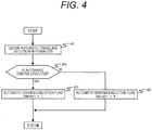
- step 301 in FIG. 3 will be described with reference to FIG. 4 .
- Step 401 is an automatic traveling execution information obtaining process. Whether or not automatic driving is executed is obtained from the automatic traveling plan device 110 by using the communication means 103. When automatic driving is executed in step 402, the flow moves to step 403, and an automatic driving execution flag fAutoDrv is set to "1". When automatic driving is not executed in step 402, the flow moves to step 404, and the automatic driving execution flag fAutoDrv is set to "0".
- automatic driving execution desirably includes that one of an accelerator operation and a brake operation is automated, and a steering operation may not be automated.
- step 303 in FIG. 3 will be described in detail with reference to FIG. 5 .
- Step 501 is an automatic traveling plan information obtaining process.
- the future target vehicle speed and target driving force, and the road gradient detected or estimated from the map information by the automatic traveling plan device 110, and the distances to the vehicles in the surroundings detected by the camera or the radar are obtained via the communication means 103.
- the future target vehicle speed and target driving force, and the road gradient are desirably plan information or prediction information of several ms ahead from a current time.
- Step 502 is a process of comparing an absolute value of a driving force plan and a predetermined value 1.
- the driving force plan value obtained in step 501 and the predetermined value 1 are compared, and, when an absolute value of the driving force plan value is smaller, i.e., when a state of a low acceleration or deceleration continues, the flow moves to step 503.
- the absolute value of the driving force plan value is larger, the flow moves to step 507, and the preshift execution flag fPRESFT is set to "1".
- the predetermined value 1 is desirably set based on a vehicle speed and an actual gear position, is desirably set to a smaller value as the vehicle speed becomes higher, and is desirably set to a smaller value as the actual gear position becomes a higher gear (toward the sixth gear).
- Step 503 is a process of comparing an absolute value of a gradient plan value and a predetermined value 2.
- the gradient plan value obtained in step 501 and the predetermined value 2 are compared and, when an absolute value of the gradient plan value is smaller, i.e., when a flat road continues, the flow moves to step 504.
- the absolute value of the gradient plan value is larger, the flow moves to step 507, and the preshift execution flag fPRESFT is set to "1".
- the predetermined value 2 is desirably set based on an actual gear position, and is desirably set to a smaller value as the actual gear position becomes a higher gear (toward the sixth gear).
- Step 504 is a process of comparing an inter-vehicle distance plan value and a predetermined value 3.
- the inter-vehicle distance plan value obtained in step 501 and the predetermined value 3 are compared and, when the inter-vehicle distance plan value is larger, i.e., when the inter-vehicle distances to the vehicles in the surroundings are distant, the flow moves to step 505.
- the flow moves to step 507, and the preshift execution flag fPRESFT is set to "1".
- the predetermined value 3 is desirably set based on a vehicle speed and an actual gear position, is desirably set to a larger value as the vehicle speed becomes higher, and is desirably set to a larger value as the actual gear position becomes a higher gear (toward the sixth gear).
- Step 505 is a process of searching a map illustrated in FIG. 9 from the vehicle speed plan value and the driving force plan value obtained in step 501 and deciding a map search result.
- a map search result indicates "cancel”
- the flow moves to step 506, and the preshift execution flag fPRESFT is set to "0".
- the map search result indicates "execute”
- the flow moves to step 507, and the preshift execution flag fPRESFT is set to "1".
- the map in FIG. 9 is desirably configured to be able to set a range for executing or canceling preshift based on the vehicle speed plan value and the driving force plan value, and can be set per actual gear position.
- FIG. 10 is a time chart during the execution of the preshift control to the down side according to the control method of the present embodiment.
- automatic driving execution fAutoDrv is in a state of "0" and indicates a manual traveling state where the driver operates the accelerator or the brake, and indicates a state where a preshift gear position is engaged with the "fourth gear” by existing preshift control.
- the driving force plan value starts increasing, and the driving force plan value exceeds the predetermined value 2 at a time t3, the preshift execution flag fPRESFT is set to "1", the preshift gear position is set to the “second gear” according to existing preshift control, and the sleeve 3 position RPslv3 is engaged with the "second gear”.
- the predetermined value 2 is re-calculated according to the actual gear position and increases, and the driving force plan value becomes smaller than the predetermined value 2. Therefore, the preshift execution flag fPRESFT is set to "0" again, the preshift gear position is set to "N” and the sleeve 2 position RPslv2 moves to "N".
- the preshift gear position moves to "N” during the gearshift (while the clutch is shifted), the driving force changes since there is no gearshift load resistance. Therefore, the preshift gear position is desirably set to "N" when the gearshift is finished.
- automatic driving execution fAutoDrv is in a state of "0" and indicates the manual traveling state where the driver operates the accelerator or the brake, and indicates a state where a preshift gear position is engaged with the "third gear” by existing preshift control.
- the preshift execution flag fPRESFT is set to "1"
- the preshift gear position is set to the "third gear” according to existing preshift control
- the sleeve 2 position RPslv2 is engaged with the "third gear”.
- the map illustrated in FIG. 9 is re-calculated according to the actual gear position.
- the preshift execution flag fPRESFT is set to "0"
- the preshift gear position is moved to "N”
- the sleeve 3 position RPslv3 moves from the "second gear” to "N".
- the preshift gear position moves to "N” during the gearshift (while the clutch is shifted), the driving force changes since there is no gearshift load resistance. Therefore, the preshift gear position is desirably set to "N" when the gearshift is finished.
Landscapes
- Engineering & Computer Science (AREA)
- General Engineering & Computer Science (AREA)
- Mechanical Engineering (AREA)
- Control Of Transmission Device (AREA)
Description
- The present invention relates to a gearshift control device.
- In recent years, as a system which automates an operation of clutches which are friction mechanisms and an operation of synchronous mesh mechanisms which are mesh mechanisms by using a gear transmission used for a manual transmission, an automated manual transmission (referred to as an "automated MT" below) has been developed. According to the automated MT, when gearshift starts, a clutch which transmits or blocks a torque of an engine which is a driving force source is disengaged, the synchronous mesh mechanisms are switched, and then the clutch is engaged again.
- Furthermore,
JP 2007-232047 A -
PTL 2 discloses a method of shift control for an automatic transmission of vehicle power train, having a permanent brake between a drive motor and a final drive, in which current vehicle-specific, road-specific and driver-specific operating parameters, topographical data relating to an upcoming stretch of road ahead of the vehicle are determined while driving, and from which a tractive resistance value for the upcoming stretch of road is determined, and control commands for thrust down-shifts and/or upshifts are derived and implemented, within the transmission, during a thrust operation depending upon the tractive resistance value. -
PTL 3 discloses a vehicular control apparatus for a vehicle comprising a twin clutch type automatic transmission. - PTL 4 discloses an automatic driving system for a vehicle includes an external sensor and an electronic control unit. The electronic control unit is configured to estimate whether the vehicle peripheral information detected by the external sensor allows the vehicle to keep a vehicle target speed set on the basis of a vehicle travel plan or temporarily does not allow the vehicle to keep the vehicle target speed.
-
- PTL 1:
JP 2007-232047 A - PTL 2:
US 9 085 293 B2 - PTL 3:
US 2016/349751 A1 - PTL 4:
EP 2 151 609 A1 - Preshift control disclosed in
PTL 1 is control of detecting a current traveling gear position, and selecting an upshift side gear position or a downshift side gear position neighbor to the current traveling gear position. - However, according to preshift, to achieve the current gearshift position, a transmission input shaft and a transmission output shaft coupled with a clutch which is not used are selectively coupled by the synchronous mesh mechanisms. Therefore, the coupling with the synchronous mesh mechanism increases an inertia mass to be applied to the transmission output shaft and produces a load, and therefore fuel efficiency is likely to worsen.
- It is therefore an object of the present invention to provide a gearshift control device which can reduce a transmission load due to preshift, and improve fuel efficiency of a vehicle during automatic driving of said vehicle, comprising a twin clutch transmission.
- According to the present invention, the aforementioned problem is solved by a gearshift control device according to
claim 1. Preferred embodiments of the present invention are laid down in the dependent claims. - According to the present invention, it is possible to reduce a transmission load due to preshift, and improve fuel efficiency of a vehicle.
-
- [
FIG. 1] FIG. 1 is a skeleton diagram illustrating a configuration of a control device of an automatic transmission according to one embodiment of the present invention. - [
FIG. 2] FIG. 2 is a block diagram illustrating an input/output signal relationship between apowertrain control unit 100 which is used for the control device of the automatic transmission according to the one embodiment of the present invention, and anengine control unit 101 and atraveling plan device 110. - [
FIG. 3] FIG. 3 is a flowchart illustrating an outline of overall control contents of a control method according to the one embodiment of the present invention. - [
FIG. 4] FIG. 4 is a flowchart illustrating an outline of automatic driving execution decision according to the one embodiment of the present invention. - [
FIG. 5] FIG. 5 is a flowchart illustrating an outline of automatic driving execution decision according to the one embodiment of the present invention. - [
FIG. 6] FIG. 6 illustrates a map illustrating settings of a threshold of a driving force plan value according to the one embodiment of the present invention. - [
FIG. 7] FIG. 7 illustrates a map illustrating settings of a threshold of a gradient plan value according to the one embodiment of the present invention. - [
FIG. 8] FIG. 8 illustrates a map illustrating settings of a threshold of an inter-vehicle distance plan value according to the one embodiment of the present invention. - [
FIG. 9] FIG. 9 illustrates a map illustrating settings of a driving range of preshift execution and cancellation according to the one embodiment of the present invention. - [
FIG. 10] FIG. 10 is a time chart illustrating a preshift operation during downshift according to the one embodiment of the present invention. - [
FIG. 11] FIG. 11 is a time chart illustrating a preshift operation during upshift according to the one embodiment of the present invention. - An embodiment of the present invention will be described in detail below with reference to
FIGS. 1 to 11 . The present embodiment relates to a control device and a control method of an automatic transmission. More particularly, the present invention relates to the control device and the control method of the automatic transmission which suitably control a gear transmission used for a car. - First, to quickly meet a gearshift request of a driver, a twin clutch automated MT executes preshift of engaging the other (clutch disengage shaft) during traveling using one of an even-numbered shaft or an odd-numbered shaft.
- However, the preshift makes a non-driven shaft a traveling resistance, and therefore is likely to deteriorate fuel efficiency.
- In view of this, a configuration example of the control device of the car including the automatic transmission according to the present invention will be described first with reference to
FIG. 1 . -
FIG. 1 is a skeleton diagram of a system configuration example illustrating one embodiment of the control device (gearshift control device) of the car including an automatic transmission according to the present invention. - An
engine 7 which is a driving force source, an engine rotational speed sensor (not illustrated) which measures a rotational speed of theengine 7, an electronic control throttle (not illustrated) which adjusts an engine torque, and a fuel injection device (not illustrated) which injects a fuel amount matching an intake air amount are provided. Anengine control unit 101 manipulates the intake air amount, the fuel amount and an ignition timing, so that it is possible to precisely control a torque of theengine 7. - The above-described fuel injection device is an intake port injection system which injects a fuel to an intake port or a cylinder injection system which directly injects the fuel in a cylinder. It is advantageous to use an engine adopting a system which can reduce fuel consumption compared to a driving range (a range determined by an engine torque and an engine rotational speed) requested for the engine, and has good exhaust capability. The driving force source may be not only a gasoline engine but also a diesel engine, a natural gas engine and an electric motor.
- An automatic transmission (transmission) 50 includes a
first clutch 8, asecond clutch 9, afirst input shaft 41, asecond input shaft 42, anoutput shaft 43, afirst drive gear 1, asecond drive gear 2, a reverse drive gear 10, athird drive gear 3, afourth drive gear 4, afifth drive gear 5, asixth drive gear 6, a first drivengear 11, a second drivengear 12, a reverse drivengear 20, a third drivengear 13, a fourth drivengear 14, a fifth drivengear 15, a sixth drivengear 16, anidler gear 30, a first synchronous mesh mechanism 21, a secondsynchronous mesh mechanism 22, a thirdsynchronous mesh mechanism 23, a fourthsynchronous mesh mechanism 24, arotation sensor 31, arotation sensor 32 and arotation sensor 33. - By engaging and disengaging the
first clutch 8, it is possible to transmit or block a torque of theengine 7 to thefirst input shaft 41. Furthermore, by engaging and disengaging thesecond clutch 9, it is possible to transmit or block the torque of theengine 7 to thesecond input shaft 42. - Multiplate wet clutches are used for the
first clutch 8 and thesecond clutch 9 in the present embodiment. However, dry single plate clutches may be used for thefirst clutch 8 and thesecond clutch 9, and all friction transmission mechanisms can be used. - Furthermore, the
first clutch 8 and thesecond clutch 9 can be also composed of electromagnetic powder clutches. - The
second input shaft 42 is hollow, and thefirst input shaft 41 penetrates the hollow portion of thesecond input shaft 42, and is configured to be able to make a relative motion in a rotation direction with respect to thesecond input shaft 42. - The
first drive gear 1, thethird drive gear 3, thefifth drive gear 5 and the reverse drive gear 10 are fixed to thesecond input shaft 42, so that thesecond input shaft 42 is rotatable with respect to thefirst input shaft 41. Furthermore, thesecond drive gear 2, thefourth drive gear 4 and thesixth drive gear 6 are fixed to thefirst input shaft 41, so that thefirst input shaft 41 is configured to be able to make a relative motion in the rotation direction with respect to thesecond input shaft 42. - The
sensor 31 is provided as means for detecting a rotational speed of thefirst input shaft 41, and thesensor 32 is provided as means for detecting a rotational speed of thesecond input shaft 42. - On the other hand, the
output shaft 43 includes the first drivengear 11, the second drivengear 12, the third drivengear 13, the fourth drivengear 14, the fifth drivengear 15, the sixth drivengear 16 and a reverse driven gear (not illustrated). The first drivengear 11, the second drivengear 12, the third drivengear 13, the fourth drivengear 14, the fifth drivengear 15, the sixth drivengear 16 and the reverse drivengear 20 are rotatably provided to theoutput shaft 43. - Furthermore, the
sensor 33 is provided as means for detecting a rotational speed of theoutput shaft 43. - Among these gears, the
first drive gear 1 and the first drivengear 11, and thesecond drive gear 2 and the second drivengear 12 mesh with each other. Furthermore, thethird drive gear 3 and the third drivengear 13, and thefourth drive gear 4 and the fourth drivengear 14 mesh with each other. Furthermore, thefifth drive gear 5 and the fifth drivengear 15, and thesixth drive gear 6 and the sixth drivengear 16 mesh with each other. Furthermore, the reverse drive gear 10, theidler gear 30 and the reverse drivengear 20 engage with each other. - Furthermore, the first synchronous mesh mechanism 21 which engages the first driven
gear 11 with theoutput shaft 43, and engages the reverse drivengear 20 with theoutput shaft 43 is provided between the first drivengear 11 and the reverse drivengear 20. - Furthermore, the third
synchronous mesh mechanism 23 which engages the second drivengear 12 with theoutput shaft 43, and engages the fourth drivengear 14 with theoutput shaft 43 is provided between the second drivengear 12 and the fourth drivengear 14. - Furthermore, the second
synchronous mesh mechanism 22 which engages the fifth drivengear 15 with theoutput shaft 43, and engages the third drivengear 13 with theoutput shaft 43 is provided between the fifth drivengear 15 and the third drivengear 13. - Furthermore, the fourth
synchronous mesh mechanism 24 which engages the sixth drivengear 16 with theoutput shaft 43 is provided to the sixth drivengear 16. - A
powertrain control unit 100 controls currents of asolenoid valve 105c and asolenoid valve 105d provided to ahydraulic mechanism 105 to control a position or a load of the first synchronous mesh mechanism 21 via a hydraulic piston (not illustrated) and a shift fork (not illustrated) provided in ashift actuator 61, and engage the first drivengear 11 or the reverse drivengear 20, so that it is possible to transmit a rotation torque of thesecond input shaft 42 to theoutput shaft 43 via the first synchronous mesh mechanism 21. In this regard, there is employed a configuration where, when the current of thesolenoid valve 105d increases, a load is applied in a direction in which the first synchronous mesh mechanism 21 moves toward the first drivengear 11, and when the current of thesolenoid valve 105c increases, a load is applied in a direction in which the first synchronous mesh mechanism 21 moves toward the reverse drivengear 20. In addition, theshift actuator 61 includes aposition sensor 61a (not illustrated) which measures the position of the first synchronous mesh mechanism 21. - Furthermore, the
powertrain control unit 100 controls currents of asolenoid valve 105e and asolenoid valve 105f provided to thehydraulic mechanism 105 to control a position or a load of the secondsynchronous mesh mechanism 22 via a hydraulic piston (not illustrated) and a shift fork (not illustrated) provided in ashift actuator 62, and engage the fifth drivengear 15 or the third drivengear 13, so that it is possible to transmit a rotation torque of thesecond input shaft 42 to theoutput shaft 43 via the secondsynchronous mesh mechanism 22. In addition, theshift actuator 62 includes aposition sensor 62a (not illustrated) which measures the position of the secondsynchronous mesh mechanism 22. - Furthermore, the
powertrain control unit 100 controls currents of asolenoid valve 105g and asolenoid valve 105h provided to thehydraulic mechanism 105 to control a position or a load of the thirdsynchronous mesh mechanism 23 via a hydraulic piston (not illustrated) and a shift fork (not illustrated) provided in ashift actuator 63, and engage the second drivengear 12 or the fourth drivengear 14, so that it is possible to transmit the rotation torque of thefirst input shaft 41 to theoutput shaft 43 via the thirdsynchronous mesh mechanism 23. In addition, theshift actuator 63 includes aposition sensor 63a (not illustrated) which measures the position of the thirdsynchronous mesh mechanism 23. - Furthermore, the
powertrain control unit 100 controls currents of asolenoid valve 105i and asolenoid valve 105j provided to thehydraulic mechanism 105 to control a position or a load of the fourthsynchronous mesh mechanism 24 via a hydraulic piston (not illustrated) and a shift fork (not illustrated) provided in ashift actuator 64, and engage the sixth drivengear 16, so that it is possible to transmit the rotation torque of thefirst input shaft 41 to theoutput shaft 43 via the fourthsynchronous mesh mechanism 24. In addition, theshift actuator 64 includes aposition sensor 64a (not illustrated) which measures the position of the fourthsynchronous mesh mechanism 24. - The rotation torque of the
transmission input shaft 41 transmitted from thefirst drive gear 1, thesecond drive gear 2, thethird drive gear 3, thefourth drive gear 4, thefifth drive gear 5, thesixth drive gear 6 and the reverse drive gear 10 to thetransmission output shaft 43 via the first drivengear 11, the second drivengear 12, the third drivengear 13, the fourth drivengear 14, the fifth drivengear 15, the sixth drivengear 16 and the reverse drivengear 20 is transmitted to an axle (not illustrated) via a differential gear (not illustrated) coupled to thetransmission output shaft 43. - Furthermore, the
powertrain control unit 100 controls a current of asolenoid valve 105a provided to thehydraulic mechanism 105 to control a pressure plate (not illustrated) provided in thefirst clutch 8 and control a transmission torque of thefirst clutch 8. - Furthermore, the
powertrain control unit 100 controls a current of asolenoid valve 105b provided to thehydraulic mechanism 105 to control a pressure plate (not illustrated) provided in thesecond clutch 9 and control a transmission torque of thesecond clutch 9. - An automatic
traveling plan device 110 is connected with a camera which can capture images of a front side, a rear side and lateral sides of a vehicle, and can recognize external environment by image processing, and detect obstacles around the vehicle or detect distances to cars driving ahead. Furthermore, the automatictraveling plan device 110 is connected with a navigation system (not illustrated) which can detect the position of the vehicle to detect the position of the own vehicle by an azimuth sensor, a GPS sensor, a vehicle speed sensor and a steering angle sensor, and read various pieces of map information such as a traveling route to a destination and a road gradient stored in the navigation system, and calculate a traveling plan such as the vehicle speed and a driving force. - The
powertrain control unit 100, theengine control unit 101 and the automatictraveling plan device 110 are configured to be able to transmit and receive information to and from each other via communication means 103. - The
solenoid valve 105c and thesolenoid valve 105d control theshift actuator 61 to mesh the first synchronous mesh mechanism 21 and the first drivengear 11, and engage thesecond clutch 9 to achieve first gear traveling. - The
solenoid valve 105g and thesolenoid valve 105h control theshift actuator 63 to mesh the thirdsynchronous mesh mechanism 23 and the second drivengear 12, and engage thefirst clutch 8 to achieve second gear traveling. - The
solenoid valve 105e and thesolenoid valve 105f control theshift actuator 62 to mesh the secondsynchronous mesh mechanism 22 and the third drivengear 13, and engage thesecond clutch 9 to achieve third gear traveling. - The
solenoid valve 105g and thesolenoid valve 105h control theshift actuator 63 to mesh the thirdsynchronous mesh mechanism 23 and the fourth drivengear 14, and engage thefirst clutch 8 to achieve fourth gear traveling. - The
solenoid valve 105e and thesolenoid valve 105f control theshift actuator 62 to mesh the secondsynchronous mesh mechanism 22 and the fifth drivengear 15, and engage thesecond clutch 9 to achieve fifth gear traveling. - The
solenoid valve 105i and thesolenoid valve 105j control theshift actuator 64 to mesh the fourthsynchronous mesh mechanism 24 and the sixth drivengear 16, and engage thefirst clutch 8 to achieve sixth gear traveling. - The
solenoid valve 105c and thesolenoid valve 105d control theshift actuator 61 to mesh the first synchronous mesh mechanism 21 and the reverse drivengear 20, and engage thesecond clutch 9 to achieve reverse gear traveling. - In addition, as a mechanism which operates the first mesh transmission mechanism 21, the second
mesh transmission mechanism 22, the thirdmesh transmission mechanism 23 and the fourthmesh transmission mechanism 24, the hydraulic mechanism which uses the solenoid valves and the hydraulic pistons is formed in the present embodiment. However, the mechanism may be formed by using electric motors and reduction gears instead of the solenoid valves and the hydraulic pistons, may be formed by using electric motors and drums, or may be formed by using other mechanisms which control themesh transmission mechanisms - Furthermore, the hydraulic mechanism which uses the solenoid valves is formed in the present embodiment to operate the
first clutch 8 and thesecond clutch 9. However, the clutches may be configured to operate by using the electronic motor and the reduction gear. An electromagnetic coil may be configured to control the pressure plates of the clutches. This configuration is also possible by using other mechanisms which control thefirst clutch 8 and thesecond clutch 9. -
FIG. 2 illustrates an input/output signal relationship between thepowertrain control unit 100, theengine control unit 101 and the automatictraveling plan device 110. Thepowertrain control unit 100 is configured as a control unit which includes an input unit 100i, an output unit 100o and acomputer 100c. Similarly, theengine control unit 101 is also configured as a control unit which includes an input unit 101i, an output unit 101o and acomputer 101c. Similarly, the automatictraveling plan device 110 is also configured as a control unit which includes an input unit 110i, an output unit 110o and acomputer 110c. - The
powertrain control unit 100 transmits an engine torque command value TTe to theengine control unit 101 by using the communication means 103, and theengine control unit 101 controls an intake air amount, a fuel amount and an ignition period (not illustrated) of theengine 7 to realize TTe. Furthermore, detecting means (not illustrated) which detects an engine torque which is an input torque to the transmission is provided in theengine control unit 101. Theengine control unit 101 detects a rotational speed Ne of theengine 7 and an engine torque Te generated by theengine 7 to transmit to thetransmission control unit 100 by using the communication means 103. The engine torque detecting means may be estimating means which estimates whether or not a torque sensor is used, or may use a parameter of the engine such as an injection pulse width of an injector, a pressure in an intake pipe and an engine rotational speed. - To realize a desired first clutch transmission torque, the
powertrain control unit 100 adjusts a voltage V_cla to be applied to thesolenoid valve 105a, thereby controls the current of thesolenoid valve 105a, and engages or disengages thefirst clutch 8. - Furthermore, to realize a desired second clutch transmission torque, the
powertrain control unit 100 adjusts a voltage V_clb to be applied to thesolenoid valve 105b, thereby controls the current of thesolenoid valve 105b, and engages or disengages thesecond clutch 9. - Furthermore, to realize a desired position of the first synchronous mesh mechanism 21, the
powertrain control unit 100 adjusts voltages V1_slv1 and V2_slv1 to be applied to thesolenoid valves solenoid valves - Furthermore, to realize a desired position of the second
synchronous mesh mechanism 22, thepowertrain control unit 100 adjusts voltages V1_slv2 and V2_slv2 to be applied to thesolenoid valves solenoid valves synchronous mesh mechanism 22. - Furthermore, to realize a desired position of the third
synchronous mesh mechanism 23, thepowertrain control unit 100 adjusts voltages V1_slv3 and V2-slv3 to be applied to thesolenoid valves solenoid valves synchronous mesh mechanism 23. - Furthermore, to realize a desired position of the fourth
synchronous mesh mechanism 24, thepowertrain control unit 100 adjusts voltages V1_slv4 and V2_slv4 to be applied to thesolenoid valves solenoid valves synchronous mesh mechanism 24. - In addition, the
powertrain control unit 100 includes a current detection circuit (not illustrated), and changes a voltage output such that the current of each solenoid valve follows a target current and controls the current of each solenoid valve. - Furthermore, the
powertrain control unit 100 receives an input of a first input shaft rotational speed NiA, a second input shaft rotational speed NiB and an output shaft rotational speed No from therotation sensor 31, therotation sensor 32 and therotation sensor 33. - Furthermore, the
powertrain control unit 100 receives an input of an accelerator pedal step-on amount Aps from anaccelerator position sensor 302. - Furthermore, the
powertrain control unit 100 receives an input of an ON/OFF signal Brk for detecting whether or not a brake is stepped on from abrake switch 304. - Furthermore, the
powertrain control unit 100 receives an input of asleeve 1 position RPslv1, asleeve 2 position RPslv2, asleeve 3 position RPslv3 and asleeve 4 position RPslv4 which indicate respective stroke positions of the first synchronous mesh mechanism 21, the secondsynchronous mesh mechanism 22, the thirdsynchronous mesh mechanism 23 and the fourthsynchronous mesh mechanism 24 from thesleeve 1position sensor 61a, thesleeve 2position sensor 62a, thesleeve 3position sensor 63a and thesleeve 4position sensor 64a. - Furthermore, the
powertrain control unit 100 receives an input of a clutch Ahydraulic sensor 65 which can detect an oil pressure Pcla of thefirst clutch 8, and a clutch Bhydraulic sensor 66 which can detect an oil pressure Pclb of thesecond clutch 9. - The automatic
traveling plan device 110 transmits an automatic driving execution/non-execution state fAutoDrv to thepowertrain control unit 100 by using the communication means 103. Furthermore, the automatictraveling plan device 110 transmits a future target vehicle speed and target driving force, and a road gradient detected or estimated from the map information to thepowertrain control unit 100 by using the communication means 103. Furthermore, the automatictraveling plan device 110 transmits distances to vehicles in the surroundings detected by a camera or a radar to thepowertrain control unit 100 by using the communication means 103. - Next, a control method of the control device of the automatic transmission according to the present embodiment will be described with reference to
FIGS. 3 to 9 . -
FIG. 3 is a flowchart illustrating an outline of overall control contents of the control method of the automatic transmission according to the first embodiment of the present invention. - Contents in
FIG. 3 is programmed to thecomputer 100c of thepowertrain control unit 100, and is repeatedly executed at a predetermined cycle. That is, processing in followingsteps 301 to 306 is executed by thepowertrain control unit 100. - Step 301 is an automatic driving execution deciding process. Whether or not to execute automatic traveling is computed by using information received from the automatic
traveling plan device 110 by using the communication means 103 to decide whether or not to execute automatic traveling instep 302. - When fAutoDrv is "1" in
step 302, it is decided to execute automatic driving, and the flow moves to step 303. When fAutoDrv is "0", it is decided not to execute automatic driving, and the flow moves to step 306 to execute existing manual driving preshift control. - Step 303 is an automatic driving preshift execution decision computing process, and computes preshift execution during automatic driving based on a driving force plan value or gradient information. In addition, this process is performed by an automatic driving preshift execution deciding unit (not illustrated).
- Step 304 is an automatic driving preshift execution deciding process which uses a computation result in
step 303. In addition, this process is performed by an automatic driving preshift execution deciding unit (not illustrated). When fPRESFT is "0", it is decided to cancel automatic driving preshift, and the flow moves to step 305. When fPRESFT is "1", it is decided to execute automatic driving preshift, and the flow moves to step 306 to execute existing manual driving preshift control. - Next, details of
step 301 inFIG. 3 will be described with reference toFIG. 4 . - Step 401 is an automatic traveling execution information obtaining process. Whether or not automatic driving is executed is obtained from the automatic
traveling plan device 110 by using the communication means 103. When automatic driving is executed instep 402, the flow moves to step 403, and an automatic driving execution flag fAutoDrv is set to "1". When automatic driving is not executed instep 402, the flow moves to step 404, and the automatic driving execution flag fAutoDrv is set to "0". - In this regard, automatic driving execution desirably includes that one of an accelerator operation and a brake operation is automated, and a steering operation may not be automated.
- Next, details of
step 303 inFIG. 3 will be described in detail with reference toFIG. 5 . - Step 501 is an automatic traveling plan information obtaining process. The future target vehicle speed and target driving force, and the road gradient detected or estimated from the map information by the automatic
traveling plan device 110, and the distances to the vehicles in the surroundings detected by the camera or the radar are obtained via the communication means 103. - In this regard, the future target vehicle speed and target driving force, and the road gradient are desirably plan information or prediction information of several ms ahead from a current time.
- Step 502 is a process of comparing an absolute value of a driving force plan and a
predetermined value 1. The driving force plan value obtained instep 501 and thepredetermined value 1 are compared, and, when an absolute value of the driving force plan value is smaller, i.e., when a state of a low acceleration or deceleration continues, the flow moves to step 503. When the absolute value of the driving force plan value is larger, the flow moves to step 507, and the preshift execution flag fPRESFT is set to "1". - In this regard, as illustrated in
FIG. 6 , thepredetermined value 1 is desirably set based on a vehicle speed and an actual gear position, is desirably set to a smaller value as the vehicle speed becomes higher, and is desirably set to a smaller value as the actual gear position becomes a higher gear (toward the sixth gear). - Step 503 is a process of comparing an absolute value of a gradient plan value and a
predetermined value 2. The gradient plan value obtained instep 501 and thepredetermined value 2 are compared and, when an absolute value of the gradient plan value is smaller, i.e., when a flat road continues, the flow moves to step 504. When the absolute value of the gradient plan value is larger, the flow moves to step 507, and the preshift execution flag fPRESFT is set to "1". - In this regard, as illustrated in
FIG. 7 , thepredetermined value 2 is desirably set based on an actual gear position, and is desirably set to a smaller value as the actual gear position becomes a higher gear (toward the sixth gear). - Step 504 is a process of comparing an inter-vehicle distance plan value and a
predetermined value 3. The inter-vehicle distance plan value obtained instep 501 and thepredetermined value 3 are compared and, when the inter-vehicle distance plan value is larger, i.e., when the inter-vehicle distances to the vehicles in the surroundings are distant, the flow moves to step 505. When the inter-vehicle distance plan value is larger, the flow moves to step 507, and the preshift execution flag fPRESFT is set to "1". - In this regard, as illustrated in
FIG. 8 , thepredetermined value 3 is desirably set based on a vehicle speed and an actual gear position, is desirably set to a larger value as the vehicle speed becomes higher, and is desirably set to a larger value as the actual gear position becomes a higher gear (toward the sixth gear). - Step 505 is a process of searching a map illustrated in
FIG. 9 from the vehicle speed plan value and the driving force plan value obtained instep 501 and deciding a map search result. When a map search result indicates "cancel", the flow moves to step 506, and the preshift execution flag fPRESFT is set to "0". When the map search result indicates "execute", the flow moves to step 507, and the preshift execution flag fPRESFT is set to "1". - The map in
FIG. 9 is desirably configured to be able to set a range for executing or canceling preshift based on the vehicle speed plan value and the driving force plan value, and can be set per actual gear position. - By employing the above configuration, it is possible to detect based on a traveling plan such as the driving force plan value and the inter-vehicle distance plan value that the state of the low acceleration or deceleration continues, the flat road continues or the state of the distant inter-vehicle distances continues, and cancel preshift. Furthermore, it is possible to search an acceleration/deceleration increase plan, a climb plan or a plan which decreases the inter-vehicle distances from the traveling plan such as the driving force plan value and the inter-vehicle distance plan value, and execute preshift.
- Next, an operation during execution of preshift control to a down side in the control device of the automatic transmission according to the control method of the present embodiment will be described with reference to
FIG. 10 . -
FIG. 10 is a time chart during the execution of the preshift control to the down side according to the control method of the present embodiment. - Before a time t1, automatic driving execution fAutoDrv is in a state of "0" and indicates a manual traveling state where the driver operates the accelerator or the brake, and indicates a state where a preshift gear position is engaged with the "fourth gear" by existing preshift control.
- When automatic driving execution fAutoDrv is set to "1" at the time t1, the accelerator or brake operation is automated, the driving force plan value is smaller than the
predetermined value 2. Therefore, the preshift execution flag fPRESFT is set to "0", the preshift gear position is set to "N", and then thesleeve 3 position RPslv3 moves from the "fourth gear" to "N". - When an increase in the future actual driving force is detected at a time t2, the driving force plan value starts increasing, and the driving force plan value exceeds the
predetermined value 2 at a time t3, the preshift execution flag fPRESFT is set to "1", the preshift gear position is set to the "second gear" according to existing preshift control, and thesleeve 3 position RPslv3 is engaged with the "second gear". - At a time t4, when an actual driving force increases, downshift is executed, and a target gear position is set to the "second gear" to execute gearshift.
- When it is decided that the gearshift is finished at a time t5, the
predetermined value 2 is re-calculated according to the actual gear position and increases, and the driving force plan value becomes smaller than thepredetermined value 2. Therefore, the preshift execution flag fPRESFT is set to "0" again, the preshift gear position is set to "N" and thesleeve 2 position RPslv2 moves to "N". - When the preshift gear position moves to "N" during the gearshift (while the clutch is shifted), the driving force changes since there is no gearshift load resistance. Therefore, the preshift gear position is desirably set to "N" when the gearshift is finished.
- Next, an operation during execution of preshift control to an up side in the control device of the automatic transmission according to the control method of the present embodiment will be described with reference to
FIG. 11 . - Before the time t1, automatic driving execution fAutoDrv is in a state of "0" and indicates the manual traveling state where the driver operates the accelerator or the brake, and indicates a state where a preshift gear position is engaged with the "third gear" by existing preshift control.
- When automatic driving execution fAutoDrv is set to "1" at the time t1, the accelerator or brake operation is automated. When the map illustrated in
FIG. 9 is searched from the vehicle speed plan value and the driving force plan value, and the range is decided as the preshift cancellation range, the preshift execution flag fPRESFT is set to "0", the preshift gear position is set to "N", and then thesleeve 2 position RPslv2 moves from the "third gear" to "N". - When the map illustrated in
FIG. 9 is searched from the vehicle speed plan value and the driving force plan value at the time t2 and the range is decided as the preshift cancellation range, the preshift execution flag fPRESFT is set to "1", the preshift gear position is set to the "third gear" according to existing preshift control, and thesleeve 2 position RPslv2 is engaged with the "third gear". - At the time t3, when an actual vehicle speed increases, upshift is executed, and the target gear position is set to the "third gear" to execute gearshift.
- When it is decided that the gearshift is finished at the time t4, the map illustrated in
FIG. 9 is re-calculated according to the actual gear position. When the range is decided as the preshift cancellation range based on the vehicle speed plan value and the driving force plan value, the preshift execution flag fPRESFT is set to "0", the preshift gear position is moved to "N", and then thesleeve 3 position RPslv3 moves from the "second gear" to "N". - When the preshift gear position moves to "N" during the gearshift (while the clutch is shifted), the driving force changes since there is no gearshift load resistance. Therefore, the preshift gear position is desirably set to "N" when the gearshift is finished.
-
- 50
- transmission (automatic transmission)
- 100
- powertrain control unit
- 101
- engine control unit
- 105
- hydraulic mechanism
- 110
- automatic traveling plan device
Claims (10)
- A gearshift control device which is configured to control a transmission (50) comprising a twin clutch transmission including two systems of power transmission mechanisms, the gearshift control device configured to preshift the transmission (50) based on a traveling plan during automatic driving of a vehicle, in which one of an accelerator operation and a brake operation is automated, and a steering operation may not be automated, comprising: an automatic driving preshift execution deciding unit which is configured to plan control contents of the transmission (50) based on the traveling plan; and
is configured to decide to cancel automatic driving preshift or to execute automatic driving preshift, represented by executing an existing manual driving preshift control. - The gearshift control device according to claim 1, configured to calculate the traveling plan such as a vehicle speed plan value and driving force plan value based on one of a navigation system, a radar, a camera and map information.
- The gearshift control device according to claim 1, wherein the traveling plan is a driving force plan value.
- The gearshift control device according to claim 1, wherein the traveling plan is a vehicle speed plan value.
- The gearshift control device according to claim 1, wherein the traveling plan is a gradient plan value.
- The gearshift control device according to claim 1, wherein the traveling plan is an inter-vehicle distance plan value.
- The gearshift control device according to claim 3, configured to execute the automatic driving preshift, when the driving force
plan value is larger than a threshold set in advance according to a gear position and a vehicle speed. - The gearshift control device according to claim 4, configured to execute the automatic driving preshift, when the vehicle speed
plan value is larger than a threshold set in advance according to a gear position. - The gearshift control device according to claim 5, configured to execute the automatic driving preshift, when the gradient plan
value is larger than a threshold set in advance according to a gear position and a vehicle speed. - The gearshift control device according to claim 6, configured to execute the automatic driving preshift, when the inter-vehicle
distance plan value is larger than a threshold set in advance according to a gear position and a vehicle speed.
Applications Claiming Priority (2)
| Application Number | Priority Date | Filing Date | Title |
|---|---|---|---|
| JP2017056812 | 2017-03-23 | ||
| PCT/JP2018/007430 WO2018173661A1 (en) | 2017-03-23 | 2018-02-28 | Transmission control device |
Publications (3)
| Publication Number | Publication Date |
|---|---|
| EP3604863A1 EP3604863A1 (en) | 2020-02-05 |
| EP3604863A4 EP3604863A4 (en) | 2020-12-30 |
| EP3604863B1 true EP3604863B1 (en) | 2022-01-12 |
Family
ID=63585148
Family Applications (1)
| Application Number | Title | Priority Date | Filing Date |
|---|---|---|---|
| EP18770282.4A Active EP3604863B1 (en) | 2017-03-23 | 2018-02-28 | Transmission control device |
Country Status (5)
| Country | Link |
|---|---|
| US (1) | US11009122B2 (en) |
| EP (1) | EP3604863B1 (en) |
| JP (1) | JPWO2018173661A1 (en) |
| CN (1) | CN110402344B (en) |
| WO (1) | WO2018173661A1 (en) |
Families Citing this family (1)
| Publication number | Priority date | Publication date | Assignee | Title |
|---|---|---|---|---|
| JP7034225B1 (en) * | 2020-09-25 | 2022-03-11 | 日立建機株式会社 | Mining machinery |
Family Cites Families (12)
| Publication number | Priority date | Publication date | Assignee | Title |
|---|---|---|---|---|
| JPH03153958A (en) * | 1989-11-09 | 1991-07-01 | Aisin Aw Co Ltd | Manual select device of automatic transmission for vehicle |
| DE10163402A1 (en) | 2001-12-21 | 2003-07-03 | Zf Sachs Ag | Motor vehicle with multiple clutch and multi-gear gearbox, has controller for detecting increased probability of down shift to lower destination gear and engaging a suitable gear |
| JP2007232047A (en) | 2006-02-28 | 2007-09-13 | Hitachi Ltd | Control apparatus and control method for automobile |
| JP4640250B2 (en) * | 2006-04-27 | 2011-03-02 | 日産自動車株式会社 | Transmission control device for twin-clutch automatic manual transmission |
| JP2009041601A (en) * | 2007-08-07 | 2009-02-26 | Hitachi Ltd | Control device and control method for automatic transmission |
| US8099220B2 (en) * | 2008-07-29 | 2012-01-17 | GM Global Technology Operations LLC | Method for adapting shift schedule of an automatic transmission based on GPS/map information |
| JP5232565B2 (en) | 2008-08-04 | 2013-07-10 | アイシン・エーアイ株式会社 | Dual clutch transmission |
| JP5445758B2 (en) | 2009-11-26 | 2014-03-19 | ダイムラー・アクチェンゲゼルシャフト | Vehicle transmission control device |
| DE102010041324A1 (en) | 2010-09-24 | 2012-03-29 | Zf Friedrichshafen Ag | Method for switching control of an automated stepped gearbox |
| DE102010042267A1 (en) * | 2010-10-11 | 2012-04-12 | Zf Friedrichshafen Ag | Method for controlling circuits of a partial dual clutch transmission |
| JP6112123B2 (en) * | 2015-01-19 | 2017-04-12 | トヨタ自動車株式会社 | Automatic driving device |
| JP6394497B2 (en) * | 2015-05-25 | 2018-09-26 | トヨタ自動車株式会社 | Automatic vehicle driving system |
-
2018
- 2018-02-28 EP EP18770282.4A patent/EP3604863B1/en active Active
- 2018-02-28 CN CN201880005585.2A patent/CN110402344B/en active Active
- 2018-02-28 JP JP2019507480A patent/JPWO2018173661A1/en active Pending
- 2018-02-28 US US16/473,447 patent/US11009122B2/en active Active
- 2018-02-28 WO PCT/JP2018/007430 patent/WO2018173661A1/en not_active Ceased
Also Published As
| Publication number | Publication date |
|---|---|
| EP3604863A4 (en) | 2020-12-30 |
| US20200141483A1 (en) | 2020-05-07 |
| JPWO2018173661A1 (en) | 2019-11-07 |
| EP3604863A1 (en) | 2020-02-05 |
| WO2018173661A1 (en) | 2018-09-27 |
| CN110402344B (en) | 2022-03-22 |
| CN110402344A (en) | 2019-11-01 |
| US11009122B2 (en) | 2021-05-18 |
Similar Documents
| Publication | Publication Date | Title |
|---|---|---|
| US9677530B2 (en) | Assisted direct start engine control for enhanced launch performance | |
| US10099702B2 (en) | Method and apparatus for vehicle accessory and load management | |
| CN109720334B (en) | Hybrid vehicle | |
| CN110608287B (en) | Vehicle control device | |
| JP2019188962A (en) | Vehicle controller | |
| US9902393B2 (en) | Vehicle control system | |
| CN110001617A (en) | The control device of vehicle | |
| EP3006698B1 (en) | Vehicle control apparatus and vehicle control method | |
| US10691124B2 (en) | Control apparatus for vehicle | |
| JP2019121063A (en) | Traveling control device for automatic driving vehicle | |
| JP2019119303A (en) | Travel control device for automatic drive vehicle | |
| CN110001642A (en) | The travel controlling system of automatic driving vehicle | |
| JP2019084917A (en) | Vehicle control device | |
| US20190031172A1 (en) | Vehicle control system | |
| CN210554769U (en) | vehicle control device | |
| US10351136B2 (en) | Method for controlling a rolling mode or a freewheel mode of a vehicle | |
| CN102806903A (en) | Rolling neutral mode control systems and methods | |
| EP3604863B1 (en) | Transmission control device | |
| WO2019244261A1 (en) | Vehicle control method and vehicle control device | |
| JP2023071549A (en) | Driving force control device | |
| CN210554767U (en) | Transmission control device | |
| US11009369B2 (en) | Method for operating a vehicle, in particular a commercial vehicle | |
| CN118478898A (en) | Train traveling system | |
| JP6622417B2 (en) | Transmission control device | |
| JP2021099152A (en) | Vehicle control device |
Legal Events
| Date | Code | Title | Description |
|---|---|---|---|
| STAA | Information on the status of an ep patent application or granted ep patent |
Free format text: STATUS: THE INTERNATIONAL PUBLICATION HAS BEEN MADE |
|
| PUAI | Public reference made under article 153(3) epc to a published international application that has entered the european phase |
Free format text: ORIGINAL CODE: 0009012 |
|
| STAA | Information on the status of an ep patent application or granted ep patent |
Free format text: STATUS: REQUEST FOR EXAMINATION WAS MADE |
|
| 17P | Request for examination filed |
Effective date: 20191023 |
|
| AK | Designated contracting states |
Kind code of ref document: A1 Designated state(s): AL AT BE BG CH CY CZ DE DK EE ES FI FR GB GR HR HU IE IS IT LI LT LU LV MC MK MT NL NO PL PT RO RS SE SI SK SM TR |
|
| AX | Request for extension of the european patent |
Extension state: BA ME |
|
| DAV | Request for validation of the european patent (deleted) | ||
| DAX | Request for extension of the european patent (deleted) | ||
| A4 | Supplementary search report drawn up and despatched |
Effective date: 20201201 |
|
| RIC1 | Information provided on ipc code assigned before grant |
Ipc: F16H 61/02 20060101AFI20201125BHEP Ipc: F16H 61/688 20060101ALI20201125BHEP |
|
| GRAP | Despatch of communication of intention to grant a patent |
Free format text: ORIGINAL CODE: EPIDOSNIGR1 |
|
| STAA | Information on the status of an ep patent application or granted ep patent |
Free format text: STATUS: GRANT OF PATENT IS INTENDED |
|
| INTG | Intention to grant announced |
Effective date: 20210811 |
|
| RAP3 | Party data changed (applicant data changed or rights of an application transferred) |
Owner name: HITACHI ASTEMO, LTD. |
|
| GRAS | Grant fee paid |
Free format text: ORIGINAL CODE: EPIDOSNIGR3 |
|
| GRAA | (expected) grant |
Free format text: ORIGINAL CODE: 0009210 |
|
| STAA | Information on the status of an ep patent application or granted ep patent |
Free format text: STATUS: THE PATENT HAS BEEN GRANTED |
|
| AK | Designated contracting states |
Kind code of ref document: B1 Designated state(s): AL AT BE BG CH CY CZ DE DK EE ES FI FR GB GR HR HU IE IS IT LI LT LU LV MC MK MT NL NO PL PT RO RS SE SI SK SM TR |
|
| REG | Reference to a national code |
Ref country code: GB Ref legal event code: FG4D |
|
| REG | Reference to a national code |
Ref country code: CH Ref legal event code: EP |
|
| REG | Reference to a national code |
Ref country code: DE Ref legal event code: R096 Ref document number: 602018029557 Country of ref document: DE |
|
| REG | Reference to a national code |
Ref country code: IE Ref legal event code: FG4D |
|
| REG | Reference to a national code |
Ref country code: AT Ref legal event code: REF Ref document number: 1462603 Country of ref document: AT Kind code of ref document: T Effective date: 20220215 |
|
| REG | Reference to a national code |
Ref country code: LT Ref legal event code: MG9D |
|
| REG | Reference to a national code |
Ref country code: NL Ref legal event code: MP Effective date: 20220112 |
|
| REG | Reference to a national code |
Ref country code: AT Ref legal event code: MK05 Ref document number: 1462603 Country of ref document: AT Kind code of ref document: T Effective date: 20220112 |
|
| PG25 | Lapsed in a contracting state [announced via postgrant information from national office to epo] |
Ref country code: NL Free format text: LAPSE BECAUSE OF FAILURE TO SUBMIT A TRANSLATION OF THE DESCRIPTION OR TO PAY THE FEE WITHIN THE PRESCRIBED TIME-LIMIT Effective date: 20220112 |
|
| PG25 | Lapsed in a contracting state [announced via postgrant information from national office to epo] |
Ref country code: SE Free format text: LAPSE BECAUSE OF FAILURE TO SUBMIT A TRANSLATION OF THE DESCRIPTION OR TO PAY THE FEE WITHIN THE PRESCRIBED TIME-LIMIT Effective date: 20220112 Ref country code: RS Free format text: LAPSE BECAUSE OF FAILURE TO SUBMIT A TRANSLATION OF THE DESCRIPTION OR TO PAY THE FEE WITHIN THE PRESCRIBED TIME-LIMIT Effective date: 20220112 Ref country code: PT Free format text: LAPSE BECAUSE OF FAILURE TO SUBMIT A TRANSLATION OF THE DESCRIPTION OR TO PAY THE FEE WITHIN THE PRESCRIBED TIME-LIMIT Effective date: 20220512 Ref country code: NO Free format text: LAPSE BECAUSE OF FAILURE TO SUBMIT A TRANSLATION OF THE DESCRIPTION OR TO PAY THE FEE WITHIN THE PRESCRIBED TIME-LIMIT Effective date: 20220412 Ref country code: LT Free format text: LAPSE BECAUSE OF FAILURE TO SUBMIT A TRANSLATION OF THE DESCRIPTION OR TO PAY THE FEE WITHIN THE PRESCRIBED TIME-LIMIT Effective date: 20220112 Ref country code: HR Free format text: LAPSE BECAUSE OF FAILURE TO SUBMIT A TRANSLATION OF THE DESCRIPTION OR TO PAY THE FEE WITHIN THE PRESCRIBED TIME-LIMIT Effective date: 20220112 Ref country code: ES Free format text: LAPSE BECAUSE OF FAILURE TO SUBMIT A TRANSLATION OF THE DESCRIPTION OR TO PAY THE FEE WITHIN THE PRESCRIBED TIME-LIMIT Effective date: 20220112 Ref country code: BG Free format text: LAPSE BECAUSE OF FAILURE TO SUBMIT A TRANSLATION OF THE DESCRIPTION OR TO PAY THE FEE WITHIN THE PRESCRIBED TIME-LIMIT Effective date: 20220412 |
|
| PG25 | Lapsed in a contracting state [announced via postgrant information from national office to epo] |
Ref country code: PL Free format text: LAPSE BECAUSE OF FAILURE TO SUBMIT A TRANSLATION OF THE DESCRIPTION OR TO PAY THE FEE WITHIN THE PRESCRIBED TIME-LIMIT Effective date: 20220112 Ref country code: LV Free format text: LAPSE BECAUSE OF FAILURE TO SUBMIT A TRANSLATION OF THE DESCRIPTION OR TO PAY THE FEE WITHIN THE PRESCRIBED TIME-LIMIT Effective date: 20220112 Ref country code: GR Free format text: LAPSE BECAUSE OF FAILURE TO SUBMIT A TRANSLATION OF THE DESCRIPTION OR TO PAY THE FEE WITHIN THE PRESCRIBED TIME-LIMIT Effective date: 20220413 Ref country code: FI Free format text: LAPSE BECAUSE OF FAILURE TO SUBMIT A TRANSLATION OF THE DESCRIPTION OR TO PAY THE FEE WITHIN THE PRESCRIBED TIME-LIMIT Effective date: 20220112 Ref country code: AT Free format text: LAPSE BECAUSE OF FAILURE TO SUBMIT A TRANSLATION OF THE DESCRIPTION OR TO PAY THE FEE WITHIN THE PRESCRIBED TIME-LIMIT Effective date: 20220112 |
|
| PG25 | Lapsed in a contracting state [announced via postgrant information from national office to epo] |
Ref country code: IS Free format text: LAPSE BECAUSE OF FAILURE TO SUBMIT A TRANSLATION OF THE DESCRIPTION OR TO PAY THE FEE WITHIN THE PRESCRIBED TIME-LIMIT Effective date: 20220512 |
|
| REG | Reference to a national code |
Ref country code: DE Ref legal event code: R097 Ref document number: 602018029557 Country of ref document: DE |
|
| REG | Reference to a national code |
Ref country code: CH Ref legal event code: PL |
|
| REG | Reference to a national code |
Ref country code: BE Ref legal event code: MM Effective date: 20220228 |
|
| PG25 | Lapsed in a contracting state [announced via postgrant information from national office to epo] |
Ref country code: SM Free format text: LAPSE BECAUSE OF FAILURE TO SUBMIT A TRANSLATION OF THE DESCRIPTION OR TO PAY THE FEE WITHIN THE PRESCRIBED TIME-LIMIT Effective date: 20220112 Ref country code: SK Free format text: LAPSE BECAUSE OF FAILURE TO SUBMIT A TRANSLATION OF THE DESCRIPTION OR TO PAY THE FEE WITHIN THE PRESCRIBED TIME-LIMIT Effective date: 20220112 Ref country code: RO Free format text: LAPSE BECAUSE OF FAILURE TO SUBMIT A TRANSLATION OF THE DESCRIPTION OR TO PAY THE FEE WITHIN THE PRESCRIBED TIME-LIMIT Effective date: 20220112 Ref country code: MC Free format text: LAPSE BECAUSE OF FAILURE TO SUBMIT A TRANSLATION OF THE DESCRIPTION OR TO PAY THE FEE WITHIN THE PRESCRIBED TIME-LIMIT Effective date: 20220112 Ref country code: LU Free format text: LAPSE BECAUSE OF NON-PAYMENT OF DUE FEES Effective date: 20220228 Ref country code: EE Free format text: LAPSE BECAUSE OF FAILURE TO SUBMIT A TRANSLATION OF THE DESCRIPTION OR TO PAY THE FEE WITHIN THE PRESCRIBED TIME-LIMIT Effective date: 20220112 Ref country code: DK Free format text: LAPSE BECAUSE OF FAILURE TO SUBMIT A TRANSLATION OF THE DESCRIPTION OR TO PAY THE FEE WITHIN THE PRESCRIBED TIME-LIMIT Effective date: 20220112 Ref country code: CZ Free format text: LAPSE BECAUSE OF FAILURE TO SUBMIT A TRANSLATION OF THE DESCRIPTION OR TO PAY THE FEE WITHIN THE PRESCRIBED TIME-LIMIT Effective date: 20220112 |
|
| PLBE | No opposition filed within time limit |
Free format text: ORIGINAL CODE: 0009261 |
|
| STAA | Information on the status of an ep patent application or granted ep patent |
Free format text: STATUS: NO OPPOSITION FILED WITHIN TIME LIMIT |
|
| PG25 | Lapsed in a contracting state [announced via postgrant information from national office to epo] |
Ref country code: AL Free format text: LAPSE BECAUSE OF FAILURE TO SUBMIT A TRANSLATION OF THE DESCRIPTION OR TO PAY THE FEE WITHIN THE PRESCRIBED TIME-LIMIT Effective date: 20220112 |
|
| 26N | No opposition filed |
Effective date: 20221013 |
|
| GBPC | Gb: european patent ceased through non-payment of renewal fee |
Effective date: 20220412 |
|
| PG25 | Lapsed in a contracting state [announced via postgrant information from national office to epo] |
Ref country code: LI Free format text: LAPSE BECAUSE OF NON-PAYMENT OF DUE FEES Effective date: 20220228 Ref country code: IE Free format text: LAPSE BECAUSE OF NON-PAYMENT OF DUE FEES Effective date: 20220228 Ref country code: GB Free format text: LAPSE BECAUSE OF NON-PAYMENT OF DUE FEES Effective date: 20220412 Ref country code: FR Free format text: LAPSE BECAUSE OF NON-PAYMENT OF DUE FEES Effective date: 20220312 Ref country code: CH Free format text: LAPSE BECAUSE OF NON-PAYMENT OF DUE FEES Effective date: 20220228 |
|
| PG25 | Lapsed in a contracting state [announced via postgrant information from national office to epo] |
Ref country code: SI Free format text: LAPSE BECAUSE OF FAILURE TO SUBMIT A TRANSLATION OF THE DESCRIPTION OR TO PAY THE FEE WITHIN THE PRESCRIBED TIME-LIMIT Effective date: 20220112 Ref country code: BE Free format text: LAPSE BECAUSE OF NON-PAYMENT OF DUE FEES Effective date: 20220228 |
|
| PG25 | Lapsed in a contracting state [announced via postgrant information from national office to epo] |
Ref country code: IT Free format text: LAPSE BECAUSE OF FAILURE TO SUBMIT A TRANSLATION OF THE DESCRIPTION OR TO PAY THE FEE WITHIN THE PRESCRIBED TIME-LIMIT Effective date: 20220112 |
|
| PG25 | Lapsed in a contracting state [announced via postgrant information from national office to epo] |
Ref country code: MK Free format text: LAPSE BECAUSE OF FAILURE TO SUBMIT A TRANSLATION OF THE DESCRIPTION OR TO PAY THE FEE WITHIN THE PRESCRIBED TIME-LIMIT Effective date: 20220112 Ref country code: CY Free format text: LAPSE BECAUSE OF FAILURE TO SUBMIT A TRANSLATION OF THE DESCRIPTION OR TO PAY THE FEE WITHIN THE PRESCRIBED TIME-LIMIT Effective date: 20220112 |
|
| PG25 | Lapsed in a contracting state [announced via postgrant information from national office to epo] |
Ref country code: HU Free format text: LAPSE BECAUSE OF FAILURE TO SUBMIT A TRANSLATION OF THE DESCRIPTION OR TO PAY THE FEE WITHIN THE PRESCRIBED TIME-LIMIT; INVALID AB INITIO Effective date: 20180228 |
|
| PG25 | Lapsed in a contracting state [announced via postgrant information from national office to epo] |
Ref country code: MT Free format text: LAPSE BECAUSE OF FAILURE TO SUBMIT A TRANSLATION OF THE DESCRIPTION OR TO PAY THE FEE WITHIN THE PRESCRIBED TIME-LIMIT Effective date: 20220112 |
|
| PG25 | Lapsed in a contracting state [announced via postgrant information from national office to epo] |
Ref country code: TR Free format text: LAPSE BECAUSE OF FAILURE TO SUBMIT A TRANSLATION OF THE DESCRIPTION OR TO PAY THE FEE WITHIN THE PRESCRIBED TIME-LIMIT Effective date: 20220112 |
|
| PGFP | Annual fee paid to national office [announced via postgrant information from national office to epo] |
Ref country code: DE Payment date: 20260102 Year of fee payment: 9 |