EP3604812A1 - Scroll fluid machine - Google Patents
Scroll fluid machine Download PDFInfo
- Publication number
- EP3604812A1 EP3604812A1 EP18846505.8A EP18846505A EP3604812A1 EP 3604812 A1 EP3604812 A1 EP 3604812A1 EP 18846505 A EP18846505 A EP 18846505A EP 3604812 A1 EP3604812 A1 EP 3604812A1
- Authority
- EP
- European Patent Office
- Prior art keywords
- wall
- end plate
- inclined portion
- tip
- tip seal
- Prior art date
- Legal status (The legal status is an assumption and is not a legal conclusion. Google has not performed a legal analysis and makes no representation as to the accuracy of the status listed.)
- Granted
Links
Images







Classifications
-
- F—MECHANICAL ENGINEERING; LIGHTING; HEATING; WEAPONS; BLASTING
- F04—POSITIVE - DISPLACEMENT MACHINES FOR LIQUIDS; PUMPS FOR LIQUIDS OR ELASTIC FLUIDS
- F04C—ROTARY-PISTON, OR OSCILLATING-PISTON, POSITIVE-DISPLACEMENT MACHINES FOR LIQUIDS; ROTARY-PISTON, OR OSCILLATING-PISTON, POSITIVE-DISPLACEMENT PUMPS
- F04C18/00—Rotary-piston pumps specially adapted for elastic fluids
- F04C18/02—Rotary-piston pumps specially adapted for elastic fluids of arcuate-engagement type, i.e. with circular translatory movement of co-operating members, each member having the same number of teeth or tooth-equivalents
- F04C18/0207—Rotary-piston pumps specially adapted for elastic fluids of arcuate-engagement type, i.e. with circular translatory movement of co-operating members, each member having the same number of teeth or tooth-equivalents both members having co-operating elements in spiral form
- F04C18/0215—Rotary-piston pumps specially adapted for elastic fluids of arcuate-engagement type, i.e. with circular translatory movement of co-operating members, each member having the same number of teeth or tooth-equivalents both members having co-operating elements in spiral form where only one member is moving
-
- F—MECHANICAL ENGINEERING; LIGHTING; HEATING; WEAPONS; BLASTING
- F01—MACHINES OR ENGINES IN GENERAL; ENGINE PLANTS IN GENERAL; STEAM ENGINES
- F01C—ROTARY-PISTON OR OSCILLATING-PISTON MACHINES OR ENGINES
- F01C1/00—Rotary-piston machines or engines
- F01C1/02—Rotary-piston machines or engines of arcuate-engagement type, i.e. with circular translatory movement of co-operating members, each member having the same number of teeth or tooth-equivalents
-
- F—MECHANICAL ENGINEERING; LIGHTING; HEATING; WEAPONS; BLASTING
- F01—MACHINES OR ENGINES IN GENERAL; ENGINE PLANTS IN GENERAL; STEAM ENGINES
- F01C—ROTARY-PISTON OR OSCILLATING-PISTON MACHINES OR ENGINES
- F01C19/00—Sealing arrangements in rotary-piston machines or engines
- F01C19/08—Axially-movable sealings for working fluids
-
- F—MECHANICAL ENGINEERING; LIGHTING; HEATING; WEAPONS; BLASTING
- F01—MACHINES OR ENGINES IN GENERAL; ENGINE PLANTS IN GENERAL; STEAM ENGINES
- F01C—ROTARY-PISTON OR OSCILLATING-PISTON MACHINES OR ENGINES
- F01C21/00—Component parts, details or accessories not provided for in groups F01C1/00 - F01C20/00
- F01C21/08—Rotary pistons
-
- F—MECHANICAL ENGINEERING; LIGHTING; HEATING; WEAPONS; BLASTING
- F01—MACHINES OR ENGINES IN GENERAL; ENGINE PLANTS IN GENERAL; STEAM ENGINES
- F01C—ROTARY-PISTON OR OSCILLATING-PISTON MACHINES OR ENGINES
- F01C21/00—Component parts, details or accessories not provided for in groups F01C1/00 - F01C20/00
- F01C21/10—Outer members for co-operation with rotary pistons; Casings
-
- F—MECHANICAL ENGINEERING; LIGHTING; HEATING; WEAPONS; BLASTING
- F04—POSITIVE - DISPLACEMENT MACHINES FOR LIQUIDS; PUMPS FOR LIQUIDS OR ELASTIC FLUIDS
- F04C—ROTARY-PISTON, OR OSCILLATING-PISTON, POSITIVE-DISPLACEMENT MACHINES FOR LIQUIDS; ROTARY-PISTON, OR OSCILLATING-PISTON, POSITIVE-DISPLACEMENT PUMPS
- F04C18/00—Rotary-piston pumps specially adapted for elastic fluids
- F04C18/02—Rotary-piston pumps specially adapted for elastic fluids of arcuate-engagement type, i.e. with circular translatory movement of co-operating members, each member having the same number of teeth or tooth-equivalents
-
- F—MECHANICAL ENGINEERING; LIGHTING; HEATING; WEAPONS; BLASTING
- F04—POSITIVE - DISPLACEMENT MACHINES FOR LIQUIDS; PUMPS FOR LIQUIDS OR ELASTIC FLUIDS
- F04C—ROTARY-PISTON, OR OSCILLATING-PISTON, POSITIVE-DISPLACEMENT MACHINES FOR LIQUIDS; ROTARY-PISTON, OR OSCILLATING-PISTON, POSITIVE-DISPLACEMENT PUMPS
- F04C18/00—Rotary-piston pumps specially adapted for elastic fluids
- F04C18/02—Rotary-piston pumps specially adapted for elastic fluids of arcuate-engagement type, i.e. with circular translatory movement of co-operating members, each member having the same number of teeth or tooth-equivalents
- F04C18/0207—Rotary-piston pumps specially adapted for elastic fluids of arcuate-engagement type, i.e. with circular translatory movement of co-operating members, each member having the same number of teeth or tooth-equivalents both members having co-operating elements in spiral form
- F04C18/0246—Details concerning the involute wraps or their base, e.g. geometry
- F04C18/0253—Details concerning the base
-
- F—MECHANICAL ENGINEERING; LIGHTING; HEATING; WEAPONS; BLASTING
- F04—POSITIVE - DISPLACEMENT MACHINES FOR LIQUIDS; PUMPS FOR LIQUIDS OR ELASTIC FLUIDS
- F04C—ROTARY-PISTON, OR OSCILLATING-PISTON, POSITIVE-DISPLACEMENT MACHINES FOR LIQUIDS; ROTARY-PISTON, OR OSCILLATING-PISTON, POSITIVE-DISPLACEMENT PUMPS
- F04C18/00—Rotary-piston pumps specially adapted for elastic fluids
- F04C18/02—Rotary-piston pumps specially adapted for elastic fluids of arcuate-engagement type, i.e. with circular translatory movement of co-operating members, each member having the same number of teeth or tooth-equivalents
- F04C18/0207—Rotary-piston pumps specially adapted for elastic fluids of arcuate-engagement type, i.e. with circular translatory movement of co-operating members, each member having the same number of teeth or tooth-equivalents both members having co-operating elements in spiral form
- F04C18/0246—Details concerning the involute wraps or their base, e.g. geometry
- F04C18/0269—Details concerning the involute wraps
-
- F—MECHANICAL ENGINEERING; LIGHTING; HEATING; WEAPONS; BLASTING
- F04—POSITIVE - DISPLACEMENT MACHINES FOR LIQUIDS; PUMPS FOR LIQUIDS OR ELASTIC FLUIDS
- F04C—ROTARY-PISTON, OR OSCILLATING-PISTON, POSITIVE-DISPLACEMENT MACHINES FOR LIQUIDS; ROTARY-PISTON, OR OSCILLATING-PISTON, POSITIVE-DISPLACEMENT PUMPS
- F04C18/00—Rotary-piston pumps specially adapted for elastic fluids
- F04C18/02—Rotary-piston pumps specially adapted for elastic fluids of arcuate-engagement type, i.e. with circular translatory movement of co-operating members, each member having the same number of teeth or tooth-equivalents
- F04C18/0207—Rotary-piston pumps specially adapted for elastic fluids of arcuate-engagement type, i.e. with circular translatory movement of co-operating members, each member having the same number of teeth or tooth-equivalents both members having co-operating elements in spiral form
- F04C18/0246—Details concerning the involute wraps or their base, e.g. geometry
- F04C18/0269—Details concerning the involute wraps
- F04C18/0276—Different wall heights
-
- F—MECHANICAL ENGINEERING; LIGHTING; HEATING; WEAPONS; BLASTING
- F04—POSITIVE - DISPLACEMENT MACHINES FOR LIQUIDS; PUMPS FOR LIQUIDS OR ELASTIC FLUIDS
- F04C—ROTARY-PISTON, OR OSCILLATING-PISTON, POSITIVE-DISPLACEMENT MACHINES FOR LIQUIDS; ROTARY-PISTON, OR OSCILLATING-PISTON, POSITIVE-DISPLACEMENT PUMPS
- F04C18/00—Rotary-piston pumps specially adapted for elastic fluids
- F04C18/02—Rotary-piston pumps specially adapted for elastic fluids of arcuate-engagement type, i.e. with circular translatory movement of co-operating members, each member having the same number of teeth or tooth-equivalents
- F04C18/0207—Rotary-piston pumps specially adapted for elastic fluids of arcuate-engagement type, i.e. with circular translatory movement of co-operating members, each member having the same number of teeth or tooth-equivalents both members having co-operating elements in spiral form
- F04C18/0246—Details concerning the involute wraps or their base, e.g. geometry
- F04C18/0269—Details concerning the involute wraps
- F04C18/0284—Details of the wrap tips
-
- F—MECHANICAL ENGINEERING; LIGHTING; HEATING; WEAPONS; BLASTING
- F04—POSITIVE - DISPLACEMENT MACHINES FOR LIQUIDS; PUMPS FOR LIQUIDS OR ELASTIC FLUIDS
- F04C—ROTARY-PISTON, OR OSCILLATING-PISTON, POSITIVE-DISPLACEMENT MACHINES FOR LIQUIDS; ROTARY-PISTON, OR OSCILLATING-PISTON, POSITIVE-DISPLACEMENT PUMPS
- F04C27/00—Sealing arrangements in rotary-piston pumps specially adapted for elastic fluids
- F04C27/005—Axial sealings for working fluid
Definitions
- the present invention relates to a scroll fluid machine.
- a scroll fluid machine in which a fixed scroll member and an orbiting scroll member each having a spiral wall provided on an end plate mesh with each other so as to perform a revolution orbiting movement and a fluid is compressed or expanded.
- a so-called stepped scroll compressor which is described in PTL 1 is known.
- step portions are provided at positions of tooth tip surfaces and tooth bottom surfaces of spiral walls of a fixed scroll and an orbiting scroll in a spiral direction and a height on an outer peripheral side of each wall is higher than a height on an inner peripheral side thereof with each step portion as a boundary.
- compression three-dimensional compression
- two-dimensional compression which does not have the step portion, an amount of displacement increases, and thus, compressor capacity can increase.
- the inventors are studying to provide a continuously inclined portion instead of the step portion provided on a wall and an end plate.
- a center in a width direction has a deepest depth. This is because semicircular contour lines are formed with both side portions in the width direction of the tooth bottom as contact points when the tooth bottom which is the inclined portion is processed by a cutting tool such as an end mill having a diameter equivalent to a width of the tooth bottom.
- a cutting tool such as an end mill having a diameter equivalent to a width of the tooth bottom.
- the present invention is made in consideration of the above-described circumstances, and an object thereof is to provide a scroll fluid machine capable of suppressing an decrease in a performance caused by the back clearance between the bottom portion of the tip seal groove and the tip seal even in a case where the continuously inclined portion is provided in the wall.
- a scroll fluid machine of the present invention adopts the following means.
- a scroll fluid machine including: a first scroll member having a first end plate on which a spiral first wall is provided; a second scroll member having a second end plate on which a spiral second wall is provided, the second end plate being disposed to face the first end plate and the second wall meshing with the first wall such that the second scroll member performs a revolution orbiting movement relative to the first scroll member; and an inclined portion in which an inter-facing surface distance between the first end plate and the second end plate facing each other continuously decreases from outer peripheral sides of the first wall and the second wall toward inner peripheral sides thereof, in which at least one of the first wall and the second wall has a wall inclined portion, in which a height of the wall continuously decreases from the outer peripheral side toward the inner peripheral side, to form the inclined portion, at least one of the first end plate and the second end plate has an end plate inclined portion in which a tooth bottom surface facing a tooth tip of the wall inclined portion is inclined according to an inclination of the wall inclined portion, a wall flat portion
- the tip of the tip seal protrudes from the tip seal groove by an amount which is deeper than the side portion. Accordingly, compared to a case where the end plate inclined portion is flat, a back clearance between a bottom portion of the tip seal groove and the back surface of the tip seal increases. If the back clearance increases, a refrigerant flows from a high-pressure side compression chamber to a low-pressure side compression chamber through the back clearance, and thus, a fluid loss is generated. Accordingly, during the operation, the protrusion amount of tip seal in the wall inclined portion is made larger than the protrusion amount of tip seal in the wall flat portion.
- the protrusion amount of the tip seal can be adjusted using a depth of the tip seal groove, a thickness of the tip seal, or both.
- the protrusion amount is an amount only during the operation, and in a case where a gas pressure is not applied to the back surface of the tip seal when the operation is stopped, the tip seal may sink into the tip seal groove and the protrusion amount may be less than or equal to zero.
- a thickness of the tip seal in a height direction of the wall is constant in the spiral direction of the wall, and a depth of the tip seal groove is shallower in the wall inclined portion than in the wall flat portion.
- the depth of the tip seal groove is shallower in the wall inclined portion than in the wall flat portion. Accordingly, it is possible to decrease the back clearance of the tip seal in the inclined portion.
- a scroll fluid machine including: a first scroll member having a first end plate on which a spiral first wall is provided; a second scroll member having a second end plate on which a spiral second wall is provided, the second end plate being disposed to face the first end plate and the second wall meshing with the first wall such that the second scroll member performs a revolution orbiting movement relative to the first scroll member; and an inclined portion in which an inter-facing surface distance between the first end plate and the second end plate facing each other continuously decreases from outer peripheral sides of the first wall and the second wall toward inner peripheral sides thereof, in which at least one of the first wall and the second wall has a wall inclined portion, in which a height of the wall continuously decreases from the outer peripheral side toward the inner peripheral side, to form the inclined portion, at least one of the first end plate and the second end plate has an end plate inclined portion in which a tooth bottom surface facing a tooth tip of the wall inclined portion is inclined according to an inclination of the wall inclined portion, a tip seal which comes
- the tip of the tip seal protrudes from the tip seal groove by an amount which is deeper than the side portion. Accordingly, compared to a case where the end plate inclined portion is flat, the back clearance between the bottom portion of the tip seal groove and the back surface of the tip seal increases. If the back clearance increases, a refrigerant flows from a high-pressure side compression chamber to a low-pressure side compression chamber through the back clearance, and thus, a fluid loss is generated. Accordingly, the projection amount of the tip seal is set to be smallest in a case where the wall inclined portion is closest to the adjacent wall inclined portion. Accordingly, the fluid loss can be suppressed as much as possible.
- the protrusion amount of the tip seal can be adjusted using a depth of the tip seal groove, a thickness of the tip seal, or both.
- a protrusion amount of the tip seal is determined based on such a depth that a tip of the tip seal abuts on a position deeper than the side portion of the end plate inclined portion.
- the protrusion amount of the tip seal is set based on the depth at which the tip of the tip seal abuts on the position deeper than the side portion of the end plate inclined portion, the back clearance of the inclined portion can be made as small as possible.
- An inclination portion back clearance is set to be smaller than a flat portion back clearance, and thus, an increase in a back clearance in an inclined portion is suppressed. Accordingly, it is possible to suppress a decrease in performance.
- the back clearance is set to be smallest in a case where a wall inclined portion is closest to an adjacent wall inclined portion, and thus, it is possible to suppress a decrease in performance.
- a fixed scroll (first scroll member) 3 and an orbiting scroll (second scroll member) 5 of a scroll compressor (scroll fluid machine) 1 are shown.
- the scroll compressor 1 is used as a compressor which compresses a gas refrigerant (fluid) which performs a refrigerating cycle of an air conditioner or the like.
- Each of the fixed scroll 3 and the orbiting scroll 5 is a metal compression mechanism which is formed of an aluminum alloy or steel, and is accommodated in a housing (not shown).
- the fixed scroll 3 and the orbiting scroll 5 suck a fluid, which is introduced into the housing, from an outer peripheral side, and discharge the compressed fluid from a discharge port 3c positioned at a center of the fixed scroll 3 to the outside.
- the fixed scroll 3 is fixed to the housing, and as shown in Figs. 1A , includes an approximately disk-shaped end plate (first end plate) 3a, and a spiral wall (first wall) 3b which is erected on one side surface of the end plate 3a.
- the orbiting scroll 5 includes an approximately disk-shaped end plate (second end plate) 5a and a spiral wall (second wall) 5b which is erected on one side surface of the end plate 5a.
- a spiral shape of each of the walls 3b and 5b is defined by using an involute curve or an Archimedes curve.
- the fixed scroll 3 and the orbiting scroll 5 are assembled to each other such that centers thereof are separated from each other by an orbiting radius p, the walls 3b and 5b mesh with each other with phases deviated from each other by 180°, and a slight clearance (tip clearance) in a height direction is provided in the room temperature between tooth tips and tooth bottoms of the walls 3b and 5b of both scrolls. Accordingly, a plurality pairs of compression chambers which are formed to be surrounded by the end plates 3a and 5a and the walls 3b and 5b are symmetrically formed about a scroll center between both scrolls 3 and 5.
- the orbiting scroll 5 performs a revolution orbiting movement around the fixed scroll 3 by a rotation prevention mechanism such as an Oldham ring (not shown).
- an inclined portion is provided, in which an inter-facing surface distance L between both end plates 3a and 5a facing each other continuously decrease from an outer peripheral side of each of the spiral walls 3b and 5b toward an inner peripheral side thereof.
- a wall inclined portion 5b1 whose height continuously decreases from an outer peripheral side toward an inner peripheral side is provided.
- an end plate inclined portion 3a1 (refer to Fig. 1A ) which is inclined according to an inclination of the wall inclined portion 5b1 is provided.
- a continuously inclined portion is constituted by the wall inclined portion 5b1 and the end plate inclined portion 3a1.
- a wall inclined portion 3b1 whose height is continuously inclined from the outer peripheral side toward the inner peripheral side is provided on the wall 3b of the fixed scroll 3, and an end plate inclined portion 5a1 facing a tooth tip of the wall inclined portion 3b1 is provided on the end plate 5a of the orbiting scroll 5.
- the meaning of the continuity in the inclined portion in the present embodiment is not limited to a smoothly connected inclination but also includes an inclined portion in which small step portions inevitably generated during processing are connected to each other in a stepwise fashion and the inclined portion is continuously inclined as a whole.
- the inclined portion does not include a large step portion such as a so-called stepped scroll.
- Coating is applied to the wall inclined portions 3b1 and 5b1 and/or the end plate inclined portions 3a1 and 5a1.
- the coating includes manganese phosphate processing, nickel phosphorus plating, or the like.
- wall flat portions 5b2 and 5b3 each having a constant height are respectively provided on the innermost peripheral side and the outermost peripheral side of the wall 5b of the orbiting scroll 5.
- Each of the wall flat portions 5b2 and 5b3 is provided over a region of 180° around a center 02 (refer to Fig. 1A ) of the orbiting scroll 5.
- Wall inclined connection portions 5b4 and 5b5 which become curved portions are respectively provided at positions at which the wall flat portions 5b2 and 5b3 and the wall inclined portion 5b1 are connected to each other.
- end plate flat portions 5a2 and 5a3 each having a constant height are provided.
- Each of the end plate flat portions 5a2 and 5a3 is provided over a region of 180° around the center of the orbiting scroll 5.
- End plate inclined connection portions 5a4 and 5a5 which become curved portions are respectively provided at positions at which the end plate flat portions 5a2 and 5a3 and the end plate inclined portion 5a1 are connected to each other.
- end plate flat portions 3a2 and 3a3, wall flat portions 3b2 and 3b3, end plate inclined connection portions 3a4 and 3a5, and wall inclined connection portions 3b4 and 3b5 are provided.
- Fig. 5 shows the walls 3b and 5b which are displayed to extend in a spiral direction.
- the wall flat portions 3b2 and 5b2 on the innermost peripheral side are provided over a distance D2
- the wall flat portions 3b3 and 5b3 on the outermost peripheral side are provided over a distance D3.
- Each of the distance D2 and the distance D3 is a length corresponding to the region which becomes 180° around each of the centers O1 and 02 of the respective scrolls 3 and 5.
- the wall inclined portions 3b1 and 5b1 are provided over the distance D1 between the wall flat portions 3b2 and 5b2 on the innermost peripheral side and the wall flat portions 3b3 and 5b3 on the outermost peripheral side.
- the inclination ⁇ of the inclined portion is constant in a circumferential direction in which each of the spiral walls 3b and 5b extends.
- Fig. 6 is an enlarged view showing a region indicated by a reference sign Z in Fig. 1B in an enlarged manner.
- a tip seal 7 is provided in the tooth tip of the wall 3b of the fixed scroll 3.
- the tip seal 7 is formed of a resin and comes into contact with the tooth bottom of the end plate 5a of the facing orbiting scroll 5 so as to perform sealing for a fluid.
- the tip seal 7 is accommodated in a tip seal groove 3d which is formed on the tooth tip of the wall 3b in the circumferential direction.
- a compressed fluid enters the tip seal groove 3d, presses the tip seal 7 from a rear surface thereof to push the tip seal 7 toward the tooth bottom side, and thus, the tip seal 7 comes into contact with the facing the tooth bottom.
- a tip seal is also provided in the tooth tip of the wall 5b of the orbiting scroll 5.
- a height Hc of the tip seal 7 in the height direction of the wall 3b is constant in the circumferential direction.
- both the scrolls 3 and 5 perform the revolution orbiting movement relative to each other, the positions of the tooth tip and the tooth bottom are relatively deviated by an orbiting diameter (orbiting radius p ⁇ 2).
- the tip clearance between the tooth tip and the tooth bottom is changed due to the positional deviation between the tooth tip and the tooth bottom.
- a tip clearance T is small
- Fig. 7B the tip clearance T is large.
- the tip seal 7 is pressed toward the tooth bottom side of the end plate 5a by the compressed fluid from the rear surface, and the tip seal 7 can follow the tooth bottom so as to peform sealing for the tooth bottom.
- Fig. 8 is a horizontal sectional view around the tooth tip when viewed from a sectional plane of the wall inclined portion 3b1 orthogonal in the spiral direction.
- Fig. 8 is a horizontal sectional view around the tooth tip when the wall inclined portion 3b1 from the wall inclined connection portion 3b4 on the inner peripheral side shown in Fig. 5 to the wall inclined connection portion 3b5 on the outer peripheral side shown in Fig. 5 is cut in a direction perpendicular to a paper surface.
- the tooth tip and the tip seal 7 of the orbiting scroll 5 are similarly configured.
- the state shown in Fig. 8 is a state where the wall 5b of the orbiting scroll 5 and the wall 3b of the fixed scroll 3 adjacent to each other are closest to each other during an operation.
- the tip seal 7 is accommodated in the tip seal groove 3d formed in the tooth tip of the tip of the wall 3b.
- a horizontal cross section of the tip seal 7 has a substantially rectangular shape, and a flat tip surface (lower surface) 7a protrudes from the tooth tip of the wall 3b by the protrusion amount ⁇ .
- the protrusion amount ⁇ is an amount only during the operation, and in a case where a gas pressure is not applied to the back surface of the tip seal when the operation is stopped, the tip seal may sink into the tip seal groove and the protrusion amount may be less than or equal to zero.
- the tooth bottom of the end plate 5a facing the wall 3b has an arc shape in which a central portion in the width direction is formed deeper than both side portions 5d3.
- the arc shape is a radius R, which will be described later.
- the cross section of the tooth bottom of the end plate 5a is formed in a shape of a turtle.
- a horizontal cross section of the tooth bottom of the end plate 5a formed in the shape of a turtle is formed over the entire end plate inclined portion 5a1.
- the above-described shape of the tooth bottom of the end plate 5a is generated by forming a contour line Ct.
- the contour line Ct has a width Tg of the tooth bottom of the end plate 5a as a diameter and is formed in a semicircular arc which protrudes in a height increase direction (left side in Figs. 9A and 9B ) of the end plate inclined portion 5a1. That is, a radius of the contour line Ct is Tg/2.
- the inclination of the end plate inclined portion 5a1 is ⁇ (refer to Fig. 5 ), and thus, a depression amount ⁇ h of a central portion 5d2 of the tooth bottom from both side portions 5d3 is represented by the following Expression.
- ⁇ ⁇ h Tg / 2 ⁇ tan ⁇ ⁇
- the shape of the tooth bottom shown in Fig. 9A is obtained by performing processing using an end mill 10 shown in Figs. 10A and 10B .
- a diameter De of the end mill 10 is the same as the width Tg of the tooth bottom.
- the tooth bottom is processed with one pass in one direction in which the inclination increases.
- the processing is performed such that a rotation axis of the end mill 10 is parallel to an axis passing through the center 02 (refer to Fig. 1A ) of the orbiting scroll 5. Accordingly, as shown in Fig. 9A , the contour line Ct having a semicircular arc shape is formed.
- the tooth bottom of the end plate 5a is formed in an arc shape having a radius R. That is, the tooth bottom is formed in an arc shape having the radius R which passes through the central portion 5d2 protruding by the depression amount ⁇ h from both side portions 5d3 and both side portions 5d3.
- FIG. 12 shows a state in which the wall 5b of the orbiting scroll 5 and the wall 3b of the fixed scroll 3 adjacent to each other are closest to each other.
- the height Hc of the tip seal 7 in the flat portion is equal to the height Hc of the tip seal in the inclined portion.
- the protrusion amount ⁇ is expressed as a function of the inclination ⁇ , the end mill diameter De, a tooth thickness of the wall 3b, and a tip seal groove width W.
- the tooth thickness of the wall 3b means a width on one side of the tooth tip of the wall 3b excluding the tip seal groove 3d, and when the thickness of the wall 3b is Tr, and the tooth thickness can be expressed by Tr/2 - W/2.
- a depth of the tip seal groove 3d can be reduced by an amount corresponding to the projection amount ⁇ expressed by the above Expression. Specifically, compared to the tip seal groove 3d of the tooth tip facing the end plate flat portions 5a2 and 5a3 as shown in Fig. 12 , in the tip seal groove 3d of the tooth tip facing the end plate inclined portion 5a1 as shown in Fig. 8 , the groove depth can be reduced by the protrusion amount ⁇ .
- the above-described scroll compressor 1 is operated as follows.
- the orbiting scroll 5 performs the revolution orbiting movement around the fixed scroll 3 by a drive source such as an electric motor (not shown). Accordingly, the fluid is sucked from the outer peripheral sides of the respective scrolls 3 and 5, and the fluid is taken into the compression chambers surrounded by the respective walls 3b and 5b and the respective end plates 3a and 5a.
- the fluid in the compression chambers is sequentially compressed while being moved from the outer peripheral side toward the inner peripheral side, and finally, the compressed fluid is discharged from a discharge port 3c formed in the fixed scroll 3.
- the fluid When the fluid is compressed, the fluid is compressed in the height directions of the walls 3b and 5b in the inclined portions formed by the end plate inclined portions 3a1 and 5a1 and the wall inclined portions 3b1 and 5b1, and thus, the fluid is three-dimensionally compressed.
- each of the end plate inclined portions 3a1 and 5a1 has the shape in which the central part is deeper than the side portion in the width direction, the tip of the tip seal 7 protrudes from the tip seal groove 3d by an amount which is deeper than the side portion (refer to Fig. 8 ). Accordingly, compared to the case where the end plates 3a and 5a are flat (refer to Fig. 12 ), a back clearance between the bottom portion of the tip seal groove 3d and the back surface of the tip seal 7. If the back clearance increases, the refrigerant flows from a high-pressure side compression chamber to a low-pressure side compression chamber through the back clearance, and thus, a fluid loss is generated.
- the protrusion amount ⁇ of tip seal 7 in each of the wall inclined portions 3b1 and 5b1 is made larger than the protrusion amount of tip seal 7 in each of the wall flat portions 3b2, 3b3, 5b2 and 5b3 such that an increase in the back clearance in the inclined portion is suppressed. Accordingly, the fluid loss can be suppressed as much as possible.
- the projection amount ⁇ of the tip seal 7 is set to be smallest in the case where the wall inclined portions 3b1 and 5b1 are closest to the adjacent wall inclined portions (the state shown in Fig. 8 ). Accordingly, the fluid loss can be suppressed as much as possible.
- the protrusion amount ⁇ of the tip seal 7 is set as in the above Expression (3) based on a depth (refer to Fig. 8 ) at which the tip of the tip seal 7 abuts on a position deeper than the side portion of each of the end plate inclined portions 3a1 and 5a1, the back clearance of the inclined portion can be made as small as possible.
- the back clearance is adjusted by the depth of the tip seal groove 3d.
- the back clearance may be adjusted by the height Hc (refer to Fig. 8 ) of the tip seal 7 or may be adjusted using both the depth of the tip seal groove 3d and the height Hc of the tip seal 7.
- the end plate inclined portions 3a1 and 5a1 and the wall inclined portions 3b1 and 5b1 are provided on both the scrolls 3 and 5. However, they may be provided in any one of the scrolls 3 and 5. Specifically, as shown in Fig. 13 , in a case where the wall inclined portion 5b1 is provided in one wall (for example, orbiting scroll 5) and the end plate inclined portion 3a1 is provided in the other end plate 3a, the other wall and one end plate 5a may be flat. In addition, as shown in Fig.
- a shape combined with a stepped shape of the related art may be adopted, that is, the shape in which the end plate inclined portion 3a1 is provided in the end plate 3a of the fixed scroll 3 may be combined with a shape in which the step portion is provided in the end plate 5a of the orbiting scroll 5.
- the wall flat portions 3b2, 3b3, 5b2, and 5b3 and the end plate flat portions 3a2, 3a3, 5a2, and 5a3 are provided.
- the flat portions on the inne(3a1, 5b1) r peripheral side and/or the outer peripheral side may be omitted, and the inclined portion may be provided so as to extend to the entire walls 3b and 5b.
- the scroll compressor is described.
- the present invention can be applied to a scroll expander which is used as an expander.
Landscapes
- Engineering & Computer Science (AREA)
- Mechanical Engineering (AREA)
- General Engineering & Computer Science (AREA)
- Rotary Pumps (AREA)
Abstract
Description
- The present invention relates to a scroll fluid machine.
- A scroll fluid machine is known, in which a fixed scroll member and an orbiting scroll member each having a spiral wall provided on an end plate mesh with each other so as to perform a revolution orbiting movement and a fluid is compressed or expanded.
- As the scroll fluid machine, a so-called stepped scroll compressor which is described in
PTL 1 is known. In the stepped scroll compressor, step portions are provided at positions of tooth tip surfaces and tooth bottom surfaces of spiral walls of a fixed scroll and an orbiting scroll in a spiral direction and a height on an outer peripheral side of each wall is higher than a height on an inner peripheral side thereof with each step portion as a boundary. In the stepped scroll compressor, compression (three-dimensional compression) is performed not only in a circumferential direction of the wall but also in a height direction thereof, and thus, compared to a general scroll compressor (two-dimensional compression) which does not have the step portion, an amount of displacement increases, and thus, compressor capacity can increase. - [PTL 1] Japanese Unexamined Patent Application Publication No.
2015-55173 - However, in a stepped scroll compressor, there is a problem that fluid leakage in a step portion is large. In addition, there is a problem that stress concentrates on a base portion of the step portion and strength decreases.
- Meanwhile, the inventors are studying to provide a continuously inclined portion instead of the step portion provided on a wall and an end plate.
- In a tooth bottom against which a tooth tip serving as a tip of the wall abuts, a center in a width direction has a deepest depth. This is because semicircular contour lines are formed with both side portions in the width direction of the tooth bottom as contact points when the tooth bottom which is the inclined portion is processed by a cutting tool such as an end mill having a diameter equivalent to a width of the tooth bottom. In this way, if a deepest central portion is formed on the tooth bottom, compared to a case where the tooth bottom is flat, as a central portion of the tooth bottom is deeper, a tip seal protrudes from a tip seal groove, and a back clearance between a bottom portion of the tip seal groove and a back surface of a tip seal increases. If the back clearance increases, a refrigerant flows from a high-pressure side compression chamber to a low-pressure side compression chamber through the back clearance, and thus, performance decreases.
- The present invention is made in consideration of the above-described circumstances, and an object thereof is to provide a scroll fluid machine capable of suppressing an decrease in a performance caused by the back clearance between the bottom portion of the tip seal groove and the tip seal even in a case where the continuously inclined portion is provided in the wall. Solution to Problem
- In order to achieve the above-described object, a scroll fluid machine of the present invention adopts the following means.
- According to an aspect of the present invention, there is provided a scroll fluid machine including: a first scroll member having a first end plate on which a spiral first wall is provided; a second scroll member having a second end plate on which a spiral second wall is provided, the second end plate being disposed to face the first end plate and the second wall meshing with the first wall such that the second scroll member performs a revolution orbiting movement relative to the first scroll member; and an inclined portion in which an inter-facing surface distance between the first end plate and the second end plate facing each other continuously decreases from outer peripheral sides of the first wall and the second wall toward inner peripheral sides thereof, in which at least one of the first wall and the second wall has a wall inclined portion, in which a height of the wall continuously decreases from the outer peripheral side toward the inner peripheral side, to form the inclined portion, at least one of the first end plate and the second end plate has an end plate inclined portion in which a tooth bottom surface facing a tooth tip of the wall inclined portion is inclined according to an inclination of the wall inclined portion, a wall flat portion whose height is not changed is provided on outermost peripheral portions and/or innermost peripheral portions of the first wall and the second wall, an end plate flat portion corresponding to the wall flat portion is provided on the first end plate and the second end plate, a tip seal which comes into contact with the facing end plate to perform sealing for a fluid is provided in a tip seal groove formed in a tooth tip of the wall, the end plate inclined portion is configured such that a central portion is deeper than a side portion in a width direction orthogonal to a spiral direction of the wall, and during an operation, a protrusion amount measured when the tip seal protrudes from the tooth tip of the wall inclined portion in the wall inclined portion and comes into contact with the facing end plate is larger than a protrusion amount measured when the tip seal protrudes from a tooth tip of the wall flat portion in the wall flat portion and comes into contact with the facing end plate.
- If the end plate inclined portion is configured such that the central portion is deeper than the side portion in the width direction, the tip of the tip seal protrudes from the tip seal groove by an amount which is deeper than the side portion. Accordingly, compared to a case where the end plate inclined portion is flat, a back clearance between a bottom portion of the tip seal groove and the back surface of the tip seal increases. If the back clearance increases, a refrigerant flows from a high-pressure side compression chamber to a low-pressure side compression chamber through the back clearance, and thus, a fluid loss is generated. Accordingly, during the operation, the protrusion amount of tip seal in the wall inclined portion is made larger than the protrusion amount of tip seal in the wall flat portion. Accordingly, the back clearance of the inclined portion decreases, and the fluid loss can be suppressed as much as possible. The protrusion amount of the tip seal can be adjusted using a depth of the tip seal groove, a thickness of the tip seal, or both. In addition, the protrusion amount is an amount only during the operation, and in a case where a gas pressure is not applied to the back surface of the tip seal when the operation is stopped, the tip seal may sink into the tip seal groove and the protrusion amount may be less than or equal to zero.
- In addition, in the scroll fluid machine according to the aspect of the present invention, a thickness of the tip seal in a height direction of the wall is constant in the spiral direction of the wall, and a depth of the tip seal groove is shallower in the wall inclined portion than in the wall flat portion.
- In a case where the thickness of the tip seal in the height direction of the wall is constant in the spiral direction of the wall, the depth of the tip seal groove is shallower in the wall inclined portion than in the wall flat portion. Accordingly, it is possible to decrease the back clearance of the tip seal in the inclined portion.
- According to another aspect of the present invention, there is provided a scroll fluid machine including: a first scroll member having a first end plate on which a spiral first wall is provided; a second scroll member having a second end plate on which a spiral second wall is provided, the second end plate being disposed to face the first end plate and the second wall meshing with the first wall such that the second scroll member performs a revolution orbiting movement relative to the first scroll member; and an inclined portion in which an inter-facing surface distance between the first end plate and the second end plate facing each other continuously decreases from outer peripheral sides of the first wall and the second wall toward inner peripheral sides thereof, in which at least one of the first wall and the second wall has a wall inclined portion, in which a height of the wall continuously decreases from the outer peripheral side toward the inner peripheral side, to form the inclined portion, at least one of the first end plate and the second end plate has an end plate inclined portion in which a tooth bottom surface facing a tooth tip of the wall inclined portion is inclined according to an inclination of the wall inclined portion, a tip seal which comes into contact with the facing end plate inclined portion to perform sealing for a fluid is provided in a tip seal groove formed on each tooth tip of the first wall and the second wall corresponding to the inclined portion, the end plate inclined portion is configured such that a central portion is deeper than a side portion in a width direction orthogonal to a spiral direction of the wall, and during an operation, a protrusion amount measured when the tip seal protrudes from the tooth tip of the wall inclined portion and comes into contact with the facing end plate is smallest when the wall inclined portion is closest to the adjacent wall inclined portion.
- If the end plate inclined portion is configured such that the central portion is deeper than the side portion in the width direction, during the operation, the tip of the tip seal protrudes from the tip seal groove by an amount which is deeper than the side portion. Accordingly, compared to a case where the end plate inclined portion is flat, the back clearance between the bottom portion of the tip seal groove and the back surface of the tip seal increases. If the back clearance increases, a refrigerant flows from a high-pressure side compression chamber to a low-pressure side compression chamber through the back clearance, and thus, a fluid loss is generated. Accordingly, the projection amount of the tip seal is set to be smallest in a case where the wall inclined portion is closest to the adjacent wall inclined portion. Accordingly, the fluid loss can be suppressed as much as possible. The protrusion amount of the tip seal can be adjusted using a depth of the tip seal groove, a thickness of the tip seal, or both.
- In addition, in the scroll fluid machine according to the aspect of the present invention, in a case where the wall inclined portion is closest to the adjacent wall inclined portion, a protrusion amount of the tip seal is determined based on such a depth that a tip of the tip seal abuts on a position deeper than the side portion of the end plate inclined portion.
- In the case where the wall inclined portions are closest to each other, if the protrusion amount of the tip seal is set based on the depth at which the tip of the tip seal abuts on the position deeper than the side portion of the end plate inclined portion, the back clearance of the inclined portion can be made as small as possible.
- An inclination portion back clearance is set to be smaller than a flat portion back clearance, and thus, an increase in a back clearance in an inclined portion is suppressed. Accordingly, it is possible to suppress a decrease in performance. The back clearance is set to be smallest in a case where a wall inclined portion is closest to an adjacent wall inclined portion, and thus, it is possible to suppress a decrease in performance.
-
-
Fig. 1A is longitudinal sectional view showing a fixed scroll and an orbiting scroll of a scroll compressor according to an embodiment of the present invention. -
Fig. 1B is a plan view when the fixed scroll is viewed from a wall side. -
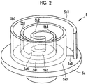
Fig. 2 is a perspective view showing the orbiting scroll ofFigs. 1A and 1B . -
Fig. 3 is a plan view showing an end plate flat portion provided in the fixed scroll. -
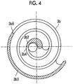
Fig. 4 is a plan view showing a wall flat portion provided in the fixed scroll. -
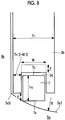
Fig. 5 is a schematic view showing a wall which is displayed to extend in a spiral direction. -
Fig. 6 is a partially enlarged view showing a region indicated by a reference sign Z inFig. 1B in an enlarged manner. -
Fig. 7A is a side view showing a tip seal clearance of a portion shown inFig. 6 and a state where the tip seal clearance relatively decreases. -
Fig. 7B is a side view showing the tip seal clearance of the portion shown inFig. 6 and a state where the tip seal clearance relatively increases. -
Fig. 8 is a horizontal sectional view around a tooth tip in a wall inclined portion. -
Fig. 9A is a plan view of a tooth bottom showing a tooth bottom shape of an end plate. -
Fig. 9B is a schematic view showing a depth of a central portion of the tooth bottom ofFig. 9A . -
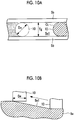
Fig. 10A show a method for processing the tooth bottom of the end plate and is a plan view of the tooth bottom. -
Fig. 10B is a side view corresponding toFig. 10A and showing the tooth bottom. -
Fig. 11 is a horizontal sectional view of the tooth bottom of the end plate. -
Fig. 12 is a horizontal sectional view around the tooth tip in the wall flat portion. -
Fig. 13 is a longitudinal section view showing a combination with a scroll which does not have a step portion. -
Fig. 14 is a longitudinal section view showing a combination with a stepped scroll. - Hereinafter, an embodiment according to the present invention will be described with reference to the drawings.
- In
Figs. 1A and 1B , a fixed scroll (first scroll member) 3 and an orbiting scroll (second scroll member) 5 of a scroll compressor (scroll fluid machine) 1 are shown. For example, thescroll compressor 1 is used as a compressor which compresses a gas refrigerant (fluid) which performs a refrigerating cycle of an air conditioner or the like. - Each of the fixed
scroll 3 and theorbiting scroll 5 is a metal compression mechanism which is formed of an aluminum alloy or steel, and is accommodated in a housing (not shown). The fixedscroll 3 and theorbiting scroll 5 suck a fluid, which is introduced into the housing, from an outer peripheral side, and discharge the compressed fluid from adischarge port 3c positioned at a center of the fixedscroll 3 to the outside. - The fixed
scroll 3 is fixed to the housing, and as shown inFigs. 1A , includes an approximately disk-shaped end plate (first end plate) 3a, and a spiral wall (first wall) 3b which is erected on one side surface of theend plate 3a. Theorbiting scroll 5 includes an approximately disk-shaped end plate (second end plate) 5a and a spiral wall (second wall) 5b which is erected on one side surface of theend plate 5a. For example, a spiral shape of each of thewalls - The fixed
scroll 3 and theorbiting scroll 5 are assembled to each other such that centers thereof are separated from each other by an orbiting radius p, thewalls walls end plates walls scrolls orbiting scroll 5 performs a revolution orbiting movement around the fixedscroll 3 by a rotation prevention mechanism such as an Oldham ring (not shown). - As shown in
Fig. 1A , an inclined portion is provided, in which an inter-facing surface distance L between bothend plates spiral walls - As shown in
Fig. 2 , in thewall 5b of theorbiting scroll 5, a wall inclined portion 5b1 whose height continuously decreases from an outer peripheral side toward an inner peripheral side is provided. In a tooth bottom surface of the fixedscroll 3 facing a tooth tip of the wall inclined portion 5b1, an end plate inclined portion 3a1 (refer toFig. 1A ) which is inclined according to an inclination of the wall inclined portion 5b1 is provided. A continuously inclined portion is constituted by the wall inclined portion 5b1 and the end plate inclined portion 3a1. Similarly, a wall inclined portion 3b1 whose height is continuously inclined from the outer peripheral side toward the inner peripheral side is provided on thewall 3b of the fixedscroll 3, and an end plate inclined portion 5a1 facing a tooth tip of the wall inclined portion 3b1 is provided on theend plate 5a of theorbiting scroll 5. - In addition, the meaning of the continuity in the inclined portion in the present embodiment is not limited to a smoothly connected inclination but also includes an inclined portion in which small step portions inevitably generated during processing are connected to each other in a stepwise fashion and the inclined portion is continuously inclined as a whole. However, the inclined portion does not include a large step portion such as a so-called stepped scroll.
- Coating is applied to the wall inclined portions 3b1 and 5b1 and/or the end plate inclined portions 3a1 and 5a1. For example, the coating includes manganese phosphate processing, nickel phosphorus plating, or the like.
- As shown in
Fig. 2 , wall flat portions 5b2 and 5b3 each having a constant height are respectively provided on the innermost peripheral side and the outermost peripheral side of thewall 5b of theorbiting scroll 5. Each of the wall flat portions 5b2 and 5b3 is provided over a region of 180° around a center 02 (refer toFig. 1A ) of theorbiting scroll 5. Wall inclined connection portions 5b4 and 5b5 which become curved portions are respectively provided at positions at which the wall flat portions 5b2 and 5b3 and the wall inclined portion 5b1 are connected to each other. - Similarly, in the tooth bottom of the
end plate 5a of theorbiting scroll 5, end plate flat portions 5a2 and 5a3 each having a constant height are provided. Each of the end plate flat portions 5a2 and 5a3 is provided over a region of 180° around the center of theorbiting scroll 5. End plate inclined connection portions 5a4 and 5a5 which become curved portions are respectively provided at positions at which the end plate flat portions 5a2 and 5a3 and the end plate inclined portion 5a1 are connected to each other. - As shown by hatching in
Figs. 3 and4 , similarly to theorbiting scroll 5, in the fixedscroll 3, end plate flat portions 3a2 and 3a3, wall flat portions 3b2 and 3b3, end plate inclined connection portions 3a4 and 3a5, and wall inclined connection portions 3b4 and 3b5 are provided. -
Fig. 5 shows thewalls Fig. 5 , the wall flat portions 3b2 and 5b2 on the innermost peripheral side are provided over a distance D2, and the wall flat portions 3b3 and 5b3 on the outermost peripheral side are provided over a distance D3. Each of the distance D2 and the distance D3 is a length corresponding to the region which becomes 180° around each of the centers O1 and 02 of therespective scrolls 
- In this way, the inclination ϕ of the inclined portion is constant in a circumferential direction in which each of the
spiral walls -
Fig. 6 is an enlarged view showing a region indicated by a reference sign Z inFig. 1B in an enlarged manner. As shownFig. 6 , atip seal 7 is provided in the tooth tip of thewall 3b of the fixedscroll 3. Thetip seal 7 is formed of a resin and comes into contact with the tooth bottom of theend plate 5a of the facing orbitingscroll 5 so as to perform sealing for a fluid. Thetip seal 7 is accommodated in atip seal groove 3d which is formed on the tooth tip of thewall 3b in the circumferential direction. A compressed fluid enters thetip seal groove 3d, presses thetip seal 7 from a rear surface thereof to push thetip seal 7 toward the tooth bottom side, and thus, thetip seal 7 comes into contact with the facing the tooth bottom. In addition, a tip seal is also provided in the tooth tip of thewall 5b of theorbiting scroll 5. - As shown in
Figs. 7A and7B , a height Hc of thetip seal 7 in the height direction of thewall 3b is constant in the circumferential direction. - If both the
scrolls Fig. 7A , a tip clearance T is small, and inFig. 7B , the tip clearance T is large. Even when the tip clearance T is changed by an orbiting movement, thetip seal 7 is pressed toward the tooth bottom side of theend plate 5a by the compressed fluid from the rear surface, and thetip seal 7 can follow the tooth bottom so as to peform sealing for the tooth bottom. -
Fig. 8 is a horizontal sectional view around the tooth tip when viewed from a sectional plane of the wall inclined portion 3b1 orthogonal in the spiral direction. In other words,Fig. 8 is a horizontal sectional view around the tooth tip when the wall inclined portion 3b1 from the wall inclined connection portion 3b4 on the inner peripheral side shown inFig. 5 to the wall inclined connection portion 3b5 on the outer peripheral side shown inFig. 5 is cut in a direction perpendicular to a paper surface. In addition, the tooth tip and thetip seal 7 of theorbiting scroll 5 are similarly configured. - The state shown in
Fig. 8 is a state where thewall 5b of theorbiting scroll 5 and thewall 3b of the fixedscroll 3 adjacent to each other are closest to each other during an operation. Thetip seal 7 is accommodated in thetip seal groove 3d formed in the tooth tip of the tip of thewall 3b. A horizontal cross section of thetip seal 7 has a substantially rectangular shape, and a flat tip surface (lower surface) 7a protrudes from the tooth tip of thewall 3b by the protrusion amount δ. In addition, the protrusion amount δ is an amount only during the operation, and in a case where a gas pressure is not applied to the back surface of the tip seal when the operation is stopped, the tip seal may sink into the tip seal groove and the protrusion amount may be less than or equal to zero. - The tooth bottom of the
end plate 5a facing thewall 3b has an arc shape in which a central portion in the width direction is formed deeper than both side portions 5d3. The arc shape is a radius R, which will be described later. Accordingly, the cross section of the tooth bottom of theend plate 5a is formed in a shape of a turtle. A horizontal cross section of the tooth bottom of theend plate 5a formed in the shape of a turtle is formed over the entire end plate inclined portion 5a1. - As shown in
Figs. 9A and 9B , the above-described shape of the tooth bottom of theend plate 5a is generated by forming a contour line Ct. The contour line Ct has a width Tg of the tooth bottom of theend plate 5a as a diameter and is formed in a semicircular arc which protrudes in a height increase direction (left side inFigs. 9A and 9B ) of the end plate inclined portion 5a1. That is, a radius of the contour line Ct is Tg/2. As can be seen fromFig. 9B , the inclination of the end plate inclined portion 5a1 is ϕ (refer toFig. 5 ), and thus, a depression amount Δh of a central portion 5d2 of the tooth bottom from both side portions 5d3 is represented by the following Expression.
- The shape of the tooth bottom shown in
Fig. 9A is obtained by performing processing using anend mill 10 shown inFigs. 10A and 10B . A diameter De of theend mill 10 is the same as the width Tg of the tooth bottom. By theend mill 10, the tooth bottom is processed with one pass in one direction in which the inclination increases. The processing is performed such that a rotation axis of theend mill 10 is parallel to an axis passing through the center 02 (refer toFig. 1A ) of theorbiting scroll 5. Accordingly, as shown inFig. 9A , the contour line Ct having a semicircular arc shape is formed. - As shown in
Fig. 11 , the tooth bottom of theend plate 5a is formed in an arc shape having a radius R. That is, the tooth bottom is formed in an arc shape having the radius R which passes through the central portion 5d2 protruding by the depression amount Δh from both side portions 5d3 and both side portions 5d3. - As shown in
Fig. 12 , in each of the end plate flat portions 5a2 and 5a3, the tooth bottom of theend plate 5a is flat. This is because each of the end plate flat portions 5a2 and 5a3 is not inclined unlike the end plate inclined portions 5a1, and thus, the flat surface is formed by processing of theend mill 10. Accordingly, theentire tip surface 7a which becomes a flat surface of thetip seal 7 comes into contact with the tooth bottom, a protrusion amount oftip seal 7 protruding from the tooth tip is approximately 0 to slightly protruding, and is smaller than the protrusion amount δ (seeFig. 8 ). In addition, the state shown inFig. 12 shows a state in which thewall 5b of theorbiting scroll 5 and thewall 3b of the fixedscroll 3 adjacent to each other are closest to each other. The height Hc of thetip seal 7 in the flat portion is equal to the height Hc of the tip seal in the inclined portion. - Next, as shown in
Fig. 8 , setting of the protrusion amount δ in which thetip seal 7 protrudes from the tooth tip will be described. The protrusion amount δ is expressed as a function of the inclination ϕ, the end mill diameter De, a tooth thickness of thewall 3b, and a tip seal groove width W. The tooth thickness of thewall 3b means a width on one side of the tooth tip of thewall 3b excluding thetip seal groove 3d, and when the thickness of thewall 3b is Tr, and the tooth thickness can be expressed by Tr/2 - W/2. - The protrusion amount δ is as follows.

- A depth of the
tip seal groove 3d can be reduced by an amount corresponding to the projection amount δ expressed by the above Expression. Specifically, compared to thetip seal groove 3d of the tooth tip facing the end plate flat portions 5a2 and 5a3 as shown inFig. 12 , in thetip seal groove 3d of the tooth tip facing the end plate inclined portion 5a1 as shown inFig. 8 , the groove depth can be reduced by the protrusion amount δ. - The above-described
scroll compressor 1 is operated as follows. Theorbiting scroll 5 performs the revolution orbiting movement around the fixedscroll 3 by a drive source such as an electric motor (not shown). Accordingly, the fluid is sucked from the outer peripheral sides of therespective scrolls respective walls respective end plates discharge port 3c formed in the fixedscroll 3. When the fluid is compressed, the fluid is compressed in the height directions of thewalls - According to the present embodiment, the following operational effects are exerted. If each of the end plate inclined portions 3a1 and 5a1 has the shape in which the central part is deeper than the side portion in the width direction, the tip of the
tip seal 7 protrudes from thetip seal groove 3d by an amount which is deeper than the side portion (refer toFig. 8 ). Accordingly, compared to the case where theend plates Fig. 12 ), a back clearance between the bottom portion of thetip seal groove 3d and the back surface of thetip seal 7. If the back clearance increases, the refrigerant flows from a high-pressure side compression chamber to a low-pressure side compression chamber through the back clearance, and thus, a fluid loss is generated. Accordingly, the protrusion amount δ oftip seal 7 in each of the wall inclined portions 3b1 and 5b1 is made larger than the protrusion amount oftip seal 7 in each of the wall flat portions 3b2, 3b3, 5b2 and 5b3 such that an increase in the back clearance in the inclined portion is suppressed. Accordingly, the fluid loss can be suppressed as much as possible. - The projection amount δ of the
tip seal 7 is set to be smallest in the case where the wall inclined portions 3b1 and 5b1 are closest to the adjacent wall inclined portions (the state shown inFig. 8 ). Accordingly, the fluid loss can be suppressed as much as possible. - In the case where the wall inclined portions 3b1 and 5b1 are closest to each other, if the protrusion amount δ of the
tip seal 7 is set as in the above Expression (3) based on a depth (refer toFig. 8 ) at which the tip of thetip seal 7 abuts on a position deeper than the side portion of each of the end plate inclined portions 3a1 and 5a1, the back clearance of the inclined portion can be made as small as possible. - In addition, in the present embodiment, in the present embodiment, the back clearance is adjusted by the depth of the
tip seal groove 3d. However, the back clearance may be adjusted by the height Hc (refer toFig. 8 ) of thetip seal 7 or may be adjusted using both the depth of thetip seal groove 3d and the height Hc of thetip seal 7. - Moreover, in the present embodiment, although the end plate inclined portions 3a1 and 5a1 and the wall inclined portions 3b1 and 5b1 are provided on both the
scrolls scrolls Fig. 13 , in a case where the wall inclined portion 5b1 is provided in one wall (for example, orbiting scroll 5) and the end plate inclined portion 3a1 is provided in theother end plate 3a, the other wall and oneend plate 5a may be flat. In addition, as shown inFig. 14 , a shape combined with a stepped shape of the related art may be adopted, that is, the shape in which the end plate inclined portion 3a1 is provided in theend plate 3a of the fixedscroll 3 may be combined with a shape in which the step portion is provided in theend plate 5a of theorbiting scroll 5. - In the present embodiment, the wall flat portions 3b2, 3b3, 5b2, and 5b3 and the end plate flat portions 3a2, 3a3, 5a2, and 5a3 are provided. However, the flat portions on the inne(3a1, 5b1) r peripheral side and/or the outer peripheral side may be omitted, and the inclined portion may be provided so as to extend to the
entire walls - In the present embodiment, the scroll compressor is described. However, the present invention can be applied to a scroll expander which is used as an expander. Reference Signs List
-
- 1:
- scroll compressor (scroll fluid machine)
- 3:
- fixed scroll (first scroll member)
- 3a:
- end plate (first end plate)
- 3a1:
- end plate inclined portion
- 3a2:
- end plate flat portion
- 3a3:
- end plate flat portion
- 3a4:
- end plate inclined connection portion
- 3a5:
- end plate inclined connection portion
- 3b:
- wall (first wall)
- 3b1:
- wall inclined portion
- 3b2:
- wall flat portion
- 3b3:
- wall flat portion
- 3b4:
- wall inclined connection portion
- 3b5:
- wall inclined connection portion
- 3c:
- discharge port
- 3d:
- tip seal groove
- 5:
- orbiting scroll (second scroll member)
- 5a:
- end plate (second end plate)
- 5a1:
- end plate inclined portion
- 5a2:
- end plate flat portion
- 5a3:
- end plate flat portion
- 5a4:
- end plate inclined connection portion
- 5a5:
- end plate inclined connection portion
- 5b:
- wall (second wall)
- 5b1:
- wall inclined portion
- 5b2:
- wall flat portion
- 5b3:
- wall flat portion
- 5b4:
- wall inclined connection portion
- 5b5:
- wall inclined connection portion
- 7:
- tip seal
- 7a:
- tip surface
- 10:
- end mill
- Ct:
- contour line
- D1:
- division position (of tip seal)
- De:
- end mill diameter
- Hc:
- height of tip seal
- L:
- inter-facing surface distance
- T:
- tip clearance
- Tg:
- width of tooth bottom
- Tr:
- thickness of wall
- W:
- tip seal groove width
- δ:
- protrusion amount (of tip seal)
- ϕ:
- inclination
- Δh:
- depression amount
Claims (4)
- A scroll fluid machine comprising:a first scroll member having a first end plate on which a spiral first wall is provided;a second scroll member having a second end plate on which a spiral second wall is provided, the second end plate being disposed to face the first end plate and the second wall meshing with the first wall such that the second scroll member performs a revolution orbiting movement relative to the first scroll member; andan inclined portion in which an inter-facing surface distance between the first end plate and the second end plate facing each other continuously decreases from outer peripheral sides of the first wall and the second wall toward inner peripheral sides thereof,wherein at least one of the first wall and the second wall has a wall inclined portion, in which a height of the wall continuously decreases from the outer peripheral side toward the inner peripheral side, to form the inclined portion,wherein at least one of the first end plate and the second end plate has an end plate inclined portion in which a tooth bottom surface facing a tooth tip of the wall inclined portion is inclined according to an inclination of the wall inclined portion,wherein a wall flat portion whose height is not changed is provided on outermost peripheral portions and/or innermost peripheral portions of the first wall and the second wall,wherein an end plate flat portion corresponding to the wall flat portion is provided on the first end plate and the second end plate,wherein a tip seal which comes into contact with the facing end plate to perform sealing for a fluid is provided in a tip seal groove formed in a tooth tip of the wall,wherein the end plate inclined portion is configured such that a central portion is deeper than a side portion in a width direction orthogonal to a spiral direction of the wall, andwherein during an operation, a protrusion amount measured when the tip seal protrudes from the tooth tip of the wall inclined portion in the wall inclined portion and comes into contact with the facing end plate is larger than a protrusion amount measured when the tip seal protrudes from a tooth tip of the wall flat portion in the wall flat portion and comes into contact with the facing end plate.
- The scroll fluid machine according to claim 1,
wherein a thickness of the tip seal in a height direction of the wall is constant in the spiral direction of the wall, and
wherein a depth of the tip seal groove is shallower in the wall inclined portion than in the wall flat portion. - A scroll fluid machine comprising:a first scroll member having a first end plate on which a spiral first wall is provided;a second scroll member having a second end plate on which a spiral second wall is provided, the second end plate being disposed to face the first end plate and the second wall meshing with the first wall such that the second scroll member performs a revolution orbiting movement relative to the first scroll member; andan inclined portion in which an inter-facing surface distance between the first end plate and the second end plate facing each other continuously decreases from outer peripheral sides of the first wall and the second wall toward inner peripheral sides thereof,wherein at least one of the first wall and the second wall has a wall inclined portion, in which a height of the wall continuously decreases from the outer peripheral side toward the inner peripheral side, to form the inclined portion,wherein at least one of the first end plate and the second end plate has an end plate inclined portion in which a tooth bottom surface facing a tooth tip of the wall inclined portion is inclined according to an inclination of the wall inclined portion,wherein a tip seal which comes into contact with the facing end plate inclined portion to perform sealing for a fluid is provided in a tip seal groove formed on each tooth tip of the first wall and the second wall corresponding to the inclined portion,wherein the end plate inclined portion is configured such that a central portion is deeper than a side portion in a width direction orthogonal to a spiral direction of the wall, andwherein during an operation, a protrusion amount measured when the tip seal protrudes from the tooth tip of the wall inclined portion and comes into contact with the facing end plate is smallest when the wall inclined portion is closest to the adjacent wall inclined portion.
- The scroll fluid machine according to any one of claims 1 to 3,
wherein in a case where the wall inclined portion is closest to the adjacent wall inclined portion, a protrusion amount of the tip seal is determined based on such a depth that a tip of the tip seal abuts on a position deeper than the side portion of the end plate inclined portion.
Applications Claiming Priority (2)
| Application Number | Priority Date | Filing Date | Title |
|---|---|---|---|
| JP2017158114A JP6386144B1 (en) | 2017-08-18 | 2017-08-18 | Scroll fluid machinery |
| PCT/JP2018/023648 WO2019035276A1 (en) | 2017-08-18 | 2018-06-21 | Scroll fluid machine |
Publications (3)
| Publication Number | Publication Date |
|---|---|
| EP3604812A1 true EP3604812A1 (en) | 2020-02-05 |
| EP3604812A4 EP3604812A4 (en) | 2020-02-05 |
| EP3604812B1 EP3604812B1 (en) | 2021-02-17 |
Family
ID=63444265
Family Applications (1)
| Application Number | Title | Priority Date | Filing Date |
|---|---|---|---|
| EP18846505.8A Active EP3604812B1 (en) | 2017-08-18 | 2018-06-21 | Scroll fluid machine |
Country Status (5)
| Country | Link |
|---|---|
| US (1) | US11204034B2 (en) |
| EP (1) | EP3604812B1 (en) |
| JP (1) | JP6386144B1 (en) |
| CN (1) | CN110573739B (en) |
| WO (1) | WO2019035276A1 (en) |
Families Citing this family (1)
| Publication number | Priority date | Publication date | Assignee | Title |
|---|---|---|---|---|
| US11971034B2 (en) * | 2020-07-09 | 2024-04-30 | Hitachi Industrial Equipment Systems Co., Ltd. | Scroll type fluid machine |
Family Cites Families (20)
| Publication number | Priority date | Publication date | Assignee | Title |
|---|---|---|---|---|
| JPS6176185U (en) * | 1984-10-26 | 1986-05-22 | ||
| JPH01119892U (en) * | 1988-02-05 | 1989-08-14 | ||
| JPH05235386A (en) | 1992-02-21 | 1993-09-10 | Canon Inc | Solar cell and manufacturing method thereof |
| JPH06235386A (en) * | 1993-02-10 | 1994-08-23 | Mitsubishi Electric Corp | Scroll compressor |
| JP3046486B2 (en) | 1993-12-28 | 2000-05-29 | 株式会社日立製作所 | Scroll type fluid machine |
| JPH0828481A (en) | 1994-07-21 | 1996-01-30 | Zexel Corp | Variable displacement-type vane compressor |
| JP2008240739A (en) * | 1994-07-13 | 2008-10-09 | Hitachi Ltd | Scroll processing method and apparatus |
| JP3810102B2 (en) * | 1994-12-22 | 2006-08-16 | 株式会社デンソー | Scroll compressor |
| JPH09250467A (en) | 1996-03-18 | 1997-09-22 | Tokico Ltd | Scroll type fluid machinery |
| JP4301713B2 (en) | 2000-08-28 | 2009-07-22 | 三菱重工業株式会社 | Scroll compressor |
| KR100439651B1 (en) * | 2000-11-06 | 2004-07-12 | 미츠비시 쥬고교 가부시키가이샤 | Scroll compressor |
| JP3881861B2 (en) * | 2001-02-02 | 2007-02-14 | 三菱重工業株式会社 | Scroll compressor |
| JP2002266778A (en) | 2001-03-07 | 2002-09-18 | Ntn Corp | Tip seal and its manufacturing method |
| JP4709439B2 (en) | 2001-07-24 | 2011-06-22 | 三菱重工業株式会社 | Scroll compressor |
| JP2005330850A (en) | 2004-05-18 | 2005-12-02 | Ntn Corp | Tip seal |
| JP2009228476A (en) * | 2008-03-19 | 2009-10-08 | Daikin Ind Ltd | Scroll compressor |
| JP2010196663A (en) * | 2009-02-26 | 2010-09-09 | Mitsubishi Heavy Ind Ltd | Compressor |
| JP5931689B2 (en) * | 2012-10-18 | 2016-06-08 | 三菱重工業株式会社 | Scroll compressor |
| JP6180860B2 (en) | 2013-09-11 | 2017-08-16 | 三菱重工業株式会社 | Scroll compressor |
| JP6325041B2 (en) | 2016-08-31 | 2018-05-16 | 三菱重工サーマルシステムズ株式会社 | Scroll fluid machinery and tip seal |
-
2017
- 2017-08-18 JP JP2017158114A patent/JP6386144B1/en active Active
-
2018
- 2018-06-21 EP EP18846505.8A patent/EP3604812B1/en active Active
- 2018-06-21 CN CN201880028441.9A patent/CN110573739B/en active Active
- 2018-06-21 US US16/608,109 patent/US11204034B2/en active Active
- 2018-06-21 WO PCT/JP2018/023648 patent/WO2019035276A1/en not_active Ceased
Also Published As
| Publication number | Publication date |
|---|---|
| JP6386144B1 (en) | 2018-09-05 |
| JP2019035387A (en) | 2019-03-07 |
| EP3604812A4 (en) | 2020-02-05 |
| EP3604812B1 (en) | 2021-02-17 |
| US11204034B2 (en) | 2021-12-21 |
| CN110573739A (en) | 2019-12-13 |
| WO2019035276A1 (en) | 2019-02-21 |
| CN110573739B (en) | 2021-10-15 |
| US20200095993A1 (en) | 2020-03-26 |
Similar Documents
| Publication | Publication Date | Title |
|---|---|---|
| EP3460245B1 (en) | Scroll fluid machine and tip seal | |
| EP3428451B1 (en) | Scroll fluid machine, and method for processing scroll member | |
| EP3438458B1 (en) | Scroll fluid machine and method for producing same | |
| EP3584444B1 (en) | Scroll fluid machine | |
| EP3604812B1 (en) | Scroll fluid machine | |
| EP3722608B1 (en) | Scroll fluid machine and scroll member used therein | |
| EP3441615B1 (en) | Scroll fluid machine | |
| AU2019225271A1 (en) | Scroll fluid machine | |
| EP3444475B1 (en) | Scroll fluid machine | |
| EP3754197B1 (en) | Scroll fluid machine and machining method of scroll member | |
| JP6505906B2 (en) | Scroll fluid machine | |
| EP3739213B1 (en) | Scroll fluid machine | |
| EP3444476B1 (en) | Scroll fluid machine | |
| JP6336535B2 (en) | Scroll fluid machine and scroll member machining method |
Legal Events
| Date | Code | Title | Description |
|---|---|---|---|
| STAA | Information on the status of an ep patent application or granted ep patent |
Free format text: STATUS: THE INTERNATIONAL PUBLICATION HAS BEEN MADE |
|
| PUAI | Public reference made under article 153(3) epc to a published international application that has entered the european phase |
Free format text: ORIGINAL CODE: 0009012 |
|
| STAA | Information on the status of an ep patent application or granted ep patent |
Free format text: STATUS: REQUEST FOR EXAMINATION WAS MADE |
|
| 17P | Request for examination filed |
Effective date: 20191029 |
|
| A4 | Supplementary search report drawn up and despatched |
Effective date: 20200107 |
|
| AK | Designated contracting states |
Kind code of ref document: A1 Designated state(s): AL AT BE BG CH CY CZ DE DK EE ES FI FR GB GR HR HU IE IS IT LI LT LU LV MC MK MT NL NO PL PT RO RS SE SI SK SM TR |
|
| AX | Request for extension of the european patent |
Extension state: BA ME |
|
| RIC1 | Information provided on ipc code assigned before grant |
Ipc: F01C 21/10 20060101ALI20200907BHEP Ipc: F04C 27/00 20060101ALI20200907BHEP Ipc: F01C 1/02 20060101ALI20200907BHEP Ipc: F01C 19/08 20060101ALI20200907BHEP Ipc: F04C 18/02 20060101AFI20200907BHEP Ipc: F01C 21/08 20060101ALI20200907BHEP |
|
| GRAP | Despatch of communication of intention to grant a patent |
Free format text: ORIGINAL CODE: EPIDOSNIGR1 |
|
| STAA | Information on the status of an ep patent application or granted ep patent |
Free format text: STATUS: GRANT OF PATENT IS INTENDED |
|
| DAV | Request for validation of the european patent (deleted) | ||
| DAX | Request for extension of the european patent (deleted) | ||
| INTG | Intention to grant announced |
Effective date: 20201016 |
|
| GRAS | Grant fee paid |
Free format text: ORIGINAL CODE: EPIDOSNIGR3 |
|
| GRAA | (expected) grant |
Free format text: ORIGINAL CODE: 0009210 |
|
| STAA | Information on the status of an ep patent application or granted ep patent |
Free format text: STATUS: THE PATENT HAS BEEN GRANTED |
|
| AK | Designated contracting states |
Kind code of ref document: B1 Designated state(s): AL AT BE BG CH CY CZ DE DK EE ES FI FR GB GR HR HU IE IS IT LI LT LU LV MC MK MT NL NO PL PT RO RS SE SI SK SM TR |
|
| REG | Reference to a national code |
Ref country code: GB Ref legal event code: FG4D |
|
| REG | Reference to a national code |
Ref country code: CH Ref legal event code: EP |
|
| REG | Reference to a national code |
Ref country code: DE Ref legal event code: R096 Ref document number: 602018012809 Country of ref document: DE |
|
| REG | Reference to a national code |
Ref country code: AT Ref legal event code: REF Ref document number: 1361839 Country of ref document: AT Kind code of ref document: T Effective date: 20210315 |
|
| REG | Reference to a national code |
Ref country code: IE Ref legal event code: FG4D |
|
| REG | Reference to a national code |
Ref country code: LT Ref legal event code: MG9D |
|
| REG | Reference to a national code |
Ref country code: NL Ref legal event code: MP Effective date: 20210217 |
|
| PG25 | Lapsed in a contracting state [announced via postgrant information from national office to epo] |
Ref country code: LT Free format text: LAPSE BECAUSE OF FAILURE TO SUBMIT A TRANSLATION OF THE DESCRIPTION OR TO PAY THE FEE WITHIN THE PRESCRIBED TIME-LIMIT Effective date: 20210217 Ref country code: NO Free format text: LAPSE BECAUSE OF FAILURE TO SUBMIT A TRANSLATION OF THE DESCRIPTION OR TO PAY THE FEE WITHIN THE PRESCRIBED TIME-LIMIT Effective date: 20210517 Ref country code: PT Free format text: LAPSE BECAUSE OF FAILURE TO SUBMIT A TRANSLATION OF THE DESCRIPTION OR TO PAY THE FEE WITHIN THE PRESCRIBED TIME-LIMIT Effective date: 20210617 Ref country code: BG Free format text: LAPSE BECAUSE OF FAILURE TO SUBMIT A TRANSLATION OF THE DESCRIPTION OR TO PAY THE FEE WITHIN THE PRESCRIBED TIME-LIMIT Effective date: 20210517 Ref country code: HR Free format text: LAPSE BECAUSE OF FAILURE TO SUBMIT A TRANSLATION OF THE DESCRIPTION OR TO PAY THE FEE WITHIN THE PRESCRIBED TIME-LIMIT Effective date: 20210217 Ref country code: GR Free format text: LAPSE BECAUSE OF FAILURE TO SUBMIT A TRANSLATION OF THE DESCRIPTION OR TO PAY THE FEE WITHIN THE PRESCRIBED TIME-LIMIT Effective date: 20210518 Ref country code: FI Free format text: LAPSE BECAUSE OF FAILURE TO SUBMIT A TRANSLATION OF THE DESCRIPTION OR TO PAY THE FEE WITHIN THE PRESCRIBED TIME-LIMIT Effective date: 20210217 |
|
| REG | Reference to a national code |
Ref country code: AT Ref legal event code: MK05 Ref document number: 1361839 Country of ref document: AT Kind code of ref document: T Effective date: 20210217 |
|
| PG25 | Lapsed in a contracting state [announced via postgrant information from national office to epo] |
Ref country code: SE Free format text: LAPSE BECAUSE OF FAILURE TO SUBMIT A TRANSLATION OF THE DESCRIPTION OR TO PAY THE FEE WITHIN THE PRESCRIBED TIME-LIMIT Effective date: 20210217 Ref country code: RS Free format text: LAPSE BECAUSE OF FAILURE TO SUBMIT A TRANSLATION OF THE DESCRIPTION OR TO PAY THE FEE WITHIN THE PRESCRIBED TIME-LIMIT Effective date: 20210217 Ref country code: PL Free format text: LAPSE BECAUSE OF FAILURE TO SUBMIT A TRANSLATION OF THE DESCRIPTION OR TO PAY THE FEE WITHIN THE PRESCRIBED TIME-LIMIT Effective date: 20210217 Ref country code: LV Free format text: LAPSE BECAUSE OF FAILURE TO SUBMIT A TRANSLATION OF THE DESCRIPTION OR TO PAY THE FEE WITHIN THE PRESCRIBED TIME-LIMIT Effective date: 20210217 Ref country code: NL Free format text: LAPSE BECAUSE OF FAILURE TO SUBMIT A TRANSLATION OF THE DESCRIPTION OR TO PAY THE FEE WITHIN THE PRESCRIBED TIME-LIMIT Effective date: 20210217 |
|
| PG25 | Lapsed in a contracting state [announced via postgrant information from national office to epo] |
Ref country code: IS Free format text: LAPSE BECAUSE OF FAILURE TO SUBMIT A TRANSLATION OF THE DESCRIPTION OR TO PAY THE FEE WITHIN THE PRESCRIBED TIME-LIMIT Effective date: 20210617 |
|
| PG25 | Lapsed in a contracting state [announced via postgrant information from national office to epo] |
Ref country code: EE Free format text: LAPSE BECAUSE OF FAILURE TO SUBMIT A TRANSLATION OF THE DESCRIPTION OR TO PAY THE FEE WITHIN THE PRESCRIBED TIME-LIMIT Effective date: 20210217 Ref country code: CZ Free format text: LAPSE BECAUSE OF FAILURE TO SUBMIT A TRANSLATION OF THE DESCRIPTION OR TO PAY THE FEE WITHIN THE PRESCRIBED TIME-LIMIT Effective date: 20210217 Ref country code: SM Free format text: LAPSE BECAUSE OF FAILURE TO SUBMIT A TRANSLATION OF THE DESCRIPTION OR TO PAY THE FEE WITHIN THE PRESCRIBED TIME-LIMIT Effective date: 20210217 Ref country code: AT Free format text: LAPSE BECAUSE OF FAILURE TO SUBMIT A TRANSLATION OF THE DESCRIPTION OR TO PAY THE FEE WITHIN THE PRESCRIBED TIME-LIMIT Effective date: 20210217 |
|
| REG | Reference to a national code |
Ref country code: DE Ref legal event code: R097 Ref document number: 602018012809 Country of ref document: DE |
|
| PG25 | Lapsed in a contracting state [announced via postgrant information from national office to epo] |
Ref country code: DK Free format text: LAPSE BECAUSE OF FAILURE TO SUBMIT A TRANSLATION OF THE DESCRIPTION OR TO PAY THE FEE WITHIN THE PRESCRIBED TIME-LIMIT Effective date: 20210217 Ref country code: SK Free format text: LAPSE BECAUSE OF FAILURE TO SUBMIT A TRANSLATION OF THE DESCRIPTION OR TO PAY THE FEE WITHIN THE PRESCRIBED TIME-LIMIT Effective date: 20210217 Ref country code: RO Free format text: LAPSE BECAUSE OF FAILURE TO SUBMIT A TRANSLATION OF THE DESCRIPTION OR TO PAY THE FEE WITHIN THE PRESCRIBED TIME-LIMIT Effective date: 20210217 |
|
| PLBE | No opposition filed within time limit |
Free format text: ORIGINAL CODE: 0009261 |
|
| STAA | Information on the status of an ep patent application or granted ep patent |
Free format text: STATUS: NO OPPOSITION FILED WITHIN TIME LIMIT |
|
| 26N | No opposition filed |
Effective date: 20211118 |
|
| PG25 | Lapsed in a contracting state [announced via postgrant information from national office to epo] |
Ref country code: ES Free format text: LAPSE BECAUSE OF FAILURE TO SUBMIT A TRANSLATION OF THE DESCRIPTION OR TO PAY THE FEE WITHIN THE PRESCRIBED TIME-LIMIT Effective date: 20210217 Ref country code: MC Free format text: LAPSE BECAUSE OF FAILURE TO SUBMIT A TRANSLATION OF THE DESCRIPTION OR TO PAY THE FEE WITHIN THE PRESCRIBED TIME-LIMIT Effective date: 20210217 Ref country code: AL Free format text: LAPSE BECAUSE OF FAILURE TO SUBMIT A TRANSLATION OF THE DESCRIPTION OR TO PAY THE FEE WITHIN THE PRESCRIBED TIME-LIMIT Effective date: 20210217 |
|
| REG | Reference to a national code |
Ref country code: CH Ref legal event code: PL |
|
| PG25 | Lapsed in a contracting state [announced via postgrant information from national office to epo] |
Ref country code: SI Free format text: LAPSE BECAUSE OF FAILURE TO SUBMIT A TRANSLATION OF THE DESCRIPTION OR TO PAY THE FEE WITHIN THE PRESCRIBED TIME-LIMIT Effective date: 20210217 |
|
| REG | Reference to a national code |
Ref country code: BE Ref legal event code: MM Effective date: 20210630 |
|
| PG25 | Lapsed in a contracting state [announced via postgrant information from national office to epo] |
Ref country code: LU Free format text: LAPSE BECAUSE OF NON-PAYMENT OF DUE FEES Effective date: 20210621 |
|
| PG25 | Lapsed in a contracting state [announced via postgrant information from national office to epo] |
Ref country code: LI Free format text: LAPSE BECAUSE OF NON-PAYMENT OF DUE FEES Effective date: 20210630 Ref country code: IT Free format text: LAPSE BECAUSE OF FAILURE TO SUBMIT A TRANSLATION OF THE DESCRIPTION OR TO PAY THE FEE WITHIN THE PRESCRIBED TIME-LIMIT Effective date: 20210217 Ref country code: IE Free format text: LAPSE BECAUSE OF NON-PAYMENT OF DUE FEES Effective date: 20210621 Ref country code: CH Free format text: LAPSE BECAUSE OF NON-PAYMENT OF DUE FEES Effective date: 20210630 |
|
| PG25 | Lapsed in a contracting state [announced via postgrant information from national office to epo] |
Ref country code: IS Free format text: LAPSE BECAUSE OF FAILURE TO SUBMIT A TRANSLATION OF THE DESCRIPTION OR TO PAY THE FEE WITHIN THE PRESCRIBED TIME-LIMIT Effective date: 20210617 |
|
| PG25 | Lapsed in a contracting state [announced via postgrant information from national office to epo] |
Ref country code: BE Free format text: LAPSE BECAUSE OF NON-PAYMENT OF DUE FEES Effective date: 20210630 |
|
| REG | Reference to a national code |
Ref country code: DE Ref legal event code: R082 Ref document number: 602018012809 Country of ref document: DE Representative=s name: CBDL PATENTANWAELTE GBR, DE Ref country code: DE Ref legal event code: R082 Ref document number: 602018012809 Country of ref document: DE Representative=s name: CBDL PATENTANWAELTE EGBR, DE |
|
| PG25 | Lapsed in a contracting state [announced via postgrant information from national office to epo] |
Ref country code: CY Free format text: LAPSE BECAUSE OF FAILURE TO SUBMIT A TRANSLATION OF THE DESCRIPTION OR TO PAY THE FEE WITHIN THE PRESCRIBED TIME-LIMIT Effective date: 20210217 |
|
| PG25 | Lapsed in a contracting state [announced via postgrant information from national office to epo] |
Ref country code: HU Free format text: LAPSE BECAUSE OF FAILURE TO SUBMIT A TRANSLATION OF THE DESCRIPTION OR TO PAY THE FEE WITHIN THE PRESCRIBED TIME-LIMIT; INVALID AB INITIO Effective date: 20180621 |
|
| PG25 | Lapsed in a contracting state [announced via postgrant information from national office to epo] |
Ref country code: MK Free format text: LAPSE BECAUSE OF FAILURE TO SUBMIT A TRANSLATION OF THE DESCRIPTION OR TO PAY THE FEE WITHIN THE PRESCRIBED TIME-LIMIT Effective date: 20210217 |
|
| PG25 | Lapsed in a contracting state [announced via postgrant information from national office to epo] |
Ref country code: MT Free format text: LAPSE BECAUSE OF FAILURE TO SUBMIT A TRANSLATION OF THE DESCRIPTION OR TO PAY THE FEE WITHIN THE PRESCRIBED TIME-LIMIT Effective date: 20210217 |
|
| PGFP | Annual fee paid to national office [announced via postgrant information from national office to epo] |
Ref country code: DE Payment date: 20250429 Year of fee payment: 8 |
|
| PGFP | Annual fee paid to national office [announced via postgrant information from national office to epo] |
Ref country code: GB Payment date: 20250501 Year of fee payment: 8 |
|
| PGFP | Annual fee paid to national office [announced via postgrant information from national office to epo] |
Ref country code: FR Payment date: 20250508 Year of fee payment: 8 |
|
| PG25 | Lapsed in a contracting state [announced via postgrant information from national office to epo] |
Ref country code: TR Free format text: LAPSE BECAUSE OF FAILURE TO SUBMIT A TRANSLATION OF THE DESCRIPTION OR TO PAY THE FEE WITHIN THE PRESCRIBED TIME-LIMIT Effective date: 20210217 |