EP3604789A1 - Pressure control valve for a fuel injection system - Google Patents
Pressure control valve for a fuel injection system Download PDFInfo
- Publication number
- EP3604789A1 EP3604789A1 EP19184520.5A EP19184520A EP3604789A1 EP 3604789 A1 EP3604789 A1 EP 3604789A1 EP 19184520 A EP19184520 A EP 19184520A EP 3604789 A1 EP3604789 A1 EP 3604789A1
- Authority
- EP
- European Patent Office
- Prior art keywords
- valve
- fuel injection
- cavity
- pressure
- valve seat
- Prior art date
- Legal status (The legal status is an assumption and is not a legal conclusion. Google has not performed a legal analysis and makes no representation as to the accuracy of the status listed.)
- Withdrawn
Links
- 239000000446 fuel Substances 0.000 title claims abstract description 59
- 238000002347 injection Methods 0.000 title claims abstract description 27
- 239000007924 injection Substances 0.000 title claims abstract description 27
- 239000012530 fluid Substances 0.000 claims abstract description 26
- 238000004891 communication Methods 0.000 claims abstract description 14
- 238000007789 sealing Methods 0.000 claims abstract description 8
- 230000006835 compression Effects 0.000 claims description 11
- 238000007906 compression Methods 0.000 claims description 11
- 239000011248 coating agent Substances 0.000 claims description 7
- 238000000576 coating method Methods 0.000 claims description 7
- 238000013461 design Methods 0.000 description 8
- 230000007423 decrease Effects 0.000 description 7
- 238000002485 combustion reaction Methods 0.000 description 5
- 230000008901 benefit Effects 0.000 description 4
- 230000008859 change Effects 0.000 description 4
- 239000000463 material Substances 0.000 description 3
- 238000005259 measurement Methods 0.000 description 3
- 230000004044 response Effects 0.000 description 3
- 230000004888 barrier function Effects 0.000 description 2
- 238000005516 engineering process Methods 0.000 description 2
- 238000004519 manufacturing process Methods 0.000 description 2
- 230000002093 peripheral effect Effects 0.000 description 2
- 230000007704 transition Effects 0.000 description 2
- 239000004215 Carbon black (E152) Substances 0.000 description 1
- 238000005452 bending Methods 0.000 description 1
- 239000004020 conductor Substances 0.000 description 1
- 239000002828 fuel tank Substances 0.000 description 1
- 239000003502 gasoline Substances 0.000 description 1
- 229930195733 hydrocarbon Natural products 0.000 description 1
- 150000002430 hydrocarbons Chemical class 0.000 description 1
- 238000000034 method Methods 0.000 description 1
- 230000009467 reduction Effects 0.000 description 1
- 230000001105 regulatory effect Effects 0.000 description 1
- 230000003068 static effect Effects 0.000 description 1
- 238000012360 testing method Methods 0.000 description 1
Images
Classifications
-
- F—MECHANICAL ENGINEERING; LIGHTING; HEATING; WEAPONS; BLASTING
- F02—COMBUSTION ENGINES; HOT-GAS OR COMBUSTION-PRODUCT ENGINE PLANTS
- F02D—CONTROLLING COMBUSTION ENGINES
- F02D41/00—Electrical control of supply of combustible mixture or its constituents
- F02D41/30—Controlling fuel injection
- F02D41/38—Controlling fuel injection of the high pressure type
- F02D41/3809—Common rail control systems
- F02D41/3836—Controlling the fuel pressure
-
- F—MECHANICAL ENGINEERING; LIGHTING; HEATING; WEAPONS; BLASTING
- F02—COMBUSTION ENGINES; HOT-GAS OR COMBUSTION-PRODUCT ENGINE PLANTS
- F02M—SUPPLYING COMBUSTION ENGINES IN GENERAL WITH COMBUSTIBLE MIXTURES OR CONSTITUENTS THEREOF
- F02M59/00—Pumps specially adapted for fuel-injection and not provided for in groups F02M39/00 -F02M57/00, e.g. rotary cylinder-block type of pumps
- F02M59/44—Details, components parts, or accessories not provided for in, or of interest apart from, the apparatus of groups F02M59/02 - F02M59/42; Pumps having transducers, e.g. to measure displacement of pump rack or piston
- F02M59/46—Valves
-
- F—MECHANICAL ENGINEERING; LIGHTING; HEATING; WEAPONS; BLASTING
- F02—COMBUSTION ENGINES; HOT-GAS OR COMBUSTION-PRODUCT ENGINE PLANTS
- F02M—SUPPLYING COMBUSTION ENGINES IN GENERAL WITH COMBUSTIBLE MIXTURES OR CONSTITUENTS THEREOF
- F02M63/00—Other fuel-injection apparatus having pertinent characteristics not provided for in groups F02M39/00 - F02M57/00 or F02M67/00; Details, component parts, or accessories of fuel-injection apparatus, not provided for in, or of interest apart from, the apparatus of groups F02M39/00 - F02M61/00 or F02M67/00; Combination of fuel pump with other devices, e.g. lubricating oil pump
- F02M63/0012—Valves
-
- F—MECHANICAL ENGINEERING; LIGHTING; HEATING; WEAPONS; BLASTING
- F02—COMBUSTION ENGINES; HOT-GAS OR COMBUSTION-PRODUCT ENGINE PLANTS
- F02M—SUPPLYING COMBUSTION ENGINES IN GENERAL WITH COMBUSTIBLE MIXTURES OR CONSTITUENTS THEREOF
- F02M63/00—Other fuel-injection apparatus having pertinent characteristics not provided for in groups F02M39/00 - F02M57/00 or F02M67/00; Details, component parts, or accessories of fuel-injection apparatus, not provided for in, or of interest apart from, the apparatus of groups F02M39/00 - F02M61/00 or F02M67/00; Combination of fuel pump with other devices, e.g. lubricating oil pump
- F02M63/0012—Valves
- F02M63/0031—Valves characterized by the type of valves, e.g. special valve member details, valve seat details, valve housing details
- F02M63/005—Pressure relief valves
-
- F—MECHANICAL ENGINEERING; LIGHTING; HEATING; WEAPONS; BLASTING
- F02—COMBUSTION ENGINES; HOT-GAS OR COMBUSTION-PRODUCT ENGINE PLANTS
- F02M—SUPPLYING COMBUSTION ENGINES IN GENERAL WITH COMBUSTIBLE MIXTURES OR CONSTITUENTS THEREOF
- F02M2200/00—Details of fuel-injection apparatus, not otherwise provided for
- F02M2200/24—Fuel-injection apparatus with sensors
- F02M2200/244—Force sensors
-
- F—MECHANICAL ENGINEERING; LIGHTING; HEATING; WEAPONS; BLASTING
- F02—COMBUSTION ENGINES; HOT-GAS OR COMBUSTION-PRODUCT ENGINE PLANTS
- F02M—SUPPLYING COMBUSTION ENGINES IN GENERAL WITH COMBUSTIBLE MIXTURES OR CONSTITUENTS THEREOF
- F02M2200/00—Details of fuel-injection apparatus, not otherwise provided for
- F02M2200/24—Fuel-injection apparatus with sensors
- F02M2200/247—Pressure sensors
-
- F—MECHANICAL ENGINEERING; LIGHTING; HEATING; WEAPONS; BLASTING
- F02—COMBUSTION ENGINES; HOT-GAS OR COMBUSTION-PRODUCT ENGINE PLANTS
- F02M—SUPPLYING COMBUSTION ENGINES IN GENERAL WITH COMBUSTIBLE MIXTURES OR CONSTITUENTS THEREOF
- F02M55/00—Fuel-injection apparatus characterised by their fuel conduits or their venting means; Arrangements of conduits between fuel tank and pump F02M37/00
- F02M55/02—Conduits between injection pumps and injectors, e.g. conduits between pump and common-rail or conduits between common-rail and injectors
- F02M55/025—Common rails
-
- F—MECHANICAL ENGINEERING; LIGHTING; HEATING; WEAPONS; BLASTING
- F02—COMBUSTION ENGINES; HOT-GAS OR COMBUSTION-PRODUCT ENGINE PLANTS
- F02M—SUPPLYING COMBUSTION ENGINES IN GENERAL WITH COMBUSTIBLE MIXTURES OR CONSTITUENTS THEREOF
- F02M57/00—Fuel-injectors combined or associated with other devices
- F02M57/005—Fuel-injectors combined or associated with other devices the devices being sensors
Definitions
- the present invention generally relates to the field of fuel injection systems for internal combustion engines, and more specifically to a pressure control valve for such system.
- a fuel injection system of an internal combustion engine commonly comprises a high pressure fuel pump feeding a high pressure fuel accumulator, also called common rail, with fuel from the fuel tank.
- the high pressure fuel is distributed from the fuel accumulator to a plurality of solenoid actuated fuel injectors that deliver fuel directly into the combustion chambers.
- the injection system is therefore usually equipped with a pressure control valve and with a pressure sensor that are mounted in end cavities of the common rail body.
- the pressure control valve closes the extremity of the high pressure fuel chamber of the common rail.
- the pressure control valve is designed as pressure limiting valve and typically comprises a check valve arranged in a fluid passage extending between an inlet at the front of the valve housing, in communication with the high pressure fluid in the common rail chamber; and an outlet in the lateral housing wall opening in the end cavity of the common rail, in communication with a low pressure fuel return circuit.
- the valve member is biased on its seat by a spring.
- Such pressure limiting valve acts as safety device for maintaining the pressure inside the common rail at a given maximum level.
- the production process of the pressure limiting valve involves a calibration procedure: the spring length required to obtain the desired spring force is first determined; next, the piston and seat ring are plastically deformed to adapt their length; finally, upon assembly of the pressure limiting valve the response of the check valve is tested with high pressure gas. Also to be noted, the housing body is plastically deformed to close the internal cavity (seat ring locked by bending housing edge), and hence cannot be reopened for further adjustment.
- An object of the present invention is to provide an improved design of pressure limiting valve, or more generally of pressure control valve, that facilitates the control of the internal spring force.
- the present invention provides a fuel injection component for a fuel injection system that comprises a pressure control valve disposed in a cavity of the component, between a high pressure side and a low pressure side.
- the cavity comprises a cylindrical wall, a bottom wall, a high pressure inlet port in a bottom region of the cavity and a low pressure outlet port.
- the pressure control valve comprises a housing including a fluid channel extending between an inlet port and an outlet port, a valve seat in the fluid channel, and a valve element associated with the valve seat to open or close fluid flow therethrough.
- Biasing means are provided to be able to bias the valve member onto its valve seat.
- the housing part further has an external, annular contact surface that is adapted to be pressed against a corresponding annular sealing surface in the cavity. The annular contact surface separates, seen in the axial direction of the cavity, the region of the inlet port, in communication with said high pressure inlet opening, from that of the outlet port, in communication with said low pressure outlet opening.
- a piezo-resistive element is arranged on the valve seat, the internal resistance of the piezo-resistive element depending on the pressure applied thereon, thereby enabling sensing a contact pressure of the valve element against the valve seat.
- the inventive pressure control valve thus includes a pressure transducer/sensor formed by a piezo-resistive element that is configured for sensing the pressure exterted by the valve element against the valve seat.
- a piezo-resistive element As is known, resistance of a piezo-resistive element varies with the mechanical strain applied to it. The knowlegde of the contact pressure between the valve element and the valve seat can thus be simply determined by evaluating the measurement signal based on conventional resistance measurement.
- An immediate benefit of the invention is to be able to measure, during assembly of the pressure control valve, the pressure force exerted by the spring onto the valve member.
- the piezo-resistive element permits determining the fuel pressure inside the high pressure component.
- the fuel pressure acting on the valve element exerts a force that is opposite the biasing force.
- the contact pressure between the valve element and the valve seat decreases, and so does the force applied onto the piezo-resistive element.
- the contact force existing at the interface between the valve element and the valve seat depends on the fuel pressure and can be easily determined based on the voltage signal across the piezo-resistive element.
- the resistance change with pressure can be substantially linear.
- the present invention is thus simple to implement and does not interfer with the general design of the pressure control valve. It can be applied to pressure control valves for fuel injection system for diesel or gasoline (or other fuels) internal combustion engines.
- the invention is of particular advantage for fuel components such as common rails or fuel pumps.
- the housing may comprises a cylindrical housing body with an internal cavity that is closed at the front end by a seat ring, the seat ring having an inner side turned towards the internal cavity and an opposite outer side forming a front end face of the pressure control valve.
- the inlet port and the valve seat are arranged in the seat ring.
- An inlet section of the fluid passage extends in the seat ring between the inlet port and the valve seat.
- the housing includes a base housing part and a front housing part engaged into the cavity, the front housing part extending along a longitudinal axis (X), the housing further including fastening means for fixing of the valve into the cavity.
- the inlet port is located in the front housing part as well as the external, annular contact surface that is pressed against the corresponding annular sealing surface in the cavity.
- the inlet port is located in a front end face of said front housing part; and the annular contact surface is part of the front end face and surrounds the inlet port.
- an electrical link is provided in the housing to apply a voltage to the piezo-resistive element, in particular from a connector terminal. It thus suffices to provide one electric wire or path in the valve to be able to measure the resitance of the piezo-resistive element, which is already at groud potentional due to direct contact with the cavity.
- a peripheral insulating sheeting or coating is advantageously provided on the wall of the internal cavity in the housing body.
- the piezo-resistive element may be a piezo-resistive film or coating that is applied to the annular contact surface of the pressure control valve. Any kind of piezo-resistive element having a resistance depending on the force applied thereo can be used.
- the pressure control function of the valve itself may follow various designs, being active or passive.
- the design of the means for biasing the valve member onto its valve seat is thus adapted accordingly.
- a passive pressure control valve is e.g. a pressure limiting valve.
- the valve member may be typically biased on the valve seat by a compression spring.
- the compression spring acts upon an axially guided piston, which in turn acts upon said valve member.
- the electrical link may comprises a wire connected at one end to a connector terminal and connected at the other end to the spring in the internal cavity, thereby enabling current flow to the valve member via the spring and piston.
- valve control is the so-called high pressure valve.
- the valve includes an electromagnetic actuator (solenoid).
- a pin is axially moveable in the internal cavity, the pin being coupled at one end to the valve member and at the other end attached to an armature. It further includes an electromagnet adapted to create a magnetic field to move the armature in a first direction.
- a compression spring preferably acting on the armature, to move the pin in a second direction opposite the first direction.
- the pin is biased in the closing direction.
- the housing comprises an outer thread that cooperates with a corresponding thread in said cavity for fixing the valve therein by screwing in the longitudinal axis direction.
- the fuel component is a common rail.
- the common rail may generally comprise: a rail body having an elongate shape extending along a main axis from a first extremity to a second extremity; a longitudinal bore extending generally axiallay in said rail body and defining an inner volume receiving, in use, high pressure fuel; a plurality of protrusions distributed along the length of the rail body between the extremities, each protrusion having a generally radially extending high pressure channel in communication with the longitudinal through bore; and a cavity at one of the extremities, in fluid communication with the longitudinal through bore.
- the pressure control valve as disclosed herein above, is mounted in the cavity.
- the pressure control valve includes a piezo-resistive element that allows, in operation, the determination of the pressure level in the longitudinal bore of the common rail.
- the cavity at the opposite extremity can thus be closed (e.g. by a plug), or could also be omitted (i.e. there is only one end cavity in which the pressure control valve is mounted).
- An embodiment of the present pressure control valve will now be described in an application as pressure limiting valve in a fuel accumulator (or common rail) of an injection system for an internal combustion engine, in particular a diesel engine.
- a common rail conventionally comprises an elongated tubular body and a longitudinal through bore defining an inner volume receiving, in use, high pressure fuel.
- the body is provided with a cavity at both extremities that are in fluid communication with the longitudinal bore.
- the rail is conventionally provided with protrusions distributed along the length of the rail body between the extremities.
- Each of the protrusions has a radially extending high pressure channel, not shown, adapted to flow high pressure fuel either entering the rail or exiting the rail towards fuel injectors.
- Fig.1 only the extremity of the common rail is shown, where such cavity is indicated at 12.
- the cavity 12 is cylindrical and comprises a lateral wall 16 and a bottom face 18.
- the upper region of cavity 12 is provided with a threaded section 20 for screwing the pressure control valve 10 therein.
- a channel 22 opens laterally in the lower cavity region to provide a return flow path from the cavity to the low pressure circuit of the injection system.
- An opening 24 is arranged in the bottom face 18 to enable fluid communication with the longitudinal through bore of the common rail, which is filled in use with high-pressure fuel.
- reference sign 15 designates a transition bore that opens at one end into the cavity 12 through orifice 24, and at the other end is in communication with the longitudinal through bore (not represented). Typically such transition bore 15 has a diameter lower than the longitudinal bore.
- the longitudinal through bore of the common rail could open directly into the cavity.
- the cavity 12 is sealed from the exterior by an annular joint 37.
- the pressure control valve 10 comprises a housing 26 with a front region 26.1, engaged into cavity 12 and a base region 26.2.
- Housing 26 includes a metallic, cylindrical housing body 28 that extends along a longitudinal axis A and comprises an internal cavity 30, which is closed towards the base region 26.2.
- a compression spring 29 and a piston 31 are arranged inside the cavity 30, with the compression spring being compressed between the cavity bottom and the piston 31.
- Towards the front region, internal cavity 30 is sealed by a seat ring 32 of the control valve 10.
- the seat ring has a disk-like body portion 34 with a narrower cylindrical extension 36.
- the body portion 34 fits in an inlet section of the housing body 28 and rests with its annular inner side 38 against a shoulder 39 of the body 28.
- the cylindrical extension 36 of seat ring 32 extends further inside cavity 12.
- the seat ring 32 is fixed in place in the housing body 28. It is e.g. maintained by the peripheral edge of body 28.
- the body portion 34 of seat ring 32 has a front side 40, opposite inner side 38 that forms the end face of the pressure control valve 10.
- the control valve is positioned with the front region 26.1 screwed in cavity 12, the front side 40 being pressed against the bottom face 18 of cavity 12, as represented in Fig.1 .
- An outer thread 41 is provided at the outer periphery of the front housing region 26.1, proximal to the base portion.
- the base portion may comprise a male or female drive configuration, here e.g. a socket head 43 for a Torx wrench or the like.
- annular contact surface 54 a part of the front side 40, referred to as annular contact surface 54, presses against a corresponding portion of the bottom face 18, referred to as annular sealing surface 56.
- annular sealing surface 56 This forms an annular barrier preventing fluid flow along the front side 40 towards the cavity interior.
- the efficiency of the seal provided by the barrier depends on the screwing strength.
- the pressure control function is achieved by way of a check valve formed in a fluid passage 42 provided in the housing 26.
- the fluid passage 42 extends from an inlet port 44, centrally arranged in front side 40, to a pair of outlet ports 46 located in the housing body 28 and thus opening radially/laterally into the cavity 12.
- a valve seat 48 is arranged in the fluid passage 42, namely at the inner end of an inlet section 42.1 of the fluid passage 42 opening in the inner end face of the cylindrical extension 36.
- the valve seat 48 is formed as an annular sealing surface surrounding the end of inlet section 42.1; it may have has a spherical or conical cross-section, although other shapes are possible.
- Reference sign 50 designates a ball-shaped valve element that cooperates with valve seat 48 to control the flow through the latter.
- the valve element 50 is biased in the closed position by the compression spring 29 via piston 31.
- the valve element 50 is here free, but could be attached at the tip of piston 31.
- Spring 29 has a predetermined spring force that is chosen so that the valve element 50 lifts from its seat 48 when the fuel pressure in the inlet section 42.1 of fluid passage 42 exceeds a predetermined pressure threshold, acting as safety feature to relieve the excess fuel pressure from the fuel rail.
- Valve element 50 is thus moveable between a closed position, shown in Fig.1 , wherein it sealingly rests on the valve seat 48 and impedes the flow of fluid downstream thereof, and an open position in which the valve element is off the seat and allows fluid flow therethrough (when the pressure in inlet section 42.1 exceeds the predetermined pressure threshold).
- a piezo-resistive element 52 is arranged on the valve seat 48.
- the piezo-resisitive element 52 is a layer of piezo-resisitive material that entirely covers the annular sealing surface of the valve seat 48.
- an electrical link is provided to apply a predetermined voltage to the piezo-resistive element 52, whereas the lower side of the piezo-resistive element 52is in contact with the seat ring 32, which is in turn in contact with the bottom face 18 of the common rail cavity, which is at ground potential.
- Such electrical link can be provided by an insulated wire, schematically indicated 58 in Fig.1 , drawn through the housing, e.g. though the housing body 28, and connected to a contact washer 62 located at the bottom of the internal cavity 30.
- the provision of the piezo-resistive element 52 at this interface allows measuring the force or contact pressure exerted by the valve element 50 onto the valve seat 48.
- This piezo-resistive element 52 can thus be used for measuring the initial pressure load applied by the compression spring 29 to the valve element 48 via the piston 31.
- This initial pressure load is in fact the force exerted by the spring upon assembly.
- the benefit of the piezo-resistive element 52 is thus to generate a measure signal that depends on the contact pressure at the interface valve element 50 - valve seat 48. It suffices to apply a voltage to the piezo-resistive element 52 to check the pressure force during assembly. Testing of the opening pressure with high pressure fluid is no longer necessary. Additionally, in use, the contact pressure will vary depending on the fuel pressure in the common rail (in the longitudinal through bore). Indeed, the fuel pressure exerts a pressure force on the valve element 50 in the pressure control valve 10, thus in the opening direction of the valve member 50. When the fuel pressure in the longitudinal bore increases, the pressure in inlet section 42.1 also increases, and so does the force exerted by the fuel on the valve element 50.
- the piezo-resistive element 52 may typically be a piezo-resistive film or coating that is applied onto the contact surface 54 at the front of the seat ring 32. It can be single or multi-layered. Any kind of appropriate piezo-resistive technology can be used, allowing to measurement of contact pressure/forces. Such force-sensing piezo electric films are known in the art.
- One example is a hydrocarbon film known as DiaForce® and developed by the Fraunhofer Institute for Manufacturing Technology and Advanced Materials (Brement, Germany).
- the housing 26 comprises advantageously an insulating coating or sheeting 64.
- the coating 64 is disposed over the longitudinal wall of the internal cavity 30 and between the housing 26 and the seat ring 32.
- the spring, piston and seat ring are thus electrically insulated from the housing body.
- Insulating sheating 62 is also provided at the bottom of cavity 30 to insulate the contact washer from the body 28.
- Fig. 2 shows a graph (voltage vs. time) illustrating the response of the piezo element for several fuel rail pressures.
- the piezo element has a known resistance when its is not subject to any compressive force; and its resistance decreases when a compressive force is applied thereto.
- the contact pressure between the valve element 50 and the valve seat 48 decreases, i.e. the compressive force on the piezo element decreases against the bias of the compression spring 29.
- the change of resistance due to the change of fuel rail pressure does indeed lead to a significant change of voltage that can be properly detected, occuring over several volts for the pressure range over about 2200 bars. Since the resistance of the piezo element increases due to the reduction of pressure thereon, the voltage signal also increases.
Landscapes
- Engineering & Computer Science (AREA)
- Chemical & Material Sciences (AREA)
- Combustion & Propulsion (AREA)
- Mechanical Engineering (AREA)
- General Engineering & Computer Science (AREA)
- Analytical Chemistry (AREA)
- Fuel-Injection Apparatus (AREA)
Abstract
A fuel injection component for a fuel injection systemcomprises a pressure control valve (10) disposed in a cavity (12) in the component between a high pressure side and a low pressure side. The cavity comprises a cylindrical wall (16), a bottom wall (18), a high pressure inlet opening (24) in the a bottom wall and a low pressure outlet opening (22). The pressure control valve comprises a housing (26) including a fluid channel (42) extending between an inlet port (44) and an outlet port (46), a valve seat (48) in the fluid channel, and a valve element (50) associated with the valve seat to open or close fluid flow therethrough. Means (29) are privded for biasing the valve member onto its valve seat. The housing has an external, annular contact surface (54) that is adapted to be pressed against a corresponding annular sealing surface (56) in the cavity. The annular contact surface (54) separates the region of the inlet port (44), in communication with the high pressure inlet opening (24), from that of the outlet port (46), in communication with the low pressure outlet opening (22). A piezo-resistive element (52) is arranged on the valve seat, the internal resistance of the piezo-resistive element depending on the pressure applied thereon, thereby enabling sensing a contact pressure of the valve element against the valve seat.
Description
- The present invention generally relates to the field of fuel injection systems for internal combustion engines, and more specifically to a pressure control valve for such system.
- A fuel injection system of an internal combustion engine, particularly in a Diesel engine, commonly comprises a high pressure fuel pump feeding a high pressure fuel accumulator, also called common rail, with fuel from the fuel tank. The high pressure fuel is distributed from the fuel accumulator to a plurality of solenoid actuated fuel injectors that deliver fuel directly into the combustion chambers.
- To ensure good functioning of the motor and also for safety reasons, the pressure inside the common rail is monitored and regulated. The injection system is therefore usually equipped with a pressure control valve and with a pressure sensor that are mounted in end cavities of the common rail body. The pressure control valve closes the extremity of the high pressure fuel chamber of the common rail. In some embodiments the pressure control valve is designed as pressure limiting valve and typically comprises a check valve arranged in a fluid passage extending between an inlet at the front of the valve housing, in communication with the high pressure fluid in the common rail chamber; and an outlet in the lateral housing wall opening in the end cavity of the common rail, in communication with a low pressure fuel return circuit. The valve member is biased on its seat by a spring. Such pressure limiting valve acts as safety device for maintaining the pressure inside the common rail at a given maximum level.
- It is of importance to properly control the force applied by the spring onto the valve element to ensure that the valve opens at the desired prescribed value when the fuel injection system is in operation. Therefore, the production process of the pressure limiting valve involves a calibration procedure: the spring length required to obtain the desired spring force is first determined; next, the piston and seat ring are plastically deformed to adapt their length; finally, upon assembly of the pressure limiting valve the response of the check valve is tested with high pressure gas. Also to be noted, the housing body is plastically deformed to close the internal cavity (seat ring locked by bending housing edge), and hence cannot be reopened for further adjustment.
- Although this design is conventional and has been satisfactorily used up to now, it does involve a certain level of complexity.
- An object of the present invention is to provide an improved design of pressure limiting valve, or more generally of pressure control valve, that facilitates the control of the internal spring force.
- The present invention provides a fuel injection component for a fuel injection system that comprises a pressure control valve disposed in a cavity of the component, between a high pressure side and a low pressure side. The cavity comprises a cylindrical wall, a bottom wall, a high pressure inlet port in a bottom region of the cavity and a low pressure outlet port.
- The pressure control valve comprises a housing including a fluid channel extending between an inlet port and an outlet port, a valve seat in the fluid channel, and a valve element associated with the valve seat to open or close fluid flow therethrough. Biasing means are provided to be able to bias the valve member onto its valve seat. The housing part further has an external, annular contact surface that is adapted to be pressed against a corresponding annular sealing surface in the cavity. The annular contact surface separates, seen in the axial direction of the cavity, the region of the inlet port, in communication with said high pressure inlet opening, from that of the outlet port, in communication with said low pressure outlet opening. It shall be appreciated that a piezo-resistive element is arranged on the valve seat, the internal resistance of the piezo-resistive element depending on the pressure applied thereon, thereby enabling sensing a contact pressure of the valve element against the valve seat.
- The inventive pressure control valve thus includes a pressure transducer/sensor formed by a piezo-resistive element that is configured for sensing the pressure exterted by the valve element against the valve seat. As is known, resistance of a piezo-resistive element varies with the mechanical strain applied to it. The knowlegde of the contact pressure between the valve element and the valve seat can thus be simply determined by evaluating the measurement signal based on conventional resistance measurement.
- An immediate benefit of the invention is to be able to measure, during assembly of the pressure control valve, the pressure force exerted by the spring onto the valve member.
- Furthermore, in use, when the pressure control valve is in fluid communication with an associated high pressure component, the piezo-resistive element permits determining the fuel pressure inside the high pressure component. Indeed, the fuel pressure acting on the valve element exerts a force that is opposite the biasing force. When the fuel pressure increases, the contact pressure between the valve element and the valve seat decreases, and so does the force applied onto the piezo-resistive element. In other words, the contact force existing at the interface between the valve element and the valve seat depends on the fuel pressure and can be easily determined based on the voltage signal across the piezo-resistive element. The sensor voltage signal V can be expressed as V=f(P), where P is the pressure force exerted onto the piezo-resistive element. For piezo-resistive materials, the resistance change with pressure can be substantially linear.
- The present invention is thus simple to implement and does not interfer with the general design of the pressure control valve. It can be applied to pressure control valves for fuel injection system for diesel or gasoline (or other fuels) internal combustion engines.
- The invention is of particular advantage for fuel components such as common rails or fuel pumps.
- The housing may comprises a cylindrical housing body with an internal cavity that is closed at the front end by a seat ring, the seat ring having an inner side turned towards the internal cavity and an opposite outer side forming a front end face of the pressure control valve. The inlet port and the valve seat are arranged in the seat ring. An inlet section of the fluid passage extends in the seat ring between the inlet port and the valve seat.
- In embodiments, the housing includes a base housing part and a front housing part engaged into the cavity, the front housing part extending along a longitudinal axis (X), the housing further including fastening means for fixing of the valve into the cavity. The inlet port is located in the front housing part as well as the external, annular contact surface that is pressed against the corresponding annular sealing surface in the cavity.
- Preferably, the inlet port is located in a front end face of said front housing part; and the annular contact surface is part of the front end face and surrounds the inlet port.
- In practice, an electrical link is provided in the housing to apply a voltage to the piezo-resistive element, in particular from a connector terminal. It thus suffices to provide one electric wire or path in the valve to be able to measure the resitance of the piezo-resistive element, which is already at groud potentional due to direct contact with the cavity.
- A peripheral insulating sheeting or coating is advantageously provided on the wall of the internal cavity in the housing body.
- The piezo-resistive element may be a piezo-resistive film or coating that is applied to the annular contact surface of the pressure control valve. Any kind of piezo-resistive element having a resistance depending on the force applied thereo can be used.
- The pressure control function of the valve itself may follow various designs, being active or passive. The design of the means for biasing the valve member onto its valve seat is thus adapted accordingly.
- A passive pressure control valve is e.g. a pressure limiting valve. In such embodiment, the valve member may be typically biased on the valve seat by a compression spring. Preferably, the compression spring acts upon an axially guided piston, which in turn acts upon said valve member.
- In such design, the electrical link may comprises a wire connected at one end to a connector terminal and connected at the other end to the spring in the internal cavity, thereby enabling current flow to the valve member via the spring and piston.
- An example of active valve control is the so-called high pressure valve. In such case the valve includes an electromagnetic actuator (solenoid). A pin is axially moveable in the internal cavity, the pin being coupled at one end to the valve member and at the other end attached to an armature. It further includes an electromagnet adapted to create a magnetic field to move the armature in a first direction. A compression spring, preferably acting on the armature, to move the pin in a second direction opposite the first direction. Generally the pin is biased in the closing direction.
- In embodiments, the housing comprises an outer thread that cooperates with a corresponding thread in said cavity for fixing the valve therein by screwing in the longitudinal axis direction.
- In an application, the fuel component is a common rail. The common rail may generally comprise: a rail body having an elongate shape extending along a main axis from a first extremity to a second extremity; a longitudinal bore extending generally axiallay in said rail body and defining an inner volume receiving, in use, high pressure fuel; a plurality of protrusions distributed along the length of the rail body between the extremities, each protrusion having a generally radially extending high pressure channel in communication with the longitudinal through bore; and a cavity at one of the extremities, in fluid communication with the longitudinal through bore. The pressure control valve as disclosed herein above, is mounted in the cavity. It will be noted here that when a common rail is equipped with the present pressure control valve, it is no longer necessary to add a separate pressure sensing device. Indeed, as explained before, the pressure control valve includes a piezo-resistive element that allows, in operation, the determination of the pressure level in the longitudinal bore of the common rail. With conventional common rail designs, the cavity at the opposite extremity can thus be closed (e.g. by a plug), or could also be omitted (i.e. there is only one end cavity in which the pressure control valve is mounted).
- Further details and advantages of the present invention will be apparent from the following detailed description of not limiting embodiments with reference to the attached drawings, wherein:
- Fig. 1
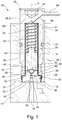
- is a cross-section view through a pressure control valve according to an embodiment of the invention;
- Fig. 2
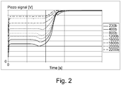
- is a graph (voltage vs. time) showing the response of the piezo-resistive element at different rail pressures.
- In the description below, the terms "top, bottom, above, below" will be used with reference to the orientation in the figures for ease of explanation.
- An embodiment of the present pressure control valve will now be described in an application as pressure limiting valve in a fuel accumulator (or common rail) of an injection system for an internal combustion engine, in particular a diesel engine.
- Although not shown, a common rail conventionally comprises an elongated tubular body and a longitudinal through bore defining an inner volume receiving, in use, high pressure fuel. The body is provided with a cavity at both extremities that are in fluid communication with the longitudinal bore. Externally, the rail is conventionally provided with protrusions distributed along the length of the rail body between the extremities. Each of the protrusions has a radially extending high pressure channel, not shown, adapted to flow high pressure fuel either entering the rail or exiting the rail towards fuel injectors.
- In
Fig.1 only the extremity of the common rail is shown, where such cavity is indicated at 12. The cavity 12 is cylindrical and comprises alateral wall 16 and abottom face 18. The upper region of cavity 12 is provided with a threadedsection 20 for screwing thepressure control valve 10 therein. Achannel 22 opens laterally in the lower cavity region to provide a return flow path from the cavity to the low pressure circuit of the injection system. Anopening 24 is arranged in thebottom face 18 to enable fluid communication with the longitudinal through bore of the common rail, which is filled in use with high-pressure fuel. It may be noted here that in the shown embodiment,reference sign 15 designates a transition bore that opens at one end into the cavity 12 throughorifice 24, and at the other end is in communication with the longitudinal through bore (not represented). Typically such transition bore 15 has a diameter lower than the longitudinal bore. Alternatively, the longitudinal through bore of the common rail could open directly into the cavity. The cavity 12 is sealed from the exterior by an annular joint 37. - The
pressure control valve 10 comprises ahousing 26 with a front region 26.1, engaged into cavity 12 and a base region 26.2.Housing 26 includes a metallic, cylindrical housing body 28 that extends along a longitudinal axis A and comprises aninternal cavity 30, which is closed towards the base region 26.2. Acompression spring 29 and apiston 31 are arranged inside thecavity 30, with the compression spring being compressed between the cavity bottom and thepiston 31. Towards the front region,internal cavity 30 is sealed by aseat ring 32 of thecontrol valve 10. The seat ring has a disk-like body portion 34 with a narrowercylindrical extension 36. Thebody portion 34 fits in an inlet section of the housing body 28 and rests with its annularinner side 38 against ashoulder 39 of the body 28. Thecylindrical extension 36 ofseat ring 32 extends further inside cavity 12. Theseat ring 32 is fixed in place in the housing body 28. It is e.g. maintained by the peripheral edge of body 28. - The
body portion 34 ofseat ring 32 has afront side 40, oppositeinner side 38 that forms the end face of thepressure control valve 10. In use, the control valve is positioned with the front region 26.1 screwed in cavity 12, thefront side 40 being pressed against thebottom face 18 of cavity 12, as represented inFig.1 . Anouter thread 41 is provided at the outer periphery of the front housing region 26.1, proximal to the base portion. The base portion may comprise a male or female drive configuration, here e.g. asocket head 43 for a Torx wrench or the like. - In the mounted position, a part of the
front side 40, referred to asannular contact surface 54, presses against a corresponding portion of thebottom face 18, referred to asannular sealing surface 56. This forms an annular barrier preventing fluid flow along thefront side 40 towards the cavity interior. The efficiency of the seal provided by the barrier depends on the screwing strength. - The pressure control function is achieved by way of a check valve formed in a
fluid passage 42 provided in thehousing 26. Thefluid passage 42 extends from aninlet port 44, centrally arranged infront side 40, to a pair ofoutlet ports 46 located in the housing body 28 and thus opening radially/laterally into the cavity 12. - A
valve seat 48 is arranged in thefluid passage 42, namely at the inner end of an inlet section 42.1 of thefluid passage 42 opening in the inner end face of thecylindrical extension 36. Thevalve seat 48 is formed as an annular sealing surface surrounding the end of inlet section 42.1; it may have has a spherical or conical cross-section, although other shapes are possible.Reference sign 50 designates a ball-shaped valve element that cooperates withvalve seat 48 to control the flow through the latter. Thevalve element 50 is biased in the closed position by thecompression spring 29 viapiston 31. Thevalve element 50 is here free, but could be attached at the tip ofpiston 31.Spring 29 has a predetermined spring force that is chosen so that thevalve element 50 lifts from itsseat 48 when the fuel pressure in the inlet section 42.1 offluid passage 42 exceeds a predetermined pressure threshold, acting as safety feature to relieve the excess fuel pressure from the fuel rail.Valve element 50 is thus moveable between a closed position, shown inFig.1 , wherein it sealingly rests on thevalve seat 48 and impedes the flow of fluid downstream thereof, and an open position in which the valve element is off the seat and allows fluid flow therethrough (when the pressure in inlet section 42.1 exceeds the predetermined pressure threshold). The general design and operation of such pressure limiting valve is known in the art and need not be described in further details. - It shall be appreciated that a piezo-
resistive element 52 is arranged on thevalve seat 48. The piezo-resisitive element 52 is a layer of piezo-resisitive material that entirely covers the annular sealing surface of thevalve seat 48. - When the
valve element 50 is in its closed position, the piezo-resistive element 52 is thus sandwiched between thevalve element 50 and thevalve seat 48. An electrical link is provided to apply a predetermined voltage to the piezo-resistive element 52, whereas the lower side of the piezo-resistive element 52is in contact with theseat ring 32, which is in turn in contact with thebottom face 18 of the common rail cavity, which is at ground potential. Such electrical link can be provided by an insulated wire, schematically indicated 58 inFig.1 , drawn through the housing, e.g. though the housing body 28, and connected to acontact washer 62 located at the bottom of theinternal cavity 30. An improved contact between thewire 58 andcontact washer 62 cab ne ensured by means of a contact spring (not shown) arranged in the body 28. It may be noted here that contact washers of different thicknesses may be used to adjust the initial load on thespring 29. Thewire 58 is connected at its other end to a contact terminal (not shown) in aconnector portion 60. The electrical link is then provided through thespring 29, thepiston 31 and thevalve element 50 in series. This is possible as all the parts in the housing 12 are typically made of metallic or otherwise electrically conductive material. - The provision of the piezo-
resistive element 52 at this interface allows measuring the force or contact pressure exerted by thevalve element 50 onto thevalve seat 48. This piezo-resistive element 52 can thus be used for measuring the initial pressure load applied by thecompression spring 29 to thevalve element 48 via thepiston 31. This initial pressure load is in fact the force exerted by the spring upon assembly. - The benefit of the piezo-
resistive element 52 is thus to generate a measure signal that depends on the contact pressure at the interface valve element 50 -valve seat 48. It suffices to apply a voltage to the piezo-resistive element 52 to check the pressure force during assembly. Testing of the opening pressure with high pressure fluid is no longer necessary. Additionally, in use, the contact pressure will vary depending on the fuel pressure in the common rail (in the longitudinal through bore). Indeed, the fuel pressure exerts a pressure force on thevalve element 50 in thepressure control valve 10, thus in the opening direction of thevalve member 50. When the fuel pressure in the longitudinal bore increases, the pressure in inlet section 42.1 also increases, and so does the force exerted by the fuel on thevalve element 50. This leads to a corresponding decrease of the contact pressure between thevalve element 50 and thevalve seat 48. The increase of pressure in the fuel rail thus causes a decrease of the contact pressure, which can be monitored by means of thepiezo element 52, the internal resistance of which will increase due to the decrease of compressive force. - The piezo-
resistive element 52 may typically be a piezo-resistive film or coating that is applied onto thecontact surface 54 at the front of theseat ring 32. It can be single or multi-layered. Any kind of appropriate piezo-resistive technology can be used, allowing to measurement of contact pressure/forces. Such force-sensing piezo electric films are known in the art. One example is a hydrocarbon film known as DiaForce® and developed by the Fraunhofer Institute for Manufacturing Technology and Advanced Materials (Brement, Germany). - With such piezo-resistive pressure sensor able to measure static forces one can thus determine, by way of the measure of the voltage through the piezo-
resistive element 52, the contact force at the interface between thevalve element 50 and thevalve seat 48. To avoid short-circuits, as shown inFig. 1 thehousing 26 comprises advantageously an insulating coating orsheeting 64. Thecoating 64 is disposed over the longitudinal wall of theinternal cavity 30 and between thehousing 26 and theseat ring 32. The spring, piston and seat ring are thus electrically insulated from the housing body. Insulatingsheating 62 is also provided at the bottom ofcavity 30 to insulate the contact washer from the body 28. -
Fig. 2 shows a graph (voltage vs. time) illustrating the response of the piezo element for several fuel rail pressures. The piezo element has a known resistance when its is not subject to any compressive force; and its resistance decreases when a compressive force is applied thereto. When readingFig.2 , one must keep in mind that when the fuel rail pressure increases, the contact pressure between thevalve element 50 and thevalve seat 48 decreases, i.e. the compressive force on the piezo element decreases against the bias of thecompression spring 29. As can be observed fromFig.2 , the change of resistance due to the change of fuel rail pressure does indeed lead to a significant change of voltage that can be properly detected, occuring over several volts for the pressure range over about 2200 bars. Since the resistance of the piezo element increases due to the reduction of pressure thereon, the voltage signal also increases.
Claims (12)
- A fuel injection component for a fuel injection system, said fuel injection component comprising a pressure control valve (10) disposed in a cavity (12) in said component between a high pressure side and a low pressure side, said cavity comprising a cylindrical wall (16), a bottom wall (18), a high pressure inlet opening (24) in said a bottom wall and a low pressure outlet opening (22);
wherein said pressure control valve comprises a housing (26) including a fluid channel (42) extending between an inlet port (44) and an outlet port (46), a valve seat (48) in said fluid channel, and a valve element (50) associated with said valve seat to open or close fluid flow therethrough, as well as means (29) for biasing the valve member onto its valve seat;
wherein said housing has an external, annular contact surface (54) that is adapted to be pressed against a corresponding annular sealing surface (56) in said cavity, said annular contact surface (54) separating the region of the inlet port (44), in communication with said high pressure inlet opening (24), from that of the outlet port (46), in communication with said low pressure outlet opening (22);
wherein a piezo-resistive element (52) is arranged on said valve seat, the internal resistance of said piezo-resistive element depending on the pressure applied thereon, thereby enabling sensing a contact pressure of said valve element against said valve seat. - The fuel injection component according to claim 1, wherein an electrical link is provided in said housing to apply a voltage to said piezo-resistive element, in particular from a connector terminal.
- The fuel injection component according to claim 1 or 2, wherein said piezo-resistive element is a piezo-resistive film or coating.
- The fuel injection component according to any one of the preceding claims, wherein
said housing comprises a cylindrical housing body (28) with an internal cavity (30) that is closed at a front end by a seat ring (32), said seat ring having an inner side turned towards said internal cavity and an opposite outer side (40) forming a front end face; and
said inlet port (44) and valve seat (48) are arranged in said seat ring, an inlet section (42.1) of said fluid passage extending in said seat ring between said inlet port and valve seat. - The fuel injection component according to any one of the preceding claims, wherein said housing includes a base housing part (26.2) and a front housing part (26.1) engaged into said cavity (12), said front housing part extending along a longitudinal axis (X), said housing further including fastening means (41) for fixing of the valve into said cavity (12); and
wherein said inlet port (44) is located in said front housing part as well as said external, annular contact surface (54) that is pressed against said corresponding annular sealing surface (56) in said cavity. - The fuel injection component according to any one of the preceding claims, wherein said inlet port is located in a front end face of said front housing part; and
said annular contact surface is part of said front end face and surrounds said inlet port. - The fuel injection component according to any one of the preceding claims, wherein said valve member is biased on said valve seat by a compression spring (39), and preferably, said compression spring acts upon an axially guided piston (31), which in turn acts upon said valve member.
- The fuel injection component according to claim 7, wherein said electrical link comprises a wire (58) connected at one end to a connector terminal and connected at the other end to said spring in said internal cavity, thereby enabling current flow to said valve member via said spring and piston.
- The fuel injection component according to any one claims 1 to 6, wherein said pressure control valve comprises an electromagnetic actuator including:a pin axially moveable in said cavity, said pin being coupled at one end to said valve member and at the other end attached to an armature;an electromagnet adapted to create a magnetic field to move said armature in a first direction; andwherein said compression spring is arranged so as to bias said pin in the direction of said valve seat.
- The fuel injection component according to any one of the preceding claims, wherein an insulating sheeting or coating (64) is provided on the wall of said internal cavity.
- The fuel injection component to anyone of the preceding claims, wherein said housing comprises an outer thread (41) that cooperates with a corresponding thread (20) in said cavity for fixing said valve therein by screwing in said longitudinal direction.
- The fuel injection component according to any one of the preceding claims, wherein said fuel injection component is a common rail or a fuel pump.
Applications Claiming Priority (1)
| Application Number | Priority Date | Filing Date | Title |
|---|---|---|---|
| GB1812526.0A GB2576147B (en) | 2018-08-01 | 2018-08-01 | Pressure control valve for a fuel injection system |
Publications (1)
| Publication Number | Publication Date |
|---|---|
| EP3604789A1 true EP3604789A1 (en) | 2020-02-05 |
Family
ID=63518263
Family Applications (1)
| Application Number | Title | Priority Date | Filing Date |
|---|---|---|---|
| EP19184520.5A Withdrawn EP3604789A1 (en) | 2018-08-01 | 2019-07-04 | Pressure control valve for a fuel injection system |
Country Status (2)
| Country | Link |
|---|---|
| EP (1) | EP3604789A1 (en) |
| GB (1) | GB2576147B (en) |
Citations (3)
| Publication number | Priority date | Publication date | Assignee | Title |
|---|---|---|---|---|
| EP1826394A2 (en) * | 2006-02-27 | 2007-08-29 | Denso Corporation | Electromagnetic actuator performing quick response |
| DE102011016168A1 (en) * | 2011-04-05 | 2012-10-11 | L'orange Gmbh | Fuel injector for internal combustion engine, has nozzle body, within which valve needle of valve of fuel injector is longitudinal displaceably received, where valve partner is formed in form of valve seat of valve |
| DE102016220461A1 (en) * | 2016-10-19 | 2018-04-19 | Robert Bosch Gmbh | Method for determining the pressure in a combustion chamber of an internal combustion engine, fuel injector |
Family Cites Families (1)
| Publication number | Priority date | Publication date | Assignee | Title |
|---|---|---|---|---|
| GB201511007D0 (en) * | 2015-06-23 | 2015-08-05 | Delphi Int Operations Lux Srl | Nozzle assembly with adaptive closed signal |
-
2018
- 2018-08-01 GB GB1812526.0A patent/GB2576147B/en active Active
-
2019
- 2019-07-04 EP EP19184520.5A patent/EP3604789A1/en not_active Withdrawn
Patent Citations (3)
| Publication number | Priority date | Publication date | Assignee | Title |
|---|---|---|---|---|
| EP1826394A2 (en) * | 2006-02-27 | 2007-08-29 | Denso Corporation | Electromagnetic actuator performing quick response |
| DE102011016168A1 (en) * | 2011-04-05 | 2012-10-11 | L'orange Gmbh | Fuel injector for internal combustion engine, has nozzle body, within which valve needle of valve of fuel injector is longitudinal displaceably received, where valve partner is formed in form of valve seat of valve |
| DE102016220461A1 (en) * | 2016-10-19 | 2018-04-19 | Robert Bosch Gmbh | Method for determining the pressure in a combustion chamber of an internal combustion engine, fuel injector |
Also Published As
| Publication number | Publication date |
|---|---|
| GB2576147B (en) | 2021-03-24 |
| GB2576147A (en) | 2020-02-12 |
| GB201812526D0 (en) | 2018-09-12 |
Similar Documents
| Publication | Publication Date | Title |
|---|---|---|
| US6420817B1 (en) | Method for detecting injection events in a piezoelectric actuated fuel injector | |
| US6929192B2 (en) | Valve for controlling fluids and method for measuring pressures | |
| US6298731B1 (en) | Combination pressure sensor and regulator for direct injection engine fuel system | |
| US4183467A (en) | Fluid control valves | |
| US8224554B2 (en) | Fuel injector with built-in fuel pressure sensor | |
| US6345606B1 (en) | Method for controlling fuel rail pressure using a piezoelectric actuated fuel injector | |
| US6318342B1 (en) | Fuel injection valve and pressure sensor combination | |
| US8365705B2 (en) | Fuel injection valve | |
| US7918128B2 (en) | Fuel injector with electric shield | |
| US7931009B2 (en) | Fuel injector designed to minimize mechanical stress on fuel pressure sensor installed therein | |
| US20100263633A1 (en) | Fuel injection valve and fuel injection apparatus | |
| US7055762B2 (en) | Injection valve with a capacitive valve lift sensor | |
| CN101016950A (en) | Solenoid valve | |
| EP0304199B1 (en) | Fuel injection nozzle | |
| US6807950B2 (en) | Fuel injection device for internal combustion engine | |
| GB2576147A (en) | Pressure control valve for a fuel injection system | |
| US6752333B2 (en) | Fuel injection valve | |
| EP3604788A1 (en) | Pressure control valve for a fuel injection system | |
| EP3734248B1 (en) | A high-pressure hydraulic system comprising a sensor for non-invasive diagnostics | |
| US20110006137A1 (en) | Sealed electric feedthrough | |
| US11384722B2 (en) | Injector closed loop control | |
| JP2000161176A (en) | Piezoelectric control valve | |
| EP1136694A2 (en) | Condition sensor for a fuel injector | |
| US20180355817A1 (en) | Fuel injection system, fuel injection method and automobile | |
| GB2170554A (en) | I.C. engine fuel injection nozzle lift sensors |
Legal Events
| Date | Code | Title | Description |
|---|---|---|---|
| PUAI | Public reference made under article 153(3) epc to a published international application that has entered the european phase |
Free format text: ORIGINAL CODE: 0009012 |
|
| AK | Designated contracting states |
Kind code of ref document: A1 Designated state(s): AL AT BE BG CH CY CZ DE DK EE ES FI FR GB GR HR HU IE IS IT LI LT LU LV MC MK MT NL NO PL PT RO RS SE SI SK SM TR |
|
| STAA | Information on the status of an ep patent application or granted ep patent |
Free format text: STATUS: THE APPLICATION IS DEEMED TO BE WITHDRAWN |
|
| 18D | Application deemed to be withdrawn |
Effective date: 20200608 |