EP3604775A1 - Engine control device for vehicle - Google Patents
Engine control device for vehicle Download PDFInfo
- Publication number
- EP3604775A1 EP3604775A1 EP18770904.3A EP18770904A EP3604775A1 EP 3604775 A1 EP3604775 A1 EP 3604775A1 EP 18770904 A EP18770904 A EP 18770904A EP 3604775 A1 EP3604775 A1 EP 3604775A1
- Authority
- EP
- European Patent Office
- Prior art keywords
- engine
- speed
- vehicle
- centrifugal clutch
- control
- Prior art date
- Legal status (The legal status is an assumption and is not a legal conclusion. Google has not performed a legal analysis and makes no representation as to the accuracy of the status listed.)
- Granted
Links
Images


Classifications
-
- B—PERFORMING OPERATIONS; TRANSPORTING
- B60—VEHICLES IN GENERAL
- B60W—CONJOINT CONTROL OF VEHICLE SUB-UNITS OF DIFFERENT TYPE OR DIFFERENT FUNCTION; CONTROL SYSTEMS SPECIALLY ADAPTED FOR HYBRID VEHICLES; ROAD VEHICLE DRIVE CONTROL SYSTEMS FOR PURPOSES NOT RELATED TO THE CONTROL OF A PARTICULAR SUB-UNIT
- B60W20/00—Control systems specially adapted for hybrid vehicles
- B60W20/40—Controlling the engagement or disengagement of prime movers, e.g. for transition between prime movers
-
- F—MECHANICAL ENGINEERING; LIGHTING; HEATING; WEAPONS; BLASTING
- F02—COMBUSTION ENGINES; HOT-GAS OR COMBUSTION-PRODUCT ENGINE PLANTS
- F02D—CONTROLLING COMBUSTION ENGINES
- F02D41/00—Electrical control of supply of combustible mixture or its constituents
- F02D41/02—Circuit arrangements for generating control signals
- F02D41/04—Introducing corrections for particular operating conditions
- F02D41/12—Introducing corrections for particular operating conditions for deceleration
- F02D41/123—Introducing corrections for particular operating conditions for deceleration the fuel injection being cut-off
-
- B—PERFORMING OPERATIONS; TRANSPORTING
- B60—VEHICLES IN GENERAL
- B60K—ARRANGEMENT OR MOUNTING OF PROPULSION UNITS OR OF TRANSMISSIONS IN VEHICLES; ARRANGEMENT OR MOUNTING OF PLURAL DIVERSE PRIME-MOVERS IN VEHICLES; AUXILIARY DRIVES FOR VEHICLES; INSTRUMENTATION OR DASHBOARDS FOR VEHICLES; ARRANGEMENTS IN CONNECTION WITH COOLING, AIR INTAKE, GAS EXHAUST OR FUEL SUPPLY OF PROPULSION UNITS IN VEHICLES
- B60K17/00—Arrangement or mounting of transmissions in vehicles
- B60K17/02—Arrangement or mounting of transmissions in vehicles characterised by arrangement, location, or kind of clutch
-
- B—PERFORMING OPERATIONS; TRANSPORTING
- B60—VEHICLES IN GENERAL
- B60K—ARRANGEMENT OR MOUNTING OF PROPULSION UNITS OR OF TRANSMISSIONS IN VEHICLES; ARRANGEMENT OR MOUNTING OF PLURAL DIVERSE PRIME-MOVERS IN VEHICLES; AUXILIARY DRIVES FOR VEHICLES; INSTRUMENTATION OR DASHBOARDS FOR VEHICLES; ARRANGEMENTS IN CONNECTION WITH COOLING, AIR INTAKE, GAS EXHAUST OR FUEL SUPPLY OF PROPULSION UNITS IN VEHICLES
- B60K6/00—Arrangement or mounting of plural diverse prime-movers for mutual or common propulsion, e.g. hybrid propulsion systems comprising electric motors and internal combustion engines
- B60K6/20—Arrangement or mounting of plural diverse prime-movers for mutual or common propulsion, e.g. hybrid propulsion systems comprising electric motors and internal combustion engines the prime-movers consisting of electric motors and internal combustion engines, e.g. HEVs
- B60K6/22—Arrangement or mounting of plural diverse prime-movers for mutual or common propulsion, e.g. hybrid propulsion systems comprising electric motors and internal combustion engines the prime-movers consisting of electric motors and internal combustion engines, e.g. HEVs characterised by apparatus, components or means specially adapted for HEVs
- B60K6/38—Arrangement or mounting of plural diverse prime-movers for mutual or common propulsion, e.g. hybrid propulsion systems comprising electric motors and internal combustion engines the prime-movers consisting of electric motors and internal combustion engines, e.g. HEVs characterised by apparatus, components or means specially adapted for HEVs characterised by the driveline clutches
-
- B—PERFORMING OPERATIONS; TRANSPORTING
- B60—VEHICLES IN GENERAL
- B60K—ARRANGEMENT OR MOUNTING OF PROPULSION UNITS OR OF TRANSMISSIONS IN VEHICLES; ARRANGEMENT OR MOUNTING OF PLURAL DIVERSE PRIME-MOVERS IN VEHICLES; AUXILIARY DRIVES FOR VEHICLES; INSTRUMENTATION OR DASHBOARDS FOR VEHICLES; ARRANGEMENTS IN CONNECTION WITH COOLING, AIR INTAKE, GAS EXHAUST OR FUEL SUPPLY OF PROPULSION UNITS IN VEHICLES
- B60K6/00—Arrangement or mounting of plural diverse prime-movers for mutual or common propulsion, e.g. hybrid propulsion systems comprising electric motors and internal combustion engines
- B60K6/20—Arrangement or mounting of plural diverse prime-movers for mutual or common propulsion, e.g. hybrid propulsion systems comprising electric motors and internal combustion engines the prime-movers consisting of electric motors and internal combustion engines, e.g. HEVs
- B60K6/42—Arrangement or mounting of plural diverse prime-movers for mutual or common propulsion, e.g. hybrid propulsion systems comprising electric motors and internal combustion engines the prime-movers consisting of electric motors and internal combustion engines, e.g. HEVs characterised by the architecture of the hybrid electric vehicle
- B60K6/48—Parallel type
- B60K6/485—Motor-assist type
-
- B—PERFORMING OPERATIONS; TRANSPORTING
- B60—VEHICLES IN GENERAL
- B60W—CONJOINT CONTROL OF VEHICLE SUB-UNITS OF DIFFERENT TYPE OR DIFFERENT FUNCTION; CONTROL SYSTEMS SPECIALLY ADAPTED FOR HYBRID VEHICLES; ROAD VEHICLE DRIVE CONTROL SYSTEMS FOR PURPOSES NOT RELATED TO THE CONTROL OF A PARTICULAR SUB-UNIT
- B60W10/00—Conjoint control of vehicle sub-units of different type or different function
- B60W10/04—Conjoint control of vehicle sub-units of different type or different function including control of propulsion units
- B60W10/06—Conjoint control of vehicle sub-units of different type or different function including control of propulsion units including control of combustion engines
-
- B—PERFORMING OPERATIONS; TRANSPORTING
- B60—VEHICLES IN GENERAL
- B60W—CONJOINT CONTROL OF VEHICLE SUB-UNITS OF DIFFERENT TYPE OR DIFFERENT FUNCTION; CONTROL SYSTEMS SPECIALLY ADAPTED FOR HYBRID VEHICLES; ROAD VEHICLE DRIVE CONTROL SYSTEMS FOR PURPOSES NOT RELATED TO THE CONTROL OF A PARTICULAR SUB-UNIT
- B60W10/00—Conjoint control of vehicle sub-units of different type or different function
- B60W10/04—Conjoint control of vehicle sub-units of different type or different function including control of propulsion units
- B60W10/08—Conjoint control of vehicle sub-units of different type or different function including control of propulsion units including control of electric propulsion units, e.g. motors or generators
-
- B—PERFORMING OPERATIONS; TRANSPORTING
- B60—VEHICLES IN GENERAL
- B60W—CONJOINT CONTROL OF VEHICLE SUB-UNITS OF DIFFERENT TYPE OR DIFFERENT FUNCTION; CONTROL SYSTEMS SPECIALLY ADAPTED FOR HYBRID VEHICLES; ROAD VEHICLE DRIVE CONTROL SYSTEMS FOR PURPOSES NOT RELATED TO THE CONTROL OF A PARTICULAR SUB-UNIT
- B60W20/00—Control systems specially adapted for hybrid vehicles
- B60W20/10—Controlling the power contribution of each of the prime movers to meet required power demand
- B60W20/15—Control strategies specially adapted for achieving a particular effect
- B60W20/19—Control strategies specially adapted for achieving a particular effect for achieving enhanced acceleration
-
- B—PERFORMING OPERATIONS; TRANSPORTING
- B60—VEHICLES IN GENERAL
- B60W—CONJOINT CONTROL OF VEHICLE SUB-UNITS OF DIFFERENT TYPE OR DIFFERENT FUNCTION; CONTROL SYSTEMS SPECIALLY ADAPTED FOR HYBRID VEHICLES; ROAD VEHICLE DRIVE CONTROL SYSTEMS FOR PURPOSES NOT RELATED TO THE CONTROL OF A PARTICULAR SUB-UNIT
- B60W50/00—Details of control systems for road vehicle drive control not related to the control of a particular sub-unit, e.g. process diagnostic or vehicle driver interfaces
- B60W50/06—Improving the dynamic response of the control system, e.g. improving the speed of regulation or avoiding hunting or overshoot
-
- F—MECHANICAL ENGINEERING; LIGHTING; HEATING; WEAPONS; BLASTING
- F02—COMBUSTION ENGINES; HOT-GAS OR COMBUSTION-PRODUCT ENGINE PLANTS
- F02D—CONTROLLING COMBUSTION ENGINES
- F02D41/00—Electrical control of supply of combustible mixture or its constituents
- F02D41/02—Circuit arrangements for generating control signals
- F02D41/021—Introducing corrections for particular conditions exterior to the engine
- F02D41/0215—Introducing corrections for particular conditions exterior to the engine in relation with elements of the transmission
- F02D41/022—Introducing corrections for particular conditions exterior to the engine in relation with elements of the transmission in relation with the clutch status
-
- F—MECHANICAL ENGINEERING; LIGHTING; HEATING; WEAPONS; BLASTING
- F02—COMBUSTION ENGINES; HOT-GAS OR COMBUSTION-PRODUCT ENGINE PLANTS
- F02D—CONTROLLING COMBUSTION ENGINES
- F02D41/00—Electrical control of supply of combustible mixture or its constituents
- F02D41/02—Circuit arrangements for generating control signals
- F02D41/04—Introducing corrections for particular operating conditions
- F02D41/08—Introducing corrections for particular operating conditions for idling
-
- F—MECHANICAL ENGINEERING; LIGHTING; HEATING; WEAPONS; BLASTING
- F02—COMBUSTION ENGINES; HOT-GAS OR COMBUSTION-PRODUCT ENGINE PLANTS
- F02N—STARTING OF COMBUSTION ENGINES; STARTING AIDS FOR SUCH ENGINES, NOT OTHERWISE PROVIDED FOR
- F02N11/00—Starting of engines by means of electric motors
- F02N11/08—Circuits specially adapted for starting of engines
- F02N11/0814—Circuits specially adapted for starting of engines comprising means for controlling automatic idle-start-stop
- F02N11/0844—Circuits specially adapted for starting of engines comprising means for controlling automatic idle-start-stop with means for restarting the engine directly after an engine stop request, e.g. caused by change of driver mind
-
- F—MECHANICAL ENGINEERING; LIGHTING; HEATING; WEAPONS; BLASTING
- F16—ENGINEERING ELEMENTS AND UNITS; GENERAL MEASURES FOR PRODUCING AND MAINTAINING EFFECTIVE FUNCTIONING OF MACHINES OR INSTALLATIONS; THERMAL INSULATION IN GENERAL
- F16H—GEARING
- F16H45/00—Combinations of fluid gearings for conveying rotary motion with couplings or clutches
- F16H45/02—Combinations of fluid gearings for conveying rotary motion with couplings or clutches with mechanical clutches for bridging a fluid gearing of the hydrokinetic type
-
- B—PERFORMING OPERATIONS; TRANSPORTING
- B60—VEHICLES IN GENERAL
- B60K—ARRANGEMENT OR MOUNTING OF PROPULSION UNITS OR OF TRANSMISSIONS IN VEHICLES; ARRANGEMENT OR MOUNTING OF PLURAL DIVERSE PRIME-MOVERS IN VEHICLES; AUXILIARY DRIVES FOR VEHICLES; INSTRUMENTATION OR DASHBOARDS FOR VEHICLES; ARRANGEMENTS IN CONNECTION WITH COOLING, AIR INTAKE, GAS EXHAUST OR FUEL SUPPLY OF PROPULSION UNITS IN VEHICLES
- B60K15/00—Arrangement in connection with fuel supply of combustion engines or other fuel consuming energy converters, e.g. fuel cells; Mounting or construction of fuel tanks
- B60K15/03—Fuel tanks
- B60K2015/0319—Fuel tanks with electronic systems, e.g. for controlling fuelling or venting
-
- B—PERFORMING OPERATIONS; TRANSPORTING
- B60—VEHICLES IN GENERAL
- B60W—CONJOINT CONTROL OF VEHICLE SUB-UNITS OF DIFFERENT TYPE OR DIFFERENT FUNCTION; CONTROL SYSTEMS SPECIALLY ADAPTED FOR HYBRID VEHICLES; ROAD VEHICLE DRIVE CONTROL SYSTEMS FOR PURPOSES NOT RELATED TO THE CONTROL OF A PARTICULAR SUB-UNIT
- B60W2300/00—Indexing codes relating to the type of vehicle
- B60W2300/36—Cycles; Motorcycles; Scooters
-
- B—PERFORMING OPERATIONS; TRANSPORTING
- B60—VEHICLES IN GENERAL
- B60W—CONJOINT CONTROL OF VEHICLE SUB-UNITS OF DIFFERENT TYPE OR DIFFERENT FUNCTION; CONTROL SYSTEMS SPECIALLY ADAPTED FOR HYBRID VEHICLES; ROAD VEHICLE DRIVE CONTROL SYSTEMS FOR PURPOSES NOT RELATED TO THE CONTROL OF A PARTICULAR SUB-UNIT
- B60W2510/00—Input parameters relating to a particular sub-units
- B60W2510/02—Clutches
- B60W2510/0208—Clutch engagement state, e.g. engaged or disengaged
- B60W2510/0216—Clutch engagement rate
-
- B—PERFORMING OPERATIONS; TRANSPORTING
- B60—VEHICLES IN GENERAL
- B60W—CONJOINT CONTROL OF VEHICLE SUB-UNITS OF DIFFERENT TYPE OR DIFFERENT FUNCTION; CONTROL SYSTEMS SPECIALLY ADAPTED FOR HYBRID VEHICLES; ROAD VEHICLE DRIVE CONTROL SYSTEMS FOR PURPOSES NOT RELATED TO THE CONTROL OF A PARTICULAR SUB-UNIT
- B60W2510/00—Input parameters relating to a particular sub-units
- B60W2510/06—Combustion engines, Gas turbines
- B60W2510/0638—Engine speed
-
- B—PERFORMING OPERATIONS; TRANSPORTING
- B60—VEHICLES IN GENERAL
- B60W—CONJOINT CONTROL OF VEHICLE SUB-UNITS OF DIFFERENT TYPE OR DIFFERENT FUNCTION; CONTROL SYSTEMS SPECIALLY ADAPTED FOR HYBRID VEHICLES; ROAD VEHICLE DRIVE CONTROL SYSTEMS FOR PURPOSES NOT RELATED TO THE CONTROL OF A PARTICULAR SUB-UNIT
- B60W2540/00—Input parameters relating to occupants
- B60W2540/10—Accelerator pedal position
-
- F—MECHANICAL ENGINEERING; LIGHTING; HEATING; WEAPONS; BLASTING
- F02—COMBUSTION ENGINES; HOT-GAS OR COMBUSTION-PRODUCT ENGINE PLANTS
- F02D—CONTROLLING COMBUSTION ENGINES
- F02D2250/00—Engine control related to specific problems or objectives
- F02D2250/18—Control of the engine output torque
- F02D2250/24—Control of the engine output torque by using an external load, e.g. a generator
-
- F—MECHANICAL ENGINEERING; LIGHTING; HEATING; WEAPONS; BLASTING
- F02—COMBUSTION ENGINES; HOT-GAS OR COMBUSTION-PRODUCT ENGINE PLANTS
- F02N—STARTING OF COMBUSTION ENGINES; STARTING AIDS FOR SUCH ENGINES, NOT OTHERWISE PROVIDED FOR
- F02N11/00—Starting of engines by means of electric motors
- F02N11/04—Starting of engines by means of electric motors the motors being associated with current generators
-
- F—MECHANICAL ENGINEERING; LIGHTING; HEATING; WEAPONS; BLASTING
- F02—COMBUSTION ENGINES; HOT-GAS OR COMBUSTION-PRODUCT ENGINE PLANTS
- F02N—STARTING OF COMBUSTION ENGINES; STARTING AIDS FOR SUCH ENGINES, NOT OTHERWISE PROVIDED FOR
- F02N2200/00—Parameters used for control of starting apparatus
- F02N2200/02—Parameters used for control of starting apparatus said parameters being related to the engine
- F02N2200/022—Engine speed
-
- F—MECHANICAL ENGINEERING; LIGHTING; HEATING; WEAPONS; BLASTING
- F02—COMBUSTION ENGINES; HOT-GAS OR COMBUSTION-PRODUCT ENGINE PLANTS
- F02N—STARTING OF COMBUSTION ENGINES; STARTING AIDS FOR SUCH ENGINES, NOT OTHERWISE PROVIDED FOR
- F02N99/00—Subject matter not provided for in the other groups of this subclass
- F02N99/002—Starting combustion engines by ignition means
- F02N99/006—Providing a combustible mixture inside the cylinder
-
- F—MECHANICAL ENGINEERING; LIGHTING; HEATING; WEAPONS; BLASTING
- F16—ENGINEERING ELEMENTS AND UNITS; GENERAL MEASURES FOR PRODUCING AND MAINTAINING EFFECTIVE FUNCTIONING OF MACHINES OR INSTALLATIONS; THERMAL INSULATION IN GENERAL
- F16H—GEARING
- F16H59/00—Control inputs to control units of change-speed- or reversing-gearings for conveying rotary motion
- F16H59/36—Inputs being a function of speed
- F16H2059/366—Engine or motor speed
-
- F—MECHANICAL ENGINEERING; LIGHTING; HEATING; WEAPONS; BLASTING
- F16—ENGINEERING ELEMENTS AND UNITS; GENERAL MEASURES FOR PRODUCING AND MAINTAINING EFFECTIVE FUNCTIONING OF MACHINES OR INSTALLATIONS; THERMAL INSULATION IN GENERAL
- F16H—GEARING
- F16H61/00—Control functions within control units of change-speed- or reversing-gearings for conveying rotary motion ; Control of exclusively fluid gearing, friction gearing, gearings with endless flexible members or other particular types of gearing
- F16H2061/0015—Transmission control for optimising fuel consumptions
-
- H—ELECTRICITY
- H02—GENERATION; CONVERSION OR DISTRIBUTION OF ELECTRIC POWER
- H02P—CONTROL OR REGULATION OF ELECTRIC MOTORS, ELECTRIC GENERATORS OR DYNAMO-ELECTRIC CONVERTERS; CONTROLLING TRANSFORMERS, REACTORS OR CHOKE COILS
- H02P9/00—Arrangements for controlling electric generators for the purpose of obtaining a desired output
- H02P9/06—Control effected upon clutch or other mechanical power transmission means and dependent upon electric output value of the generator
-
- H—ELECTRICITY
- H02—GENERATION; CONVERSION OR DISTRIBUTION OF ELECTRIC POWER
- H02P—CONTROL OR REGULATION OF ELECTRIC MOTORS, ELECTRIC GENERATORS OR DYNAMO-ELECTRIC CONVERTERS; CONTROLLING TRANSFORMERS, REACTORS OR CHOKE COILS
- H02P9/00—Arrangements for controlling electric generators for the purpose of obtaining a desired output
- H02P9/48—Arrangements for obtaining a constant output value at varying speed of the generator, e.g. on vehicle
Definitions
- the present invention relates to an engine control device for a vehicle, and particularly to an engine control device for a vehicle applied to a vehicle in which a centrifugal clutch is used for connection and disconnection of engine driving force.
- Patent Literature 1 discloses an engine control device for a vehicle including a torque converter and a lockup clutch, which is configured such that, after fuel injection is stopped due to absence of an acceleration request, if the engine speed becomes lower than a predetermined value in a state in which the lockup clutch is connected, then fuel injection is restarted such that a lean combustion state is established, and after fuel injection is restarted, the lockup clutch is disconnected. According to this configuration, while torque variation is suppressed, engine stall can be prevented by lean combustion.
- Patent Document 1 JP 2001-98978 A
- the object of the present invention resides in provision of an engine control device for a saddle riding (saddled) vehicle that can solve the subject of the prior art described above and can improve the acceleration response from a state in which the engine speed is lower than an engine speed at which a centrifugal clutch is disconnected.
- an engine control device for a vehicle applied to a vehicle (1) includes a mechanical centrifugal clutch (C) for connecting and disconnecting driving force to be transmitted from an engine (E) to a driving wheel (WR), wherein the vehicle (1) includes a throttle operator (47) configured to adjust output power of the engine (E), a motor (8) configured to rotate a crankshaft (2) of the engine (E), and a control unit (100) configured to control the motor (8) and a fuel injection system (52), and the control unit (100) executes injection stopping control for stopping fuel injection during deceleration of the vehicle (1) and executes, when an opening operation of the throttle operator (47) is performed after an engine speed (Ne) becomes equal to or lower than a centrifugal clutch disconnection speed (Ne3) at which the centrifugal clutch (C) is disconnected, acceleration assist control for rotating the crankshaft (2) with the motor (8).
- a mechanical centrifugal clutch (C) for connecting and disconnecting driving force to be transmitted from an engine (E) to a driving wheel (WR)
- the present invention has a second feature in that when the engine speed (Ne) decreases to an injection restart speed (Ne2) that is lower than the centrifugal clutch disconnection speed (Ne3) after fuel injection by the injection stopping control stops, the control unit (100) causes the fuel injection to be restarted.
- the present invention has a third feature in that the injection restart speed (Ne2) at which the fuel injection is to be restarted is higher than an idle speed (Ne1).
- the present invention has a fourth feature in that when the engine (E) is caused to operate with an idle speed (Ne1), the control unit (100) executes idle assist control for causing the motor (8) to rotate the crankshaft (2).
- an engine control device for a vehicle applied to a vehicle (1) includes a mechanical centrifugal clutch (C) for connecting and disconnecting driving force to be transmitted from an engine (E) to a driving wheel (WR), wherein the vehicle (1) includes a throttle operator (47) configured to adjust output power of the engine (E), a motor (8) configured to rotate a crankshaft (2) of the engine (E), and a control unit (100) configured to control the motor (8) and a fuel injection system (52), the control unit (100) causes fuel injection to be stopped during deceleration of the vehicle (1) and executes, when an opening operation of the throttle operator (47) is performed after an engine speed (Ne) becomes equal to or lower than a centrifugal clutch disconnection speed (Ne3) at which the centrifugal clutch (C) is disconnected, acceleration assist control for causing the motor (8) to rotate the crankshaft (2), the control unit (100) executes, when the engine (E) is to
- an engine control device for a vehicle applied to a vehicle (1) includes a mechanical centrifugal clutch (C) for connecting and disconnecting driving force to be transmitted from an engine (E) to a driving wheel (WR), wherein the vehicle (1) includes a throttle operator (47) configured to adjust output power of the engine (E), a motor (8) configured to rotate a crankshaft (2) of the engine (E), and a control unit (100) configured to control the motor (8) and a fuel injection system (52), and the control unit (100) executes injection stopping control for stopping fuel injection during deceleration of the vehicle (1) and executes, when an opening operation of the throttle operator (47) is performed after an engine speed (Ne) becomes equal to or lower than a centrifugal clutch disconnection speed (Ne3) at which the centrifugal clutch (C) is disconnected, acceleration assist control for rotating the crankshaft (2) with the motor (8). Therefore, since fuel injection is stopped during deceleration of the vehicle, the fuel consumption can be suppressed and an acceleration delay in
- the vehicle is accelerated actually only after the centrifugal clutch is connected after the engine speed starts increase, and therefore, a delay is likely to occur in acceleration response to the opening operation of the throttle.
- the crankshaft is accelerated by the motor in response to an opening operation of the throttle, the time required until the centrifugal clutch is connected can be reduced to improve the acceleration response.
- the control unit (100) causes the fuel injection to be restarted. Therefore, the fuel consumption amount can be suppressed by elongating the stop period of fuel injection. Further, although it is necessary to restart injection in order to transit to idle operation after fuel injection is stopped upon deceleration, by executing the restart of fuel injection after the centrifugal clutch is disconnected, it is possible to transit to idle operation without having an influence on the driving force to be transmitted to the driving wheel.
- the injection restart speed (Ne2) at which the fuel injection is to be restarted is higher than an idle speed (Ne1). Therefore, even in the case where some ignition delay or the like occurs upon restart of injection, it is possible to transit to idle operation smoothly without causing such a situation that the engine speed becomes lower than the idle speed or engine stall occurs.
- the control unit (100) executes idle assist control for causing the motor (8) to rotate the crankshaft (2). Therefore, for example, by performing idle operation using both of fuel injection and idle assist control, it is possible to reduce the fuel consumption amount upon idle operation.
- an engine control device for a vehicle applied to a vehicle (1) includes a mechanical centrifugal clutch (C) for connecting and disconnecting driving force to be transmitted from an engine (E) to a driving wheel (WR), wherein the vehicle (1) includes a throttle operator (47) configured to adjust output power of the engine (E), a motor (8) configured to rotate a crankshaft (2) of the engine (E), and a control unit (100) configured to control the motor (8) and a fuel injection system (52), the control unit (100) causes fuel injection to be stopped during deceleration of the vehicle (1) and executes, when an opening operation of the throttle operator (47) is performed after an engine speed (Ne) becomes equal to or lower than a centrifugal clutch disconnection speed (Ne3) at which the centrifugal clutch (C) is disconnected, acceleration assist control for causing the motor (8) to rotate the crankshaft (2), the control unit (100) executes, when the engine (E) is to be caused to operate with an idle speed (Ne1), idle
- the fuel consumption can be suppressed, and an acceleration delay in the case where the throttle is operated for opening in a state in which the centrifugal clutch is disconnected can be reduced. Further, since idle operation is performed only with the motor driving force, after fuel injection is stopped once upon deceleration, there is no necessity to inject the fuel before restart of the vehicle, and the fuel consumption amount can be reduced further.
- FIG. 1 is a left side elevational view of a motorcycle 1 to which an engine control device for a vehicle according to an embodiment of the present invention is applied.
- the motorcycle 1 is a saddle riding (saddled) vehicle of the scooter type that includes a front wheel WF supported for steering movement by a steering handlebar 60, a rear wheel WR supported at a rear portion of a swing unit 70 that configures an engine E and a transmission integrally, and a seat 62 provided between the front wheel WF and the rear wheel WR such that a passenger is seated astride the seat 62.
- an alternating-current generating (ACG) starter motor 8 is attached which rotates the crankshaft 2 when power is supplied thereto and functions, after the engine E is started, as a generator. Further, the motorcycle 1 has an idle stop function of stopping the engine E if a predetermined stopping condition is satisfied and restarting the engine E if a predetermined restarting condition is satisfied.
- ACG alternating-current generating
- the motorcycle 1 includes a vehicle body frame 63, and a link mechanism 65 extends rearwardly of the vehicle from the vehicle body frame 63 through a link pivot 64 as a shaft member.
- the swing unit 70 is supported for rocking motion with respect to the vehicle body frame 63 by the link mechanism 65.
- the steering handlebar 60 is fixed to an upper end portion of a steering stem 69, and a pair of left and right front forks 71 for supporting the front wheel WF for rotation thereon is fixed to a lower end portion of the steering stem 69.
- the swing unit 70 has an elongated shape in which a cylinder axial line of the engine E is inclined by a great amount toward the front side of the vehicle body and a transmission case of the transmission is disposed on the vehicle body rear side of the crankshaft 2. On the vehicle body rear side of the transmission case, a mechanical centrifugal clutch C is disposed. An engine speed (Ne) sensor 45 is disposed in the proximity of the ACG starter motor 8, and a vehicle speed sensor 46 is disposed in the proximity of the axle of the rear wheel WR.
- the vehicle body frame 63 includes a head pipe 85 at a front end portion of which the steering stem 69 is supported for rotation, a down frame 86 extending rearwardly downwards of the vehicle from the head pipe 85, a pair of left and right lower frames 87 extending rearwardly of the vehicle from a lower portion of the down frame 86, and a seat frame 88 extending rearwardly upwards of the vehicle from a rear end portion of the lower frames 87 and supporting the seat 62 thereon. Between a rear portion of the swing unit 70 that has a function also of a swing arm and the seat frame 88, a cushion unit 66 is interposed between a rear portion of the swing unit 70 that has a function also of a swing arm and the seat frame 88. An air cleaner box 68 is provided on an upper face of the swing unit 70.
- a cross frame 91 bridges the pair of left and right lower frames 87 such that it is directed in a vehicle widthwise direction
- a front cross frame 92 bridges between the pair of left and right lower frames 87 on the front side of the vehicle with respect to the cross frame 91 such that it is directed in the vehicle widthwise direction while a lower end of the down frame 86 is connected to a front face of the front cross frame 92.
- a front cover 73 that covers a front portion of the vehicle body, a floor panel 74 attached so as to cover the steering stem 69 from the rear of the front cover 73, a pair of left and right side covers 75 extending rearwardly of the vehicle body from an end portion of the front cover 73, a tunnel member 76 that bridges the left and right side covers 75 in front of the seat 62, a pair of left and right under covers 78 on each of which a step floor 77 on which the driver is to place its feet is formed, and left and right rear side covers 79 extending rearwardly of the vehicle body from a lower portion of the seat 62 are disposed.
- a windshield 80 is attached to an upper end of the front cover 73.
- a front fender 81 is disposed above the front wheel WF, and a rear fender 83 is disposed rearwardly upwardly of the rear wheel WR.
- a throttle opening sensor 50 for detecting the opening of a throttle grip for being operated by the driver is disposed, and a seating sensor 49 for detecting a seated state of the driver is disposed in the inside of the seat 62.
- FIG. 2 is a sectional view of the swing unit 70.
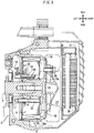
- FIG. 3 is a sectional view of the ACG starter motor 8.
- the crankshaft 2 of the engine E is supported by bearings 4 and 5 fitted in a crankcase 3.
- a connecting rod 7 is connected to the crankshaft 2 through a crankpin 6, and a driving side pulley 11 of a V-belt type continuously variable transmission is provided on the outer side in the widthwise direction of the bearing 5.
- the driving side pulley 11 includes a fixed pulley piece 11a and a movable pulley piece 11b, and the fixed pulley piece 11 a is fixed to a rather near end portion of the crankshaft 2.
- the movable pulley piece 11b is coupled against rotation in a circumferential direction but for sliding movement in an axial direction with respect to the crankshaft 2.
- the movable pulley piece 11b is engaged for sliding movement by a ramp plate 12 that is coupled for integral rotation to the crankshaft 2.
- the ramp plate 12 is disposed in an opposing relationship to an inner side inclination of the movable pulley piece 11b such that it forms a tapering guide for a roller weight 13, whose width decreases in a direction toward the outer circumference.
- a driven side pulley 20 is paired with the driving side pulley 11 to configure the continuously variable transmission.
- a driven shaft 22 is supported for rotation by a bearing 21 fitted in a transmission case 14, and the driven side pulley 20 is attached to the driven shaft 22.
- the driven side pulley 20 includes a fixed pulley piece 20a supported for rotation but against sliding movement in an axial direction of the driven shaft 22 with respect to the driven shaft 22 by bearings 23 and 24, and a movable pulley piece 20b supported against rotation in a circumferential direction but for sliding movement in an axial direction with respect to the driven shaft 22.
- a shoe supporting plate 27 which supports a clutch shoe 25 that is displaced in a direction toward the outer circumference by centrifugal force.
- a clutch outer 28 is fixed which has an inner circumferential face with which the clutch shoe 25 is to abut, and the centrifugal clutch C is configured from the combination of the clutch outer 28 and the clutch shoe 25.
- the movable pulley piece 20b is pressed by one end of a coil spring 33 that is held at the other end thereof by the shoe supporting plate 27 such that the movable pulley piece 20b is normally biased to the fixed pulley piece 20a side.
- a V belt 29 extends between the driving side pulley 11 and the driven side pulley 20.
- the driven shaft 22 is connected to the rear wheel WR through a speed reducer including a reduction gear 26.
- a cover 30 that supports a kick starter 31 covers the outer side of the transmission case 14 in the vehicle widthwise direction.
- the ACG starter motor 8 includes a stator 9 on which three-phase windings are wound, and an outer rotor 10 coupled to an end portion of the crankshaft 2 such that it rotates along an outer circumference of the stator 9.
- the outer rotor 10 includes a cup-shaped rotor case 10a connected to the crankshaft 2 and a magnet 10b accommodated in an inner circumferential face of the rotor case 10a.
- the outer rotor 10 is fixed by a bolt 42 that is attached such that the inner circumference of a hub portion 10c is fitted with a distal end tapering portion of the crankshaft 2 and extends through the center of the hub portion 10c until it is fitted with an end portion thread of the crankshaft 2.
- the stator 9 disposed on the inner circumference side of the outer rotor 10 is fixed to the crankcase 3 by a bolt 32.
- a fan 37 is fixed to the outer rotor 10 by a bolt 39.
- a radiator 38 is provided adjacent the fan 37 and is covered with a fan cover 41.
- a sensor case 34 is fitted on the inner circumference of the stator 9, and rotor angle sensors 40 and ignition pulsers 16 are provided at equal distances along an outer circumference of a boss of the outer rotor 10 in the sensor case 34.
- the rotor angle sensors 40 are used for energization control of a stator coil 35 of the ACG starter motor 8 and are provided one by one in a corresponding relationship to the U phase, V phase and W phase of the ACG starter motor 8.
- the rotor angle sensors 40 and the ignition pulsers 16 can each be configured from a Hall integrated circuit (IC) or a magneto-resistive element. It is to be noted that each rotor angle sensor 40 may be used as an engine speed sensor.
- Leads of the rotor angle sensors 40 and the ignition pulsers 16 are connected to a board 17, and a wire harness 18 is coupled to the board 17.
- a magnet ring 19 is fitted on an outer circumference of the boss 10c of the outer rotor 10 and is magnetized to two stages so as to have a magnetic action to both of the rotor angle sensors 40 and the ignition pulsers 16.
- N poles and S poles are formed such that they are arrayed alternatively at distances of a 30-degree width in a circumferential direction corresponding to the magnetic poles of the stator 9, and on the other magnetized zone of the magnet ring 19 corresponding to the ignition pulsers 16, a magnetized region is formed over a range of 15 degrees to 40 degrees at one place in the circumferential direction.
- the ACG starter motor 8 functions as synchronous motor upon starting and is driven by current supplied from a battery to rotate the crankshaft 2 to start the engine E, but functions, after starting, as a synchronous generator such that it charges the battery with generated current and supplies current to the associated electric components.
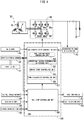
- FIG. 4 is a block diagram depicting a configuration of an electronic control unit (ECU) 100 that controls the ACG starter motor 8 and peripheral equipment.
- a full wave rectifier 36 includes field effect transistors (FETs) 36a, 36b, 36c, 36d, 36e and 36f connected to the U, V and W phases of the stator coil 35 of the ACG starter motor 8.
- the ECU 100 as a control unit includes an ACG starter motor controlling unit 57 and an idle stop controlling unit 58. To the ACG starter motor controlling unit 57, a generated voltage detected by a generated voltage detection unit 43, an engine speed Ne detected by the Ne sensor 45 and an opening TH of the throttle grip as a throttle operator 47 detected by the throttle opening sensor 50 are inputted.
- the ACG starter motor controlling unit 57 includes an acceleration assist controlling unit 53, a centrifugal clutch disconnection Ne storage unit 54, an engine start controlling unit 55 and a power generation controlling unit 56.
- the acceleration assist controlling unit 53 executes, when a predetermined condition is satisfied, acceleration assist control for increasing the rising rate of the engine speed Ne by the rotational driving force of the ACG starter motor 8.
- the centrifugal clutch disconnection Ne storage unit 54 is a memory for storing a designed engine speed Ne at which the mechanical centrifugal clutch C is disconnected.
- the engine start controlling unit 55 performs switching control of the FETs 36a to 36f upon starting of the engine E such that the ACG starter motor 8 is driven as a synchronous generator.
- the power generation controlling unit 56 rectifies AC generated power of the ACG starter motor 8 with the FETs 36a to 36f to switch the FETs 36a to 36f with the power generation controlling unit 56 such that, during power generation by engine driving, retard angle energization or advance angle energization to the stator coil 35 may be performed to increase or decrease the power generation amount.
- retard angle energization and the advance angle energization signify that the stator coil 35 is energized retarding or advancing the electrical angle by an amount corresponding to a scheduled electrical angle from a detection signal upon change in magnetic pole of the magnetized zone of the magnet ring 19 detected by the rotor angle sensors 40.
- the IS mode changeover switch 48 is a switch that allows the passenger to arbitrarily select whether or not idle stop control is to be executed and is disposed on the steering handlebar 60 or the like.
- the idle stop controlling unit 58 executes idle stop control for controlling an ignition system 51 and a fuel injection system 52 to temporarily stop the engine E and restarting the engine E in response to an opening operation of the throttle operator 47.
- the engine control device is configured such that, upon deceleration of the vehicle, fuel injection is stopped until the engine speed Ne becomes equal to or lower than a centrifugal clutch disconnection Ne to reduce the fuel consumption amount.
- the engine control device is characterized in that the ACG starter motor 8 is drive to assist rise of the engine speed Ne to reduce the period of time required until the centrifugal clutch C is connected thereby to improve the acceleration response.
- FIG. 5 is a time chart depicting a flow when the motorcycle 1 enters an idle stop state with deceleration of the motorcycle 1.
- the throttle opening TH, vehicle speed V, engine speed Ne, on/off state of fuel injection, on/off state (connection/disconnection state) of the centrifugal clutch C, power generation load F and on/off state of motor assist are indicated.
- the motorcycle 1 is traveling with a throttle opening TH1 and at a vehicle speed Va and an engine speed Ne4.
- the fuel injection is in an on state
- the centrifugal clutch is in an on state
- the generation load is F1
- the motor assist is in an off state.
- the throttle opening TH is reduced to zero by the driver.
- the fuel injection is set so as to be changed over to an off state (injection stop) in response to that the throttle opening TH becomes zero.
- injection stop In response to the injection stop, the vehicle speed V, engine speed Ne and power generation load F begin to decrease.
- the power generation load F is changed over to zero in response to that the engine speed Ne decreases to a power generation stop speed NeA (for example, 2500 rpm).
- a power generation stop speed NeA for example, 2500 rpm.
- the engine speed Ne becomes equal to or lower than a centrifugal clutch disconnection speed Ne3 (for example, 2200 rpm) and the centrifugal clutch C is changed over to a disconnection state (clutch out).
- the power generation stop speed NeA is set to a speed higher than the centrifugal clutch disconnection speed Ne3. Consequently, upon deceleration of the vehicle, the feeling of braking by the power generation load F is removed first, and then the feeling of braking by the centrifugal clutch C is removed. Consequently, since the feeling of braking is removed stepwise, the feeling of idle running that is likely to occur when the centrifugal clutch C is disconnected can be suppressed.
- the engine speed Ne becomes equal to or lower than an injection restart speed Ne2 (for example, 1800 rpm) and fuel injection is restarted.
- This injection restart is executed in order to prevent the engine speed Ne from decreasing excessively and smoothly transit to idle operation.
- idle operation at an idle speed Ne1 (for example, 1400 rpm) is started.
- the motorcycle 1 still remains decelerating and the vehicle speed V is not zero as yet.
- the vehicle speed V becomes equal to or lower than a predetermined value (for example, 3 km/h), and counting of an idle stop inrush timer is started.
- the vehicle speed V becomes zero, and at time t8, the count value started at time t6 reaches a predetermined time period (for example, 0.5 seconds) T1, whereupon the fuel injection is turned off and the engine E enters a temporary stopping state.
- stop of the ignition system 51 may be executed together. Further, by setting the idle speed Ne1 (for example, 1400 rpm) to a speed higher than an operating speed (for example, 1200 rpm) of a mechanical decompression device that operates by centrifugal force, changeover noise between operation and nonoperation of the decompression device can be prevented from being generated during idle operation.
- Ne1 for example, 1400 rpm
- an operating speed for example, 1200 rpm
- FIG. 6 is a time chart depicting a flow in the case where a throttle operation is performed after the centrifugal clutch C is disconnected with deceleration of the motorcycle 1.
- the motorcycle 1 is travelling with the throttle opening TH1 and at the vehicle speed Va and the engine speed Ne4.
- the fuel injection is in an on state;
- the centrifugal clutch is in an on state;
- the energization load is F1; and
- the motor assist is in an off state.
- the throttle opening TH is reduced to zero by the driver in order to decelerate the vehicle.
- fuel injection is set so as to be changed over to an off state (injection stop) in response to that the throttle opening TH decreases to zero.
- the engine speed Ne becomes equal to or lower than the centrifugal clutch disconnection speed Ne3, and the centrifugal clutch C is changed over to a disconnection state. Then, in this "pattern 1," the throttle opening TH is opened rapidly to a predetermined opening TH1 at time t12.
- the engine control device is configured such that, in the case where the throttle operator 47 is operated for opening after the engine speed Ne becomes equal to or lower than the centrifugal clutch disconnection speed Ne3, normal fuel injection is started and acceleration assist by the ACG starter motor 8 is executed to quickly raise the engine speed Ne.
- the acceleration assist by the ACG starter motor 8 continues to be executed till time t14.
- the period of time for which acceleration assist is performed can be set so as to increase as the amount ⁇ TH of change of the throttle opening TH increases.
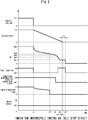
- FIG. 7 is a time chart depicting a flow in the case where a throttle operation is performed after the centrifugal clutch C is disconnected with deceleration of the motorcycle 1.
- the motorcycle 1 is travelling with the throttle opening TH1 and at the vehicle speed Va and the engine speed Ne4.
- the fuel injection is in an on state; the centrifugal clutch is in an on state; and the motor assist is in an off state.
- the throttle opening TH is reduced to zero by the driver, and the fuel injection is changed over to an off state.
- the engine speed Ne becomes equal to or lower than the centrifugal clutch disconnection speed Ne3, and the centrifugal clutch C is changed over to a disconnection state.
- the engine speed Ne becomes equal to or lower than the injection restart speed Ne2, and fuel injection is restarted in order to smoothly transit to idle operation.
- the ECU 100 starts normal fuel injection and executes acceleration assist by the ACG starter motor 8 to quickly increase the engine speed Ne.
- normal fuel injection of the fuel injection system 52 is started by the idle stop controlling unit 58, and acceleration assist driving of the ACG starter motor 8 is started by the acceleration assist controlling unit 53. Consequently, the engine speed Ne increases quickly in comparison with Nen (indicated by a one-dot chain line in FIG. 7 ) in the case where there is no acceleration assist.
- the centrifugal clutch C is connected at time t24, and the timing at which the vehicle speed V starts its increase becomes earlier in comparison with Vn (indicated by a one-dot chain line in FIG. 7 ) in the case where there is no acceleration assist, and the acceleration response is improved.
- FIG. 8 is a time chart depicting a flow in the case where a throttle operation is performed after the centrifugal clutch C is disconnected with deceleration of the motorcycle 1.
- the motorcycle 1 is travelling with the throttle opening TH1 and at the vehicle speed Va and the engine speed Ne4.
- the fuel injection is in an on state; the centrifugal clutch is in an on state; and the motor assist is in an off state.
- the throttle opening TH is reduced to zero by the driver, and the fuel injection is changed over to an off state.
- the engine speed Ne becomes equal to or lower than the centrifugal clutch disconnection speed Ne3, and the centrifugal clutch C is changed over to a disconnection state.
- the engine speed Ne becomes equal to or lower than the injection restart speed Ne2, and fuel injection is restarted in order to smoothly transit to idle operation.
- idle operation is started with the idle speed Ne1.
- the throttle opening TH is opened rapidly to the predetermined opening TH1.
- the ECU 100 starts normal fuel injection and executes acceleration assist by the ACG starter motor 8 to quickly increase the engine speed Ne.
- normal fuel information of the fuel injection system 52 is started by the idle stop controlling unit 58, and acceleration assist driving of the ACG starter motor 8 is started by the acceleration assist controlling unit 53.
- the engine speed Ne increases quickly in comparison with Nen (indicated by a one-dot chain line in FIG. 8 ) in the case where there is no acceleration assist.
- the centrifugal clutch C is connected at time t35 and the timing at which the vehicle speed V starts increase becomes earlier in comparison with Vn (indicated by a one-dot chain line in FIG. 8 ) in the case where there is no acceleration assist, and the acceleration response is improved.
- FIG. 9 is a time chart depicting a flow when the motorcycle 1 enters an idle stop state through motor idle control by the ACG starter motor 8 with deceleration of the motorcycle 1.
- the motorcycle 1 is travelling with the throttle opening TH1 and at the vehicle speed Va and the engine speed Ne4.
- the fuel injection is in an on state; the centrifugal clutch is in an on state; and the motor assist is in an off state.
- the throttle opening TH is reduced to zero by the driver in order to decelerate the vehicle.
- the fuel injection is changed over to an off state in response to that the throttle opening TH decreases to zero.
- the vehicle speed V and the engine speed Ne start decrease in response to the injection stop.
- the engine speed Ne becomes equal to or lower than the centrifugal clutch disconnection speed Ne3, and the centrifugal clutch C is changed over to a disconnection state.
- the present embodiment is configured such that, in order to further reduce the fuel consumption amount, motor idle control for performing idle operation with driving force of the ACG starter motor 8 is executed. Therefore, at time t42, idle assist for transiting to motor idle control smoothly is started in place of restarting of injection.
- FIG. 10 is a time chart depicting a flow in the case where a throttle operation is performed during motor idling by the ACG starter motor 8 with deceleration of the motorcycle 1.
- the motorcycle 1 is travelling with the throttle opening TH1 and at the vehicle speed Va and the engine speed Ne4.
- the fuel injection is in an on state; the centrifugal clutch is in an on state; and the motor assist is in an off state.
- the throttle opening TH is decreased to zero by the driver, and the fuel injection is changed over to an off state.
- the engine speed Ne becomes equal to or lower than the centrifugal clutch disconnection speed Ne3, and the centrifugal clutch C is changed over to a disconnection state.
- the engine speed Ne becomes equal to or lower than the injection restart speed Ne2, and idle assist is started in order to smoothly transit to motor idle operation.
- motor idle operation with the idle speed Ne1 is started.
- the throttle opening TH is rapidly opened to the predetermined opening TH1.
- the ECU 100 starts normal fuel injection and executes acceleration assist for increasing the speed of rotation of the ACG starter motor 8 to quickly increase the engine speed Ne.
- the engine speed Ne increases quickly and the centrifugal clutch C is connected at time t55, and the acceleration response is improved.
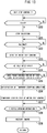
- FIG. 11 is a flow chart depicting a procedure of idle stop control according to the present embodiment. This flow chart corresponds to the flow of the time chart depicted in FIG. 5 till engine temporary stop by idle stop.
- step S3 it is decided whether or not the engine speed Ne is equal to or lower than the injection restart speed Ne2. If an affirmative decision is made at step S3, then the processing advances to step S4, at which idle operation by restart of injection is started.
- step S5 it is decided whether or not the vehicle speed V is equal to or lower than a predetermined value V1 (for example, 3 km/h) for vehicle stop decision, and if an affirmative decision is made, then the processing advances to step S6.
- a predetermined period T1 of time for example, 0.5 seconds
- step S7 an idle stop condition is satisfied, for example, by that the throttle opening TH is zero and the seating sensor 49 is in an on state in addition to the condition of the vehicle speed V.
- step S8 the engine E is temporarily stopped by the stop of fuel injection.
- step S9 it is decided whether or not a throttle opening operation is performed during the temporary stop of the engine E. If an affirmative decision is made at step S9, then the processing advances to step S10, at which the ACG starter motor 8 is driven to restart the engine E, thereby, ending the series of control. It is to be noted that, if a negative decision is made at step S1, S3, S5, S6 or S9, the processing returns to the respective decision.
- FIG. 12 is a flow chart depicting a procedure of acceleration assist control according to the present embodiment. This flow chart corresponds to the flows of the time charts of FIGS. 6 , 7 and 8 .
- step S13 it is decided whether or not the engine speed Ne is equal to or lower than the centrifugal clutch disconnection speed Ne3. If an affirmative decision is made at step S13, then the processing advances to step S14, at which the centrifugal clutch C is disconnected.
- step S15 it is decided whether or not the throttle operator 47 is operated for opening, and if an affirmative decision is made, then the processing advances to step S16.
- step S16 acceleration assist control by the ACG starter motor 8 is executed, and then, at step S17, normal injection is started, whereafter the processing advances to step S28.
- step S15 the processing advances to step S18, at which it is decided whether or not the engine speed Ne is equal to or lower than the injection restart speed Ne2. If an affirmative decision is made at step S18, then the processing advances to step S19, at which fuel injection is restarted. Then, at step S20, it is decided whether or not the throttle operator 47 is operated for opening, and if an affirmative decision is made, then the processing advances to step S21.
- step S21 acceleration assist control by the ACG starter motor 8 is executed, and then, at step S22, normal injection is started, whereafter the processing advances to step S28. It is to be noted that, if a negative decision is made at step S18, then the processing returns to the decision at step S15.
- step S20 the processing advances to step S23, at which it is decided whether or not the engine speed Ne is equal to or lower than the idle speed Ne1. If an affirmative decision is made at step S23, then the processing advances to step S24, at which idle operation is started. Then, at step S25, it is decided whether or not the throttle operator 47 is operated for opening, and if an affirmative decision is made, then the processing advances to step S26.
- step S26 acceleration assist control by the ACG starter motor 8 is executed, and then, at step S27, normal injection is started, whereafter the processing advances to step S28. It is to be noted that, if a negative decision is made at step S25, then the processing returns to step S24.
- step S28 the engine speed Ne increases with the start of the acceleration assist control by the ACG starter motor 8 and normal fuel injection. Consequently, at step S29, the centrifugal clutch C is changed over to a connection state, and at step S30, the vehicle starts acceleration, thereby ending the series of control.
- acceleration assist control when a throttle operation is performed after the engine speed Ne becomes equal to or lower than the centrifugal clutch disconnection speed Ne3 at which the centrifugal clutch C is disconnected, acceleration assist control by the ACG starter motor 8 is executed. Therefore, it is possible to reduce the time lag before the centrifugal clutch C is connected and improve the acceleration response. It is to be noted that, in the case where a throttle operation is performed in an engine stop state by idle stop control, cranking by the ACG starter motor 8 and normal fuel injection are started simultaneously.
- FIG. 13 is a flow chart depicting a procedure of idle stop control 2 according to the present embodiment. This flow chart corresponds to the flow of the time chart of FIG. 9 till engine temporary stop by idle stop.
- step S32 it is decided whether or not the engine speed Ne is equal to or lower than the injection restart speed Ne2. If an affirmative decision is made at step S32, then the processing advances to step S33, at which motor idle operation by the ACG starter motor 8 is started.
- step S34 it is decided whether or not the vehicle speed V is equal to or lower than the predetermined value V1 (for example, 3 km/h) for vehicle stop decision, and if an affirmative decision is made, then the processing advances to step S35.
- step S35 it is decided whether or not the predetermined period T1 of time (for example 0.5 seconds) elapses after the vehicle speed V becomes equal to or lower than the predetermined value V1. If an affirmative decision is made at step S35, then the processing advances to step S36.
- step S36 an idle stop condition is satisfied by that, for example, the throttle opening TH is zero and the seating sensor 49 is an on state in addition to the satisfaction of the condition of the vehicle speed V.
- step S37 the engine E is temporarily stopped by the stop of the motor idle control.
- step S38 it is decided whether or not a throttle opening operation is performed during temporary stopping of the engine E. If an affirmative decision is made at step S38, then the processing advances to step S39, at which the ACG starter motor 8 is driven to restart the engine E, thereby ending the series of control. It is to be noted that, if a negative decision is made at step S30, S32, S34, S35 or S38, then the processing returns to the respective decision.
- the idle assist control may be configured such that, in addition to idle operation only with the driving force of the ACG starter motor 8, idle operation is executed by cooperation of motor driving force and engine driving force to reduce the fuel consumption amount.
- FIG. 14 is a flow chart depicting a procedure of idle stop control 3 according to the present embodiment.
- the predetermined period T1 of time for example, 0.5 seconds
- V1 for example, 3 km/h
- step S40 an idle stop condition other than the vehicle speed, for example, that the throttle opening TH is 0 and the seating sensor 49 is in an on state or the like, is satisfied, and the processing advances to step S41.
- step S41 it is decided whether or not the vehicle speed V is equal to or lower than the predetermined value V1.
- step S41 If an affirmative decision is made at step S41, then the processing advances to step S42, at which it is decided whether or not there is a history that the vehicle speed exceeds a predetermined value V2 (for example, 13 km/h) after the idle stop control in the preceding cycle. Then, if an affirmative decision is made at step S42, then the processing advances to step S43, at which the engine E is temporarily stopped after lapse of the predetermined period T1 of time (for example, 0.5 seconds). On the other hand, if a negative decision is made at step S42, then the processing advances to step S44, at which the engine E is temporarily stopped after lapse of a second predetermined period T2 of time (for example, 3 seconds), thereby ending the series of control.
- a predetermined value V2 for example, 13 km/h
- the setting described above is also a setting that reduces the burden on the battery upon traveling in a traffic jam and makes improvement of the comprehensive energy efficiency. It is to be noted that the values of the predetermined periods T1 and T2 of time and the predetermined values V1 and V2 of the vehicle speed can be changed suitably in accordance with a vehicle model or the like.
- the form of the motorcycle, the structure and the operating speed of the centrifugal clutch, the structure and the form of the transmission, the structure and the form of the ACG starter motor, the execution conditions for idle stop control, execution conditions for acceleration assist control and idle assist control and so forth are not limited to those of the embodiment described hereinabove and can be altered in various manners.
- the engine control device for a vehicle according to the present invention can be applied not only to a motorcycle but also to a three-wheeled saddle riding vehicle, a four-wheeled vehicle and so forth that include a centrifugal clutch.
Landscapes
- Engineering & Computer Science (AREA)
- Mechanical Engineering (AREA)
- Chemical & Material Sciences (AREA)
- Combustion & Propulsion (AREA)
- Transportation (AREA)
- General Engineering & Computer Science (AREA)
- Automation & Control Theory (AREA)
- Human Computer Interaction (AREA)
- Control Of Vehicle Engines Or Engines For Specific Uses (AREA)
- Combined Controls Of Internal Combustion Engines (AREA)
- Hybrid Electric Vehicles (AREA)
- Electrical Control Of Air Or Fuel Supplied To Internal-Combustion Engine (AREA)
- One-Way And Automatic Clutches, And Combinations Of Different Clutches (AREA)
Abstract
Description
- The present invention relates to an engine control device for a vehicle, and particularly to an engine control device for a vehicle applied to a vehicle in which a centrifugal clutch is used for connection and disconnection of engine driving force.
- Conventionally, a configuration is known by which, in order to improve the fuel cost of a vehicle that uses an engine as a power source, in the case where there is no acceleration request, fuel injection is stopped even during rotation of the engine. In the case where such stopping control of fuel injection like this is performed, a scheme is required for suppressing a driver from having a disagreeable feeling when fuel injection is restarted.
-
Patent Literature 1 discloses an engine control device for a vehicle including a torque converter and a lockup clutch, which is configured such that, after fuel injection is stopped due to absence of an acceleration request, if the engine speed becomes lower than a predetermined value in a state in which the lockup clutch is connected, then fuel injection is restarted such that a lean combustion state is established, and after fuel injection is restarted, the lockup clutch is disconnected. According to this configuration, while torque variation is suppressed, engine stall can be prevented by lean combustion. - Patent Document 1:
JP 2001-98978 A - Incidentally, different from such an electronically controlled clutch as disclosed in
Patent Literature 1, in a mechanical centrifugal clutch with which the connection/disconnection state of engine driving force changes over at a predetermined speed, the connection state cannot be changed over arbitrarily. In a vehicle in which such a centrifugal clutch like this is applied to a start clutch, it can be considered that, in the case where fuel injection is stopped upon deceleration in order to improve the fuel cost, also after the centrifugal clutches changes over to a disconnection state, the stopping state of fuel injection is continued until just before the engine stops. However, in the case where an acceleration request is issued during disconnection of the centrifugal clutch, even if fuel injection is restarted, some period of time is required before the engine speed increases until the centrifugal clutch is connected. This gives rise to a subject that some delay is liable to occur in acceleration response. - The object of the present invention resides in provision of an engine control device for a saddle riding (saddled) vehicle that can solve the subject of the prior art described above and can improve the acceleration response from a state in which the engine speed is lower than an engine speed at which a centrifugal clutch is disconnected.
- To achieve the afore-mentioned object, the present invention has a first feature in that an engine control device for a vehicle applied to a vehicle (1) includes a mechanical centrifugal clutch (C) for connecting and disconnecting driving force to be transmitted from an engine (E) to a driving wheel (WR), wherein the vehicle (1) includes a throttle operator (47) configured to adjust output power of the engine (E), a motor (8) configured to rotate a crankshaft (2) of the engine (E), and a control unit (100) configured to control the motor (8) and a fuel injection system (52), and the control unit (100) executes injection stopping control for stopping fuel injection during deceleration of the vehicle (1) and executes, when an opening operation of the throttle operator (47) is performed after an engine speed (Ne) becomes equal to or lower than a centrifugal clutch disconnection speed (Ne3) at which the centrifugal clutch (C) is disconnected, acceleration assist control for rotating the crankshaft (2) with the motor (8).
- To achieve the afore-mentioned object, the present invention has a second feature in that when the engine speed (Ne) decreases to an injection restart speed (Ne2) that is lower than the centrifugal clutch disconnection speed (Ne3) after fuel injection by the injection stopping control stops, the control unit (100) causes the fuel injection to be restarted.
- To achieve the afore-mentioned object, the present invention has a third feature in that the injection restart speed (Ne2) at which the fuel injection is to be restarted is higher than an idle speed (Ne1).
- To achieve the afore-mentioned object, the present invention has a fourth feature in that when the engine (E) is caused to operate with an idle speed (Ne1), the control unit (100) executes idle assist control for causing the motor (8) to rotate the crankshaft (2).
- To achieve the afore-mentioned object, the present invention has a fifth feature in that an engine control device for a vehicle applied to a vehicle (1) includes a mechanical centrifugal clutch (C) for connecting and disconnecting driving force to be transmitted from an engine (E) to a driving wheel (WR), wherein the vehicle (1) includes a throttle operator (47) configured to adjust output power of the engine (E), a motor (8) configured to rotate a crankshaft (2) of the engine (E), and a control unit (100) configured to control the motor (8) and a fuel injection system (52), the control unit (100) causes fuel injection to be stopped during deceleration of the vehicle (1) and executes, when an opening operation of the throttle operator (47) is performed after an engine speed (Ne) becomes equal to or lower than a centrifugal clutch disconnection speed (Ne3) at which the centrifugal clutch (C) is disconnected, acceleration assist control for causing the motor (8) to rotate the crankshaft (2), the control unit (100) executes, when the engine (E) is to be caused to operate with an idle speed (Ne1), idle assist control for causing the motor (8) to rotate the crankshaft (2), and the idle assist control is control for causing the engine (E) to operate with the idle speed (Ne1) only by driving force of the motor (8).
- According to the first feature of the present invention, an engine control device for a vehicle applied to a vehicle (1) includes a mechanical centrifugal clutch (C) for connecting and disconnecting driving force to be transmitted from an engine (E) to a driving wheel (WR), wherein the vehicle (1) includes a throttle operator (47) configured to adjust output power of the engine (E), a motor (8) configured to rotate a crankshaft (2) of the engine (E), and a control unit (100) configured to control the motor (8) and a fuel injection system (52), and the control unit (100) executes injection stopping control for stopping fuel injection during deceleration of the vehicle (1) and executes, when an opening operation of the throttle operator (47) is performed after an engine speed (Ne) becomes equal to or lower than a centrifugal clutch disconnection speed (Ne3) at which the centrifugal clutch (C) is disconnected, acceleration assist control for rotating the crankshaft (2) with the motor (8). Therefore, since fuel injection is stopped during deceleration of the vehicle, the fuel consumption can be suppressed and an acceleration delay in the case where the throttle is operated for opening in a state in which the centrifugal clutch is disconnected can be reduced.
- Particularly, even if the throttle is operated for opening in a state in which the centrifugal clutch is disconnected, the vehicle is accelerated actually only after the centrifugal clutch is connected after the engine speed starts increase, and therefore, a delay is likely to occur in acceleration response to the opening operation of the throttle. However, since the crankshaft is accelerated by the motor in response to an opening operation of the throttle, the time required until the centrifugal clutch is connected can be reduced to improve the acceleration response.
- According to the second feature of the present invention, when the engine speed (Ne) decreases to an injection restart speed (Ne2) that is lower than the centrifugal clutch disconnection speed (Ne3) after fuel injection by the injection stopping control stops, the control unit (100) causes the fuel injection to be restarted. Therefore, the fuel consumption amount can be suppressed by elongating the stop period of fuel injection. Further, although it is necessary to restart injection in order to transit to idle operation after fuel injection is stopped upon deceleration, by executing the restart of fuel injection after the centrifugal clutch is disconnected, it is possible to transit to idle operation without having an influence on the driving force to be transmitted to the driving wheel.
- According to the third feature of the present invention, the injection restart speed (Ne2) at which the fuel injection is to be restarted is higher than an idle speed (Ne1). Therefore, even in the case where some ignition delay or the like occurs upon restart of injection, it is possible to transit to idle operation smoothly without causing such a situation that the engine speed becomes lower than the idle speed or engine stall occurs.
- According to the fourth feature of the present invention, when the engine (E) is caused to operate with an idle speed (Ne1), the control unit (100) executes idle assist control for causing the motor (8) to rotate the crankshaft (2). Therefore, for example, by performing idle operation using both of fuel injection and idle assist control, it is possible to reduce the fuel consumption amount upon idle operation.
- According to the fifth feature of the present invention, an engine control device for a vehicle applied to a vehicle (1) includes a mechanical centrifugal clutch (C) for connecting and disconnecting driving force to be transmitted from an engine (E) to a driving wheel (WR), wherein the vehicle (1) includes a throttle operator (47) configured to adjust output power of the engine (E), a motor (8) configured to rotate a crankshaft (2) of the engine (E), and a control unit (100) configured to control the motor (8) and a fuel injection system (52), the control unit (100) causes fuel injection to be stopped during deceleration of the vehicle (1) and executes, when an opening operation of the throttle operator (47) is performed after an engine speed (Ne) becomes equal to or lower than a centrifugal clutch disconnection speed (Ne3) at which the centrifugal clutch (C) is disconnected, acceleration assist control for causing the motor (8) to rotate the crankshaft (2), the control unit (100) executes, when the engine (E) is to be caused to operate with an idle speed (Ne1), idle assist control for causing the motor (8) to rotate the crankshaft (2), and the idle assist control is control for causing the engine (E) to operate with the idle speed (Ne1) only by driving force of the motor (8). Therefore, by stopping fuel injection during deceleration of the vehicle, the fuel consumption can be suppressed, and an acceleration delay in the case where the throttle is operated for opening in a state in which the centrifugal clutch is disconnected can be reduced. Further, since idle operation is performed only with the motor driving force, after fuel injection is stopped once upon deceleration, there is no necessity to inject the fuel before restart of the vehicle, and the fuel consumption amount can be reduced further.
-
- [
FIG. 1] FIG. 1 is a left side elevational view of a motorcycle to which an engine control device for a vehicle according to an embodiment of the present invention is applied. - [
FIG. 2] FIG. 2 is a sectional view of the swing unit. - [
FIG. 3] FIG. 3 is a sectional view of the ACG starter motor. - [
FIG. 4] FIG. 4 is a block diagram depicting a configuration of an ECU that controls the ACG starter motor and peripheral equipment. - [
FIG. 5] FIG. 5 is a time chart depicting a flow when the motorcycle enters an idle stop state with deceleration of the motorcycle. - [
FIG. 6] FIG. 6 is a time chart (pattern 2) depicting a flow in the case where a throttle operation is performed after the centrifugal clutch is disconnected with deceleration of the motorcycle. - [
FIG. 7] FIG. 7 is a time chart (pattern 2) depicting a flow in the case where a throttle operation is performed after the centrifugal clutch is disconnected with deceleration of the motorcycle. - [
FIG. 8] FIG. 8 is a time chart (pattern 3) depicting a flow in the case where a throttle operation is performed after the centrifugal clutch is disconnected with deceleration of the motorcycle. - [
FIG. 9] FIG. 9 is a time chart depicting a flow when the motorcycle enters an idle stop state through idle assist by the ACG starter motor with deceleration of the motorcycle. - [
FIG. 10] FIG. 10 is a time chart depicting a flow in the case where a throttle operation is performed during motor idling by the ACG starter motor with deceleration of the motorcycle. - [
FIG. 11] FIG. 11 is a flow chart depicting a procedure of idle stop control according to the present embodiment. - [
FIG. 12] FIG. 12 is a flow chart depicting a procedure of acceleration assist control according to the present embodiment. - [
FIG. 13] FIG. 13 is a flow chart depicting a procedure ofidle stop control 2 according to the present embodiment. - [
FIG. 14] FIG. 14 is a flow chart depicting a procedure ofidle stop control 3 according to the present embodiment. - In the following, a preferred embodiment of the present invention is described in detail with reference to the drawings.
FIG. 1 is a left side elevational view of amotorcycle 1 to which an engine control device for a vehicle according to an embodiment of the present invention is applied. Themotorcycle 1 is a saddle riding (saddled) vehicle of the scooter type that includes a front wheel WF supported for steering movement by asteering handlebar 60, a rear wheel WR supported at a rear portion of aswing unit 70 that configures an engine E and a transmission integrally, and aseat 62 provided between the front wheel WF and the rear wheel WR such that a passenger is seated astride theseat 62. To acrankshaft 2 of the engine E, an alternating-current generating (ACG)starter motor 8 is attached which rotates thecrankshaft 2 when power is supplied thereto and functions, after the engine E is started, as a generator. Further, themotorcycle 1 has an idle stop function of stopping the engine E if a predetermined stopping condition is satisfied and restarting the engine E if a predetermined restarting condition is satisfied. - The
motorcycle 1 includes avehicle body frame 63, and alink mechanism 65 extends rearwardly of the vehicle from thevehicle body frame 63 through alink pivot 64 as a shaft member. Theswing unit 70 is supported for rocking motion with respect to thevehicle body frame 63 by thelink mechanism 65. Thesteering handlebar 60 is fixed to an upper end portion of asteering stem 69, and a pair of left and rightfront forks 71 for supporting the front wheel WF for rotation thereon is fixed to a lower end portion of thesteering stem 69. - The
swing unit 70 has an elongated shape in which a cylinder axial line of the engine E is inclined by a great amount toward the front side of the vehicle body and a transmission case of the transmission is disposed on the vehicle body rear side of thecrankshaft 2. On the vehicle body rear side of the transmission case, a mechanical centrifugal clutch C is disposed. An engine speed (Ne)sensor 45 is disposed in the proximity of theACG starter motor 8, and avehicle speed sensor 46 is disposed in the proximity of the axle of the rear wheel WR. - The
vehicle body frame 63 includes ahead pipe 85 at a front end portion of which thesteering stem 69 is supported for rotation, adown frame 86 extending rearwardly downwards of the vehicle from thehead pipe 85, a pair of left and rightlower frames 87 extending rearwardly of the vehicle from a lower portion of thedown frame 86, and a seat frame 88 extending rearwardly upwards of the vehicle from a rear end portion of thelower frames 87 and supporting theseat 62 thereon. Between a rear portion of theswing unit 70 that has a function also of a swing arm and the seat frame 88, acushion unit 66 is interposed. An aircleaner box 68 is provided on an upper face of theswing unit 70. - A
cross frame 91 bridges the pair of left and rightlower frames 87 such that it is directed in a vehicle widthwise direction, and afront cross frame 92 bridges between the pair of left and rightlower frames 87 on the front side of the vehicle with respect to thecross frame 91 such that it is directed in the vehicle widthwise direction while a lower end of thedown frame 86 is connected to a front face of thefront cross frame 92. - On the outer side of the
vehicle body frame 63, afront cover 73 that covers a front portion of the vehicle body, afloor panel 74 attached so as to cover the steering stem 69 from the rear of thefront cover 73, a pair of left and right side covers 75 extending rearwardly of the vehicle body from an end portion of thefront cover 73, atunnel member 76 that bridges the left and right side covers 75 in front of theseat 62, a pair of left and right under covers 78 on each of which astep floor 77 on which the driver is to place its feet is formed, and left and right rear side covers 79 extending rearwardly of the vehicle body from a lower portion of theseat 62 are disposed. Awindshield 80 is attached to an upper end of thefront cover 73. Afront fender 81 is disposed above the front wheel WF, and arear fender 83 is disposed rearwardly upwardly of the rear wheel WR. - On the right side of the steering
handlebar 60, athrottle opening sensor 50 for detecting the opening of a throttle grip for being operated by the driver is disposed, and aseating sensor 49 for detecting a seated state of the driver is disposed in the inside of theseat 62. -
FIG. 2 is a sectional view of theswing unit 70.FIG. 3 is a sectional view of theACG starter motor 8. Thecrankshaft 2 of the engine E is supported bybearings crankcase 3. A connectingrod 7 is connected to thecrankshaft 2 through acrankpin 6, and a drivingside pulley 11 of a V-belt type continuously variable transmission is provided on the outer side in the widthwise direction of thebearing 5. The drivingside pulley 11 includes a fixedpulley piece 11a and amovable pulley piece 11b, and the fixedpulley piece 11 a is fixed to a rather near end portion of thecrankshaft 2. - The
movable pulley piece 11b is coupled against rotation in a circumferential direction but for sliding movement in an axial direction with respect to thecrankshaft 2. Themovable pulley piece 11b is engaged for sliding movement by aramp plate 12 that is coupled for integral rotation to thecrankshaft 2. Theramp plate 12 is disposed in an opposing relationship to an inner side inclination of themovable pulley piece 11b such that it forms a tapering guide for aroller weight 13, whose width decreases in a direction toward the outer circumference. - A driven
side pulley 20 is paired with the drivingside pulley 11 to configure the continuously variable transmission. A drivenshaft 22 is supported for rotation by a bearing 21 fitted in atransmission case 14, and the drivenside pulley 20 is attached to the drivenshaft 22. The drivenside pulley 20 includes a fixedpulley piece 20a supported for rotation but against sliding movement in an axial direction of the drivenshaft 22 with respect to the drivenshaft 22 bybearings movable pulley piece 20b supported against rotation in a circumferential direction but for sliding movement in an axial direction with respect to the drivenshaft 22. - On the fixed
pulley piece 20a, ashoe supporting plate 27 is provided which supports aclutch shoe 25 that is displaced in a direction toward the outer circumference by centrifugal force. To the drivenshaft 22, a clutch outer 28 is fixed which has an inner circumferential face with which theclutch shoe 25 is to abut, and the centrifugal clutch C is configured from the combination of the clutch outer 28 and theclutch shoe 25. Themovable pulley piece 20b is pressed by one end of acoil spring 33 that is held at the other end thereof by theshoe supporting plate 27 such that themovable pulley piece 20b is normally biased to the fixedpulley piece 20a side. -
A V belt 29 extends between the drivingside pulley 11 and the drivenside pulley 20. The drivenshaft 22 is connected to the rear wheel WR through a speed reducer including areduction gear 26. Acover 30 that supports akick starter 31 covers the outer side of thetransmission case 14 in the vehicle widthwise direction. - Referring to
FIG. 3 , theACG starter motor 8 includes astator 9 on which three-phase windings are wound, and anouter rotor 10 coupled to an end portion of thecrankshaft 2 such that it rotates along an outer circumference of thestator 9. Theouter rotor 10 includes a cup-shapedrotor case 10a connected to thecrankshaft 2 and amagnet 10b accommodated in an inner circumferential face of therotor case 10a. - The
outer rotor 10 is fixed by abolt 42 that is attached such that the inner circumference of ahub portion 10c is fitted with a distal end tapering portion of thecrankshaft 2 and extends through the center of thehub portion 10c until it is fitted with an end portion thread of thecrankshaft 2. Thestator 9 disposed on the inner circumference side of theouter rotor 10 is fixed to thecrankcase 3 by abolt 32. Afan 37 is fixed to theouter rotor 10 by abolt 39. Aradiator 38 is provided adjacent thefan 37 and is covered with afan cover 41. - A
sensor case 34 is fitted on the inner circumference of thestator 9, androtor angle sensors 40 andignition pulsers 16 are provided at equal distances along an outer circumference of a boss of theouter rotor 10 in thesensor case 34. Therotor angle sensors 40 are used for energization control of astator coil 35 of theACG starter motor 8 and are provided one by one in a corresponding relationship to the U phase, V phase and W phase of theACG starter motor 8. Therotor angle sensors 40 and theignition pulsers 16 can each be configured from a Hall integrated circuit (IC) or a magneto-resistive element. It is to be noted that eachrotor angle sensor 40 may be used as an engine speed sensor. - Leads of the
rotor angle sensors 40 and theignition pulsers 16 are connected to aboard 17, and awire harness 18 is coupled to theboard 17. Amagnet ring 19 is fitted on an outer circumference of theboss 10c of theouter rotor 10 and is magnetized to two stages so as to have a magnetic action to both of therotor angle sensors 40 and theignition pulsers 16. On one of the magnetized zones of themagnet ring 19 corresponding to therotor angle sensors 40, N poles and S poles are formed such that they are arrayed alternatively at distances of a 30-degree width in a circumferential direction corresponding to the magnetic poles of thestator 9, and on the other magnetized zone of themagnet ring 19 corresponding to theignition pulsers 16, a magnetized region is formed over a range of 15 degrees to 40 degrees at one place in the circumferential direction. - The
ACG starter motor 8 functions as synchronous motor upon starting and is driven by current supplied from a battery to rotate thecrankshaft 2 to start the engine E, but functions, after starting, as a synchronous generator such that it charges the battery with generated current and supplies current to the associated electric components. -
FIG. 4 is a block diagram depicting a configuration of an electronic control unit (ECU) 100 that controls theACG starter motor 8 and peripheral equipment. Afull wave rectifier 36 includes field effect transistors (FETs) 36a, 36b, 36c, 36d, 36e and 36f connected to the U, V and W phases of thestator coil 35 of theACG starter motor 8. TheECU 100 as a control unit includes an ACG startermotor controlling unit 57 and an idlestop controlling unit 58. To the ACG startermotor controlling unit 57, a generated voltage detected by a generatedvoltage detection unit 43, an engine speed Ne detected by theNe sensor 45 and an opening TH of the throttle grip as athrottle operator 47 detected by thethrottle opening sensor 50 are inputted. - The ACG starter
motor controlling unit 57 includes an accelerationassist controlling unit 53, a centrifugal clutch disconnectionNe storage unit 54, an enginestart controlling unit 55 and a powergeneration controlling unit 56. The accelerationassist controlling unit 53 executes, when a predetermined condition is satisfied, acceleration assist control for increasing the rising rate of the engine speed Ne by the rotational driving force of theACG starter motor 8. The centrifugal clutch disconnectionNe storage unit 54 is a memory for storing a designed engine speed Ne at which the mechanical centrifugal clutch C is disconnected. Further, the engine start controllingunit 55 performs switching control of the FETs 36a to 36f upon starting of the engine E such that theACG starter motor 8 is driven as a synchronous generator. After the engine E is started, the powergeneration controlling unit 56 rectifies AC generated power of theACG starter motor 8 with the FETs 36a to 36f to switch theFETs 36a to 36f with the powergeneration controlling unit 56 such that, during power generation by engine driving, retard angle energization or advance angle energization to thestator coil 35 may be performed to increase or decrease the power generation amount. It is to be noted that the retard angle energization and the advance angle energization signify that thestator coil 35 is energized retarding or advancing the electrical angle by an amount corresponding to a scheduled electrical angle from a detection signal upon change in magnetic pole of the magnetized zone of themagnet ring 19 detected by therotor angle sensors 40. - On the other hand, to the idle
stop controlling unit 58, output signals of thethrottle opening sensor 50, thevehicle speed sensor 46, theseating sensor 49 and an idle stop (IS)mode changeover switch 48 are inputted. The ISmode changeover switch 48 is a switch that allows the passenger to arbitrarily select whether or not idle stop control is to be executed and is disposed on the steeringhandlebar 60 or the like. Using the conditions, for example, that the ISmode changeover switch 48 is on, that the throttle opening TH is zero, that a predetermined period of time elapses after themotorcycle 1 comes to a stopping state and that the driver is seated on theseat 62, the idlestop controlling unit 58 executes idle stop control for controlling anignition system 51 and afuel injection system 52 to temporarily stop the engine E and restarting the engine E in response to an opening operation of thethrottle operator 47. - In the following, flows of controls executed by the engine control device according to the present embodiment are described with reference to time charts of
FIGS. 5 to 10 . The engine control device is configured such that, upon deceleration of the vehicle, fuel injection is stopped until the engine speed Ne becomes equal to or lower than a centrifugal clutch disconnection Ne to reduce the fuel consumption amount. Then, although, in the case where a throttle opening operation is performed after the engine speed Ne becomes equal to or lower than the centrifugal clutch disconnection Ne, a delay in acceleration response is likely to occur from the fact that some time is required until the centrifugal clutch C is connected, the engine control device is characterized in that theACG starter motor 8 is drive to assist rise of the engine speed Ne to reduce the period of time required until the centrifugal clutch C is connected thereby to improve the acceleration response. -
FIG. 5 is a time chart depicting a flow when themotorcycle 1 enters an idle stop state with deceleration of themotorcycle 1. In this time chart, in order from above, the throttle opening TH, vehicle speed V, engine speed Ne, on/off state of fuel injection, on/off state (connection/disconnection state) of the centrifugal clutch C, power generation load F and on/off state of motor assist are indicated. - At time t = 0, the
motorcycle 1 is traveling with a throttle opening TH1 and at a vehicle speed Va and an engine speed Ne4. At this time, the fuel injection is in an on state, the centrifugal clutch is in an on state, the generation load is F1 and the motor assist is in an off state. - At time t1, in order to decelerate the vehicle, the throttle opening TH is reduced to zero by the driver. In the present embodiment, the fuel injection is set so as to be changed over to an off state (injection stop) in response to that the throttle opening TH becomes zero. In response to the injection stop, the vehicle speed V, engine speed Ne and power generation load F begin to decrease.
- At time t2, the power generation load F is changed over to zero in response to that the engine speed Ne decreases to a power generation stop speed NeA (for example, 2500 rpm). At time t3, the engine speed Ne becomes equal to or lower than a centrifugal clutch disconnection speed Ne3 (for example, 2200 rpm) and the centrifugal clutch C is changed over to a disconnection state (clutch out).
- It is to be noted that the power generation stop speed NeA is set to a speed higher than the centrifugal clutch disconnection speed Ne3. Consequently, upon deceleration of the vehicle, the feeling of braking by the power generation load F is removed first, and then the feeling of braking by the centrifugal clutch C is removed. Consequently, since the feeling of braking is removed stepwise, the feeling of idle running that is likely to occur when the centrifugal clutch C is disconnected can be suppressed.
- At time t4, the engine speed Ne becomes equal to or lower than an injection restart speed Ne2 (for example, 1800 rpm) and fuel injection is restarted. This injection restart is executed in order to prevent the engine speed Ne from decreasing excessively and smoothly transit to idle operation.
- At time t5, idle operation at an idle speed Ne1 (for example, 1400 rpm) is started. At this time, the
motorcycle 1 still remains decelerating and the vehicle speed V is not zero as yet. At time t6, the vehicle speed V becomes equal to or lower than a predetermined value (for example, 3 km/h), and counting of an idle stop inrush timer is started. At time t7, the vehicle speed V becomes zero, and at time t8, the count value started at time t6 reaches a predetermined time period (for example, 0.5 seconds) T1, whereupon the fuel injection is turned off and the engine E enters a temporary stopping state. - It is to be noted that, although, in the present embodiment, temporary stop of the engine E is executed by stop of fuel injection, stop of the
ignition system 51 may be executed together. Further, by setting the idle speed Ne1 (for example, 1400 rpm) to a speed higher than an operating speed (for example, 1200 rpm) of a mechanical decompression device that operates by centrifugal force, changeover noise between operation and nonoperation of the decompression device can be prevented from being generated during idle operation. -
FIG. 6 is a time chart depicting a flow in the case where a throttle operation is performed after the centrifugal clutch C is disconnected with deceleration of themotorcycle 1. In particular, a flow in the case of a "pattern 1" in which thethrottle operator 47 is operated for opening within a period after the engine speed Ne becomes equal to or lower than the centrifugal clutch disconnection speed Ne3 until the engine speed Ne becomes the injection restart speed Ne2. - At time t = 0, the
motorcycle 1 is travelling with the throttle opening TH1 and at the vehicle speed Va and the engine speed Ne4. At this time, the fuel injection is in an on state; the centrifugal clutch is in an on state; the energization load is F1; and the motor assist is in an off state. - At time t10, the throttle opening TH is reduced to zero by the driver in order to decelerate the vehicle. In the present embodiment, fuel injection is set so as to be changed over to an off state (injection stop) in response to that the throttle opening TH decreases to zero.
- At time t11, the engine speed Ne becomes equal to or lower than the centrifugal clutch disconnection speed Ne3, and the centrifugal clutch C is changed over to a disconnection state. Then, in this "
pattern 1," the throttle opening TH is opened rapidly to a predetermined opening TH1 at time t12. - The engine control device according to the present embodiment is configured such that, in the case where the
throttle operator 47 is operated for opening after the engine speed Ne becomes equal to or lower than the centrifugal clutch disconnection speed Ne3, normal fuel injection is started and acceleration assist by theACG starter motor 8 is executed to quickly raise the engine speed Ne. - In particular, at time t12, normal fuel injection of the
fuel injection system 52 is started by the idle stop controlling unit 58 (refer toFIG. 4 ), and acceleration assist driving of theACG starter motor 8 is started by the acceleration assist controllingunit 53. Consequently, the engine speed Ne increases quickly in comparison with Nen (indicated by a one-dot chain line inFIG. 6 ) in the case where there is no acceleration assist. As a result, the centrifugal clutch C is connected at time t13 and the timing at which the vehicle speed V starts its increase comes earlier in comparison with Vn (indicated by a one-dot chain line inFIG. 6 ) in the case where there is no acceleration assist, and the acceleration response is improved. - It is to be noted that, in the example of
FIG. 6 , also after the engine speed Ne becomes equal to or higher than the centrifugal clutch disconnection speed Ne3 at time t13, the acceleration assist by theACG starter motor 8 continues to be executed till time t14. The period of time for which acceleration assist is performed can be set so as to increase as the amount ΔTH of change of the throttle opening TH increases. -
FIG. 7 is a time chart depicting a flow in the case where a throttle operation is performed after the centrifugal clutch C is disconnected with deceleration of themotorcycle 1. In particular, a flow in the case of a "pattern 2" in which thethrottle operator 47 is operated for opening within a period after the engine speed Ne becomes equal to or lower than the injection restart speed Ne2 until it becomes the idle speed Ne1. - At time t = 0, the
motorcycle 1 is travelling with the throttle opening TH1 and at the vehicle speed Va and the engine speed Ne4. At this time, the fuel injection is in an on state; the centrifugal clutch is in an on state; and the motor assist is in an off state. - At time t20, the throttle opening TH is reduced to zero by the driver, and the fuel injection is changed over to an off state. At time t21, the engine speed Ne becomes equal to or lower than the centrifugal clutch disconnection speed Ne3, and the centrifugal clutch C is changed over to a disconnection state. Then, at time t22, the engine speed Ne becomes equal to or lower than the injection restart speed Ne2, and fuel injection is restarted in order to smoothly transit to idle operation.
- Then, in this "
pattern 2," after fuel injection is restarted at time t22, the throttle opening TH is opened rapidly to the predetermined opening TH1 at time t23 before the engine speed Ne decreases to the idle speed Ne1. - In response to the rapid opening, the
ECU 100 starts normal fuel injection and executes acceleration assist by theACG starter motor 8 to quickly increase the engine speed Ne. In particular, at time t23, normal fuel injection of thefuel injection system 52 is started by the idlestop controlling unit 58, and acceleration assist driving of theACG starter motor 8 is started by the acceleration assist controllingunit 53. Consequently, the engine speed Ne increases quickly in comparison with Nen (indicated by a one-dot chain line inFIG. 7 ) in the case where there is no acceleration assist. As a result, the centrifugal clutch C is connected at time t24, and the timing at which the vehicle speed V starts its increase becomes earlier in comparison with Vn (indicated by a one-dot chain line inFIG. 7 ) in the case where there is no acceleration assist, and the acceleration response is improved. -
FIG. 8 is a time chart depicting a flow in the case where a throttle operation is performed after the centrifugal clutch C is disconnected with deceleration of themotorcycle 1. In particular, a flow in the case of a "pattern 3" in which thethrottle operator 47 is operated for opening during idle operation at the idle speed Ne1. - At time t = 0, the
motorcycle 1 is travelling with the throttle opening TH1 and at the vehicle speed Va and the engine speed Ne4. At this time, the fuel injection is in an on state; the centrifugal clutch is in an on state; and the motor assist is in an off state. - At time t30, the throttle opening TH is reduced to zero by the driver, and the fuel injection is changed over to an off state. At time t31, the engine speed Ne becomes equal to or lower than the centrifugal clutch disconnection speed Ne3, and the centrifugal clutch C is changed over to a disconnection state. Then, at time t32, the engine speed Ne becomes equal to or lower than the injection restart speed Ne2, and fuel injection is restarted in order to smoothly transit to idle operation. Then, at time t33, idle operation is started with the idle speed Ne1.
- In this "
pattern 3," at time t34 during idle operation, the throttle opening TH is opened rapidly to the predetermined opening TH1. In response to the rapid opening, theECU 100 starts normal fuel injection and executes acceleration assist by theACG starter motor 8 to quickly increase the engine speed Ne. In particular, at time t34, normal fuel information of thefuel injection system 52 is started by the idlestop controlling unit 58, and acceleration assist driving of theACG starter motor 8 is started by the acceleration assist controllingunit 53. As a result, the engine speed Ne increases quickly in comparison with Nen (indicated by a one-dot chain line inFIG. 8 ) in the case where there is no acceleration assist. Consequently, the centrifugal clutch C is connected at time t35 and the timing at which the vehicle speed V starts increase becomes earlier in comparison with Vn (indicated by a one-dot chain line inFIG. 8 ) in the case where there is no acceleration assist, and the acceleration response is improved. -
FIG. 9 is a time chart depicting a flow when themotorcycle 1 enters an idle stop state through motor idle control by theACG starter motor 8 with deceleration of themotorcycle 1. At time t = 0, themotorcycle 1 is travelling with the throttle opening TH1 and at the vehicle speed Va and the engine speed Ne4. At this time, the fuel injection is in an on state; the centrifugal clutch is in an on state; and the motor assist is in an off state. - At time t40, the throttle opening TH is reduced to zero by the driver in order to decelerate the vehicle. In the present embodiment, the fuel injection is changed over to an off state in response to that the throttle opening TH decreases to zero. The vehicle speed V and the engine speed Ne start decrease in response to the injection stop. At time t41, the engine speed Ne becomes equal to or lower than the centrifugal clutch disconnection speed Ne3, and the centrifugal clutch C is changed over to a disconnection state.
- At time t42, the engine speed Ne becomes equal to or lower than the injection restart speed Ne2. Here, the present embodiment is configured such that, in order to further reduce the fuel consumption amount, motor idle control for performing idle operation with driving force of the
ACG starter motor 8 is executed. Therefore, at time t42, idle assist for transiting to motor idle control smoothly is started in place of restarting of injection. - At time t43, motor idle operation with the idle speed Ne1 is started. At this time, the
motorcycle 1 is still in deceleration and the vehicle speed V does not become zero as yet. At time t44, the vehicle speed V becomes equal to or lower than a predetermined value (for example, 3 km/h), and thereupon, the idle stop inrush timer starts counting. At time t45, the vehicle speed V becomes zero, and at time t46, the count value started at time t44 reaches a predetermined time period (for example, 0.5 seconds) T1, and thereupon, the idle assist is turned off and the engine E enters a temporarily stopping state. -
FIG. 10 is a time chart depicting a flow in the case where a throttle operation is performed during motor idling by theACG starter motor 8 with deceleration of themotorcycle 1. At time t = 0, themotorcycle 1 is travelling with the throttle opening TH1 and at the vehicle speed Va and the engine speed Ne4. At this time, the fuel injection is in an on state; the centrifugal clutch is in an on state; and the motor assist is in an off state. - At time t50, the throttle opening TH is decreased to zero by the driver, and the fuel injection is changed over to an off state. At time t51, the engine speed Ne becomes equal to or lower than the centrifugal clutch disconnection speed Ne3, and the centrifugal clutch C is changed over to a disconnection state. Then, at time t52, the engine speed Ne becomes equal to or lower than the injection restart speed Ne2, and idle assist is started in order to smoothly transit to motor idle operation. Then, at time t53, motor idle operation with the idle speed Ne1 is started.
- In this time chart, at time t54 during motor idle operation, the throttle opening TH is rapidly opened to the predetermined opening TH1. In response to the rapid opening, the
ECU 100 starts normal fuel injection and executes acceleration assist for increasing the speed of rotation of theACG starter motor 8 to quickly increase the engine speed Ne. As a result, the engine speed Ne increases quickly and the centrifugal clutch C is connected at time t55, and the acceleration response is improved. -
FIG. 11 is a flow chart depicting a procedure of idle stop control according to the present embodiment. This flow chart corresponds to the flow of the time chart depicted inFIG. 5 till engine temporary stop by idle stop. At step S1, it is decided whether or not the throttle opening TH is TH = 0 (zero). If an affirmative decision is made at step S1, then the processing advances to step S2, at which fuel injection is stopped. It is to be noted that also it is possible to execute this stop of fuel injection upon deceleration using that the deceleration of the vehicle speed detected by thevehicle speed sensor 46 exceeds a predetermined value or the like as a trigger. - At step S3, it is decided whether or not the engine speed Ne is equal to or lower than the injection restart speed Ne2. If an affirmative decision is made at step S3, then the processing advances to step S4, at which idle operation by restart of injection is started.
- Then, at step S5, it is decided whether or not the vehicle speed V is equal to or lower than a predetermined value V1 (for example, 3 km/h) for vehicle stop decision, and if an affirmative decision is made, then the processing advances to step S6. At step S6, it is decided whether or not a predetermined period T1 of time (for example, 0.5 seconds) elapses after the vehicle speed V becomes equal to or lower than the predetermined value V1. If an affirmative decision is made at step S6, then the processing advances to step S7.
- At step S7, an idle stop condition is satisfied, for example, by that the throttle opening TH is zero and the
seating sensor 49 is in an on state in addition to the condition of the vehicle speed V. Together with this, at step S8, the engine E is temporarily stopped by the stop of fuel injection. At step S9, it is decided whether or not a throttle opening operation is performed during the temporary stop of the engine E. If an affirmative decision is made at step S9, then the processing advances to step S10, at which theACG starter motor 8 is driven to restart the engine E, thereby, ending the series of control. It is to be noted that, if a negative decision is made at step S1, S3, S5, S6 or S9, the processing returns to the respective decision. -
FIG. 12 is a flow chart depicting a procedure of acceleration assist control according to the present embodiment. This flow chart corresponds to the flows of the time charts ofFIGS. 6 ,7 and8 . At step S11, it is decided whether or not the throttle opening TH is TH = 0 (zero). If an affirmative decision is made at step S11, then the processing advances to step S12, at which fuel injection is stopped. - At step S13, it is decided whether or not the engine speed Ne is equal to or lower than the centrifugal clutch disconnection speed Ne3. If an affirmative decision is made at step S13, then the processing advances to step S14, at which the centrifugal clutch C is disconnected.
- At step S15, it is decided whether or not the
throttle operator 47 is operated for opening, and if an affirmative decision is made, then the processing advances to step S16. At step S16, acceleration assist control by theACG starter motor 8 is executed, and then, at step S17, normal injection is started, whereafter the processing advances to step S28. - On the other hand, if a negative decision is made at step S15, then the processing advances to step S18, at which it is decided whether or not the engine speed Ne is equal to or lower than the injection restart speed Ne2. If an affirmative decision is made at step S18, then the processing advances to step S19, at which fuel injection is restarted. Then, at step S20, it is decided whether or not the
throttle operator 47 is operated for opening, and if an affirmative decision is made, then the processing advances to step S21. At step S21, acceleration assist control by theACG starter motor 8 is executed, and then, at step S22, normal injection is started, whereafter the processing advances to step S28. It is to be noted that, if a negative decision is made at step S18, then the processing returns to the decision at step S15. - Furthermore, if a negative decision is made at step S20, then the processing advances to step S23, at which it is decided whether or not the engine speed Ne is equal to or lower than the idle speed Ne1. If an affirmative decision is made at step S23, then the processing advances to step S24, at which idle operation is started. Then, at step S25, it is decided whether or not the
throttle operator 47 is operated for opening, and if an affirmative decision is made, then the processing advances to step S26. At step S26, acceleration assist control by theACG starter motor 8 is executed, and then, at step S27, normal injection is started, whereafter the processing advances to step S28. It is to be noted that, if a negative decision is made at step S25, then the processing returns to step S24. - At step S28, the engine speed Ne increases with the start of the acceleration assist control by the
ACG starter motor 8 and normal fuel injection. Consequently, at step S29, the centrifugal clutch C is changed over to a connection state, and at step S30, the vehicle starts acceleration, thereby ending the series of control. - As described above, with the acceleration assist control according to the present embodiment, when a throttle operation is performed after the engine speed Ne becomes equal to or lower than the centrifugal clutch disconnection speed Ne3 at which the centrifugal clutch C is disconnected, acceleration assist control by the
ACG starter motor 8 is executed. Therefore, it is possible to reduce the time lag before the centrifugal clutch C is connected and improve the acceleration response. It is to be noted that, in the case where a throttle operation is performed in an engine stop state by idle stop control, cranking by theACG starter motor 8 and normal fuel injection are started simultaneously. -
FIG. 13 is a flow chart depicting a procedure ofidle stop control 2 according to the present embodiment. This flow chart corresponds to the flow of the time chart ofFIG. 9 till engine temporary stop by idle stop. At step S30, it is decided whether or not the throttle opening TH is TH = 0 (zero). If an affirmative decision is made at step S30, then the processing advances to step S31, at which fuel injection is stopped. - At step S32, it is decided whether or not the engine speed Ne is equal to or lower than the injection restart speed Ne2. If an affirmative decision is made at step S32, then the processing advances to step S33, at which motor idle operation by the
ACG starter motor 8 is started. - At step S34, it is decided whether or not the vehicle speed V is equal to or lower than the predetermined value V1 (for example, 3 km/h) for vehicle stop decision, and if an affirmative decision is made, then the processing advances to step S35. At step S35, it is decided whether or not the predetermined period T1 of time (for example 0.5 seconds) elapses after the vehicle speed V becomes equal to or lower than the predetermined value V1. If an affirmative decision is made at step S35, then the processing advances to step S36.
- At step S36, an idle stop condition is satisfied by that, for example, the throttle opening TH is zero and the
seating sensor 49 is an on state in addition to the satisfaction of the condition of the vehicle speed V. With this, at step S37, the engine E is temporarily stopped by the stop of the motor idle control. At step S38, it is decided whether or not a throttle opening operation is performed during temporary stopping of the engine E. If an affirmative decision is made at step S38, then the processing advances to step S39, at which theACG starter motor 8 is driven to restart the engine E, thereby ending the series of control. It is to be noted that, if a negative decision is made at step S30, S32, S34, S35 or S38, then the processing returns to the respective decision. - With the motor idle control described above, it is possible to reduce the fuel consumption amount during idle operation to zero by causing the engine to perform idle operation with the driving force of the
ACG starter motor 8. It is to be noted that the idle assist control may be configured such that, in addition to idle operation only with the driving force of theACG starter motor 8, idle operation is executed by cooperation of motor driving force and engine driving force to reduce the fuel consumption amount. -
FIG. 14 is a flow chart depicting a procedure ofidle stop control 3 according to the present embodiment. Although it is possible to include, in the conditions for temporarily stopping the engine E by idle stop control, the condition that the predetermined period T1 of time (for example, 0.5 seconds) elapses after the vehicle speed V becomes equal to or lower than the predetermined value V1 (for example, 3 km/h) as described hereinabove, if the predetermined period of time is changed over in response to a travel history, then it is possible to make the idle stop control more comfortable. - At step S40, an idle stop condition other than the vehicle speed, for example, that the throttle opening TH is 0 and the
seating sensor 49 is in an on state or the like, is satisfied, and the processing advances to step S41. At step S41, it is decided whether or not the vehicle speed V is equal to or lower than the predetermined value V1. - If an affirmative decision is made at step S41, then the processing advances to step S42, at which it is decided whether or not there is a history that the vehicle speed exceeds a predetermined value V2 (for example, 13 km/h) after the idle stop control in the preceding cycle. Then, if an affirmative decision is made at step S42, then the processing advances to step S43, at which the engine E is temporarily stopped after lapse of the predetermined period T1 of time (for example, 0.5 seconds). On the other hand, if a negative decision is made at step S42, then the processing advances to step S44, at which the engine E is temporarily stopped after lapse of a second predetermined period T2 of time (for example, 3 seconds), thereby ending the series of control.
- According to this control, while, in the case of signal waiting after normal travel in which the speed is raised to a speed equal to or higher than a certain level, the engine stops in a short period of time, in the case of travel in a traffic jam in which travel at a low speed and stop are repeated or in a like case, the period of time until the engine stops is elongated. According to this setting, there is an advantageous effect that, although, in a vehicle that includes the centrifugal clutch C, a time lag occurs until the centrifugal clutch C is connected upon restarting from an idle stop state, it is possible to prevent stopping and restarting of the engine upon traveling in a traffic jam from being repeated and cause a response delay to be prevented from being felt. Further, if stopping and restarting of the engine are repeated, then also the fuel improvement effect decreases, and therefore, the setting described above is also a setting that reduces the burden on the battery upon traveling in a traffic jam and makes improvement of the comprehensive energy efficiency. It is to be noted that the values of the predetermined periods T1 and T2 of time and the predetermined values V1 and V2 of the vehicle speed can be changed suitably in accordance with a vehicle model or the like.
- It is to be noted that the form of the motorcycle, the structure and the operating speed of the centrifugal clutch, the structure and the form of the transmission, the structure and the form of the ACG starter motor, the execution conditions for idle stop control, execution conditions for acceleration assist control and idle assist control and so forth are not limited to those of the embodiment described hereinabove and can be altered in various manners. The engine control device for a vehicle according to the present invention can be applied not only to a motorcycle but also to a three-wheeled saddle riding vehicle, a four-wheeled vehicle and so forth that include a centrifugal clutch.
- 1 ... Motorcycle (vehicle), 2 ... Crankshaft, 8 ... ACG starter motor (motor), 45 ... Ne sensor, 47 ... Throttle grip (throttle operator), 50 ... Throttle opening sensor, 53 ... Acceleration assist controlling unit, 54 ... Centrifugal clutch disconnection Ne storage unit, 55 ... Engine start controlling unit, 56 ... Power generation controlling unit, 57 ... ACG starter motor controlling unit, 58 ... Idle stop controlling unit, 100 ... ECU (control unit), C ... Centrifugal clutch, E ... Engine, Ne1 ... Idle speed, Ne2 ... Injection restart speed, Ne3 ... Centrifugal clutch disconnection speed
Claims (5)
- An engine control device for a vehicle applied to a vehicle (1) that includes a mechanical centrifugal clutch (C) for connecting and disconnecting driving force to be transmitted from an engine (E) to a driving wheel (WR), wherein
the vehicle (1) includes a throttle operator (47) configured to adjust output power of the engine (E), a motor (8) configured to rotate a crankshaft (2) of the engine (E), and a control unit (100) configured to control the motor (8) and a fuel injection system (52), and
the control unit (100) executes injection stopping control for stopping fuel injection during deceleration of the vehicle (1) and executes, when an opening operation of the throttle operator (47) is performed after an engine speed (Ne) becomes equal to or lower than a centrifugal clutch disconnection speed (Ne3) at which the centrifugal clutch (C) is disconnected, acceleration assist control for rotating the crankshaft (2) with the motor (8). - The engine control device for a vehicle according to claim 1, wherein
when the engine speed (Ne) decreases to an injection restart speed (Ne2) that is lower than the centrifugal clutch disconnection speed (Ne3) after fuel injection by the injection stopping control stops, the control unit (100) causes the fuel injection to be restarted. - The engine control device for a vehicle according to claim 2, wherein
the injection restart speed (Ne2) at which the fuel injection is to be restarted is higher than an idle speed (Ne1). - The engine control device for a vehicle according to any one of claims 1 to 3, wherein
when the engine (E) is caused to operate with an idle speed (Ne1), the control unit (100) executes idle assist control for causing the motor (8) to rotate the crankshaft (2). - An engine control device for a vehicle applied to a vehicle (1) that includes a mechanical centrifugal clutch (C) for connecting and disconnecting driving force to be transmitted from an engine (E) to a driving wheel (WR), wherein
the vehicle (1) includes a throttle operator (47) configured to adjust output power of the engine (E), a motor (8) configured to rotate a crankshaft (2) of the engine (E), and a control unit (100) configured to control the motor (8) and a fuel injection system (52),
the control unit (100) causes fuel injection to be stopped during deceleration of the vehicle (1) and executes, when an opening operation of the throttle operator (47) is performed after an engine speed (Ne) becomes equal to or lower than a centrifugal clutch disconnection speed (Ne3) at which the centrifugal clutch (C) is disconnected, acceleration assist control for causing the motor (8) to rotate the crankshaft (2),
the control unit (100) executes, when the engine (E) is to be caused to operate with an idle speed (Ne1), idle assist control for causing the motor (8) to rotate the crankshaft (2), and
the idle assist control is control for causing the engine (E) to operate with the idle speed (Ne1) only by driving force of the motor (8).
Applications Claiming Priority (2)
| Application Number | Priority Date | Filing Date | Title |
|---|---|---|---|
| JP2017057267 | 2017-03-23 | ||
| PCT/JP2018/010649 WO2018173982A1 (en) | 2017-03-23 | 2018-03-16 | Engine control device for vehicle |
Publications (3)
| Publication Number | Publication Date |
|---|---|
| EP3604775A1 true EP3604775A1 (en) | 2020-02-05 |
| EP3604775A4 EP3604775A4 (en) | 2020-04-22 |
| EP3604775B1 EP3604775B1 (en) | 2021-10-20 |
Family
ID=63585400
Family Applications (1)
| Application Number | Title | Priority Date | Filing Date |
|---|---|---|---|
| EP18770904.3A Active EP3604775B1 (en) | 2017-03-23 | 2018-03-16 | Engine control device for vehicle |
Country Status (8)
| Country | Link |
|---|---|
| US (1) | US11358587B2 (en) |
| EP (1) | EP3604775B1 (en) |
| JP (1) | JP6823159B2 (en) |
| CN (1) | CN110462184B (en) |
| BR (1) | BR112019018931A2 (en) |
| MY (1) | MY194392A (en) |
| PH (1) | PH12019502006B1 (en) |
| WO (1) | WO2018173982A1 (en) |
Families Citing this family (3)
| Publication number | Priority date | Publication date | Assignee | Title |
|---|---|---|---|---|
| JP2022149908A (en) * | 2021-03-25 | 2022-10-07 | 本田技研工業株式会社 | vehicle controller |
| US12084043B2 (en) * | 2022-04-14 | 2024-09-10 | Ford Global Technologies, Llc | System and method for restarting an engine |
| JP2025093221A (en) * | 2023-12-11 | 2025-06-23 | カワサキモータース株式会社 | Control circuit and vehicle |
Family Cites Families (18)
| Publication number | Priority date | Publication date | Assignee | Title |
|---|---|---|---|---|
| JPH03148332A (en) * | 1989-11-01 | 1991-06-25 | Mitsubishi Motors Corp | Hybrid engine |
| JPH10339187A (en) * | 1997-06-04 | 1998-12-22 | Suzuki Motor Corp | Engine fuel cut control device |
| JP4267144B2 (en) | 1999-09-30 | 2009-05-27 | 三菱自動車工業株式会社 | Vehicle control device |
| JP4008437B2 (en) | 2004-08-10 | 2007-11-14 | 本田技研工業株式会社 | Power module drive control device and hybrid vehicle |
| JP4281740B2 (en) * | 2005-12-27 | 2009-06-17 | トヨタ自動車株式会社 | Vehicle and control method thereof |
| JP4755039B2 (en) * | 2006-07-25 | 2011-08-24 | ヤマハ発動機株式会社 | Hybrid motorcycle |
| FR2908476B1 (en) * | 2006-11-13 | 2009-03-20 | Mitsubishi Electric Corp | CONTROL DEVICE FOR INTERNAL COMBUSTION ENGINE |
| EP1953367B1 (en) * | 2007-01-31 | 2019-08-14 | Yamaha Hatsudoki Kabushiki Kaisha | Vehicle engine idle speed control |
| JP4811505B2 (en) * | 2009-07-29 | 2011-11-09 | マツダ株式会社 | ENGINE CONTROL METHOD AND CONTROL DEVICE |
| JP5236044B2 (en) * | 2011-05-11 | 2013-07-17 | 三菱電機株式会社 | Automatic stop / restart device for internal combustion engine |
| CN104350260B (en) * | 2012-06-14 | 2017-05-17 | 三菱电机株式会社 | Engine starting device and engine starting method |
| US9511761B2 (en) | 2012-10-19 | 2016-12-06 | Kubota Corporation | Hybrid vehicle |
| JP6000135B2 (en) * | 2013-01-10 | 2016-09-28 | 株式会社クボタ | Hybrid vehicle |
| WO2014112173A1 (en) * | 2013-01-18 | 2014-07-24 | ヤマハ発動機株式会社 | Saddle-type vehicle |
| JP2017031807A (en) * | 2013-12-20 | 2017-02-09 | ヤマハ発動機株式会社 | Engine unit and vehicle |
| JP6250484B2 (en) * | 2014-06-20 | 2017-12-20 | 日立オートモティブシステムズ株式会社 | Automatic stop / restart control system for internal combustion engine and variable valve operating device |
| JP6431374B2 (en) * | 2015-01-06 | 2018-11-28 | 本田技研工業株式会社 | Engine automatic stop / start control device |
| US11052748B2 (en) * | 2016-07-22 | 2021-07-06 | Shindengen Electric Manufacturing Co., Ltd. | Controlling apparatus and controlling method of hybrid vehicle |
-
2018
- 2018-03-16 BR BR112019018931A patent/BR112019018931A2/en not_active IP Right Cessation
- 2018-03-16 PH PH1/2019/502006A patent/PH12019502006B1/en unknown
- 2018-03-16 WO PCT/JP2018/010649 patent/WO2018173982A1/en not_active Ceased
- 2018-03-16 MY MYPI2019005368A patent/MY194392A/en unknown
- 2018-03-16 US US16/496,208 patent/US11358587B2/en active Active
- 2018-03-16 EP EP18770904.3A patent/EP3604775B1/en active Active
- 2018-03-16 JP JP2019507649A patent/JP6823159B2/en active Active
- 2018-03-16 CN CN201880019700.1A patent/CN110462184B/en active Active
Also Published As
| Publication number | Publication date |
|---|---|
| US11358587B2 (en) | 2022-06-14 |
| MY194392A (en) | 2022-11-30 |
| JP6823159B2 (en) | 2021-01-27 |
| JPWO2018173982A1 (en) | 2020-01-16 |
| CN110462184A (en) | 2019-11-15 |
| BR112019018931A2 (en) | 2020-04-22 |
| US20200047744A1 (en) | 2020-02-13 |
| PH12019502006B1 (en) | 2024-01-31 |
| EP3604775B1 (en) | 2021-10-20 |
| WO2018173982A1 (en) | 2018-09-27 |
| PH12019502006A1 (en) | 2020-06-08 |
| EP3604775A4 (en) | 2020-04-22 |
| CN110462184B (en) | 2022-07-05 |
Similar Documents
| Publication | Publication Date | Title |
|---|---|---|
| JP3969641B2 (en) | Engine starter | |
| CN112805465B (en) | engine restart device | |
| EP3604775B1 (en) | Engine control device for vehicle | |
| JP6715389B2 (en) | Engine start control device | |
| JP6216672B2 (en) | Three-phase AC power generation starter device | |
| JP2002332938A (en) | Engine starter | |
| JP3998119B2 (en) | Engine start control device | |
| EP3054131B1 (en) | Idle stop control device | |
| JP6207327B2 (en) | Hybrid system | |
| EP3147496B1 (en) | Engine start control system for saddle-ride type vehicles | |
| JP6715387B2 (en) | Vehicle motor controller | |
| US20150167617A1 (en) | Engine starting apparatus | |
| JP4027706B2 (en) | Engine control device | |
| CN103326647B (en) | The power generation control of idling stop vehicle | |
| JP2013092096A (en) | Control device for motorcycle | |
| EP3589834B1 (en) | A starter system for a vehicle | |
| JP2010239748A (en) | Three-phase motor controller | |
| JP6434707B2 (en) | Three-phase AC power generation starter device | |
| JP2009248614A (en) | Control device of electric power steering system | |
| JP6216671B2 (en) | Three-phase AC power generation starter device | |
| CN111133188B (en) | Vehicle control device | |
| JP2019100247A (en) | Engine starter and engine starting method of engine starter |
Legal Events
| Date | Code | Title | Description |
|---|---|---|---|
| STAA | Information on the status of an ep patent application or granted ep patent |
Free format text: STATUS: THE INTERNATIONAL PUBLICATION HAS BEEN MADE |
|
| PUAI | Public reference made under article 153(3) epc to a published international application that has entered the european phase |
Free format text: ORIGINAL CODE: 0009012 |
|
| STAA | Information on the status of an ep patent application or granted ep patent |
Free format text: STATUS: REQUEST FOR EXAMINATION WAS MADE |
|
| 17P | Request for examination filed |
Effective date: 20190918 |
|
| AK | Designated contracting states |
Kind code of ref document: A1 Designated state(s): AL AT BE BG CH CY CZ DE DK EE ES FI FR GB GR HR HU IE IS IT LI LT LU LV MC MK MT NL NO PL PT RO RS SE SI SK SM TR |
|
| AX | Request for extension of the european patent |
Extension state: BA ME |
|
| RIC1 | Information provided on ipc code assigned before grant |
Ipc: F02N 11/04 20060101ALI20200311BHEP Ipc: B60K 6/485 20071001ALI20200311BHEP Ipc: B62M 6/15 20100101ALI20200311BHEP Ipc: H02P 9/00 20060101ALI20200311BHEP Ipc: F02D 41/08 20060101ALI20200311BHEP Ipc: B62J 99/00 20200101ALI20200311BHEP Ipc: B60K 6/20 20071001ALI20200311BHEP Ipc: B60W 10/08 20060101ALI20200311BHEP Ipc: F02D 45/00 20060101ALI20200311BHEP Ipc: F02D 29/00 20060101AFI20200311BHEP Ipc: F02D 41/12 20060101ALI20200311BHEP Ipc: F02D 41/02 20060101ALI20200311BHEP Ipc: B60W 10/06 20060101ALI20200311BHEP Ipc: B60W 20/19 20160101ALI20200311BHEP Ipc: F02D 29/02 20060101ALI20200311BHEP Ipc: F02D 41/10 20060101ALI20200311BHEP |
|
| A4 | Supplementary search report drawn up and despatched |
Effective date: 20200323 |
|
| DAV | Request for validation of the european patent (deleted) | ||
| DAX | Request for extension of the european patent (deleted) | ||
| STAA | Information on the status of an ep patent application or granted ep patent |
Free format text: STATUS: EXAMINATION IS IN PROGRESS |
|
| 17Q | First examination report despatched |
Effective date: 20201210 |
|
| GRAP | Despatch of communication of intention to grant a patent |
Free format text: ORIGINAL CODE: EPIDOSNIGR1 |
|
| STAA | Information on the status of an ep patent application or granted ep patent |
Free format text: STATUS: GRANT OF PATENT IS INTENDED |
|
| INTG | Intention to grant announced |
Effective date: 20210607 |
|
| INTG | Intention to grant announced |
Effective date: 20210607 |
|
| GRAS | Grant fee paid |
Free format text: ORIGINAL CODE: EPIDOSNIGR3 |
|
| GRAA | (expected) grant |
Free format text: ORIGINAL CODE: 0009210 |
|
| STAA | Information on the status of an ep patent application or granted ep patent |
Free format text: STATUS: THE PATENT HAS BEEN GRANTED |
|
| AK | Designated contracting states |
Kind code of ref document: B1 Designated state(s): AL AT BE BG CH CY CZ DE DK EE ES FI FR GB GR HR HU IE IS IT LI LT LU LV MC MK MT NL NO PL PT RO RS SE SI SK SM TR |
|
| REG | Reference to a national code |
Ref country code: GB Ref legal event code: FG4D |
|
| REG | Reference to a national code |
Ref country code: CH Ref legal event code: EP |
|
| REG | Reference to a national code |
Ref country code: IE Ref legal event code: FG4D |
|
| REG | Reference to a national code |
Ref country code: DE Ref legal event code: R096 Ref document number: 602018025377 Country of ref document: DE |
|
| REG | Reference to a national code |
Ref country code: AT Ref legal event code: REF Ref document number: 1440140 Country of ref document: AT Kind code of ref document: T Effective date: 20211115 |
|
| REG | Reference to a national code |
Ref country code: LT Ref legal event code: MG9D |
|
| REG | Reference to a national code |
Ref country code: NL Ref legal event code: MP Effective date: 20211020 |
|
| REG | Reference to a national code |
Ref country code: AT Ref legal event code: MK05 Ref document number: 1440140 Country of ref document: AT Kind code of ref document: T Effective date: 20211020 |
|
| PG25 | Lapsed in a contracting state [announced via postgrant information from national office to epo] |
Ref country code: RS Free format text: LAPSE BECAUSE OF FAILURE TO SUBMIT A TRANSLATION OF THE DESCRIPTION OR TO PAY THE FEE WITHIN THE PRESCRIBED TIME-LIMIT Effective date: 20211020 Ref country code: LT Free format text: LAPSE BECAUSE OF FAILURE TO SUBMIT A TRANSLATION OF THE DESCRIPTION OR TO PAY THE FEE WITHIN THE PRESCRIBED TIME-LIMIT Effective date: 20211020 Ref country code: FI Free format text: LAPSE BECAUSE OF FAILURE TO SUBMIT A TRANSLATION OF THE DESCRIPTION OR TO PAY THE FEE WITHIN THE PRESCRIBED TIME-LIMIT Effective date: 20211020 Ref country code: BG Free format text: LAPSE BECAUSE OF FAILURE TO SUBMIT A TRANSLATION OF THE DESCRIPTION OR TO PAY THE FEE WITHIN THE PRESCRIBED TIME-LIMIT Effective date: 20220120 Ref country code: AT Free format text: LAPSE BECAUSE OF FAILURE TO SUBMIT A TRANSLATION OF THE DESCRIPTION OR TO PAY THE FEE WITHIN THE PRESCRIBED TIME-LIMIT Effective date: 20211020 |
|
| PGFP | Annual fee paid to national office [announced via postgrant information from national office to epo] |
Ref country code: DE Payment date: 20220228 Year of fee payment: 5 |
|
| PG25 | Lapsed in a contracting state [announced via postgrant information from national office to epo] |
Ref country code: IS Free format text: LAPSE BECAUSE OF FAILURE TO SUBMIT A TRANSLATION OF THE DESCRIPTION OR TO PAY THE FEE WITHIN THE PRESCRIBED TIME-LIMIT Effective date: 20220220 Ref country code: SE Free format text: LAPSE BECAUSE OF FAILURE TO SUBMIT A TRANSLATION OF THE DESCRIPTION OR TO PAY THE FEE WITHIN THE PRESCRIBED TIME-LIMIT Effective date: 20211020 Ref country code: PT Free format text: LAPSE BECAUSE OF FAILURE TO SUBMIT A TRANSLATION OF THE DESCRIPTION OR TO PAY THE FEE WITHIN THE PRESCRIBED TIME-LIMIT Effective date: 20220221 Ref country code: PL Free format text: LAPSE BECAUSE OF FAILURE TO SUBMIT A TRANSLATION OF THE DESCRIPTION OR TO PAY THE FEE WITHIN THE PRESCRIBED TIME-LIMIT Effective date: 20211020 Ref country code: NO Free format text: LAPSE BECAUSE OF FAILURE TO SUBMIT A TRANSLATION OF THE DESCRIPTION OR TO PAY THE FEE WITHIN THE PRESCRIBED TIME-LIMIT Effective date: 20220120 Ref country code: NL Free format text: LAPSE BECAUSE OF FAILURE TO SUBMIT A TRANSLATION OF THE DESCRIPTION OR TO PAY THE FEE WITHIN THE PRESCRIBED TIME-LIMIT Effective date: 20211020 Ref country code: LV Free format text: LAPSE BECAUSE OF FAILURE TO SUBMIT A TRANSLATION OF THE DESCRIPTION OR TO PAY THE FEE WITHIN THE PRESCRIBED TIME-LIMIT Effective date: 20211020 Ref country code: HR Free format text: LAPSE BECAUSE OF FAILURE TO SUBMIT A TRANSLATION OF THE DESCRIPTION OR TO PAY THE FEE WITHIN THE PRESCRIBED TIME-LIMIT Effective date: 20211020 Ref country code: GR Free format text: LAPSE BECAUSE OF FAILURE TO SUBMIT A TRANSLATION OF THE DESCRIPTION OR TO PAY THE FEE WITHIN THE PRESCRIBED TIME-LIMIT Effective date: 20220121 Ref country code: ES Free format text: LAPSE BECAUSE OF FAILURE TO SUBMIT A TRANSLATION OF THE DESCRIPTION OR TO PAY THE FEE WITHIN THE PRESCRIBED TIME-LIMIT Effective date: 20211020 |
|
| REG | Reference to a national code |
Ref country code: DE Ref legal event code: R097 Ref document number: 602018025377 Country of ref document: DE |
|
| PG25 | Lapsed in a contracting state [announced via postgrant information from national office to epo] |
Ref country code: SM Free format text: LAPSE BECAUSE OF FAILURE TO SUBMIT A TRANSLATION OF THE DESCRIPTION OR TO PAY THE FEE WITHIN THE PRESCRIBED TIME-LIMIT Effective date: 20211020 Ref country code: SK Free format text: LAPSE BECAUSE OF FAILURE TO SUBMIT A TRANSLATION OF THE DESCRIPTION OR TO PAY THE FEE WITHIN THE PRESCRIBED TIME-LIMIT Effective date: 20211020 Ref country code: RO Free format text: LAPSE BECAUSE OF FAILURE TO SUBMIT A TRANSLATION OF THE DESCRIPTION OR TO PAY THE FEE WITHIN THE PRESCRIBED TIME-LIMIT Effective date: 20211020 Ref country code: EE Free format text: LAPSE BECAUSE OF FAILURE TO SUBMIT A TRANSLATION OF THE DESCRIPTION OR TO PAY THE FEE WITHIN THE PRESCRIBED TIME-LIMIT Effective date: 20211020 Ref country code: DK Free format text: LAPSE BECAUSE OF FAILURE TO SUBMIT A TRANSLATION OF THE DESCRIPTION OR TO PAY THE FEE WITHIN THE PRESCRIBED TIME-LIMIT Effective date: 20211020 Ref country code: CZ Free format text: LAPSE BECAUSE OF FAILURE TO SUBMIT A TRANSLATION OF THE DESCRIPTION OR TO PAY THE FEE WITHIN THE PRESCRIBED TIME-LIMIT Effective date: 20211020 |
|
| REG | Reference to a national code |
Ref country code: DE Ref legal event code: R084 Ref document number: 602018025377 Country of ref document: DE |
|
| PLBE | No opposition filed within time limit |
Free format text: ORIGINAL CODE: 0009261 |
|
| STAA | Information on the status of an ep patent application or granted ep patent |
Free format text: STATUS: NO OPPOSITION FILED WITHIN TIME LIMIT |
|
| 26N | No opposition filed |
Effective date: 20220721 |
|
| PG25 | Lapsed in a contracting state [announced via postgrant information from national office to epo] |
Ref country code: MC Free format text: LAPSE BECAUSE OF FAILURE TO SUBMIT A TRANSLATION OF THE DESCRIPTION OR TO PAY THE FEE WITHIN THE PRESCRIBED TIME-LIMIT Effective date: 20211020 Ref country code: AL Free format text: LAPSE BECAUSE OF FAILURE TO SUBMIT A TRANSLATION OF THE DESCRIPTION OR TO PAY THE FEE WITHIN THE PRESCRIBED TIME-LIMIT Effective date: 20211020 |
|
| REG | Reference to a national code |
Ref country code: CH Ref legal event code: PL |
|
| GBPC | Gb: european patent ceased through non-payment of renewal fee |
Effective date: 20220316 |
|
| PG25 | Lapsed in a contracting state [announced via postgrant information from national office to epo] |
Ref country code: SI Free format text: LAPSE BECAUSE OF FAILURE TO SUBMIT A TRANSLATION OF THE DESCRIPTION OR TO PAY THE FEE WITHIN THE PRESCRIBED TIME-LIMIT Effective date: 20211020 |
|
| REG | Reference to a national code |
Ref country code: BE Ref legal event code: MM Effective date: 20220331 |
|
| PG25 | Lapsed in a contracting state [announced via postgrant information from national office to epo] |
Ref country code: LU Free format text: LAPSE BECAUSE OF NON-PAYMENT OF DUE FEES Effective date: 20220316 Ref country code: LI Free format text: LAPSE BECAUSE OF NON-PAYMENT OF DUE FEES Effective date: 20220331 Ref country code: IE Free format text: LAPSE BECAUSE OF NON-PAYMENT OF DUE FEES Effective date: 20220316 Ref country code: GB Free format text: LAPSE BECAUSE OF NON-PAYMENT OF DUE FEES Effective date: 20220316 Ref country code: FR Free format text: LAPSE BECAUSE OF NON-PAYMENT OF DUE FEES Effective date: 20220331 Ref country code: CH Free format text: LAPSE BECAUSE OF NON-PAYMENT OF DUE FEES Effective date: 20220331 |
|
| PG25 | Lapsed in a contracting state [announced via postgrant information from national office to epo] |
Ref country code: BE Free format text: LAPSE BECAUSE OF NON-PAYMENT OF DUE FEES Effective date: 20220331 |
|
| REG | Reference to a national code |
Ref country code: DE Ref legal event code: R119 Ref document number: 602018025377 Country of ref document: DE |
|
| PG25 | Lapsed in a contracting state [announced via postgrant information from national office to epo] |
Ref country code: DE Free format text: LAPSE BECAUSE OF NON-PAYMENT OF DUE FEES Effective date: 20231003 |
|
| PG25 | Lapsed in a contracting state [announced via postgrant information from national office to epo] |
Ref country code: MK Free format text: LAPSE BECAUSE OF FAILURE TO SUBMIT A TRANSLATION OF THE DESCRIPTION OR TO PAY THE FEE WITHIN THE PRESCRIBED TIME-LIMIT Effective date: 20211020 Ref country code: CY Free format text: LAPSE BECAUSE OF FAILURE TO SUBMIT A TRANSLATION OF THE DESCRIPTION OR TO PAY THE FEE WITHIN THE PRESCRIBED TIME-LIMIT Effective date: 20211020 |
|
| PG25 | Lapsed in a contracting state [announced via postgrant information from national office to epo] |
Ref country code: HU Free format text: LAPSE BECAUSE OF FAILURE TO SUBMIT A TRANSLATION OF THE DESCRIPTION OR TO PAY THE FEE WITHIN THE PRESCRIBED TIME-LIMIT; INVALID AB INITIO Effective date: 20180316 |
|
| PG25 | Lapsed in a contracting state [announced via postgrant information from national office to epo] |
Ref country code: MT Free format text: LAPSE BECAUSE OF FAILURE TO SUBMIT A TRANSLATION OF THE DESCRIPTION OR TO PAY THE FEE WITHIN THE PRESCRIBED TIME-LIMIT Effective date: 20211020 |
|
| PG25 | Lapsed in a contracting state [announced via postgrant information from national office to epo] |
Ref country code: TR Free format text: LAPSE BECAUSE OF FAILURE TO SUBMIT A TRANSLATION OF THE DESCRIPTION OR TO PAY THE FEE WITHIN THE PRESCRIBED TIME-LIMIT Effective date: 20211020 |
|
| PGFP | Annual fee paid to national office [announced via postgrant information from national office to epo] |
Ref country code: IT Payment date: 20260219 Year of fee payment: 9 |