EP3604755A1 - Reactor - Google Patents
Reactor Download PDFInfo
- Publication number
- EP3604755A1 EP3604755A1 EP18777818.8A EP18777818A EP3604755A1 EP 3604755 A1 EP3604755 A1 EP 3604755A1 EP 18777818 A EP18777818 A EP 18777818A EP 3604755 A1 EP3604755 A1 EP 3604755A1
- Authority
- EP
- European Patent Office
- Prior art keywords
- exhaust gas
- vanes
- reactor
- flow
- change portion
- Prior art date
- Legal status (The legal status is an assumption and is not a legal conclusion. Google has not performed a legal analysis and makes no representation as to the accuracy of the status listed.)
- Withdrawn
Links
Images

Classifications
-
- F—MECHANICAL ENGINEERING; LIGHTING; HEATING; WEAPONS; BLASTING
- F01—MACHINES OR ENGINES IN GENERAL; ENGINE PLANTS IN GENERAL; STEAM ENGINES
- F01N—GAS-FLOW SILENCERS OR EXHAUST APPARATUS FOR MACHINES OR ENGINES IN GENERAL; GAS-FLOW SILENCERS OR EXHAUST APPARATUS FOR INTERNAL-COMBUSTION ENGINES
- F01N3/00—Exhaust or silencing apparatus having means for purifying, rendering innocuous, or otherwise treating exhaust
- F01N3/08—Exhaust or silencing apparatus having means for purifying, rendering innocuous, or otherwise treating exhaust for rendering innocuous
- F01N3/10—Exhaust or silencing apparatus having means for purifying, rendering innocuous, or otherwise treating exhaust for rendering innocuous by thermal or catalytic conversion of noxious components of exhaust
- F01N3/18—Exhaust or silencing apparatus having means for purifying, rendering innocuous, or otherwise treating exhaust for rendering innocuous by thermal or catalytic conversion of noxious components of exhaust characterised by methods of operation; Control
- F01N3/20—Exhaust or silencing apparatus having means for purifying, rendering innocuous, or otherwise treating exhaust for rendering innocuous by thermal or catalytic conversion of noxious components of exhaust characterised by methods of operation; Control specially adapted for catalytic conversion
- F01N3/206—Adding periodically or continuously substances to exhaust gases for promoting purification, e.g. catalytic material in liquid form, NOx reducing agents
- F01N3/2066—Selective catalytic reduction [SCR]
-
- B—PERFORMING OPERATIONS; TRANSPORTING
- B01—PHYSICAL OR CHEMICAL PROCESSES OR APPARATUS IN GENERAL
- B01F—MIXING, e.g. DISSOLVING, EMULSIFYING OR DISPERSING
- B01F23/00—Mixing according to the phases to be mixed, e.g. dispersing or emulsifying
- B01F23/20—Mixing gases with liquids
- B01F23/21—Mixing gases with liquids by introducing liquids into gaseous media
- B01F23/213—Mixing gases with liquids by introducing liquids into gaseous media by spraying or atomising of the liquids
- B01F23/2132—Mixing gases with liquids by introducing liquids into gaseous media by spraying or atomising of the liquids using nozzles
-
- B—PERFORMING OPERATIONS; TRANSPORTING
- B01—PHYSICAL OR CHEMICAL PROCESSES OR APPARATUS IN GENERAL
- B01F—MIXING, e.g. DISSOLVING, EMULSIFYING OR DISPERSING
- B01F25/00—Flow mixers; Mixers for falling materials, e.g. solid particles
- B01F25/30—Injector mixers
- B01F25/31—Injector mixers in conduits or tubes through which the main component flows
- B01F25/313—Injector mixers in conduits or tubes through which the main component flows wherein additional components are introduced in the centre of the conduit
- B01F25/3131—Injector mixers in conduits or tubes through which the main component flows wherein additional components are introduced in the centre of the conduit with additional mixing means other than injector mixers, e.g. screens, baffles or rotating elements
-
- B—PERFORMING OPERATIONS; TRANSPORTING
- B01—PHYSICAL OR CHEMICAL PROCESSES OR APPARATUS IN GENERAL
- B01F—MIXING, e.g. DISSOLVING, EMULSIFYING OR DISPERSING
- B01F25/00—Flow mixers; Mixers for falling materials, e.g. solid particles
- B01F25/40—Static mixers
- B01F25/42—Static mixers in which the mixing is affected by moving the components jointly in changing directions, e.g. in tubes provided with baffles or obstructions
- B01F25/43—Mixing tubes, e.g. wherein the material is moved in a radial or partly reversed direction
- B01F25/431—Straight mixing tubes with baffles or obstructions that do not cause substantial pressure drop; Baffles therefor
- B01F25/4315—Straight mixing tubes with baffles or obstructions that do not cause substantial pressure drop; Baffles therefor the baffles being deformed flat pieces of material
-
- F—MECHANICAL ENGINEERING; LIGHTING; HEATING; WEAPONS; BLASTING
- F01—MACHINES OR ENGINES IN GENERAL; ENGINE PLANTS IN GENERAL; STEAM ENGINES
- F01N—GAS-FLOW SILENCERS OR EXHAUST APPARATUS FOR MACHINES OR ENGINES IN GENERAL; GAS-FLOW SILENCERS OR EXHAUST APPARATUS FOR INTERNAL-COMBUSTION ENGINES
- F01N3/00—Exhaust or silencing apparatus having means for purifying, rendering innocuous, or otherwise treating exhaust
- F01N3/08—Exhaust or silencing apparatus having means for purifying, rendering innocuous, or otherwise treating exhaust for rendering innocuous
- F01N3/10—Exhaust or silencing apparatus having means for purifying, rendering innocuous, or otherwise treating exhaust for rendering innocuous by thermal or catalytic conversion of noxious components of exhaust
- F01N3/24—Exhaust or silencing apparatus having means for purifying, rendering innocuous, or otherwise treating exhaust for rendering innocuous by thermal or catalytic conversion of noxious components of exhaust characterised by constructional aspects of converting apparatus
- F01N3/28—Construction of catalytic reactors
- F01N3/2892—Exhaust flow directors or the like, e.g. upstream of catalytic device
-
- B—PERFORMING OPERATIONS; TRANSPORTING
- B01—PHYSICAL OR CHEMICAL PROCESSES OR APPARATUS IN GENERAL
- B01D—SEPARATION
- B01D2251/00—Reactants
- B01D2251/20—Reductants
- B01D2251/206—Ammonium compounds
- B01D2251/2067—Urea
-
- B—PERFORMING OPERATIONS; TRANSPORTING
- B01—PHYSICAL OR CHEMICAL PROCESSES OR APPARATUS IN GENERAL
- B01D—SEPARATION
- B01D53/00—Separation of gases or vapours; Recovering vapours of volatile solvents from gases; Chemical or biological purification of waste gases, e.g. engine exhaust gases, smoke, fumes, flue gases, aerosols
- B01D53/34—Chemical or biological purification of waste gases
- B01D53/92—Chemical or biological purification of waste gases of engine exhaust gases
- B01D53/94—Chemical or biological purification of waste gases of engine exhaust gases by catalytic processes
- B01D53/9404—Removing only nitrogen compounds
- B01D53/9409—Nitrogen oxides
- B01D53/9431—Processes characterised by a specific device
-
- F—MECHANICAL ENGINEERING; LIGHTING; HEATING; WEAPONS; BLASTING
- F01—MACHINES OR ENGINES IN GENERAL; ENGINE PLANTS IN GENERAL; STEAM ENGINES
- F01N—GAS-FLOW SILENCERS OR EXHAUST APPARATUS FOR MACHINES OR ENGINES IN GENERAL; GAS-FLOW SILENCERS OR EXHAUST APPARATUS FOR INTERNAL-COMBUSTION ENGINES
- F01N2240/00—Combination or association of two or more different exhaust treating devices, or of at least one such device with an auxiliary device, not covered by indexing codes F01N2230/00 or F01N2250/00, one of the devices being
- F01N2240/20—Combination or association of two or more different exhaust treating devices, or of at least one such device with an auxiliary device, not covered by indexing codes F01N2230/00 or F01N2250/00, one of the devices being a flow director or deflector
-
- F—MECHANICAL ENGINEERING; LIGHTING; HEATING; WEAPONS; BLASTING
- F01—MACHINES OR ENGINES IN GENERAL; ENGINE PLANTS IN GENERAL; STEAM ENGINES
- F01N—GAS-FLOW SILENCERS OR EXHAUST APPARATUS FOR MACHINES OR ENGINES IN GENERAL; GAS-FLOW SILENCERS OR EXHAUST APPARATUS FOR INTERNAL-COMBUSTION ENGINES
- F01N2570/00—Exhaust treating apparatus eliminating, absorbing or adsorbing specific elements or compounds
- F01N2570/14—Nitrogen oxides
-
- F—MECHANICAL ENGINEERING; LIGHTING; HEATING; WEAPONS; BLASTING
- F01—MACHINES OR ENGINES IN GENERAL; ENGINE PLANTS IN GENERAL; STEAM ENGINES
- F01N—GAS-FLOW SILENCERS OR EXHAUST APPARATUS FOR MACHINES OR ENGINES IN GENERAL; GAS-FLOW SILENCERS OR EXHAUST APPARATUS FOR INTERNAL-COMBUSTION ENGINES
- F01N2610/00—Adding substances to exhaust gases
- F01N2610/02—Adding substances to exhaust gases the substance being ammonia or urea
-
- F—MECHANICAL ENGINEERING; LIGHTING; HEATING; WEAPONS; BLASTING
- F01—MACHINES OR ENGINES IN GENERAL; ENGINE PLANTS IN GENERAL; STEAM ENGINES
- F01N—GAS-FLOW SILENCERS OR EXHAUST APPARATUS FOR MACHINES OR ENGINES IN GENERAL; GAS-FLOW SILENCERS OR EXHAUST APPARATUS FOR INTERNAL-COMBUSTION ENGINES
- F01N2610/00—Adding substances to exhaust gases
- F01N2610/14—Arrangements for the supply of substances, e.g. conduits
- F01N2610/1453—Sprayers or atomisers; Arrangement thereof in the exhaust apparatus
-
- Y—GENERAL TAGGING OF NEW TECHNOLOGICAL DEVELOPMENTS; GENERAL TAGGING OF CROSS-SECTIONAL TECHNOLOGIES SPANNING OVER SEVERAL SECTIONS OF THE IPC; TECHNICAL SUBJECTS COVERED BY FORMER USPC CROSS-REFERENCE ART COLLECTIONS [XRACs] AND DIGESTS
- Y02—TECHNOLOGIES OR APPLICATIONS FOR MITIGATION OR ADAPTATION AGAINST CLIMATE CHANGE
- Y02T—CLIMATE CHANGE MITIGATION TECHNOLOGIES RELATED TO TRANSPORTATION
- Y02T10/00—Road transport of goods or passengers
- Y02T10/10—Internal combustion engine [ICE] based vehicles
- Y02T10/12—Improving ICE efficiencies
Definitions
- the present invention relates to a reactor against which an addition agent sprayed from upstream is impinged for facilitated gasification thereof through heat receiving.
- some diesel engines have a selective reduction catalyst incorporated in an exhaust pipe through which exhaust gas flows and having a property of selectively reacting NO x (nitrogen oxides) with a reducing agent even in the presence of oxygen.
- a required amount of reducing agent is added upstream of the selective reduction catalyst and is reductively reacted on the catalyst with NO x in the exhaust gas to thereby reduce a concentration of discharged NO x .
- the urea water added into the exhaust gas upstream of the selective reduction catalyst is hydrolyzed into ammonia and carbon dioxide gas according to the following formula to satisfactorily depurate NO x in the exhaust gas through reduction on the catalyst by the ammonia.
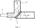
- Patent Literature 1 For effectively facilitated transformation of the urea water into ammonia, it is necessary to positively facilitate gasification of the urea water to proceed with substantive chemical reaction for ammonia production. It has been suggested by some of inventors in the present invention (see below-mentioned Patent Literature 1) that, as shown in Fig. 1 , a reactor d is located in a bent portion b (flow change portion where exhaust gas c flows curvedly) halfway in an exhaust pipe a; urea water f is sprayed from upstream by an injector e against the reactor d to impinge the sprayed urea water f on rectification vanes g of the reactor d for facilitated gasification thereof through heat receiving.
- a reactor d is located in a bent portion b (flow change portion where exhaust gas c flows curvedly) halfway in an exhaust pipe a; urea water f is sprayed from upstream by an injector e against the reactor d to impinge the sprayed urea water
- rectification vanes g are arrayed in a direction substantially bisecting an angle formed by inflow and outflow directions of the exhaust gas c flowing from upstream of and out downstream of the bent portion b (see arrows x and y in Fig. 1 ), respectively.
- Each of the rectification vanes g is mounted to take a mounted posture along the flow of the exhaust gas c flowing curvedly in the bent portion b and has a downstream fin h which guides the flow of the exhaust gas c to the outflow direction from the bent portion b to afford a rectification effect to the exhaust gas c flowing curvedly in the bent portion b.
- Patent Literature 1 JP 2015-218687A
- the invention was made in view of the above and has its object to provide a reactor which can be easily fabricated without needing to position rectification vanes by a jig.
- the invention is directed to a reactor located in a flow change portion through which exhaust gas in an exhaust system flows curvedly, an addition agent sprayed from upstream of said flow change portion being impinged against the reactor to facilitate gasification thereof through heat receiving, characterized in that it comprises a plurality of rectification vanes arrayed in a direction substantially bisecting an angle formed by inflow and outflow directions of the exhaust gas to and from said flow change portion and a support which supports opposite ends of each of said rectification vanes and is to be received in said flow change portion, said support being provided with a pair of opposite side walls each providing a slanting side in an arrayed direction of said rectification vanes, a plurality of slots being formed on each of said slanting sides of said opposite side walls, the opposite ends of each of said rectification vanes being inserted from upstream into said slots to provide an installed state, said rectification vanes in said installed state being adapted to provide mounted postures along the flow of the exhaust gas.
- each of the rectification vanes from upstream into the slots on the slanting sides of the opposite side walls of the support causes the vane to be simply installed while regulated to provide a mounted posture along the flow of the exhaust gas.
- the vanes can be arrayed and supported in the direction substantially bisecting the angle formed by the inflow and outflow directions of the exhaust gas into and from the flow change portion to provide the appropriate mounted postures.
- each of the rectification vanes has a downstream fin which guides the flow of the exhaust gas to the outflow direction from the flow change portion. Then, the flow of the exhaust gas rectified by passing thereof between the rectification vanes is smoothly guided by the fins to the outflow direction from the flow change portion.
- the support is provided with a downstream fixing ring to be fitted into a flow passage wall of the flow change portion. Then, the reactor is simply fixed by fitting the fixing ring into the flow passage wall of the flow change portion when the reactor preassembled from the rectification vanes and the support is received in the flow change portion for fixing.
- the reactor of the invention as mentioned in the above can exhibit various excellent effects as follows.
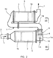
- Fig. 2 shows the embodiment of the invention applied to an exhaust emission control device detailed hereinafter. More specifically, in the exhaust emission control device to which the embodiment is applied, incorporated in an exhaust pipe 2 through which exhaust gas 1 from an engine flows and housed in casings 5 and 6 in parallel with each other are a particulate filer 3 for capturing particulates in the exhaust gas 1 and a selective reduction catalyst 4 downstream of the particulate filter 3 and having a property of selectively reacting NO x with ammonia even in the presence of oxygen, a communication passage 7 being provided to oppositely turn the exhaust gas 1 discharged from an exit side of the particulate filter 3 into an entry side of the adjacent selective reduction catalyst 4, a reactor 8 being applied to and arranged in a flow change portion most upstream in the communication passage 7.
- the communication passage 7 is an S-shaped structure comprising a gas gathering chamber 7A which encircles an exit end of the particulate filter 3 to gather the exhaust gas 1 discharged therefrom through substantially perpendicular turnabout of the gas, a communication pipe 7B which extracts the exhaust gas 1 gathered in the gas gathering chamber 7A from an exhaust outlet 9 into the entry side of the selective reduction catalyst 4 and a gas dispersion chamber 7c which encircles the entry side of the selective reduction catalyst 4 to disperse the exhaust gas 1 guided by the communication pipe 7B through substantially perpendicular turnabout of the gas into the entry side of the selective reduction catalyst 4.
- the exhaust outlet 9 of the gas gathering chamber 7A is opened directed slantly downward in an anglarily deviated manner from a direct downward direction of the gas gathering chamber 7A toward the selective reduction catalyst 4.
- An injector 11 is attached to the gas gathering chamber 7A on a slantly upward position opposed to the exhaust outlet 9 such that urea water 10 may be injected to the exhaust outlet 9.
- the exhaust outlet 9 of the gas gathering chamber 7A is provided with a reactor 8 against which the urea water 10 sprayed by the injector 11 is impinged for facilitated gasification thereof.
- the gas gathering chamber 7A which is most upstream in the communication passage 7 is the flow change portion (where the exhaust gas 1 flows curvedly) to which the reactor 8 in the embodiment is applied.
- the reactor 8 is provided with a plurality of rectification vanes 12 arrayed in a direction substantially bisecting an angle formed by inflow and outflow directions (see arrows x and y in Fig. 4 ) of the exhaust gas 1 into and from the gas gathering chamber 7A and a support 13 which supports opposite ends of each of the rectification vanes 12 and is to be received in the gas gathering chamber 7A.
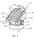
- the support 13 has a pair of opposite side walls 13a each providing a slanting side in the arrayed direction of the rectification vanes 12.
- a plurality of slots 14 are formed on each of the slanting sides of the opposite side walls 13a.
- each of the rectification vanes 12 are inserted from upstream into the slots 14 to provide an installed state; the rectification vanes 12 in the installed state are adapted to provide mounted postures (postures with less pressure loss set by flow analysis of the exhaust gas 1) along the flow of the exhaust gas 1; moreover, especially in the embodiment, each of the rectification vanes 12 except opposite ends thereof has a downstream fin 12a which guides the flow of the exhaust gas 1 to outflow direction from the gas gathering chamber 7A.
- the opposite side walls 13a are interconnected through a rear wall 13b which provides a shield face to the inflow direction of the exhaust gas 1 on a downstream side of the rectification vanes 12.
- a fixing ring 13c which is cylindrical in the outflow direction of the gas gathering chamber 7A and is to be fitted into a flow passage wall at the exhaust outlet 9 of the gas gathering chamber 7A.
- an oxidation catalyst 15 for oxidization treatment of unburned fuel components in the exhaust gas 1
- an ammonia reducing catalyst 16 for oxidization treatment of surplus ammonia.
- each of the rectification vanes 12 is inserted from upstream into the slots 14 formed on the slanting sides of the opposite side walls in the support 13 to insert the rectification vane 12 to be simply installed while regulated to provide a mounted posture along the flow of the exhaust gas 1; without needing to position the rectification vanes 12 using a jig, the vanes 12 can be arrayed and supported in a direction substantially bisecting an angle formed by inflow and outflow directions of the exhaust gas 1 to and from the gas gathering chamber 7A to provide the appropriate mounted postures.
- each of the rectification vanes 12 is provided with a downstream fin 12a which guides the flow of the exhaust gas 1 to the outflow direction from the gas gathering chamber 7A, so that the flow of the exhaust gas 1 rectified by passing thereof between the rectification vanes 12 is smoothly guided by the fins 12a to the outflow direction from the gas gathering chamber 7A.
- the support 13 is provided with the downstream fixing ring 13c which is to be fitted into the flow passage wall of the gas gathering chamber 7A, so that the reactor 4 can be simply fixed by fitting the fixing ring 13c into the flow passage wall of the gas gathering chamber 7A when the reactor 8 preassembled from the rectification vanes 12 and the support 13 is received in the flow passage wall of the gas gathering chamber 7A for fixing.
- the reactor 8 can be easily fabricated without needing to position the rectification vanes 12 by a jig upon arraying and supporting of the vanes 12 in the direction substantially bisecting the angle formed by the inflow and outflow directions of the exhaust gas 1 to and from the gas gathering chamber 7A.
- each of the rectification vanes 12 has a downstream fin 12a which guides the flow of the exhaust gas 1 to the outflow direction from the gas gathering chamber 7A, so that the flow of the exhaust gas 1 rectified by passing thereof between the rectification vanes 12 can be smoothly guided by the fins 12a to the outflow direction from the gas gathering chamber 7A, whereby the rectifying effect by the rectification vanes 12 can be further enhanced to further reduce the pressure loss.
- the support 13 is provided with the downstream fixing ring 13c to be fitted into the flow passage wall of the gas gathering chamber 7A, so that the reactor 8 can be simply fixed by fitting the fixing ring 13c into the flow passage wall of the gas gathering chamber 7A when the reactor 8 preassembled by the rectification vanes 12 and the support 13 is received in the gas gathering chamber 7A for fixing.
- a reactor according to the invention is not limited to the above embodiment and that various changes and modifications may be made without departing from the scope of the invention.
- the description has been made in the embodiment using Figs. 2-5 in a case where the addition agent is urea water; alternatively the addition agent may be fuel, provided that the selective reduction catalyst has a property of selectively reacting NO x with HC gas even in the presence of oxygen.
- the addition agent is not limited to that added as reducing agent upstream of the selective reduction catalyst; the invention may be applied to various addition agents which require gasification.
Landscapes
- Chemical & Material Sciences (AREA)
- Chemical Kinetics & Catalysis (AREA)
- Engineering & Computer Science (AREA)
- Health & Medical Sciences (AREA)
- Toxicology (AREA)
- Combustion & Propulsion (AREA)
- Mechanical Engineering (AREA)
- General Engineering & Computer Science (AREA)
- Dispersion Chemistry (AREA)
- Exhaust Gas After Treatment (AREA)
Abstract
Disclosed is a reactor 8 located in a gas gathering chamber 7A (flow change portion) through which exhaust gas 1 in an exhaust system flows curvedly. Urea water 10 (addition agent) sprayed against the reactor 8 from upstream of the chamber 7A to facilitate gasification through heat receiving. Provided are rectification vanes 12 arrayed in a direction bisecting an angle formed by inflow and outflow directions of the exhaust gas 1 (see arrows x and y) and a support 13 for supporting opposite ends of each of the vanes 12. Opposite ends of the vanes 12 are inserted into slots 14 on slanting sides of opposite side walls 13a in the support 13 to provide installed state. The vanes 12 in the installed state are adapted to provide mounted postures along the flow of the exhaust gas 1.
Description
- The present invention relates to a reactor against which an addition agent sprayed from upstream is impinged for facilitated gasification thereof through heat receiving.
- Conventionally, some diesel engines have a selective reduction catalyst incorporated in an exhaust pipe through which exhaust gas flows and having a property of selectively reacting NOx (nitrogen oxides) with a reducing agent even in the presence of oxygen. A required amount of reducing agent is added upstream of the selective reduction catalyst and is reductively reacted on the catalyst with NOx in the exhaust gas to thereby reduce a concentration of discharged NOx.
- Meanwhile, effectiveness of ammonia (NH3) used as a reducing agent for reduction and purification of NOx is well known in a field of industrial flue gas denitration in a plant or the like. However, in a field of automobile where safety is hard to assure as to running with ammonia itself being loaded, it has been proposed to use urea water as a reducing agent.
- Specifically, the urea water added into the exhaust gas upstream of the selective reduction catalyst is hydrolyzed into ammonia and carbon dioxide gas according to the following formula to satisfactorily depurate NOx in the exhaust gas through reduction on the catalyst by the ammonia.
(NH2)2CO + H2O → 2NH3 + CO2
- For effectively facilitated transformation of the urea water into ammonia, it is necessary to positively facilitate gasification of the urea water to proceed with substantive chemical reaction for ammonia production. It has been suggested by some of inventors in the present invention (see below-mentioned Patent Literature 1) that, as shown in
Fig. 1 , a reactor d is located in a bent portion b (flow change portion where exhaust gas c flows curvedly) halfway in an exhaust pipe a; urea water f is sprayed from upstream by an injector e against the reactor d to impinge the sprayed urea water f on rectification vanes g of the reactor d for facilitated gasification thereof through heat receiving. - Specifically, employed is a structure such that the rectification vanes g are arrayed in a direction substantially bisecting an angle formed by inflow and outflow directions of the exhaust gas c flowing from upstream of and out downstream of the bent portion b (see arrows x and y in
Fig. 1 ), respectively. - Each of the rectification vanes g is mounted to take a mounted posture along the flow of the exhaust gas c flowing curvedly in the bent portion b and has a downstream fin h which guides the flow of the exhaust gas c to the outflow direction from the bent portion b to afford a rectification effect to the exhaust gas c flowing curvedly in the bent portion b.
- Patent Literature 1:
JP 2015-218687A - However, such a conventional proposal merely conceptually explains an arrayed condition and mounted postures of the rectification vanes g and has no technically specific disclosure on how to support the rectification vanes g. Even if the rectification vanes g were to be fixed to a flow passage wall of the bent portion b simply by welding or the like, to array the rectification vanes g in the direction substantially bisecting the angle formed by the inflow and outflow directions of the exhaust gas c to and from the bent portion b to take appropriate mounted postures would require troublesome positioning of the rectification vanes g through some jig. Thus, it is feared that the reactor d cannot be easily fabricated.
- The invention was made in view of the above and has its object to provide a reactor which can be easily fabricated without needing to position rectification vanes by a jig.
- The invention is directed to a reactor located in a flow change portion through which exhaust gas in an exhaust system flows curvedly, an addition agent sprayed from upstream of said flow change portion being impinged against the reactor to facilitate gasification thereof through heat receiving, characterized in that it comprises a plurality of rectification vanes arrayed in a direction substantially bisecting an angle formed by inflow and outflow directions of the exhaust gas to and from said flow change portion and a support which supports opposite ends of each of said rectification vanes and is to be received in said flow change portion, said support being provided with a pair of opposite side walls each providing a slanting side in an arrayed direction of said rectification vanes, a plurality of slots being formed on each of said slanting sides of said opposite side walls, the opposite ends of each of said rectification vanes being inserted from upstream into said slots to provide an installed state, said rectification vanes in said installed state being adapted to provide mounted postures along the flow of the exhaust gas.
- Then, to insert the opposite ends of each of the rectification vanes from upstream into the slots on the slanting sides of the opposite side walls of the support causes the vane to be simply installed while regulated to provide a mounted posture along the flow of the exhaust gas. Thus, without needing to position the rectification vanes through a jig, the vanes can be arrayed and supported in the direction substantially bisecting the angle formed by the inflow and outflow directions of the exhaust gas into and from the flow change portion to provide the appropriate mounted postures.
- It is preferable in the invention that each of the rectification vanes has a downstream fin which guides the flow of the exhaust gas to the outflow direction from the flow change portion. Then, the flow of the exhaust gas rectified by passing thereof between the rectification vanes is smoothly guided by the fins to the outflow direction from the flow change portion.
- It is preferable in the invention that the support is provided with a downstream fixing ring to be fitted into a flow passage wall of the flow change portion. Then, the reactor is simply fixed by fitting the fixing ring into the flow passage wall of the flow change portion when the reactor preassembled from the rectification vanes and the support is received in the flow change portion for fixing.
- The reactor of the invention as mentioned in the above can exhibit various excellent effects as follows.
- (I) To insert the opposite ends of the rectification vanes into the slots on the slanting sides of the opposite side walls of the support can cause the vanes to be simply installed. The installation can cause the rectification vanes to be regulated to provide mounted postures along the flow of the exhaust gas. Thus, the reactor can be easily fabricated without needing to position the rectification vanes by a jig upon arraying and supporting of the vanes in the direction substantially bisecting the angle formed by the inflow and outflow directions of the exhaust gas into and from the flow change portion.
- (II) If each of the rectification vanes has the downstream fin which guides the flow of the exhaust gas to the outflow direction from the flow change portion, the flow of the exhaust gas rectified by passing thereof between the rectification vanes can be smoothly guided by the fins to the outflow direction of the flow change portion. Thus, the rectification effect by the rectification vanes can be further enhanced to further reduce the pressure loss.
- (III) If the support is provided with the downstream fixing ring to be fitted into the flow passage wall of the flow change portion, the reactor can be simply fixed by fitting the fixing ring into the flow passage wall of the flow change portion when the reactor preassembled from the rectification vanes and the support is received in the flow change portion for fixing.
-
-
Fig. 1 is a sectional view conceptually showing a conventional example; -
Fig. 2 is a schematic diagram showing an embodiment of the invention; -
Fig. 3 is a view looking in a direction of arrows III inFig. 2 ; -
Fig. 4 is a sectional view looking in a direction of arrows IV inFig. 3 ; and -
Fig. 5 is a perspective view showing particulars of a reactor shown inFig. 4 . - An embodiment of the invention will be described in conjunction with the drawings.
-
Fig. 2 shows the embodiment of the invention applied to an exhaust emission control device detailed hereinafter. More specifically, in the exhaust emission control device to which the embodiment is applied, incorporated in anexhaust pipe 2 through whichexhaust gas 1 from an engine flows and housed incasings particulate filer 3 for capturing particulates in theexhaust gas 1 and aselective reduction catalyst 4 downstream of theparticulate filter 3 and having a property of selectively reacting NOx with ammonia even in the presence of oxygen, acommunication passage 7 being provided to oppositely turn theexhaust gas 1 discharged from an exit side of theparticulate filter 3 into an entry side of the adjacentselective reduction catalyst 4, areactor 8 being applied to and arranged in a flow change portion most upstream in thecommunication passage 7. - Specifically, the
communication passage 7 is an S-shaped structure comprising agas gathering chamber 7A which encircles an exit end of theparticulate filter 3 to gather theexhaust gas 1 discharged therefrom through substantially perpendicular turnabout of the gas, acommunication pipe 7B which extracts theexhaust gas 1 gathered in thegas gathering chamber 7A from anexhaust outlet 9 into the entry side of theselective reduction catalyst 4 and a gas dispersion chamber 7c which encircles the entry side of theselective reduction catalyst 4 to disperse theexhaust gas 1 guided by thecommunication pipe 7B through substantially perpendicular turnabout of the gas into the entry side of theselective reduction catalyst 4. - As shown in
Fig. 3 , theexhaust outlet 9 of thegas gathering chamber 7A is opened directed slantly downward in an anglarily deviated manner from a direct downward direction of thegas gathering chamber 7A toward theselective reduction catalyst 4. Aninjector 11 is attached to thegas gathering chamber 7A on a slantly upward position opposed to theexhaust outlet 9 such thaturea water 10 may be injected to theexhaust outlet 9. Theexhaust outlet 9 of thegas gathering chamber 7A is provided with areactor 8 against which theurea water 10 sprayed by theinjector 11 is impinged for facilitated gasification thereof. - Here, as shown in
Fig. 4 , thegas gathering chamber 7A which is most upstream in thecommunication passage 7 is the flow change portion (where theexhaust gas 1 flows curvedly) to which thereactor 8 in the embodiment is applied. Thereactor 8 is provided with a plurality ofrectification vanes 12 arrayed in a direction substantially bisecting an angle formed by inflow and outflow directions (see arrows x and y inFig. 4 ) of theexhaust gas 1 into and from thegas gathering chamber 7A and asupport 13 which supports opposite ends of each of therectification vanes 12 and is to be received in thegas gathering chamber 7A. - Specifically as shown in
Fig. 5 , thesupport 13 has a pair ofopposite side walls 13a each providing a slanting side in the arrayed direction of therectification vanes 12. A plurality ofslots 14 are formed on each of the slanting sides of theopposite side walls 13a. Opposite ends of each of therectification vanes 12 are inserted from upstream into theslots 14 to provide an installed state; therectification vanes 12 in the installed state are adapted to provide mounted postures (postures with less pressure loss set by flow analysis of the exhaust gas 1) along the flow of theexhaust gas 1; moreover, especially in the embodiment, each of therectification vanes 12 except opposite ends thereof has adownstream fin 12a which guides the flow of theexhaust gas 1 to outflow direction from thegas gathering chamber 7A. - The
opposite side walls 13a are interconnected through arear wall 13b which provides a shield face to the inflow direction of theexhaust gas 1 on a downstream side of therectification vanes 12. Provided downstream of theopposite side walls 13a and therear wall 13b and integrally continuous therewith is afixing ring 13c which is cylindrical in the outflow direction of thegas gathering chamber 7A and is to be fitted into a flow passage wall at theexhaust outlet 9 of thegas gathering chamber 7A. - In the exhaust emission control device illustrated in
Fig. 2 , arranged in thecasing 5 upstream of theparticulate filter 3 is anoxidation catalyst 15 for oxidization treatment of unburned fuel components in theexhaust gas 1, and arranged in thecasting 6 downstream of theselective reduction catalyst 4 is anammonia reducing catalyst 16 for oxidization treatment of surplus ammonia. - With the
reactor 8 thus constructed, to insert the opposite ends of each of therectification vanes 12 from upstream into theslots 14 formed on the slanting sides of the opposite side walls in thesupport 13 causes therectification vane 12 to be simply installed while regulated to provide a mounted posture along the flow of theexhaust gas 1; without needing to position therectification vanes 12 using a jig, thevanes 12 can be arrayed and supported in a direction substantially bisecting an angle formed by inflow and outflow directions of theexhaust gas 1 to and from thegas gathering chamber 7A to provide the appropriate mounted postures. - Further, specifically in the embodiment, each of the
rectification vanes 12 is provided with adownstream fin 12a which guides the flow of theexhaust gas 1 to the outflow direction from thegas gathering chamber 7A, so that the flow of theexhaust gas 1 rectified by passing thereof between therectification vanes 12 is smoothly guided by thefins 12a to the outflow direction from thegas gathering chamber 7A. - Further, the
support 13 is provided with thedownstream fixing ring 13c which is to be fitted into the flow passage wall of thegas gathering chamber 7A, so that thereactor 4 can be simply fixed by fitting thefixing ring 13c into the flow passage wall of thegas gathering chamber 7A when thereactor 8 preassembled from therectification vanes 12 and thesupport 13 is received in the flow passage wall of thegas gathering chamber 7A for fixing. - Thus, according to the above embodiment, to insert the opposite ends of the
rectification vanes 12 into theslots 14 on the slanting sides of theopposite side walls 13a in thesupport 13 can cause thevanes 12 to be simply installed. The installation can cause the rectification vanes to be regulated to provide the mounted postures along the flow of the exhaust gas. Thus, thereactor 8 can be easily fabricated without needing to position therectification vanes 12 by a jig upon arraying and supporting of thevanes 12 in the direction substantially bisecting the angle formed by the inflow and outflow directions of theexhaust gas 1 to and from thegas gathering chamber 7A. - Further, each of the
rectification vanes 12 has adownstream fin 12a which guides the flow of theexhaust gas 1 to the outflow direction from thegas gathering chamber 7A, so that the flow of theexhaust gas 1 rectified by passing thereof between therectification vanes 12 can be smoothly guided by thefins 12a to the outflow direction from thegas gathering chamber 7A, whereby the rectifying effect by therectification vanes 12 can be further enhanced to further reduce the pressure loss. - Further, the
support 13 is provided with thedownstream fixing ring 13c to be fitted into the flow passage wall of thegas gathering chamber 7A, so that thereactor 8 can be simply fixed by fitting the fixingring 13c into the flow passage wall of thegas gathering chamber 7A when thereactor 8 preassembled by therectification vanes 12 and thesupport 13 is received in thegas gathering chamber 7A for fixing. - It is to be understood that a reactor according to the invention is not limited to the above embodiment and that various changes and modifications may be made without departing from the scope of the invention. For example, the description has been made in the embodiment using
Figs. 2-5 in a case where the addition agent is urea water; alternatively the addition agent may be fuel, provided that the selective reduction catalyst has a property of selectively reacting NOx with HC gas even in the presence of oxygen. The addition agent is not limited to that added as reducing agent upstream of the selective reduction catalyst; the invention may be applied to various addition agents which require gasification. -
- 1
- exhaust gas
- 7A
- gas gathering chamber (flow change portion)
- 8
- reactor
- 10
- urea water (addition agent)
- 12
- rectification vane
- 12a
- fin
- 13
- support
- 13a
- opposite side walls
- 13c
- fixing ring
- 14
- slot
Claims (3)
- A reactor located in a flow change portion through which exhaust gas in an exhaust system flows curvedly, an addition agent sprayed from upstream of said flow change portion being impinged against the reactor to facilitate gasification thereof through heat receiving, wherein it comprises a plurality of rectification vanes arrayed in a direction substantially bisecting an angle formed by inflow and outflow directions of the exhaust gas to and from said flow change portion and a support which supports opposite ends of each of said rectification vanes and is to be received in said flow change portion, said support being provided with a pair of opposite side walls each providing a slanting side in an arrayed direction of said rectification vanes, a plurality of slots being formed on each of said slanting sides of said opposite side walls, the opposite ends of each of said rectification vanes being inserted from upstream into said slots to provide an installed state, said rectification vanes in said installed state being adapted to provide mounted postures along the flow of the exhaust gas.
- The reactor as claimed in claim 1 wherein each of the rectification vanes has a downstream fin which guides the flow of the exhaust gas to the outflow direction from the flow change portion.
- The reactor as claimed in claim 1 or 2 wherein the support is provided with a downstream fixing ring to be fitted into a flow passage wall of the flow change portion.
Applications Claiming Priority (2)
| Application Number | Priority Date | Filing Date | Title |
|---|---|---|---|
| JP2017070919A JP6746529B2 (en) | 2017-03-31 | 2017-03-31 | Reactor |
| PCT/JP2018/009690 WO2018180457A1 (en) | 2017-03-31 | 2018-03-13 | Reactor |
Publications (1)
| Publication Number | Publication Date |
|---|---|
| EP3604755A1 true EP3604755A1 (en) | 2020-02-05 |
Family
ID=63675458
Family Applications (1)
| Application Number | Title | Priority Date | Filing Date |
|---|---|---|---|
| EP18777818.8A Withdrawn EP3604755A1 (en) | 2017-03-31 | 2018-03-13 | Reactor |
Country Status (5)
| Country | Link |
|---|---|
| US (1) | US20210108547A1 (en) |
| EP (1) | EP3604755A1 (en) |
| JP (1) | JP6746529B2 (en) |
| CN (1) | CN110446832A (en) |
| WO (1) | WO2018180457A1 (en) |
Family Cites Families (4)
| Publication number | Priority date | Publication date | Assignee | Title |
|---|---|---|---|---|
| DE102007021598B4 (en) * | 2007-05-08 | 2022-10-20 | Bayerische Motoren Werke Aktiengesellschaft | Device for distributing free-flowing additives in exhaust systems |
| KR101956731B1 (en) * | 2012-08-10 | 2019-03-12 | 테네코 오토모티브 오퍼레이팅 컴파니 인코포레이티드 | Method for mixing an exhaust gas flow |
| JP6282931B2 (en) * | 2014-05-20 | 2018-02-21 | 日野自動車株式会社 | Mixing structure |
| JP6535249B2 (en) * | 2015-08-07 | 2019-06-26 | 日野自動車株式会社 | Urea water reactor |
-
2017
- 2017-03-31 JP JP2017070919A patent/JP6746529B2/en active Active
-
2018
- 2018-03-13 US US16/498,524 patent/US20210108547A1/en not_active Abandoned
- 2018-03-13 CN CN201880022212.6A patent/CN110446832A/en active Pending
- 2018-03-13 EP EP18777818.8A patent/EP3604755A1/en not_active Withdrawn
- 2018-03-13 WO PCT/JP2018/009690 patent/WO2018180457A1/en not_active Ceased
Also Published As
| Publication number | Publication date |
|---|---|
| JP6746529B2 (en) | 2020-08-26 |
| WO2018180457A1 (en) | 2018-10-04 |
| US20210108547A1 (en) | 2021-04-15 |
| CN110446832A (en) | 2019-11-12 |
| JP2018173017A (en) | 2018-11-08 |
Similar Documents
| Publication | Publication Date | Title |
|---|---|---|
| US8813481B2 (en) | Exhaust emission control device | |
| US8347610B2 (en) | Exhaust emission control device | |
| EP2204556B1 (en) | Exhaust emission control device | |
| CN105378245B (en) | Mixer and emission cleaning module | |
| EP2192284A1 (en) | Exhaust purification apparatus | |
| EP2184455A1 (en) | Injector mounting structure | |
| CN105229273B (en) | Heat Shield and Emissions Cleaning Module | |
| EP3604754A1 (en) | Reactor | |
| EP2282028A1 (en) | Exhaust gas purification apparatus | |
| US10626767B2 (en) | Exhaust purification apparatus | |
| EP2549069B1 (en) | Exhaust gas purification device | |
| EP3168440A1 (en) | Mixing structure | |
| EP2857644B1 (en) | Mixing structure | |
| WO2009144509A1 (en) | System for treating a gas stream | |
| US20210108547A1 (en) | Reactor | |
| JP5950631B2 (en) | Exhaust purification device | |
| US20190292966A1 (en) | Mixing structure | |
| EP3594462A1 (en) | Exhaust gas purification apparatus |
Legal Events
| Date | Code | Title | Description |
|---|---|---|---|
| PUAI | Public reference made under article 153(3) epc to a published international application that has entered the european phase |
Free format text: ORIGINAL CODE: 0009012 |
|
| 17P | Request for examination filed |
Effective date: 20191001 |
|
| AK | Designated contracting states |
Kind code of ref document: A1 Designated state(s): AL AT BE BG CH CY CZ DE DK EE ES FI FR GB GR HR HU IE IS IT LI LT LU LV MC MK MT NL NO PL PT RO RS SE SI SK SM TR |
|
| AX | Request for extension of the european patent |
Extension state: BA ME |
|
| STAA | Information on the status of an ep patent application or granted ep patent |
Free format text: STATUS: THE APPLICATION HAS BEEN WITHDRAWN |
|
| 18W | Application withdrawn |
Effective date: 20200221 |