EP3604743A1 - Passive bleed valves with adjustable pressure threshold - Google Patents
Passive bleed valves with adjustable pressure threshold Download PDFInfo
- Publication number
- EP3604743A1 EP3604743A1 EP19189049.0A EP19189049A EP3604743A1 EP 3604743 A1 EP3604743 A1 EP 3604743A1 EP 19189049 A EP19189049 A EP 19189049A EP 3604743 A1 EP3604743 A1 EP 3604743A1
- Authority
- EP
- European Patent Office
- Prior art keywords
- baffle
- bleed valve
- set pin
- housing
- inlet
- Prior art date
- Legal status (The legal status is an assumption and is not a legal conclusion. Google has not performed a legal analysis and makes no representation as to the accuracy of the status listed.)
- Granted
Links
Images




Classifications
-
- F—MECHANICAL ENGINEERING; LIGHTING; HEATING; WEAPONS; BLASTING
- F04—POSITIVE - DISPLACEMENT MACHINES FOR LIQUIDS; PUMPS FOR LIQUIDS OR ELASTIC FLUIDS
- F04D—NON-POSITIVE-DISPLACEMENT PUMPS
- F04D27/00—Control, e.g. regulation, of pumps, pumping installations or pumping systems specially adapted for elastic fluids
- F04D27/02—Surge control
- F04D27/0207—Surge control by bleeding, bypassing or recycling fluids
- F04D27/0215—Arrangements therefor, e.g. bleed or by-pass valves
-
- F—MECHANICAL ENGINEERING; LIGHTING; HEATING; WEAPONS; BLASTING
- F01—MACHINES OR ENGINES IN GENERAL; ENGINE PLANTS IN GENERAL; STEAM ENGINES
- F01D—NON-POSITIVE DISPLACEMENT MACHINES OR ENGINES, e.g. STEAM TURBINES
- F01D17/00—Regulating or controlling by varying flow
- F01D17/10—Final actuators
- F01D17/105—Final actuators by passing part of the fluid
-
- F—MECHANICAL ENGINEERING; LIGHTING; HEATING; WEAPONS; BLASTING
- F01—MACHINES OR ENGINES IN GENERAL; ENGINE PLANTS IN GENERAL; STEAM ENGINES
- F01D—NON-POSITIVE DISPLACEMENT MACHINES OR ENGINES, e.g. STEAM TURBINES
- F01D17/00—Regulating or controlling by varying flow
- F01D17/10—Final actuators
- F01D17/12—Final actuators arranged in stator parts
- F01D17/14—Final actuators arranged in stator parts varying effective cross-sectional area of nozzles or guide conduits
- F01D17/141—Final actuators arranged in stator parts varying effective cross-sectional area of nozzles or guide conduits by means of shiftable members or valves obturating part of the flow path
- F01D17/145—Final actuators arranged in stator parts varying effective cross-sectional area of nozzles or guide conduits by means of shiftable members or valves obturating part of the flow path by means of valves, e.g. for steam turbines
-
- F—MECHANICAL ENGINEERING; LIGHTING; HEATING; WEAPONS; BLASTING
- F02—COMBUSTION ENGINES; HOT-GAS OR COMBUSTION-PRODUCT ENGINE PLANTS
- F02C—GAS-TURBINE PLANTS; AIR INTAKES FOR JET-PROPULSION PLANTS; CONTROLLING FUEL SUPPLY IN AIR-BREATHING JET-PROPULSION PLANTS
- F02C7/00—Features, components parts, details or accessories, not provided for in, or of interest apart form groups F02C1/00 - F02C6/00; Air intakes for jet-propulsion plants
- F02C7/26—Starting; Ignition
-
- F—MECHANICAL ENGINEERING; LIGHTING; HEATING; WEAPONS; BLASTING
- F02—COMBUSTION ENGINES; HOT-GAS OR COMBUSTION-PRODUCT ENGINE PLANTS
- F02C—GAS-TURBINE PLANTS; AIR INTAKES FOR JET-PROPULSION PLANTS; CONTROLLING FUEL SUPPLY IN AIR-BREATHING JET-PROPULSION PLANTS
- F02C9/00—Controlling gas-turbine plants; Controlling fuel supply in air- breathing jet-propulsion plants
- F02C9/16—Control of working fluid flow
- F02C9/18—Control of working fluid flow by bleeding, bypassing or acting on variable working fluid interconnections between turbines or compressors or their stages
-
- F—MECHANICAL ENGINEERING; LIGHTING; HEATING; WEAPONS; BLASTING
- F04—POSITIVE - DISPLACEMENT MACHINES FOR LIQUIDS; PUMPS FOR LIQUIDS OR ELASTIC FLUIDS
- F04D—NON-POSITIVE-DISPLACEMENT PUMPS
- F04D27/00—Control, e.g. regulation, of pumps, pumping installations or pumping systems specially adapted for elastic fluids
- F04D27/02—Surge control
- F04D27/0207—Surge control by bleeding, bypassing or recycling fluids
- F04D27/0223—Control schemes therefor
-
- F—MECHANICAL ENGINEERING; LIGHTING; HEATING; WEAPONS; BLASTING
- F04—POSITIVE - DISPLACEMENT MACHINES FOR LIQUIDS; PUMPS FOR LIQUIDS OR ELASTIC FLUIDS
- F04D—NON-POSITIVE-DISPLACEMENT PUMPS
- F04D27/00—Control, e.g. regulation, of pumps, pumping installations or pumping systems specially adapted for elastic fluids
- F04D27/02—Surge control
- F04D27/0207—Surge control by bleeding, bypassing or recycling fluids
- F04D27/023—Details or means for fluid extraction
-
- F—MECHANICAL ENGINEERING; LIGHTING; HEATING; WEAPONS; BLASTING
- F16—ENGINEERING ELEMENTS AND UNITS; GENERAL MEASURES FOR PRODUCING AND MAINTAINING EFFECTIVE FUNCTIONING OF MACHINES OR INSTALLATIONS; THERMAL INSULATION IN GENERAL
- F16K—VALVES; TAPS; COCKS; ACTUATING-FLOATS; DEVICES FOR VENTING OR AERATING
- F16K1/00—Lift valves or globe valves, i.e. cut-off apparatus with closure members having at least a component of their opening and closing motion perpendicular to the closing faces
- F16K1/12—Lift valves or globe valves, i.e. cut-off apparatus with closure members having at least a component of their opening and closing motion perpendicular to the closing faces with streamlined valve member around which the fluid flows when the valve is opened
- F16K1/126—Lift valves or globe valves, i.e. cut-off apparatus with closure members having at least a component of their opening and closing motion perpendicular to the closing faces with streamlined valve member around which the fluid flows when the valve is opened actuated by fluid
-
- F—MECHANICAL ENGINEERING; LIGHTING; HEATING; WEAPONS; BLASTING
- F16—ENGINEERING ELEMENTS AND UNITS; GENERAL MEASURES FOR PRODUCING AND MAINTAINING EFFECTIVE FUNCTIONING OF MACHINES OR INSTALLATIONS; THERMAL INSULATION IN GENERAL
- F16K—VALVES; TAPS; COCKS; ACTUATING-FLOATS; DEVICES FOR VENTING OR AERATING
- F16K15/00—Check valves
- F16K15/02—Check valves with guided rigid valve members
- F16K15/025—Check valves with guided rigid valve members the valve being loaded by a spring
- F16K15/026—Check valves with guided rigid valve members the valve being loaded by a spring the valve member being a movable body around which the medium flows when the valve is open
-
- F—MECHANICAL ENGINEERING; LIGHTING; HEATING; WEAPONS; BLASTING
- F02—COMBUSTION ENGINES; HOT-GAS OR COMBUSTION-PRODUCT ENGINE PLANTS
- F02C—GAS-TURBINE PLANTS; AIR INTAKES FOR JET-PROPULSION PLANTS; CONTROLLING FUEL SUPPLY IN AIR-BREATHING JET-PROPULSION PLANTS
- F02C6/00—Plural gas-turbine plants; Combinations of gas-turbine plants with other apparatus; Adaptations of gas-turbine plants for special use
- F02C6/04—Gas-turbine plants providing heated or pressurised working fluid for other apparatus, e.g. without mechanical power output
- F02C6/06—Gas-turbine plants providing heated or pressurised working fluid for other apparatus, e.g. without mechanical power output providing compressed gas
- F02C6/08—Gas-turbine plants providing heated or pressurised working fluid for other apparatus, e.g. without mechanical power output providing compressed gas the gas being bled from the gas-turbine compressor
-
- F—MECHANICAL ENGINEERING; LIGHTING; HEATING; WEAPONS; BLASTING
- F05—INDEXING SCHEMES RELATING TO ENGINES OR PUMPS IN VARIOUS SUBCLASSES OF CLASSES F01-F04
- F05D—INDEXING SCHEME FOR ASPECTS RELATING TO NON-POSITIVE-DISPLACEMENT MACHINES OR ENGINES, GAS-TURBINES OR JET-PROPULSION PLANTS
- F05D2270/00—Control
- F05D2270/01—Purpose of the control system
- F05D2270/10—Purpose of the control system to cope with, or avoid, compressor flow instabilities
-
- F—MECHANICAL ENGINEERING; LIGHTING; HEATING; WEAPONS; BLASTING
- F05—INDEXING SCHEMES RELATING TO ENGINES OR PUMPS IN VARIOUS SUBCLASSES OF CLASSES F01-F04
- F05D—INDEXING SCHEME FOR ASPECTS RELATING TO NON-POSITIVE-DISPLACEMENT MACHINES OR ENGINES, GAS-TURBINES OR JET-PROPULSION PLANTS
- F05D2270/00—Control
- F05D2270/01—Purpose of the control system
- F05D2270/10—Purpose of the control system to cope with, or avoid, compressor flow instabilities
- F05D2270/101—Compressor surge or stall
-
- F—MECHANICAL ENGINEERING; LIGHTING; HEATING; WEAPONS; BLASTING
- F05—INDEXING SCHEMES RELATING TO ENGINES OR PUMPS IN VARIOUS SUBCLASSES OF CLASSES F01-F04
- F05D—INDEXING SCHEME FOR ASPECTS RELATING TO NON-POSITIVE-DISPLACEMENT MACHINES OR ENGINES, GAS-TURBINES OR JET-PROPULSION PLANTS
- F05D2270/00—Control
- F05D2270/30—Control parameters, e.g. input parameters
- F05D2270/301—Pressure
- F05D2270/3015—Pressure differential pressure
-
- F—MECHANICAL ENGINEERING; LIGHTING; HEATING; WEAPONS; BLASTING
- F05—INDEXING SCHEMES RELATING TO ENGINES OR PUMPS IN VARIOUS SUBCLASSES OF CLASSES F01-F04
- F05D—INDEXING SCHEME FOR ASPECTS RELATING TO NON-POSITIVE-DISPLACEMENT MACHINES OR ENGINES, GAS-TURBINES OR JET-PROPULSION PLANTS
- F05D2270/00—Control
- F05D2270/40—Type of control system
- F05D2270/42—Type of control system passive or reactive, e.g. using large wind vanes
-
- F—MECHANICAL ENGINEERING; LIGHTING; HEATING; WEAPONS; BLASTING
- F05—INDEXING SCHEMES RELATING TO ENGINES OR PUMPS IN VARIOUS SUBCLASSES OF CLASSES F01-F04
- F05D—INDEXING SCHEME FOR ASPECTS RELATING TO NON-POSITIVE-DISPLACEMENT MACHINES OR ENGINES, GAS-TURBINES OR JET-PROPULSION PLANTS
- F05D2270/00—Control
- F05D2270/60—Control system actuates means
- F05D2270/65—Pneumatic actuators
-
- Y—GENERAL TAGGING OF NEW TECHNOLOGICAL DEVELOPMENTS; GENERAL TAGGING OF CROSS-SECTIONAL TECHNOLOGIES SPANNING OVER SEVERAL SECTIONS OF THE IPC; TECHNICAL SUBJECTS COVERED BY FORMER USPC CROSS-REFERENCE ART COLLECTIONS [XRACs] AND DIGESTS
- Y02—TECHNOLOGIES OR APPLICATIONS FOR MITIGATION OR ADAPTATION AGAINST CLIMATE CHANGE
- Y02T—CLIMATE CHANGE MITIGATION TECHNOLOGIES RELATED TO TRANSPORTATION
- Y02T50/00—Aeronautics or air transport
- Y02T50/60—Efficient propulsion technologies, e.g. for aircraft
Definitions
- the present disclosure relates to valves, and more particularly to inline bleed valves and methods of controlling fluid flow through bleed valves such as in gas turbine engines.
- Gas turbine engines such as on aircraft, commonly employ compressors.
- the compressor provides a flow of compressed fluid for combustion and subsequent expansion of high pressure combustion products in the engine turbine.
- the turbine extracts work from the expanding combustion products to provide power to the compressor during steady state operation.
- Venting is typically accomplished by opening a bleed valve, opening the compressor at least partially open to the external environment until fluid moving through the compressor section reaches suitable pressure. Open and closure of bleed valves is generally accomplished actively, such as by energizing or de-energizing a solenoid, or other commanded device.
- a bleed valve includes a housing with an inlet coupled to an outlet by a duct, a guide tube with an orifice fixed in the housing between the inlet and the outlet, a piston, and baffle.
- the piston is slideably supported on the guide tube and is movable between an open and a closed position, the duct fluidly coupling the inlet and outlet in the open position, the duct fluidly separating the inlet and outlet in the closed position.
- the orifice fluidly couples the inlet and outlet in the open and closed positions to move piston between the open and closed positions according to differential pressure between the bleed valve inlet and outlet.
- the baffle is slideably supported by the guide tube to set the differential pressure at which the piston moves between the open and closed positions.
- the baffle can extend circumferentially about an interior of the guide tube.
- the baffle can have a first position and a second position. Flow area of orifice can be larger in the second position than in the first position.
- the baffle can have a skirt portion and a face portion. The skirt portion can overlap a portion of the orifice in the first position.
- the face portion can of the baffle can be arranged within an interior of the guide post. The face portion can have a set pin aperture to seat a set pin in the baffle.
- the bleed valve can include a set pin.
- the set pin can movably couple the baffle to the housing for displacement of the baffle relative to the guide tube.
- a collar can be connected to the set pin and fix the baffle to the set pin.
- the set pin can have a flange arranged on the set pin adjacent the baffle and fix the baffle to the set pin.
- the housing can have a set pin aperture. The set pin can be received within the set pin aperture. The set pin can be free for rotation and axial movement relative to the housing for setting the differential pressure.
- a sleeve threadably seated in the set pin aperture can be received within the sleeve.
- the set pin can be threadably coupled to the sleeve for rotation and displacement relative to sleeve when moving between the first position and the second position.
- the set pin can have a set pin has a tool engagement feature arranged on an end of the set pin opposite the baffle.
- the orifice can include a plurality of axially extending slots.
- the baffle can overlap the axially extending slots in at least one of the first position and the second position.
- the housing can have a housing orifice fluidly coupling the guide tube orifice with the bypass channel,
- the set pin can be arranged between guide tube orifice and the housing aperture.
- a gas turbine engine includes a compressor with a plenum, a turbine operably connected to the compressor, and bleed valve as described above.
- the bleed valve couples the plenum with the external environment and includes a set pin movably coupling the baffle to the housing for displacement of the baffle relative to the guide tube.
- the set pin is threadably coupled to the housing for rotation and displacement relative to sleeve to set the differential pressure.
- the housing can have a housing aperture fluidly coupling the guide tube orifice with the bypass channel, the set pin arranged between guide tube orifice and the housing aperture.
- a method of setting differential pressure at which a bleed valve opens includes setting the differential pressure between the inlet and the outlet of the bleed valve at which the piston moves between an open position and a closed position.
- the piston moves to the closed position such that the duct fluidly separates the inlet from the outlet.
- the differential pressure drops blow above the differential pressure the piston moves to the open position such that the duct fluidly couples the inlet to the outlet.
- setting the differential pressure can include rotating a set pin connecting the baffle to the housing. Setting the differential pressure can include changing flow area of the orifice.
- a partial view of an exemplary embodiment of a bleed valve in accordance with the disclosure is shown in Fig. 1 and is designated generally by reference character 100.
- Other embodiments of bleed valves, compressors, gas turbine engines, and methods a controlling fluid flow through bleed valves in accordance with the disclosure, or aspects thereof, are provided in Figs. 2-9 , as will be described.
- the systems and methods described herein can be used for passively controlling inline bleed valves in gas turbine engines, though the present disclosure is not limited to gas turbine engines in general.
- Gas turbine engine 10 includes case 12 containing a compressor section 14, a combustion section 16, and a turbine section 18.
- Compressor section 14 is disposed in fluid communication with external environment 20 and is arranged to compress fluid 22 ingested from external environment 20. Once compressed fluid 22 is communicated to combustion section 16 as a compressed fluid 24.
- Combustion section 16 is disposed in fluid communication with compressor section 14, is arranged to receive therefrom compressed fluid 24, and generates high pressure combustion products 26 using compressed fluid 24 and fuel also provided to combustion section 16. High pressure combustion products 26 are provided by combustion section 16 to turbine section 18.
- Turbine section 18 is disposed in fluid communication with combustion section 16 and is arranged to receive therefrom high pressure combustion products 26. Turbine section 18 expands high pressure combustion products 26 as high pressure combustion products 26 traverse turbine section 18, turbine section 18 extracting work 28 from high pressure combustion products 26 during expansion. A portion of work 28 is provided to compressor section 14 to provide the input power necessary to compress fluid 22 for generating compressed fluid 24, the amount of work corresponding the amount of fluid and extent of compression required for the operating state of gas turbine engine 10. Bleed valve 100 is connected to case 12 for reducing amount of work 28 provided to compressor section 14 according to the operating regime of gas turbine engine 10.
- compressor section 14 and bleed valve 100 are shown.
- Bleed valve 100 is fixed to case 12 for selectively (shown with the dashed flow arrow in Fig. 2 ) venting compressor section 14 to external environment 20.
- Compressor section 14 includes a plenum 30 which is in fluid communication with the gas path through compressor section 14 and is occupied by compressed fluid 24.
- An inlet 104 of bleed valve 100 is in fluid communication with plenum 30 such that differential in pressure P1 at inlet 104 (shown in Fig. 3A ) and pressure P3 at outlet 106 (shown in Fig. 3A ) of bleed valve 100.
- Differential between pressure P1 of compressed fluid 24 and P3 at outlet 106, i.e., differential pressure P1-P3 is used to passively operate bleed valve 100.
- bleed valve 100 includes a housing 102 with an inlet 104 coupled to an outlet 106 by a duct 108.
- Guide tube 110 with a guide tube orifice 134 is fixed in housing 102 between inlet 104 and outlet 106, a piston 112, and baffle 162.
- Piston 112 has a piston orifice 114, is slideably supported on guide tube 110, and is movable between an open position 116 (shown in Fig. 4 ) and a closed position 118 (shown in Fig. 5 ).
- Duct 108 fluidly couples inlet 104 with outlet 106 in open position 116.
- Duct 108 fluidly separates inlet 104 from outlet 106 in closed position 118.
- Guide tube orifice 134 and piston orifice 114 fluidly couple inlet 104 and outlet 106 in both open position 116 and closed position 118 to move piston 112 between open position 116 and closed position 118 according to differential pressure P1-P3 between bleed valve inlet 104 and outlet 106.
- Baffle 162 is slideably supported by guide tube 110 to set the differential pressure P1-P3 at which piston 112 moves between open position 116 and closed position 118.
- Outlet 106 can go to either the ambient environment or to a low pressure bypass flow stream, as suitable for an intended application.
- Housing 102 has an inlet portion 120 and an outlet portion 122.
- Inlet portion 120 defines inlet 104, is sealably connected to outlet portion 122 on an end opposite of inlet portion 120 opposite (relative to a direction of flow through bleed valve 100) inlet 104, and has an open seat 124 arranged within an interior of inlet portion 120. Open seat 124 is configured to receive piston 112 when piston 112 is in open position 116 (shown in Fig. 4 ).
- Outlet portion 122 defines outlet 106 and fastens to inlet portion 120 on an end of outlet portion 122 opposite (relative to a direction of flow through bleed valve 100) inlet 104.
- a closed seat 126 is arranged with an interior of outlet portion 122 to receive and sealably seat piston 112 when piston 112 is in closed position 118.
- Connection of inlet portion 120 to outlet portion 122 can be with threaded fasteners or any other type of suitable fixation.
- Guide tube 110 extends axially between inlet 104 and outlet 106 and has an inlet end 130, an outlet end 132, and a guide tube orifice 134.
- Outlet end 132 is seated in outlet portion 122 of housing 102.
- Guide tube orifice 134 is defined within guide tube 110 at a location between outlet end 132 and inlet end 130 and extends through a thickness of the wall defining guide tube 110.
- Inlet end 130 opposes inlet 104 on a side of guide tube orifice 134 opposite outlet end 132.
- An end cap 150 is seated on guide tube 110 facing inlet 104 separating an interior 164 of guide tube 110 from inlet 104.
- guide tube orifice 134 is one of plurality of guide tube orifices 134 defined between inner and outer surfaces of guide tube 110.
- Piston 112 is slidably seated on guide tube 110 and has a face 136 and a skirt 138. Face 136 opposes inlet 104. Skirt 138 extends from face 136 towards outlet 106 and has an inner portion 140 and an outer portion 142. Inner portion 140 extends about guide tube 110 and is in sliding engagement with an outer surface of guide tube 110. Outer portion 142 extends about inner portion 140 is sealably received between inlet portion 120 and outlet portion 122 of housing 102. Piston orifice 114 extends through piston face 136 to fluidly couple inlet 104 with a volume bounded by the downstream surface of face 136 and opposing faces of inner portion 140 and outer portion 142 of skirt 138.
- An inner sealing member 144 is seated within outer portion 122 of housing 102, extends about guide tube 110, and abuts an inner surface of outer portion 142 to prevent fluid flow therebetween.
- An outer sealing member 146 is seated within inlet portion 120 of housing 102, extends about skirt outer portion 142, and abuts an outer surface of skirt outer portion 142 to prevent fluid flow therebetween.
- Skirt 138 is slideably received between inner sealing member 144 and outer sealing member 146 to sealably move between open position 116 (shown in Fig. 4 ) and closed position 118 (shown in Fig. 5 ).
- a biasing member 148 is arranged between piston 112 and housing 102. Biasing member 148 is arranged to exert a biasing force B (shown in Fig. 4 ) on piston 112, biasing force B urging piston 112 in the direction of inlet 104 and toward open seat 124. It is contemplated that biasing force B cooperate with pressure P2 to exert a chamber pressure force C (shown in Fig. 4 ) on piston 112. Biasing force B and chamber pressure force C cooperate to oppose a plenum fluid force P (shown in Fig. 4 ) exerted on piston 112 by compressed fluid 24 (shown in Fig. 1 ), plenum fluid force P always being equivalent to or greater than chamber pressure force C.
- biasing member 148 includes a spring element arranged between an inner surface of piston face 136 and outlet portion 122 of housing 102.
- spring element arrangements and/or types of biasing elements can be used and remain within the scope of the present disclosure, as suitable for an intended application.
- piston 112 is shown subsequent to movement to open position 116.
- open position 116 piston 112 abuts open seat 124.
- Movement of piston 112 against open seat 124 such that piston 112 abuts open seat 124 withdraws skirt 138, and more particularly outer portion 142 of skirt 138, from duct 108.
- Withdrawal of skirt 138 causes duct 108 to fluidly couple inlet 104 with outlet 106, compressed fluid 24 thereby flowing through duct 108 such that pressurized fluid flows through bleed valve 100, venting plenum 30 to the external environment 20 or a low pressure bypass duct.
- Piston 112 remains in abutment with open seat 124 while differential pressure P1-P3 remains below the predetermined value.
- differential pressure P1-P3 across bleed valve 100 exceeds the predetermined differential pressure valve piston 112 moves to closed position 118 (shown in Fig. 5 ).
- piston 112 is shown subsequent to movement to closed position 118.
- closed position 118 piston abuts closed seat 126.
- Movement of piston 112 such that piston 112 abuts closed seat 126 introduces skirt 138, and more particularly skirt outer portion 14, into duct 108. Insertion of skirt 138 into duct 108 in turn causes duct 108 to fluidly separate inlet 104 from outlet 106, substantially no compressed fluid 24 thereby passing between inlet 104 and outlet 106 through duct 108.
- piston 112 remain in abutment with closed seat 126 while the differential pressure P1-P3 across bleed valve 100 remains above the predetermined value.
- the predetermined value demarcates a transition between starting and steady-state operation of a compressor, e.g., compressor section 14 (shown in Fig. 1 ) of gas turbine engine 10 (shown in Fig. 1 ).
- a piston 112 moves to an open position 116 (shown in Fig. 4 ). Movement of piston 112 to open position allows compressed fluid 24 to flow from plenum 30 to external environment 20 through a duct 108 within bleed valve 100.
- a piston 112 moves to a closed position 118 (shown in Fig. 5 ). Movement of piston 112 to closed position causes piston 112 to block duct 108 such that duct 108 fluidly separates outlet 106 from inlet 104.
- outlet 106 and inlet 104 are in fluid communication with one another through piston orifice 114 and guide tube orifice 134. Fluid communication through piston orifice 114 and guide tube orifice 134 causes compressed fluid 24 to flow through bleed valve 100 in both open position 116 and closed position 118, as shown with flow arrows passing through piston orifice 114 and guide tube orifice 134 in Figs. 4 and 5 .
- the differential pressure P1-P3 at which piston 112 moves between open position 116 and closed position 118 is determined by the minimum flow area within an orifice network 114/116 including piston orifice 114 and guide tube orifice 134.
- flow area 158 of guide tube orifice 134 defines the minimum flow area within orifice network 114/116.
- Flow area 158 is in turn defined by the position of baffle 162 relative guide tube orifice 134, thereby providing adjustability according to flow area of guide tube orifice 134. This is illustrated schematically in Fig.
- baffle 162 has a face portion 166 with a set pin aperture 169 and a skirt portion 171, is slideably supported by guide tube 110, and is operably associated with set mechanism 164 to set the differential pressure P1-P3 at which piston 112 moves between open position 116 (shown in Fig. 4 ) and closed position 118 (shown in Fig. 5 ).
- baffle 162 extends circumferentially about an interior surface of guide tube 110 and has a first position 168 (shown in Fig. 6 ) and a second position 170 (shown in Fig. 7 ).
- Skirt portion 171 radially bounds guide tube orifices 134, which each extend axially along a portion of the length of guide tube 110, in either (or both) first position 168 and second position 170.
- Flow area 158 (shown in Fig. 3B ) of guide tube orifice 134 is larger in second position 170 (shown with the dashed outline bounding flow area 158 in Fig. 3B ) than in first position 168 (shown with the dotted outline bounding flow area 158 in Fig. 3B ).
- piston 112 moves between open position 116 (shown in Fig. 4 ) to closed position 118 (shown in Fig. 5 ) at differential pressure A (shown in Fig. 8 ).
- baffle 162 is in second position 170 piston 112 moves between open position 116 and closed position 118 at differential pressure B.
- Operable connection of set mechanism 164 with baffle 162 allows for selection of differential pressure at which bleed valve 100 opens. This allows bleed valve 100 to be used on engines requiring actuation at different pressure differentials. It is contemplated that adjustability of baffle 112 be continuous, meaning that position of baffle 162 can be selected such bleed valve 100 moves between open position 116 and closed position 118 at any differential pressure between differential pressure A and differential B.
- set mechanism 164 includes a set pin 172 with a flange 174, a collar 176, and a sleeve 178.
- Set pin 172 movably couples baffle to the housing for displacement of the baffle relative to the guide tube.
- Flange 174 extends about set pin 172 adjacent baffle 162 and fixes baffle 162 to set pin 172.
- Collar 176 threadably seats about an end of set pin 172 and fixes baffle 162 to set pin 172.
- Set pin 172 is in turn received within a set pin aperture 181 defined within housing 102, set pin 172 arranged between guide tube orifice 134 and housing aperture 182 fluidly coupling guide tube orifice 134 with outlet 106, and set pin 172 being free for rotation and axial movement (both shown with arrows in Fig. 7 ) within sleeve 178 and relative to housing 102 for setting differential pressure P1-P3.
- this provide adjustability to bleed valve 100 by allowing differential pressure P1-P3 to be adjusted for needs of the particulate type (or serial number) of gas turbine engine. Physical adjustment can be accomplished, for example, via a tool engagement feature 180 arranged on an end of set pin 172 opposite baffle 162.
- Method 200 includes setting the differential pressure between the inlet and the outlet of the bleed valve at which the piston moves between an open position and a closed position, e.g., differential pressure P-P3 (shown in Fig. 4 ), as shown with box 210.
- a piston of the bleed valve e.g., piston 112 (shown in Fig. 3A ) moves to the closed position, e.g., closed position 118 (shown in Fig. 5 ), as shown with box 220.
- movement between the open position and the closed position can be passive, i.e., without the employment of a solenoid or muscle force from a pressurized fluid source, as shown box 222 and 232.
- setting the differential pressure can include rotating a set pin, e.g., set pin 172 (shown in Fig. 7 ) connecting the baffle to the bleed valve housing, thereby changing flow area of the orifice, as shown with box 212.
- Inline bleed valves for gas turbine engines are generally operated by a pneumatic controller.
- the pneumatic controller controls so-called muscle pressure to the inline bleed valve, applying the muscle pressure into a actuation chamber to actuate the inline bleed valve. While generally acceptable for their intended function such pneumatic controllers and actuation chambers can add complexity, mass, and/or size to the inline bleed valve.
- passive inline bleed valves function solely according to the pressure at bleed valve inlet and outlet.
- the bleed valve can include an orifice network with orifices defined within the inline bleed valve and fluidly between the inlet and the outlet.
- inline bleed valves with superior properties including passive control. Being passively controlled the inline bleed valves do not require an active control mechanism, such as a solenoid and/or a controller. This can reduce complexity, mass, and size of the bleed valve, potentially improving reliability and/or reducing cost. While the apparatus and methods of the subject disclosure have been shown and described with reference to preferred embodiments, those skilled in the art will readily appreciate that changes and/or modifications may be made thereto without departing from the scope of the subject disclosure.
Landscapes
- Engineering & Computer Science (AREA)
- General Engineering & Computer Science (AREA)
- Mechanical Engineering (AREA)
- Chemical & Material Sciences (AREA)
- Combustion & Propulsion (AREA)
- Life Sciences & Earth Sciences (AREA)
- Sustainable Development (AREA)
- Physics & Mathematics (AREA)
- Fluid Mechanics (AREA)
- Fluid-Driven Valves (AREA)
Abstract
Description
- This invention was made with government support with the United States Air Force under Contract No. FA8626-16-C-2139. The government has certain rights in the invention.
- The present disclosure relates to valves, and more particularly to inline bleed valves and methods of controlling fluid flow through bleed valves such as in gas turbine engines.
- Gas turbine engines, such as on aircraft, commonly employ compressors. The compressor provides a flow of compressed fluid for combustion and subsequent expansion of high pressure combustion products in the engine turbine. The turbine extracts work from the expanding combustion products to provide power to the compressor during steady state operation.
- During engine starting the power available from combustion products can be limited. In some engines, for purposes of limiting the work input requirement of the compressor during starting, the compressor is vented. Venting is typically accomplished by opening a bleed valve, opening the compressor at least partially open to the external environment until fluid moving through the compressor section reaches suitable pressure. Open and closure of bleed valves is generally accomplished actively, such as by energizing or de-energizing a solenoid, or other commanded device.
- Such conventional methods and systems have generally been considered satisfactory for their intended purpose. However, there is still a need in the art for improved bleed valves, compressors, gas turbine engines, and methods of controlling fluid flow through a bleed valve. The present disclosure provides a solution for this need.
- A bleed valve includes a housing with an inlet coupled to an outlet by a duct, a guide tube with an orifice fixed in the housing between the inlet and the outlet, a piston, and baffle. The piston is slideably supported on the guide tube and is movable between an open and a closed position, the duct fluidly coupling the inlet and outlet in the open position, the duct fluidly separating the inlet and outlet in the closed position. The orifice fluidly couples the inlet and outlet in the open and closed positions to move piston between the open and closed positions according to differential pressure between the bleed valve inlet and outlet. The baffle is slideably supported by the guide tube to set the differential pressure at which the piston moves between the open and closed positions.
- In certain embodiments the baffle can extend circumferentially about an interior of the guide tube. The baffle can have a first position and a second position. Flow area of orifice can be larger in the second position than in the first position. The baffle can have a skirt portion and a face portion. The skirt portion can overlap a portion of the orifice in the first position. The face portion can of the baffle can be arranged within an interior of the guide post. The face portion can have a set pin aperture to seat a set pin in the baffle.
- In accordance with certain embodiments the bleed valve can include a set pin. The set pin can movably couple the baffle to the housing for displacement of the baffle relative to the guide tube. A collar can be connected to the set pin and fix the baffle to the set pin. The set pin can have a flange arranged on the set pin adjacent the baffle and fix the baffle to the set pin. The housing can have a set pin aperture. The set pin can be received within the set pin aperture. The set pin can be free for rotation and axial movement relative to the housing for setting the differential pressure.
- It is contemplated that a sleeve threadably seated in the set pin aperture. The set pin can be received within the sleeve. The set pin can be threadably coupled to the sleeve for rotation and displacement relative to sleeve when moving between the first position and the second position. The set pin can have a set pin has a tool engagement feature arranged on an end of the set pin opposite the baffle. The orifice can include a plurality of axially extending slots. The baffle can overlap the axially extending slots in at least one of the first position and the second position. The housing can have a housing orifice fluidly coupling the guide tube orifice with the bypass channel, The set pin can be arranged between guide tube orifice and the housing aperture.
- A gas turbine engine includes a compressor with a plenum, a turbine operably connected to the compressor, and bleed valve as described above. The bleed valve couples the plenum with the external environment and includes a set pin movably coupling the baffle to the housing for displacement of the baffle relative to the guide tube. The set pin is threadably coupled to the housing for rotation and displacement relative to sleeve to set the differential pressure. In certain embodiments the housing can have a housing aperture fluidly coupling the guide tube orifice with the bypass channel, the set pin arranged between guide tube orifice and the housing aperture.
- A method of setting differential pressure at which a bleed valve opens includes setting the differential pressure between the inlet and the outlet of the bleed valve at which the piston moves between an open position and a closed position. When the differential pressure rises above the differential pressure the piston moves to the closed position such that the duct fluidly separates the inlet from the outlet. When the differential pressure drops blow above the differential pressure the piston moves to the open position such that the duct fluidly couples the inlet to the outlet.
- In certain embodiments movement between the open position and the closed position can be passive. Setting the differential pressure can include rotating a set pin connecting the baffle to the housing. Setting the differential pressure can include changing flow area of the orifice.
- These and other features of the systems and methods of the subject disclosure will become more readily apparent to those skilled in the art from the following detailed description of the preferred embodiments taken in conjunction with the drawings.
- So that those skilled in the art to which the subject disclosure appertains will readily understand how to make and use the devices and methods of the subject disclosure without undue experimentation, embodiments thereof will be described in detail herein below with reference to certain figures, wherein:
-
Fig. 1 is a schematic view of a gas turbine engine with a passively controlled inline bleed valve constructed in accordance with the present disclosure, showing the bleed valve; -
Fig. 2 is a schematic view of a portion the compressor section of the gas turbine engine ofFig. 1 , showing the bleed valve passively placing the compressor section in fluid communication with external environment according to pressure differential within the bleed valve; -
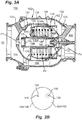
Figs. 3A and 3B are a cross-sectional view and schematic flow area view of the bleed valve ofFig. 1 , showing valve elements and selected flow area size relations, respectively; -
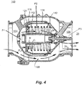
Fig. 4 is a cross-sectional view of the bleed valve ofFig. 1 , showing the piston disposed at an open position such that the duct fluidly coupled the inlet to the outlet of the bleed valve; -
Fig. 5 is a schematic view of the bleed valve ofFig. 1 , showing the piston disposed at an closed position such that the duct fluidly separates the inlet from the outlet of the bleed valve; -
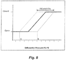
Figs. 6-8 are cross-sectional views and an adjustability plot of the bleed valve ofFig. 1 , showing a baffle disposed in first and second positions to provide adjustability of the differential pressure at which the bleed valve piston moves between the open and closed positions; and -
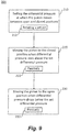
Fig. 9 is a method of setting differential pressure at which a bleed valve opens, showing steps of the method. - Reference will now be made to the drawings wherein like reference numerals identify similar structural features or aspects of the subject disclosure. For purposes of explanation and illustration, and not limitation, a partial view of an exemplary embodiment of a bleed valve in accordance with the disclosure is shown in
Fig. 1 and is designated generally byreference character 100. Other embodiments of bleed valves, compressors, gas turbine engines, and methods a controlling fluid flow through bleed valves in accordance with the disclosure, or aspects thereof, are provided inFigs. 2-9 , as will be described. The systems and methods described herein can be used for passively controlling inline bleed valves in gas turbine engines, though the present disclosure is not limited to gas turbine engines in general. - Referring to
Fig. 1 , agas turbine engine 10 is shown.Gas turbine engine 10 includescase 12 containing acompressor section 14, acombustion section 16, and aturbine section 18.Compressor section 14 is disposed in fluid communication withexternal environment 20 and is arranged to compress fluid 22 ingested fromexternal environment 20. Once compressedfluid 22 is communicated tocombustion section 16 as acompressed fluid 24. -
Combustion section 16 is disposed in fluid communication withcompressor section 14, is arranged to receive therefrom compressedfluid 24, and generates highpressure combustion products 26 usingcompressed fluid 24 and fuel also provided tocombustion section 16. Highpressure combustion products 26 are provided bycombustion section 16 toturbine section 18. -
Turbine section 18 is disposed in fluid communication withcombustion section 16 and is arranged to receive therefrom highpressure combustion products 26.Turbine section 18 expands highpressure combustion products 26 as highpressure combustion products 26traverse turbine section 18,turbine section 18 extractingwork 28 from highpressure combustion products 26 during expansion. A portion ofwork 28 is provided tocompressor section 14 to provide the input power necessary to compressfluid 22 for generatingcompressed fluid 24, the amount of work corresponding the amount of fluid and extent of compression required for the operating state ofgas turbine engine 10. Bleedvalve 100 is connected tocase 12 for reducing amount ofwork 28 provided tocompressor section 14 according to the operating regime ofgas turbine engine 10. - With reference to
Figs. 2 and3A ,compressor section 14 and bleedvalve 100 are shown. Bleedvalve 100 is fixed tocase 12 for selectively (shown with the dashed flow arrow inFig. 2 ) ventingcompressor section 14 toexternal environment 20.Compressor section 14 includes aplenum 30 which is in fluid communication with the gas path throughcompressor section 14 and is occupied bycompressed fluid 24. Aninlet 104 ofbleed valve 100 is in fluid communication withplenum 30 such that differential in pressure P1 at inlet 104 (shown inFig. 3A ) and pressure P3 at outlet 106 (shown inFig. 3A ) ofbleed valve 100. Differential between pressure P1 of compressedfluid 24 and P3 atoutlet 106, i.e., differential pressure P1-P3, is used to passively operatebleed valve 100. - Referring to
Fig. 3A , bleedvalve 100 includes ahousing 102 with aninlet 104 coupled to anoutlet 106 by aduct 108.Guide tube 110 with aguide tube orifice 134 is fixed inhousing 102 betweeninlet 104 andoutlet 106, apiston 112, andbaffle 162.Piston 112 has apiston orifice 114, is slideably supported onguide tube 110, and is movable between an open position 116 (shown inFig. 4 ) and a closed position 118 (shown inFig. 5 ).Duct 108 fluidly couplesinlet 104 withoutlet 106 inopen position 116.Duct 108 fluidly separatesinlet 104 fromoutlet 106 inclosed position 118.Guide tube orifice 134 andpiston orifice 114fluidly couple inlet 104 andoutlet 106 in bothopen position 116 andclosed position 118 to movepiston 112 betweenopen position 116 andclosed position 118 according to differential pressure P1-P3 betweenbleed valve inlet 104 andoutlet 106.Baffle 162 is slideably supported byguide tube 110 to set the differential pressure P1-P3 at whichpiston 112 moves betweenopen position 116 andclosed position 118.Outlet 106 can go to either the ambient environment or to a low pressure bypass flow stream, as suitable for an intended application. -
Housing 102 has aninlet portion 120 and anoutlet portion 122.Inlet portion 120 definesinlet 104, is sealably connected tooutlet portion 122 on an end opposite ofinlet portion 120 opposite (relative to a direction of flow through bleed valve 100)inlet 104, and has anopen seat 124 arranged within an interior ofinlet portion 120.Open seat 124 is configured to receivepiston 112 whenpiston 112 is in open position 116 (shown inFig. 4 ).Outlet portion 122 definesoutlet 106 and fastens toinlet portion 120 on an end ofoutlet portion 122 opposite (relative to a direction of flow through bleed valve 100)inlet 104. Aclosed seat 126 is arranged with an interior ofoutlet portion 122 to receive andsealably seat piston 112 whenpiston 112 is inclosed position 118. Connection ofinlet portion 120 tooutlet portion 122 can be with threaded fasteners or any other type of suitable fixation. -
Guide tube 110 extends axially betweeninlet 104 andoutlet 106 and has aninlet end 130, anoutlet end 132, and aguide tube orifice 134.Outlet end 132 is seated inoutlet portion 122 ofhousing 102.Guide tube orifice 134 is defined withinguide tube 110 at a location betweenoutlet end 132 andinlet end 130 and extends through a thickness of the wall definingguide tube 110.Inlet end 130 opposesinlet 104 on a side ofguide tube orifice 134opposite outlet end 132. Anend cap 150 is seated onguide tube 110 facinginlet 104 separating an interior 164 ofguide tube 110 frominlet 104. As shown inFig. 3A guide tube orifice 134 is one of plurality ofguide tube orifices 134 defined between inner and outer surfaces ofguide tube 110. -
Piston 112 is slidably seated onguide tube 110 and has aface 136 and askirt 138. Face 136 opposesinlet 104.Skirt 138 extends fromface 136 towardsoutlet 106 and has aninner portion 140 and anouter portion 142.Inner portion 140 extends aboutguide tube 110 and is in sliding engagement with an outer surface ofguide tube 110.Outer portion 142 extends aboutinner portion 140 is sealably received betweeninlet portion 120 andoutlet portion 122 ofhousing 102.Piston orifice 114 extends throughpiston face 136 tofluidly couple inlet 104 with a volume bounded by the downstream surface offace 136 and opposing faces ofinner portion 140 andouter portion 142 ofskirt 138. Aninner sealing member 144 is seated withinouter portion 122 ofhousing 102, extends aboutguide tube 110, and abuts an inner surface ofouter portion 142 to prevent fluid flow therebetween. An outer sealingmember 146 is seated withininlet portion 120 ofhousing 102, extends about skirtouter portion 142, and abuts an outer surface of skirtouter portion 142 to prevent fluid flow therebetween.Skirt 138 is slideably received between inner sealingmember 144 and outer sealingmember 146 to sealably move between open position 116 (shown inFig. 4 ) and closed position 118 (shown inFig. 5 ). - A biasing
member 148 is arranged betweenpiston 112 andhousing 102.Biasing member 148 is arranged to exert a biasing force B (shown inFig. 4 ) onpiston 112, biasing forceB urging piston 112 in the direction ofinlet 104 and towardopen seat 124. It is contemplated that biasing force B cooperate with pressure P2 to exert a chamber pressure force C (shown inFig. 4 ) onpiston 112. Biasing force B and chamber pressure force C cooperate to oppose a plenum fluid force P (shown inFig. 4 ) exerted onpiston 112 by compressed fluid 24 (shown inFig. 1 ), plenum fluid force P always being equivalent to or greater than chamber pressure force C. Location ofpiston 112 withinhousing 102, e.g., open position 116 (shown inFig. 4 ) and closed position 118 (shown inFig. 5 ), is governed by equilibrium between biasing force B, chamber force C, and plenum fluid force P. As shown inFig. 3A biasing member 148 includes a spring element arranged between an inner surface ofpiston face 136 andoutlet portion 122 ofhousing 102. As will be appreciated by those of skill in the art in view of the present disclosure, other spring element arrangements and/or types of biasing elements can be used and remain within the scope of the present disclosure, as suitable for an intended application. - Referring to
Fig. 4 ,piston 112 is shown subsequent to movement to openposition 116. Inopen position 116piston 112 abutsopen seat 124. Movement ofpiston 112 againstopen seat 124 such thatpiston 112 abutsopen seat 124 withdrawsskirt 138, and more particularlyouter portion 142 ofskirt 138, fromduct 108. Withdrawal ofskirt 138 causesduct 108 tofluidly couple inlet 104 withoutlet 106,compressed fluid 24 thereby flowing throughduct 108 such that pressurized fluid flows throughbleed valve 100, ventingplenum 30 to theexternal environment 20 or a low pressure bypass duct.Piston 112 remains in abutment withopen seat 124 while differential pressure P1-P3 remains below the predetermined value. When differential pressure P1-P3 acrossbleed valve 100 exceeds the predetermined differentialpressure valve piston 112 moves to closed position 118 (shown inFig. 5 ). - Referring to
Fig. 5 ,piston 112 is shown subsequent to movement toclosed position 118. Inclosed position 118 piston abuts closedseat 126. Movement ofpiston 112 such thatpiston 112 abuts closedseat 126 introducesskirt 138, and more particularly skirtouter portion 14, intoduct 108. Insertion ofskirt 138 intoduct 108 in turn causesduct 108 to fluidlyseparate inlet 104 fromoutlet 106, substantially nocompressed fluid 24 thereby passing betweeninlet 104 andoutlet 106 throughduct 108. It is contemplated thatpiston 112 remain in abutment withclosed seat 126 while the differential pressure P1-P3 acrossbleed valve 100 remains above the predetermined value. In certain embodiments the predetermined value demarcates a transition between starting and steady-state operation of a compressor, e.g., compressor section 14 (shown inFig. 1 ) of gas turbine engine 10 (shown inFig. 1 ). - With continuing reference to
Fig. 3A , when the pressure differential P1-P3 drops below a predetermined value, apiston 112 moves to an open position 116 (shown inFig. 4 ). Movement ofpiston 112 to open position allows compressedfluid 24 to flow fromplenum 30 toexternal environment 20 through aduct 108 withinbleed valve 100. When the pressure differential P1-P3 rises above the predetermined value apiston 112 moves to a closed position 118 (shown inFig. 5 ). Movement ofpiston 112 to closed position causespiston 112 to blockduct 108 such thatduct 108 fluidly separatesoutlet 106 frominlet 104. - In both closed position 118 (shown in
Fig. 5 ) and open position 116 (shown inFig. 4 ), as well as positions intermediateopen position 116 andclosed position 118,outlet 106 andinlet 104 are in fluid communication with one another throughpiston orifice 114 and guidetube orifice 134. Fluid communication throughpiston orifice 114 and guidetube orifice 134 causes compressedfluid 24 to flow throughbleed valve 100 in bothopen position 116 andclosed position 118, as shown with flow arrows passing throughpiston orifice 114 and guidetube orifice 134 inFigs. 4 and5 . The flow causes chamber pressure P2 withinpiston 112 to vary according to pressure differential P1-P3, applicants appreciating that the benefit of a limited flow of compressedfluid 24 throughbleed valve 100 while closed provides for passive operation outweighs the loss of compressedfluid 24 flowing throughbleed valve 100 whilebleed valve 100 is inclosed position 118. This is because, as shown inFig. 3B , the minimum flow areas (156/158) defined bypiston orifice 114 and guidetube orifice 134 are relatively small in comparison to flow areas 154/152 ofinlet 104 andoutlet 106. - Referring to
Figs. 3B andFig. 8 , the differential pressure P1-P3 at whichpiston 112 moves betweenopen position 116 andclosed position 118 is determined by the minimum flow area within anorifice network 114/116 includingpiston orifice 114 and guidetube orifice 134. In embodiments described herein flowarea 158 ofguide tube orifice 134 defines the minimum flow area withinorifice network 114/116.Flow area 158 is in turn defined by the position ofbaffle 162 relativeguide tube orifice 134, thereby providing adjustability according to flow area ofguide tube orifice 134. This is illustrated schematically inFig. 3B with the differential in relative size offlow area 158 within the dotted outline and dashed outline, which correspond to the adjustability range between open differential pressure thresholds A and B inFig. 8 . Although described as being a singular set differential pressure herein, it is to be understood and appreciated that the set differential pressure can include both an open differential pressure and a close differential pressure, as shown with the slope of the differential function shown inFig. 8 . - With reference to
Figs. 6 and7 , aset mechanism 164 for controlling position ofbaffle 162 relative to guidetube orifice 134 is shown.Baffle 162 has aface portion 166 with aset pin aperture 169 and askirt portion 171, is slideably supported byguide tube 110, and is operably associated withset mechanism 164 to set the differential pressure P1-P3 at whichpiston 112 moves between open position 116 (shown inFig. 4 ) and closed position 118 (shown inFig. 5 ). In thisrespect baffle 162 extends circumferentially about an interior surface ofguide tube 110 and has a first position 168 (shown inFig. 6 ) and a second position 170 (shown inFig. 7 ).Skirt portion 171 radially bounds guidetube orifices 134, which each extend axially along a portion of the length ofguide tube 110, in either (or both)first position 168 andsecond position 170. - Flow area 158 (shown in
Fig. 3B ) ofguide tube orifice 134 is larger in second position 170 (shown with the dashed outline boundingflow area 158 inFig. 3B ) than in first position 168 (shown with the dotted outline boundingflow area 158 inFig. 3B ). Whenbaffle 162 is infirst position 168piston 112 moves between open position 116 (shown inFig. 4 ) to closed position 118 (shown inFig. 5 ) at differential pressure A (shown inFig. 8 ). Whenbaffle 162 is insecond position 170piston 112 moves betweenopen position 116 andclosed position 118 at differential pressure B. Operable connection ofset mechanism 164 withbaffle 162 allows for selection of differential pressure at which bleedvalve 100 opens. This allows bleedvalve 100 to be used on engines requiring actuation at different pressure differentials. It is contemplated that adjustability ofbaffle 112 be continuous, meaning that position ofbaffle 162 can be selectedsuch bleed valve 100 moves betweenopen position 116 andclosed position 118 at any differential pressure between differential pressure A and differential B. - In the illustrated exemplary embodiment set
mechanism 164 includes aset pin 172 with aflange 174, acollar 176, and asleeve 178. Setpin 172 movably couples baffle to the housing for displacement of the baffle relative to the guide tube.Flange 174 extends about setpin 172adjacent baffle 162 and fixes baffle 162 to setpin 172.Collar 176 threadably seats about an end ofset pin 172 and fixes baffle 162 to setpin 172. Setpin 172 is in turn received within aset pin aperture 181 defined withinhousing 102, setpin 172 arranged betweenguide tube orifice 134 andhousing aperture 182 fluidly couplingguide tube orifice 134 withoutlet 106, and setpin 172 being free for rotation and axial movement (both shown with arrows inFig. 7 ) withinsleeve 178 and relative tohousing 102 for setting differential pressure P1-P3. As will be appreciated by those of skill in the art in view of the present disclosure, this provide adjustability to bleedvalve 100 by allowing differential pressure P1-P3 to be adjusted for needs of the particulate type (or serial number) of gas turbine engine. Physical adjustment can be accomplished, for example, via atool engagement feature 180 arranged on an end ofset pin 172opposite baffle 162. - Referring now to
Fig. 9 ,method 200 of controlling fluid flow through a bleed valve, e.g., bleed valve 100 (shown inFig. 1 ), is shown.Method 200 includes setting the differential pressure between the inlet and the outlet of the bleed valve at which the piston moves between an open position and a closed position, e.g., differential pressure P-P3 (shown inFig. 4 ), as shown withbox 210. When the differential pressure rises above below the set differential pressure a piston of the bleed valve, e.g., piston 112 (shown inFig. 3A ), moves to the closed position, e.g., closed position 118 (shown inFig. 5 ), as shown withbox 220. This causes bleed valve duct 108 (shown inFig. 3A ) to fluidly separate inlet 104 (shown inFig. 3A ) from outlet 106 (shown inFig. 3B ). When the differential pressure drops below the set differential pressure the piston moves to the open position such that the duct fluidly couples the inlet to the outlet, as shown withbox 230. - It is contemplated that movement between the open position and the closed position can be passive, i.e., without the employment of a solenoid or muscle force from a pressurized fluid source, as shown
box Fig. 7 ) connecting the baffle to the bleed valve housing, thereby changing flow area of the orifice, as shown withbox 212. - Inline bleed valves for gas turbine engines are generally operated by a pneumatic controller. The pneumatic controller controls so-called muscle pressure to the inline bleed valve, applying the muscle pressure into a actuation chamber to actuate the inline bleed valve. While generally acceptable for their intended function such pneumatic controllers and actuation chambers can add complexity, mass, and/or size to the inline bleed valve.
- In certain embodiments described herein passive inline bleed valves function solely according to the pressure at bleed valve inlet and outlet. In this respect the bleed valve can include an orifice network with orifices defined within the inline bleed valve and fluidly between the inlet and the outlet. By selecting suitable sizing of the orifice flow area internal leakage through the inline bleed valve and pressure within chambers defined within the inline bleed valve interior can be controlled, pressure within a chamber located fluidly downstream of the bleed valve piston balancing force on the piston from pressure within a chamber located fluidly upstream of the bleed valve piston. The net force on the piston is a function of the pressures on each side of the piston and pressure exerted on the piston by the biasing member, the amount of force exerted on the piston thus controlling valve actuation pressure.
- The methods and systems of the present disclosure, as described above and shown in the drawings, provide for inline bleed valves with superior properties including passive control. Being passively controlled the inline bleed valves do not require an active control mechanism, such as a solenoid and/or a controller. This can reduce complexity, mass, and size of the bleed valve, potentially improving reliability and/or reducing cost. While the apparatus and methods of the subject disclosure have been shown and described with reference to preferred embodiments, those skilled in the art will readily appreciate that changes and/or modifications may be made thereto without departing from the scope of the subject disclosure.
Claims (15)
- A bleed valve (100), comprising:a housing (102) with an inlet (104) coupled to an outlet (106) by a duct (108);a guide tube (110) with an orifice (134) fixed in the housing (102) between the inlet (104) and the outlet (106);a piston (112) slideably supported on the guide tube (110) and movable between an open position (116) and a closed position (118), the duct (108) fluidly coupling the inlet (104) to the outlet (106) in the open position (116), the duct (108) fluidly separating the inlet (104) from the outlet (106) in the closed position (118),wherein the orifice (134) fluidly couples the inlet (104) with the outlet (106) in the open position (116) and the closed position (118) to move piston (112) between the open position (116) and the closed position (118) according to differential pressure between the inlet (104) and the outlet (106) of the bleed valve (100); anda baffle (162) slideably supported by the guide tube (110) to set the differential pressure at which the piston (112) moves between the open position (116) and the closed position (118).
- The bleed valve as recited in claim 1, wherein the baffle (162) has a first position and a second position, flow area through the orifice (134) is larger in the second position than in the first position, the baffle (162) movable continuously between the first position and the second position to set a flow area through the orifice (134).
- The bleed valve as recited in claims 1 or 2, wherein the baffle (162) has skirt portion overlapping a portion of the orifice (134) in at least one of the first position and the second position; and/or wherein the baffle (162) has a face portion with a set pin aperture (181), the face portion arranged within an interior of the guide post.
- The bleed valve as recited in any preceding claim, further comprising a set pin (172) movably coupling the baffle (162) to the housing (102) for displacement of the baffle (162) relative to the guide tube (110).
- The bleed valve as recited in claim 4, further comprising a collar (176) connected to the set pin (172) and fixing the baffle (162) to the set pin (172); and/or wherein the set pin (172) has a flange (174) arranged on the set pin (172) adjacent the baffle (162) and fixing the baffle (162) to the set pin (172).
- The bleed valve as recited in claims 4 or 5, wherein the housing (102) has a set pin aperture (181), the set pin (172) received within the set pin aperture (181), the set pin (172) free for rotation and axial movement relative to the housing (102) for setting the predetermined differential pressure, and preferably further comprising a sleeve (178) threadably seated in the set pin aperture (181), the set pin (172) received within the sleeve (178), and more preferably wherein the set pin (172) is threadably coupled to the sleeve (178) for rotation and displacement relative to sleeve (178) when moving between the first position and the second position.
- The bleed valve as recited in any of claims 4-6, wherein the set pin (172) has a tool engagement feature arranged on an end of the set pin (172) opposite the baffle (162).
- The bleed valve as recited in any preceding claim, wherein the baffle (162) extends circumferentially about an interior of the guide tube (110).
- The bleed valve as recited in any preceding claim, wherein the orifice (134) comprises a plurality of axially extending slots, the baffle (162) overlapping the plurality of axially extending slots in at least one of the first position and the second position.
- The bleed valve as recited in any preceding claim, wherein the housing (102) has a housing orifice defined in the housing (102) and fluidly coupling the guide tube orifice (134) with the bypass channel, the set pin (172) disposed between guide tube orifice (134) and the housing aperture.
- A gas turbine engine, comprising:a compressor with a plenum;a turbine operably connected to the compressor; anda bleed valve (100) as recited in claim 1 coupling the plenum with the external environment, wherein the bleed valve (100) comprises a set pin (172) movably coupling the baffle (162) to the housing (102) for displacement of the baffle (162) relative to the guide tube (110),wherein the set pin (172) is threadably coupled to the housing (102) for rotation and displacement relative to sleeve (172) to set the differential pressure.
- The gas turbine engine as recited in claim 11, wherein the housing (102) has a housing aperture fluidly coupling the guide tube orifice (134) with the bypass channel, the set pin (172) arranged between guide tube orifice (134) and the housing aperture.
- A method of setting differential pressure at which a bleed valve opens, comprising:at a bleed valve having a housing with an inlet coupled to an outlet by a duct, a guide tube with an orifice fixed in the housing between the inlet and the outlet, a piston slideably supported on the guide tube and movable between an open position and a closed position, and a baffle slideably supported by the guide tube to set a differential pressure at which the piston moves between the open position and the closed position;setting the differential pressure between the inlet and the outlet of the bleed valve at which the piston moves between an open position and a closed position;moving the piston to the closed position when the differential pressure rises above the differential pressure such that the duct fluidly separates the inlet from the outlet;moving the piston to the open position when the differential pressure drops below above the differential pressure such that the duct fluidly couples the inlet to the outlet.
- The method as recited in claim 13, wherein movement between the open position and the closed position is passive.
- The method as recited in claims 13 or 14, wherein setting the differential pressure comprises rotating a set pin connecting the baffle to the housing; and/or wherein setting the differential pressure comprises changing flow area of the orifice.
Applications Claiming Priority (1)
| Application Number | Priority Date | Filing Date | Title |
|---|---|---|---|
| US16/054,869 US10975875B2 (en) | 2018-08-03 | 2018-08-03 | Passive bleed valves with adjustable pressure threshold |
Publications (2)
| Publication Number | Publication Date |
|---|---|
| EP3604743A1 true EP3604743A1 (en) | 2020-02-05 |
| EP3604743B1 EP3604743B1 (en) | 2022-10-05 |
Family
ID=67658297
Family Applications (1)
| Application Number | Title | Priority Date | Filing Date |
|---|---|---|---|
| EP19189049.0A Active EP3604743B1 (en) | 2018-08-03 | 2019-07-30 | Passive bleed valves with adjustable pressure threshold |
Country Status (2)
| Country | Link |
|---|---|
| US (2) | US10975875B2 (en) |
| EP (1) | EP3604743B1 (en) |
Families Citing this family (2)
| Publication number | Priority date | Publication date | Assignee | Title |
|---|---|---|---|---|
| US11906071B1 (en) | 2022-08-26 | 2024-02-20 | Hamilton Sundstrand Corporation | Remote passively and actively actuated valve systems |
| US12313010B2 (en) * | 2023-04-04 | 2025-05-27 | Pratt & Whitney Canada Corp. | Systems and methods for adjusting a modulation characteristic of a bleed-off valve of a gas turbine engine |
Citations (3)
| Publication number | Priority date | Publication date | Assignee | Title |
|---|---|---|---|---|
| GB2376515A (en) * | 2001-06-13 | 2002-12-18 | Rolls Royce Plc | Bleed valve for the compressor of a gas turbine engine |
| EP3056739A1 (en) * | 2015-02-13 | 2016-08-17 | Hamilton Sundstrand Corporation | Sleeve type bleed valve actuated by two control pressures acting on a piston |
| EP3070336A1 (en) * | 2015-03-16 | 2016-09-21 | Hamilton Sundstrand Corporation | Self-actuated, in-line bleed valve |
Family Cites Families (20)
| Publication number | Priority date | Publication date | Assignee | Title |
|---|---|---|---|---|
| US1636662A (en) * | 1927-07-19 | Valve | ||
| US2265435A (en) * | 1938-02-11 | 1941-12-09 | Universal Hydraulic Corp | Tube valve |
| US2608204A (en) * | 1945-08-13 | 1952-08-26 | Stephen M Dunn | Valve |
| US2780779A (en) | 1952-12-05 | 1957-02-05 | Gen Electric | Electric current measuring apparatus |
| US2870779A (en) * | 1955-12-09 | 1959-01-27 | Cook Electric Co | Automatic check valve |
| US3493008A (en) * | 1966-10-10 | 1970-02-03 | Paul J Scaglione | Pressure balanced regulating valve |
| US4182117A (en) * | 1978-01-09 | 1980-01-08 | Avco Corporation | Diffuser vane cusp bleed aperture with automatic ejector control device |
| FR2723981B1 (en) | 1994-08-24 | 1996-09-20 | Snecma | SELF-REGULATED AIR TAKE-OFF DEVICE FOR A TURBOMACHINE |
| WO1996034194A2 (en) | 1995-04-27 | 1996-10-31 | Richard Nigel Bushell | Automatic valve for the inlet manifold of an internal combustion engine |
| RU2159377C1 (en) * | 1999-02-23 | 2000-11-20 | Открытое акционерное общество НПО Энергомаш им. акад. В.П. Глушко | Flowmeter |
| US6701715B2 (en) * | 2002-05-02 | 2004-03-09 | Honeywell International, Inc. | Variable geometry ejector for a bleed air system using integral ejector exit pressure feedback |
| WO2004094822A2 (en) | 2003-04-22 | 2004-11-04 | R. Conrader Company | Air compressor with inlet control mechanism and automatic inlet control mechanism |
| US7004186B2 (en) * | 2003-06-30 | 2006-02-28 | The Boeing Company | Surge relief apparatus for a valve |
| US7555905B2 (en) * | 2006-03-28 | 2009-07-07 | United Technologies Corporation | Self-actuating bleed valve for gas turbine engine |
| US7493912B2 (en) * | 2006-06-09 | 2009-02-24 | Hartman Brian T | Fixed cone sleeve valve having cone supported by means downstream of the gate in its closed position |
| US8814498B2 (en) | 2010-11-18 | 2014-08-26 | Hamilton Sundstrand Corporation | Self-actuating bleed valve for a gas turbine engine |
| US20170191373A1 (en) | 2015-12-30 | 2017-07-06 | General Electric Company | Passive flow modulation of cooling flow into a cavity |
| CA3018212C (en) * | 2016-03-23 | 2021-10-12 | Dukes Aerospace, Inc. | Inlet pressure compensation for a valve system |
| PT3449331T (en) * | 2016-04-26 | 2020-02-03 | Oxford Flow Ltd | Device for controlling fluid flow |
| US10513977B2 (en) * | 2018-03-06 | 2019-12-24 | Hamilton Sundstrand Corporation | Adjustable snap action passive inline air valve |
-
2018
- 2018-08-03 US US16/054,869 patent/US10975875B2/en active Active
-
2019
- 2019-07-30 EP EP19189049.0A patent/EP3604743B1/en active Active
-
2021
- 2021-03-05 US US17/193,235 patent/US11346356B2/en active Active
Patent Citations (3)
| Publication number | Priority date | Publication date | Assignee | Title |
|---|---|---|---|---|
| GB2376515A (en) * | 2001-06-13 | 2002-12-18 | Rolls Royce Plc | Bleed valve for the compressor of a gas turbine engine |
| EP3056739A1 (en) * | 2015-02-13 | 2016-08-17 | Hamilton Sundstrand Corporation | Sleeve type bleed valve actuated by two control pressures acting on a piston |
| EP3070336A1 (en) * | 2015-03-16 | 2016-09-21 | Hamilton Sundstrand Corporation | Self-actuated, in-line bleed valve |
Also Published As
| Publication number | Publication date |
|---|---|
| US11346356B2 (en) | 2022-05-31 |
| US20210348619A1 (en) | 2021-11-11 |
| US10975875B2 (en) | 2021-04-13 |
| US20200040901A1 (en) | 2020-02-06 |
| EP3604743B1 (en) | 2022-10-05 |
Similar Documents
| Publication | Publication Date | Title |
|---|---|---|
| US11674452B2 (en) | Passive active poppet-type bleed valves | |
| EP3056739B1 (en) | Sleeve type bleed valve actuated by two control pressures acting on a piston | |
| EP3246607B1 (en) | In-line shutoff valves | |
| US11346356B2 (en) | Passive bleed valves with adjustable pressure threshold | |
| US9080687B2 (en) | Pressure and flow altitude compensated shutoff valve | |
| EP3045699A1 (en) | Anti-icing systems | |
| US10865800B2 (en) | Bleed valve with regulated opening | |
| EP3775639B1 (en) | Damped check valve having multi-pressure operation | |
| EP3623583B1 (en) | System for adjusting a variable position vane in an aircraft engine | |
| EP3754232B1 (en) | Inline valve | |
| EP3604744B1 (en) | Passively controlled inline bleed valves | |
| EP3754230B1 (en) | Inline valves, gas turbine engines with inline bleed valves, and methods controlling flow through inline valves | |
| EP3572641B1 (en) | Bleed valves | |
| EP3754231B1 (en) | Pneumatic controllers, pneumatically controlled inline valves, and methods of cooling pneumatic controllers | |
| EP4485119B1 (en) | Pressure control valve |
Legal Events
| Date | Code | Title | Description |
|---|---|---|---|
| PUAI | Public reference made under article 153(3) epc to a published international application that has entered the european phase |
Free format text: ORIGINAL CODE: 0009012 |
|
| STAA | Information on the status of an ep patent application or granted ep patent |
Free format text: STATUS: THE APPLICATION HAS BEEN PUBLISHED |
|
| AK | Designated contracting states |
Kind code of ref document: A1 Designated state(s): AL AT BE BG CH CY CZ DE DK EE ES FI FR GB GR HR HU IE IS IT LI LT LU LV MC MK MT NL NO PL PT RO RS SE SI SK SM TR |
|
| AX | Request for extension of the european patent |
Extension state: BA ME |
|
| STAA | Information on the status of an ep patent application or granted ep patent |
Free format text: STATUS: REQUEST FOR EXAMINATION WAS MADE |
|
| 17P | Request for examination filed |
Effective date: 20200731 |
|
| RBV | Designated contracting states (corrected) |
Designated state(s): AL AT BE BG CH CY CZ DE DK EE ES FI FR GB GR HR HU IE IS IT LI LT LU LV MC MK MT NL NO PL PT RO RS SE SI SK SM TR |
|
| GRAP | Despatch of communication of intention to grant a patent |
Free format text: ORIGINAL CODE: EPIDOSNIGR1 |
|
| STAA | Information on the status of an ep patent application or granted ep patent |
Free format text: STATUS: GRANT OF PATENT IS INTENDED |
|
| INTG | Intention to grant announced |
Effective date: 20220422 |
|
| GRAS | Grant fee paid |
Free format text: ORIGINAL CODE: EPIDOSNIGR3 |
|
| GRAA | (expected) grant |
Free format text: ORIGINAL CODE: 0009210 |
|
| STAA | Information on the status of an ep patent application or granted ep patent |
Free format text: STATUS: THE PATENT HAS BEEN GRANTED |
|
| AK | Designated contracting states |
Kind code of ref document: B1 Designated state(s): AL AT BE BG CH CY CZ DE DK EE ES FI FR GB GR HR HU IE IS IT LI LT LU LV MC MK MT NL NO PL PT RO RS SE SI SK SM TR |
|
| REG | Reference to a national code |
Ref country code: GB Ref legal event code: FG4D |
|
| REG | Reference to a national code |
Ref country code: CH Ref legal event code: EP |
|
| REG | Reference to a national code |
Ref country code: AT Ref legal event code: REF Ref document number: 1522875 Country of ref document: AT Kind code of ref document: T Effective date: 20221015 |
|
| REG | Reference to a national code |
Ref country code: DE Ref legal event code: R096 Ref document number: 602019020208 Country of ref document: DE |
|
| REG | Reference to a national code |
Ref country code: IE Ref legal event code: FG4D |
|
| REG | Reference to a national code |
Ref country code: LT Ref legal event code: MG9D |
|
| REG | Reference to a national code |
Ref country code: NL Ref legal event code: MP Effective date: 20221005 |
|
| REG | Reference to a national code |
Ref country code: AT Ref legal event code: MK05 Ref document number: 1522875 Country of ref document: AT Kind code of ref document: T Effective date: 20221005 |
|
| PG25 | Lapsed in a contracting state [announced via postgrant information from national office to epo] |
Ref country code: NL Free format text: LAPSE BECAUSE OF FAILURE TO SUBMIT A TRANSLATION OF THE DESCRIPTION OR TO PAY THE FEE WITHIN THE PRESCRIBED TIME-LIMIT Effective date: 20221005 |
|
| PG25 | Lapsed in a contracting state [announced via postgrant information from national office to epo] |
Ref country code: SE Free format text: LAPSE BECAUSE OF FAILURE TO SUBMIT A TRANSLATION OF THE DESCRIPTION OR TO PAY THE FEE WITHIN THE PRESCRIBED TIME-LIMIT Effective date: 20221005 Ref country code: PT Free format text: LAPSE BECAUSE OF FAILURE TO SUBMIT A TRANSLATION OF THE DESCRIPTION OR TO PAY THE FEE WITHIN THE PRESCRIBED TIME-LIMIT Effective date: 20230206 Ref country code: NO Free format text: LAPSE BECAUSE OF FAILURE TO SUBMIT A TRANSLATION OF THE DESCRIPTION OR TO PAY THE FEE WITHIN THE PRESCRIBED TIME-LIMIT Effective date: 20230105 Ref country code: LT Free format text: LAPSE BECAUSE OF FAILURE TO SUBMIT A TRANSLATION OF THE DESCRIPTION OR TO PAY THE FEE WITHIN THE PRESCRIBED TIME-LIMIT Effective date: 20221005 Ref country code: FI Free format text: LAPSE BECAUSE OF FAILURE TO SUBMIT A TRANSLATION OF THE DESCRIPTION OR TO PAY THE FEE WITHIN THE PRESCRIBED TIME-LIMIT Effective date: 20221005 Ref country code: ES Free format text: LAPSE BECAUSE OF FAILURE TO SUBMIT A TRANSLATION OF THE DESCRIPTION OR TO PAY THE FEE WITHIN THE PRESCRIBED TIME-LIMIT Effective date: 20221005 Ref country code: AT Free format text: LAPSE BECAUSE OF FAILURE TO SUBMIT A TRANSLATION OF THE DESCRIPTION OR TO PAY THE FEE WITHIN THE PRESCRIBED TIME-LIMIT Effective date: 20221005 |
|
| PG25 | Lapsed in a contracting state [announced via postgrant information from national office to epo] |
Ref country code: RS Free format text: LAPSE BECAUSE OF FAILURE TO SUBMIT A TRANSLATION OF THE DESCRIPTION OR TO PAY THE FEE WITHIN THE PRESCRIBED TIME-LIMIT Effective date: 20221005 Ref country code: PL Free format text: LAPSE BECAUSE OF FAILURE TO SUBMIT A TRANSLATION OF THE DESCRIPTION OR TO PAY THE FEE WITHIN THE PRESCRIBED TIME-LIMIT Effective date: 20221005 Ref country code: LV Free format text: LAPSE BECAUSE OF FAILURE TO SUBMIT A TRANSLATION OF THE DESCRIPTION OR TO PAY THE FEE WITHIN THE PRESCRIBED TIME-LIMIT Effective date: 20221005 Ref country code: IS Free format text: LAPSE BECAUSE OF FAILURE TO SUBMIT A TRANSLATION OF THE DESCRIPTION OR TO PAY THE FEE WITHIN THE PRESCRIBED TIME-LIMIT Effective date: 20230205 Ref country code: HR Free format text: LAPSE BECAUSE OF FAILURE TO SUBMIT A TRANSLATION OF THE DESCRIPTION OR TO PAY THE FEE WITHIN THE PRESCRIBED TIME-LIMIT Effective date: 20221005 Ref country code: GR Free format text: LAPSE BECAUSE OF FAILURE TO SUBMIT A TRANSLATION OF THE DESCRIPTION OR TO PAY THE FEE WITHIN THE PRESCRIBED TIME-LIMIT Effective date: 20230106 |
|
| P01 | Opt-out of the competence of the unified patent court (upc) registered |
Effective date: 20230522 |
|
| REG | Reference to a national code |
Ref country code: DE Ref legal event code: R097 Ref document number: 602019020208 Country of ref document: DE |
|
| PG25 | Lapsed in a contracting state [announced via postgrant information from national office to epo] |
Ref country code: SM Free format text: LAPSE BECAUSE OF FAILURE TO SUBMIT A TRANSLATION OF THE DESCRIPTION OR TO PAY THE FEE WITHIN THE PRESCRIBED TIME-LIMIT Effective date: 20221005 Ref country code: RO Free format text: LAPSE BECAUSE OF FAILURE TO SUBMIT A TRANSLATION OF THE DESCRIPTION OR TO PAY THE FEE WITHIN THE PRESCRIBED TIME-LIMIT Effective date: 20221005 Ref country code: EE Free format text: LAPSE BECAUSE OF FAILURE TO SUBMIT A TRANSLATION OF THE DESCRIPTION OR TO PAY THE FEE WITHIN THE PRESCRIBED TIME-LIMIT Effective date: 20221005 Ref country code: DK Free format text: LAPSE BECAUSE OF FAILURE TO SUBMIT A TRANSLATION OF THE DESCRIPTION OR TO PAY THE FEE WITHIN THE PRESCRIBED TIME-LIMIT Effective date: 20221005 Ref country code: CZ Free format text: LAPSE BECAUSE OF FAILURE TO SUBMIT A TRANSLATION OF THE DESCRIPTION OR TO PAY THE FEE WITHIN THE PRESCRIBED TIME-LIMIT Effective date: 20221005 |
|
| PLBE | No opposition filed within time limit |
Free format text: ORIGINAL CODE: 0009261 |
|
| STAA | Information on the status of an ep patent application or granted ep patent |
Free format text: STATUS: NO OPPOSITION FILED WITHIN TIME LIMIT |
|
| PG25 | Lapsed in a contracting state [announced via postgrant information from national office to epo] |
Ref country code: SK Free format text: LAPSE BECAUSE OF FAILURE TO SUBMIT A TRANSLATION OF THE DESCRIPTION OR TO PAY THE FEE WITHIN THE PRESCRIBED TIME-LIMIT Effective date: 20221005 Ref country code: AL Free format text: LAPSE BECAUSE OF FAILURE TO SUBMIT A TRANSLATION OF THE DESCRIPTION OR TO PAY THE FEE WITHIN THE PRESCRIBED TIME-LIMIT Effective date: 20221005 |
|
| 26N | No opposition filed |
Effective date: 20230706 |
|
| PG25 | Lapsed in a contracting state [announced via postgrant information from national office to epo] |
Ref country code: SI Free format text: LAPSE BECAUSE OF FAILURE TO SUBMIT A TRANSLATION OF THE DESCRIPTION OR TO PAY THE FEE WITHIN THE PRESCRIBED TIME-LIMIT Effective date: 20221005 |
|
| PG25 | Lapsed in a contracting state [announced via postgrant information from national office to epo] |
Ref country code: MC Free format text: LAPSE BECAUSE OF FAILURE TO SUBMIT A TRANSLATION OF THE DESCRIPTION OR TO PAY THE FEE WITHIN THE PRESCRIBED TIME-LIMIT Effective date: 20221005 |
|
| PG25 | Lapsed in a contracting state [announced via postgrant information from national office to epo] |
Ref country code: MC Free format text: LAPSE BECAUSE OF FAILURE TO SUBMIT A TRANSLATION OF THE DESCRIPTION OR TO PAY THE FEE WITHIN THE PRESCRIBED TIME-LIMIT Effective date: 20221005 |
|
| REG | Reference to a national code |
Ref country code: CH Ref legal event code: PL |
|
| REG | Reference to a national code |
Ref country code: BE Ref legal event code: MM Effective date: 20230731 |
|
| PG25 | Lapsed in a contracting state [announced via postgrant information from national office to epo] |
Ref country code: LU Free format text: LAPSE BECAUSE OF NON-PAYMENT OF DUE FEES Effective date: 20230730 |
|
| PG25 | Lapsed in a contracting state [announced via postgrant information from national office to epo] |
Ref country code: LU Free format text: LAPSE BECAUSE OF NON-PAYMENT OF DUE FEES Effective date: 20230730 |
|
| REG | Reference to a national code |
Ref country code: IE Ref legal event code: MM4A |
|
| PG25 | Lapsed in a contracting state [announced via postgrant information from national office to epo] |
Ref country code: CH Free format text: LAPSE BECAUSE OF NON-PAYMENT OF DUE FEES Effective date: 20230731 |
|
| PG25 | Lapsed in a contracting state [announced via postgrant information from national office to epo] |
Ref country code: IT Free format text: LAPSE BECAUSE OF FAILURE TO SUBMIT A TRANSLATION OF THE DESCRIPTION OR TO PAY THE FEE WITHIN THE PRESCRIBED TIME-LIMIT Effective date: 20221005 Ref country code: BE Free format text: LAPSE BECAUSE OF NON-PAYMENT OF DUE FEES Effective date: 20230731 |
|
| PG25 | Lapsed in a contracting state [announced via postgrant information from national office to epo] |
Ref country code: IE Free format text: LAPSE BECAUSE OF NON-PAYMENT OF DUE FEES Effective date: 20230730 |
|
| PG25 | Lapsed in a contracting state [announced via postgrant information from national office to epo] |
Ref country code: IE Free format text: LAPSE BECAUSE OF NON-PAYMENT OF DUE FEES Effective date: 20230730 |
|
| PG25 | Lapsed in a contracting state [announced via postgrant information from national office to epo] |
Ref country code: BG Free format text: LAPSE BECAUSE OF FAILURE TO SUBMIT A TRANSLATION OF THE DESCRIPTION OR TO PAY THE FEE WITHIN THE PRESCRIBED TIME-LIMIT Effective date: 20221005 |
|
| PG25 | Lapsed in a contracting state [announced via postgrant information from national office to epo] |
Ref country code: BG Free format text: LAPSE BECAUSE OF FAILURE TO SUBMIT A TRANSLATION OF THE DESCRIPTION OR TO PAY THE FEE WITHIN THE PRESCRIBED TIME-LIMIT Effective date: 20221005 |
|
| PGFP | Annual fee paid to national office [announced via postgrant information from national office to epo] |
Ref country code: GB Payment date: 20250619 Year of fee payment: 7 |
|
| PGFP | Annual fee paid to national office [announced via postgrant information from national office to epo] |
Ref country code: FR Payment date: 20250620 Year of fee payment: 7 |
|
| PG25 | Lapsed in a contracting state [announced via postgrant information from national office to epo] |
Ref country code: CY Free format text: LAPSE BECAUSE OF FAILURE TO SUBMIT A TRANSLATION OF THE DESCRIPTION OR TO PAY THE FEE WITHIN THE PRESCRIBED TIME-LIMIT; INVALID AB INITIO Effective date: 20190730 |
|
| PG25 | Lapsed in a contracting state [announced via postgrant information from national office to epo] |
Ref country code: HU Free format text: LAPSE BECAUSE OF FAILURE TO SUBMIT A TRANSLATION OF THE DESCRIPTION OR TO PAY THE FEE WITHIN THE PRESCRIBED TIME-LIMIT; INVALID AB INITIO Effective date: 20190730 |
|
| PGFP | Annual fee paid to national office [announced via postgrant information from national office to epo] |
Ref country code: DE Payment date: 20250620 Year of fee payment: 7 |
|
| PG25 | Lapsed in a contracting state [announced via postgrant information from national office to epo] |
Ref country code: TR Free format text: LAPSE BECAUSE OF FAILURE TO SUBMIT A TRANSLATION OF THE DESCRIPTION OR TO PAY THE FEE WITHIN THE PRESCRIBED TIME-LIMIT Effective date: 20221005 |