EP3604636A1 - Fiber production method and carbon fiber production method - Google Patents
Fiber production method and carbon fiber production method Download PDFInfo
- Publication number
- EP3604636A1 EP3604636A1 EP18778353.5A EP18778353A EP3604636A1 EP 3604636 A1 EP3604636 A1 EP 3604636A1 EP 18778353 A EP18778353 A EP 18778353A EP 3604636 A1 EP3604636 A1 EP 3604636A1
- Authority
- EP
- European Patent Office
- Prior art keywords
- spinneret
- fiber
- producing
- gas
- air flow
- Prior art date
- Legal status (The legal status is an assumption and is not a legal conclusion. Google has not performed a legal analysis and makes no representation as to the accuracy of the status listed.)
- Granted
Links
Images
Classifications
-
- D—TEXTILES; PAPER
- D01—NATURAL OR MAN-MADE THREADS OR FIBRES; SPINNING
- D01D—MECHANICAL METHODS OR APPARATUS IN THE MANUFACTURE OF ARTIFICIAL FILAMENTS, THREADS, FIBRES, BRISTLES OR RIBBONS
- D01D5/00—Formation of filaments, threads, or the like
- D01D5/06—Wet spinning methods
-
- D—TEXTILES; PAPER
- D01—NATURAL OR MAN-MADE THREADS OR FIBRES; SPINNING
- D01F—CHEMICAL FEATURES IN THE MANUFACTURE OF ARTIFICIAL FILAMENTS, THREADS, FIBRES, BRISTLES OR RIBBONS; APPARATUS SPECIALLY ADAPTED FOR THE MANUFACTURE OF CARBON FILAMENTS
- D01F6/00—Monocomponent artificial filaments or the like of synthetic polymers; Manufacture thereof
- D01F6/02—Monocomponent artificial filaments or the like of synthetic polymers; Manufacture thereof from homopolymers obtained by reactions only involving carbon-to-carbon unsaturated bonds
- D01F6/18—Monocomponent artificial filaments or the like of synthetic polymers; Manufacture thereof from homopolymers obtained by reactions only involving carbon-to-carbon unsaturated bonds from polymers of unsaturated nitriles, e.g. polyacrylonitrile, polyvinylidene cyanide
-
- D—TEXTILES; PAPER
- D01—NATURAL OR MAN-MADE THREADS OR FIBRES; SPINNING
- D01F—CHEMICAL FEATURES IN THE MANUFACTURE OF ARTIFICIAL FILAMENTS, THREADS, FIBRES, BRISTLES OR RIBBONS; APPARATUS SPECIALLY ADAPTED FOR THE MANUFACTURE OF CARBON FILAMENTS
- D01F9/00—Artificial filaments or the like of other substances; Manufacture thereof; Apparatus specially adapted for the manufacture of carbon filaments
- D01F9/08—Artificial filaments or the like of other substances; Manufacture thereof; Apparatus specially adapted for the manufacture of carbon filaments of inorganic material
- D01F9/12—Carbon filaments; Apparatus specially adapted for the manufacture thereof
- D01F9/14—Carbon filaments; Apparatus specially adapted for the manufacture thereof by decomposition of organic filaments
- D01F9/20—Carbon filaments; Apparatus specially adapted for the manufacture thereof by decomposition of organic filaments from polyaddition, polycondensation or polymerisation products
-
- C—CHEMISTRY; METALLURGY
- C01—INORGANIC CHEMISTRY
- C01B—NON-METALLIC ELEMENTS; COMPOUNDS THEREOF; METALLOIDS OR COMPOUNDS THEREOF NOT COVERED BY SUBCLASS C01C
- C01B32/00—Carbon; Compounds thereof
-
- C—CHEMISTRY; METALLURGY
- C01—INORGANIC CHEMISTRY
- C01B—NON-METALLIC ELEMENTS; COMPOUNDS THEREOF; METALLOIDS OR COMPOUNDS THEREOF NOT COVERED BY SUBCLASS C01C
- C01B32/00—Carbon; Compounds thereof
- C01B32/05—Preparation or purification of carbon not covered by groups C01B32/15, C01B32/20, C01B32/25, C01B32/30
-
- D—TEXTILES; PAPER
- D01—NATURAL OR MAN-MADE THREADS OR FIBRES; SPINNING
- D01F—CHEMICAL FEATURES IN THE MANUFACTURE OF ARTIFICIAL FILAMENTS, THREADS, FIBRES, BRISTLES OR RIBBONS; APPARATUS SPECIALLY ADAPTED FOR THE MANUFACTURE OF CARBON FILAMENTS
- D01F6/00—Monocomponent artificial filaments or the like of synthetic polymers; Manufacture thereof
- D01F6/28—Monocomponent artificial filaments or the like of synthetic polymers; Manufacture thereof from copolymers obtained by reactions only involving carbon-to-carbon unsaturated bonds
- D01F6/38—Monocomponent artificial filaments or the like of synthetic polymers; Manufacture thereof from copolymers obtained by reactions only involving carbon-to-carbon unsaturated bonds comprising unsaturated nitriles as the major constituent
-
- D—TEXTILES; PAPER
- D10—INDEXING SCHEME ASSOCIATED WITH SUBLASSES OF SECTION D, RELATING TO TEXTILES
- D10B—INDEXING SCHEME ASSOCIATED WITH SUBLASSES OF SECTION D, RELATING TO TEXTILES
- D10B2321/00—Fibres made from polymers obtained by reactions only involving carbon-to-carbon unsaturated bonds
- D10B2321/10—Fibres made from polymers obtained by reactions only involving carbon-to-carbon unsaturated bonds polymers of unsaturated nitriles, e.g. polyacrylonitrile, polyvinylidene cyanide
Definitions
- the present invention relates to a method of producing a fiber, which method enables production of a fiber by the dry-jet wet spinning method without causing dew condensation or generation of water droplets on the spinneret surface, and with remarkable stability of running of fibers.
- the dry-jet wet spinning method is a method in which a spinning dope solution containing a fiber-forming polymer dissolved in a solvent is extruded from a spinneret, and then once allowed to run in air, immediately followed by being guided into a coagulation bath liquid to allow coagulation.
- this method has less draft restriction in a gas, where the bath-liquid resistance is absent. Therefore, high-speed or high-draft spinning is possible, and the method is used for production of fibers for clothing and industrial uses.
- the dry-jet wet spinning method enables higher densification of fibers
- the method has recently been utilized for production of precursor fibers for high strength/high modulus carbon fibers, and the productivity in the dry-jet wet spinning method has been enhanced by performing high-speed spinning or increasing the holes in the spinneret.
- the droplets generated by the dew condensation cause clogging of the extrusion hole of the spinneret, fiber adhesion, uneven fineness, and single-fiber break, and further, spinneret immersion due to contact of the droplets with the coagulation liquid surface, leading to winding on rollers in the subsequent process and fuzzing or yarn break in the stretching process.
- the operability and the appearance are significantly deteriorated.
- Such problems become more serious especially when high-speed spinning is carried out, or when the number of holes in the spinneret is increased, in order to increase the productivity.
- Patent Document 1 a method for preventing dew condensation in dry-jet wet spinning, wherein a gas is allowed to flow, from one direction, in the gas-phase portion of the spinneret surface and the coagulation bath.
- Patent Document 2 a method for preventing accumulation of the solvent vapor, wherein the gas in the gas-phase portion formed between the extrusion surface of the spinneret and the coagulation bath is sucked alternately from two directions sandwiching the extrusion surface, has been studied (Patent Document 2).
- Patent Document 3 a method for controlling the temperature and the humidity in the vicinity of the spinneret to suppress dew condensation on the spinneret surface, wherein the inside of the coagulation chamber is surrounded, and wherein air with a controlled temperature and humidity is circulated therein, has also been studied (Patent Document 3).
- the technique proposed in Patent Document 1 may be able to effectively suppress dew condensation in some cases.
- the number of holes is not less than 2000, where the hole density is increased, or where the gas-phase portion in dry-jet wet spinning has a height of less than 20 mm in the vertically downward direction from the extrusion surface of the spinneret to the coagulation bath liquid surface, that is, under conditions where the solvent vapor easily accumulates in the gas-phase portion, deflection of the air flow occurs even by application of the technique proposed in Patent Document 1, causing accumulation of the vapor in some cases. This has been problematic since the dew condensation cannot be prevented.
- Patent Document 2 there are problems in that, when the hole density is high, insufficiency of suction in the gas-phase portion causes aggregation of the solvent vapor, and that the aggregation proceeds on surfaces not subjected to the exhaustion, causing dew condensation.
- An object of the present invention is to provide a method of producing a fiber, which method suppresses occurrence of dew condensation on the spinneret, and reduces deterioration of the appearance caused by winding on rollers in the subsequent process or by fuzzing or yarn break in the stretching process, to enable significant improvement of the productivity and the appearance as a whole even under conditions where, for example, not less than 2000 holes are present and the hole density is high, or where the gas-phase portion formed in the vertically downward direction from the extrusion surface of the spinneret to the coagulation bath liquid surface in dry-jet wet spinning has a height of less than 20 mm.
- the method of producing a fiber of the present invention has the following constitution. That is, the method is a method of producing a fiber, comprising extruding, from a spinneret, a spinning dope solution containing a fiber-forming polymer dissolved in a solvent, once allowing the solution to run in air, and then guiding the solution into a coagulation bath liquid to allow coagulation, wherein a gas-phase portion formed in a vertically downward direction from an extrusion surface of the spinneret to a coagulation bath liquid surface has a unidirectional air flow, and has an air flow rate per unit time (Af) which satisfies, in relation to the amount of the solvent in the spinning dope solution per unit time (As) in the gas-phase-portion volume (Vh), the relational expression 0.0008 m 3 ⁇ Af/(As/Vh) ⁇ 0.0015 m 3 .
- the relative standard deviation of the wind velocities at four points in the outer periphery of the spinneret in the gas-phase portion is preferably not more than 40%.
- the hourly average of the absolute humidity at each of four points in the outer periphery of the spinneret in the gas-phase portion is preferably not more than 20 g/m 3 .
- the number of holes in the spinneret is preferably not less than 2000 and not more than 50,000.
- the fiber-forming polymer is preferably an acrylonitrile copolymer.
- the method of producing a carbon fiber of the present invention has the following constitution. That is, the method is a method of producing a carbon fiber, comprising producing a fiber using an acrylonitrile copolymer as a fiber-forming polymer by the above method of producing a fiber, performing stabilization treatment in an oxidizing gas at 200 to 300°C, and then heating the fiber in an inert gas at not less than 1000°C.
- occurrence of dew condensation on a spinneret can be suppressed, and deterioration of the appearance caused by winding on rollers in the subsequent process or by fuzzing or yarn break in the stretching process can be reduced, thereby enabling significant improvement of the productivity and the appearance as a whole even under conditions of dry-jet wet spinning where, for example, not less than 2000 holes are present and the hole density is high, or where the distance between the spinneret and the coagulation bath liquid is less than 20 mm.
- the present invention is especially suitable for production of acrylonitrile precursor fibers for carbon fibers.
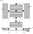
- Fig. 1 shows schematic top and front views of a spinning region in a case where an air supply nozzle and an exhaust nozzle are arranged in the present invention.
- the method of the present invention can be used for production of acrylonitrile fibers for clothing, acrylonitrile fibers for production of carbon fibers, aromatic polyamide fibers, and the like.
- the method shows the most remarkable effect in cases of production of acrylonitrile fibers for production of carbon fibers.
- a spinning dope solution containing a fiber-forming polymer dissolved in a solvent is used.
- the fiber-forming polymer examples include acrylonitrile copolymers and aromatic polyamides.
- a polymerization method for obtaining the polymer solution polymerization, emulsion/suspension polymerization, bulk polymerization, or the like is used. Either a batch method or a continuous method may be used.
- examples of the solvent in which the polymer is dissolved include dimethylsulfoxide (DMSO), dimethylformamide (DMF), dimethylacetamide (DMAc), aqueous zinc chloride solutions (ZnCl 2 aq), and aqueous sodium thiocyanate solutions (NaSCN aq).
- DMSO dimethylsulfoxide
- DMF dimethylformamide
- DMAc dimethylacetamide
- ZnCl 2 aq aqueous zinc chloride solutions
- NaSCN aq aqueous sodium thiocyanate solutions
- the spinning dope solution is extruded from an extrusion surface of a spinneret arranged above a coagulation bath through a gas-phase portion, and then the solution is allowed to coagulate in a coagulation bath, to form a fiber.
- the temperature of the spinning dope solution and the temperature of the coagulation bath their conditions are preferably set such that the difference between the atmospheric temperature and the dew point (atmospheric temperature - dew point) of the gas-phase portion formed in the vertically downward direction from the extrusion surface of the spinneret to the coagulation bath liquid surface is as large as possible.
- the temperature of the spinning dope solution a low temperature is preferred from the viewpoint of reducing the amount of evaporation of the solvent as long as the temperature is not less than the freezing point of the solvent used for the spinning dope solution.
- the temperature is preferably not more than the freezing point +20°C, further, not less than the freezing point +5°C, and not more than the freezing point +15°C.
- the spinning dope solution can have an appropriate viscosity, so that a favorable spinnability and an excellent operability can be achieved.
- the coagulation bath an aqueous solution of the same solvent as the solvent used for the spinning dope solution is usually used.
- the effect of the present invention remarkably appears especially in cases where an aqueous solution of DMSO, DMF, or DMAc is used as the coagulation bath.
- the temperature of the coagulation bath is preferably not more than 20°C, more preferably not more than 10°C, still more preferably not more than 7°C.
- the temperature of the coagulation bath is preferably not less than 0°C, more preferably not less than 1°C. In cases where the temperature of the coagulation bath is within this preferred temperature range, a favorable spinnability and an excellent operability can be achieved.
- the number of holes in the spinneret is preferably 2000 to 50,000, more preferably 4000 to 20,000. In cases where the number of holes is within this preferred range, a high productivity can be achieved. Moreover, since the mass of the spinneret does not increase excessively, workability can be secured, and the equipment cost can be suppressed. In cases where, for example, the spinneret area occupied by each hole (spinneret area ⁇ number of holes) is 5 mm 2 to 10 mm 2 , the effect of the present invention can be more easily produced.
- the present invention it is important to provide a unidirectional air flow in the gas-phase portion formed between the extrusion surface of the spinneret and the coagulation bath liquid surface, and to perform blowing at an air flow rate per unit time (Af) of 0.0008 m 3 to 0.0015 m 3 with respect to the amount of the solvent in the extruded dope solution per unit time (As) in the gas-phase-portion volume (Vh).
- the relative standard deviation of the wind velocities at four points in the outer periphery of the spinneret is preferably not more than 40%
- the hourly average of the absolute humidity at each of four points in the outer periphery of the spinneret is preferably not more than 20 g/m 3 .
- Examples of methods therefor include a method in which an air conditioner capable of controlling the humidity of the supplied air is arranged at a position distant from the spinneret, and air is blown into the gas-phase portion at a certain air flow rate, and a method in which an air supply nozzle or an exhaust nozzle is arranged.
- Af/(As/Vh) is 0.0008 m 3 to 0.0015 m 3 , preferably 0.0009 m 3 to 0.0014 m 3 , more preferably 0.0010 m 3 to 0.0013 m 3 .
- the relative standard deviation of the wind velocities at the four points in the outer periphery of the spinneret is preferably not more than 40%, more preferably not more than 20%, still more preferably not more than 10%.
- the hourly average of the absolute humidity at each of the four points in the outer periphery of the spinneret is preferably not more than 20 g/m 3 , more preferably not more than 15 g/m 3 , still more preferably not more than 10 g/m 3 .
- the air flow rate per unit time (Af) is calculated from, among the wind velocities measured at the four measurement points in the outer periphery of the spinneret, the wind velocity at one point positioned in the upstream side of the air flow, and the cross-sectional area as determined by seeing the spinneret from the upstream side of the air flow.
- the gas-phase-portion volume (Vh) is calculated from the extrusion area calculated from the outermost extrusion holes of the spinneret, and the height of the gas-phase portion formed in the vertically downward direction from the extrusion surface to the coagulation bath liquid surface.
- the amount of the solvent in the extruded dope solution (As) is the amount of the solvent contained in the dope solution extruded from the spinneret per unit time.
- the wind velocities, the air flow directions, and the absolute humidities at the four points in the outer periphery of the spinneret are measured at positions arranged such that the outer periphery of the spinneret is equally divided into four portions, and such that each position is at the middle point of the height from the liquid surface to the spinneret surface, and 30 mm distant from the outermost extrusion holes of the spinneret, irrespective of the shape of the spinneret.
- the four points in the outer periphery of the spinneret in cases where the spinneret has a circular shape, arbitrary four points on the circumference may be selected such that the outer circumference is equally divided into four portions.
- the spinneret has a rectangular shape
- the four midpoints of the segments constituting the outer periphery may be selected.
- the wind velocity and the absolute humidity are measured using Climomaster MODEL 6501 (Kanomax Japan Inc.).
- the hourly average of the absolute humidity at each of four points in the outer periphery of the spinneret is obtained by measuring the wind velocity, the temperature, and the relative humidity as described above 12 times at 5-minute intervals, calculating the absolute humidities using the above calculation equation, and then calculating their average for each measurement point.
- a Smoke Tester Set No. 500 (Gastec Corporation) was used. The tips of smoke tubes were placed at the measurement points described above, and the flow of smoke was observed from directly above each measurement point. The direction in which the yarn is taken from the coagulation bath is used as a reference direction. In cases where the difference between the angle at the point with the largest clockwise angle of the air flow direction and the angle of the air flow direction at each of all three remaining points is not more than 30°, the air flow is judged as a unidirectional flow. In cases where at least one point shows a difference of more than 30°, the air flow is judged as a scattering flow.
- the direction of the nozzle is preferably set such that the nozzle outlet is arranged in the spinneret direction, and in parallel to the coagulation bath liquid surface as shown in Fig. 1 . More specifically, the nozzle is arranged such that it is inclined at an angle of preferably 60° to 100°, more preferably 90° from the vertically downward direction (defined as 0°) toward the spinneret direction.
- Fig. 1 shows a case where each nozzle is arranged at an angle of 90°.
- the nozzle In cases where the nozzle is arranged such that it is inclined at an angle (nozzle angle) of not more than 100°, vapor generated from the solvent can be efficiently scavenged, and adhesion of dewdrops on the spinneret surface can be suppressed.
- the nozzle In cases where the nozzle is inclined at not less than 60°, either the air supply nozzle or the exhaust nozzle is less likely to cause fluctuation of the coagulation bath liquid surface, so that spinneret immersion due to contact of the liquid surface with the spinneret is less likely to occur, and adhesion between single fibers and the like can be effectively prevented.
- the appearance of the fibers can be maintained, and an excellent process stability can be achieved.
- vapor generated from the solvent is sucked while it is in contact with the spinneret surface. Therefore, growth of dewdrops may be promoted and enhanced, leading to early deterioration of the productivity and the appearance in some cases.
- the present invention is especially effective for production of an acrylonitrile fiber, especially an acrylonitrile fiber as a carbon fiber precursor, using an acrylonitrile copolymer. Details of the conditions specific to such cases are described below in detail.
- the spinning dope solution used for the dry-jet wet spinning is preferably a solution containing: an acrylonitrile copolymer containing acrylonitrile at not less than 90% by mass and less than 100%; and a vinyl monomer copolymerizable therewith; dissolved in the solution.
- an acrylonitrile copolymer containing acrylonitrile at not less than 90% by mass and less than 100% and a vinyl monomer copolymerizable therewith; dissolved in the solution.
- the amount of the acrylonitrile used in the acrylonitrile copolymer is within the preferred range described above, carbon fibers obtained by carbonization of the resulting acrylonitrile fibers have high strength, and therefore carbon fibers having excellent mechanical properties can be easily produced.
- the content of the solvent does not become excessive, dew condensation is less likely to be caused in the gas-phase portion between the spinneret and the coagulation bath liquid in dry-jet wet spinning.
- the present invention can be preferably applied to cases where fiber bundles each having a filament number of usually within the range of 2000 to 50,000, and a single fiber fineness of usually within the range of 0.5 dtex to 3 dtex, are obtained.
- the fiber bundle after fiber formation in the coagulation bath may be stretched directly in a stretching bath, or stretching in a bath may be carried out after removal of the solvent by washing with water.
- an oil agent is applied, and drying with a hot roller or the like is carried out. Further, when necessary, this is followed by stretching such as steam stretching, to obtain a fiber bundle.
- the following is a description of a method of producing a carbon fiber from a fiber obtained by the method of producing a fiber wherein the fiber-forming polymer is an acrylonitrile copolymer.
- An acrylonitrile fiber produced by the method of producing an acrylonitrile fiber is subjected to stabilization treatment in an oxidizing gas such as air at 200 to 300°C.
- the processing temperature is preferably increased from a low temperature to a high temperature in a plurality of steps.
- the fiber is preferably stretched at a high stretch ratio as long as fuzzing does not occur.
- the resulting stabilized fiber is heated at not less than 1000°C in an inert gas such as nitrogen, to produce a carbon fiber.
- the present invention is described below more concretely by way of Examples.
- the wind velocities, the air flow directions, and the absolute humidities at the four points in the outer periphery of the spinneret used in the present Examples were measured at the four midpoints of the segments constituting the outer periphery of the spinneret having a rectangular shape, wherein each point was positioned at the middle point of the height from the liquid surface to the spinneret surface, and 30 mm distant from the outermost extrusion holes of the spinneret.
- the wind velocity, the temperature, and the relative humidity were measured using Climomaster MODEL 6501 (Kanomax Japan Inc.).
- the hourly average of the absolute humidity at each of the four points in the outer periphery of the spinneret was obtained by measuring the wind velocity, the temperature, and the relative humidity as described above 12 times at 5-minute intervals, calculating the absolute humidities using the above calculation equation, and then calculating their average for each measurement point.
- a Smoke Tester Set No. 500 (Gastec Corporation) was used. The tips of smoke tubes were placed at the measurement points described above, and the flow of smoke was observed from directly above each measurement point. The direction in which the yarn was taken from the coagulation bath was used as a reference direction. In cases where the difference between the angle at the point with the largest clockwise angle of the air flow direction and the angle of the air flow direction at each of all three remaining points was not more than 30°, the air flow was judged as a unidirectional flow. In cases where at least one point showed a difference of more than 30°, the air flow was judged as a scattering flow.
- the air flow rate per unit time (Af) was calculated from, among the wind velocities measured at the four measurement points, the wind velocity at one point positioned in the upstream side of the air flow, and the cross-sectional area as determined by seeing the spinneret from the upstream side of the air flow.
- the gas-phase-portion volume (Vh) was calculated from the extrusion area calculated from the outermost extrusion holes of the spinneret, and the height of the gas-phase portion formed in the vertically downward direction from the extrusion surface to the coagulation bath liquid surface.
- the amount of the solvent in the extruded dope solution (As) is the amount of the solvent contained in the dope solution extruded from the spinneret per unit time.
- the sizes and the number of dewdrops on the spinneret surface were measured after one week of continuous spinning, and scored according to the following standard.
- Dewdrop diameter less than 2 mm: 1 point/dewdrop Dewdrop diameter, not less than 2 mm and less than 5 mm: 5 points/dewdrop Dewdrop diameter, not less than 5 mm: 10 points/dewdrop
- the fuzz number in the acrylonitrile fiber was counted for a length of 1000 m to evaluate the appearance.
- the evaluation standard was as follows.
- Evaluation was carried out based on the yarn break frequency during production of 10 t of acrylonitrile fiber bundles.
- the evaluation standard was as follows.
- a solution of an acrylonitrile copolymer composed of 99% by mass acrylonitrile and 1% by mass itaconic acid in DMSO was prepared by solution polymerization.
- the resulting acrylonitrile copolymer solution was extruded once into air from the extrusion surface of the spinneret to allow the solution to pass through the gas-phase portion, and then extruded into a coagulation bath liquid composed of 35% by mass DMSO/65% by mass water, to obtain a coagulated fiber.
- the resulting coagulated fiber was then washed with water, and an oil agent was applied thereto while performing stretching in a bath stretching process, followed by performing drying and a stretching process.
- an acrylonitrile fiber bundle with 6000 single fibers could be stably produced.
- Acrylonitrile precursor fibers were obtained in the same manner as in Examples 1 to 4 except that Af/(As/Vh) was changed as shown in Table 1, and that high-humidity air was blown.
- An acrylonitrile precursor fiber was obtained in the same manner as in Examples 1 to 4 except that Af/(As/Vh) was changed as shown in Table 1, and that low-humidity air was blown.
- An acrylonitrile precursor fiber was obtained in the same manner as in Examples 1 to 4 except that Af/(As/Vh) was changed as shown in Table 1, and that a 9000-hole spinneret was used.
- An acrylonitrile precursor fiber was obtained in the same manner as in Examples 1 to 4 except that Af/(As/Vh) was changed as shown in Table 1, and that a 2000-hole spinneret was used.
- An acrylonitrile precursor fiber was obtained in the same manner as in Examples 1 to 4 except that Af/(As/Vh) was changed as shown in Table 1, and that the air supply/exhaust nozzles were not operated.
- Acrylonitrile precursor fibers were obtained in the same manner as in Examples 1 to 4 except that Af/(As/Vh) was changed as shown in Table 1.
- An acrylonitrile precursor fibers was obtained in the same manner as in Examples 1 to 4 except that Af/(As/Vh) was changed as shown in Table 1, and that the nozzle angle was changed.
- Table 1 also shows the degree of dew condensation on the extrusion surface, the appearance of the acrylonitrile fiber bundle, and the process stability in each of the Examples and the Comparative Examples.
- the present invention can be practically used not only for suppressing occurrence of dew condensation on the spinneret surface in production of precursor fiber bundles for carbon fibers, but also as means for improving productivity by suppression of dew condensation in any dry-jet wet spinning.
Landscapes
- Engineering & Computer Science (AREA)
- Textile Engineering (AREA)
- Mechanical Engineering (AREA)
- Chemical & Material Sciences (AREA)
- Chemical Kinetics & Catalysis (AREA)
- General Chemical & Material Sciences (AREA)
- Health & Medical Sciences (AREA)
- Toxicology (AREA)
- Artificial Filaments (AREA)
- Spinning Methods And Devices For Manufacturing Artificial Fibers (AREA)
- Inorganic Fibers (AREA)
Abstract
Description
- The present invention relates to a method of producing a fiber, which method enables production of a fiber by the dry-jet wet spinning method without causing dew condensation or generation of water droplets on the spinneret surface, and with remarkable stability of running of fibers.
- For production of a fiber by spinning of a fiber-forming polymer which hardly melts, such as a polyacrylonitrile, the wet spinning method or the dry-jet wet spinning method is employed. The dry-jet wet spinning method is a method in which a spinning dope solution containing a fiber-forming polymer dissolved in a solvent is extruded from a spinneret, and then once allowed to run in air, immediately followed by being guided into a coagulation bath liquid to allow coagulation. Unlike the wet spinning method, this method has less draft restriction in a gas, where the bath-liquid resistance is absent. Therefore, high-speed or high-draft spinning is possible, and the method is used for production of fibers for clothing and industrial uses. Further, since the dry-jet wet spinning method enables higher densification of fibers, the method has recently been utilized for production of precursor fibers for high strength/high modulus carbon fibers, and the productivity in the dry-jet wet spinning method has been enhanced by performing high-speed spinning or increasing the holes in the spinneret.
- In the dry-jet wet spinning method, since a spinning dope solution is extruded from a spinneret arranged outside a coagulation bath, a gas-phase portion is present between the spinneret surface and the coagulation bath. Therefore, when high-speed spinning is carried out, or when the number of holes in one spinneret is increased, that is, when the so-called hole multiplication is carried out, vapor of the solvent contained in the spinning dope solution increases in the gas-phase portion, and the vapor accumulates in the gas-phase portion, often leading to occurrence of dew condensation on the spinneret surface. The droplets generated by the dew condensation cause clogging of the extrusion hole of the spinneret, fiber adhesion, uneven fineness, and single-fiber break, and further, spinneret immersion due to contact of the droplets with the coagulation liquid surface, leading to winding on rollers in the subsequent process and fuzzing or yarn break in the stretching process. Thus, the operability and the appearance are significantly deteriorated. Such problems become more serious especially when high-speed spinning is carried out, or when the number of holes in the spinneret is increased, in order to increase the productivity.
- For the purpose of reducing such problems, a method for preventing dew condensation in dry-jet wet spinning, wherein a gas is allowed to flow, from one direction, in the gas-phase portion of the spinneret surface and the coagulation bath, has been proposed (Patent Document 1).
- Further, also for multi-hole spinnerets with more than 2000 holes, a method for preventing accumulation of the solvent vapor, wherein the gas in the gas-phase portion formed between the extrusion surface of the spinneret and the coagulation bath is sucked alternately from two directions sandwiching the extrusion surface, has been studied (Patent Document 2).
- Further, a method for controlling the temperature and the humidity in the vicinity of the spinneret to suppress dew condensation on the spinneret surface, wherein the inside of the coagulation chamber is surrounded, and wherein air with a controlled temperature and humidity is circulated therein, has also been studied (Patent Document 3).
- [Patent Document 1]
JP 5-044104 A - [Patent Document 2]
JP 2007-239170 A - [Patent Document 3]
JP 2010-236139 A - When the number of holes used in the spinneret is as small as, for example, about 300, the technique proposed in
Patent Document 1 may be able to effectively suppress dew condensation in some cases. However, under conditions where the number of holes is not less than 2000, where the hole density is increased, or where the gas-phase portion in dry-jet wet spinning has a height of less than 20 mm in the vertically downward direction from the extrusion surface of the spinneret to the coagulation bath liquid surface, that is, under conditions where the solvent vapor easily accumulates in the gas-phase portion, deflection of the air flow occurs even by application of the technique proposed inPatent Document 1, causing accumulation of the vapor in some cases. This has been problematic since the dew condensation cannot be prevented. - Regarding
Patent Document 2, there are problems in that, when the hole density is high, insufficiency of suction in the gas-phase portion causes aggregation of the solvent vapor, and that the aggregation proceeds on surfaces not subjected to the exhaustion, causing dew condensation. - Regarding
Patent Document 3, although the controlled air is introduced into the extrusion hole in the spinneret outer layer portion, the controlled air does not reach the inside of the spinneret, so that the dew condensation-suppressing effect has been insufficient. Further, since the control of the temperature and the humidity is carried out by entirely surrounding the inside of the coagulation chamber, the method requires larger-scale equipment and a higher equipment cost, so that practical application of the method has been substantially difficult. - An object of the present invention is to provide a method of producing a fiber, which method suppresses occurrence of dew condensation on the spinneret, and reduces deterioration of the appearance caused by winding on rollers in the subsequent process or by fuzzing or yarn break in the stretching process, to enable significant improvement of the productivity and the appearance as a whole even under conditions where, for example, not less than 2000 holes are present and the hole density is high, or where the gas-phase portion formed in the vertically downward direction from the extrusion surface of the spinneret to the coagulation bath liquid surface in dry-jet wet spinning has a height of less than 20 mm.
- For solving the above problems, the method of producing a fiber of the present invention has the following constitution. That is, the method is a method of producing a fiber, comprising extruding, from a spinneret, a spinning dope solution containing a fiber-forming polymer dissolved in a solvent, once allowing the solution to run in air, and then guiding the solution into a coagulation bath liquid to allow coagulation, wherein a gas-phase portion formed in a vertically downward direction from an extrusion surface of the spinneret to a coagulation bath liquid surface has a unidirectional air flow, and has an air flow rate per unit time (Af) which satisfies, in relation to the amount of the solvent in the spinning dope solution per unit time (As) in the gas-phase-portion volume (Vh), the relational expression 0.0008 m3 ≤ Af/(As/Vh) ≤ 0.0015 m3.
- In the method of producing a fiber of the present invention, the relative standard deviation of the wind velocities at four points in the outer periphery of the spinneret in the gas-phase portion is preferably not more than 40%.
- In the method of producing a fiber of the present invention, the hourly average of the absolute humidity at each of four points in the outer periphery of the spinneret in the gas-phase portion is preferably not more than 20 g/m3.
- In the method of producing a fiber of the present invention, the number of holes in the spinneret is preferably not less than 2000 and not more than 50,000.
- In the method of producing a fiber of the present invention, the fiber-forming polymer is preferably an acrylonitrile copolymer.
- The method of producing a carbon fiber of the present invention has the following constitution. That is, the method is a method of producing a carbon fiber, comprising producing a fiber using an acrylonitrile copolymer as a fiber-forming polymer by the above method of producing a fiber, performing stabilization treatment in an oxidizing gas at 200 to 300°C, and then heating the fiber in an inert gas at not less than 1000°C.
- According to the present invention, occurrence of dew condensation on a spinneret can be suppressed, and deterioration of the appearance caused by winding on rollers in the subsequent process or by fuzzing or yarn break in the stretching process can be reduced, thereby enabling significant improvement of the productivity and the appearance as a whole even under conditions of dry-jet wet spinning where, for example, not less than 2000 holes are present and the hole density is high, or where the distance between the spinneret and the coagulation bath liquid is less than 20 mm. The present invention is especially suitable for production of acrylonitrile precursor fibers for carbon fibers.
-
Fig. 1 shows schematic top and front views of a spinning region in a case where an air supply nozzle and an exhaust nozzle are arranged in the present invention. - The present invention is described below in more detail.
- The method of the present invention can be used for production of acrylonitrile fibers for clothing, acrylonitrile fibers for production of carbon fibers, aromatic polyamide fibers, and the like. The method shows the most remarkable effect in cases of production of acrylonitrile fibers for production of carbon fibers.
- In the present invention, a spinning dope solution containing a fiber-forming polymer dissolved in a solvent is used. Examples of the fiber-forming polymer that may be used include acrylonitrile copolymers and aromatic polyamides. As a polymerization method for obtaining the polymer, solution polymerization, emulsion/suspension polymerization, bulk polymerization, or the like is used. Either a batch method or a continuous method may be used.
- In cases of an acrylonitrile copolymer, examples of the solvent in which the polymer is dissolved include dimethylsulfoxide (DMSO), dimethylformamide (DMF), dimethylacetamide (DMAc), aqueous zinc chloride solutions (ZnCl2 aq), and aqueous sodium thiocyanate solutions (NaSCN aq). From the viewpoint of productivity, DMSO, DMF, or DMAc is preferred in dry-jet wet spinning since these allow rapid coagulation of the polymer. DMSO is especially preferred since it allows especially rapid coagulation.
- The spinning dope solution is extruded from an extrusion surface of a spinneret arranged above a coagulation bath through a gas-phase portion, and then the solution is allowed to coagulate in a coagulation bath, to form a fiber.
- Regarding the temperature of the spinning dope solution and the temperature of the coagulation bath, their conditions are preferably set such that the difference between the atmospheric temperature and the dew point (atmospheric temperature - dew point) of the gas-phase portion formed in the vertically downward direction from the extrusion surface of the spinneret to the coagulation bath liquid surface is as large as possible.
- Regarding the temperature of the spinning dope solution, a low temperature is preferred from the viewpoint of reducing the amount of evaporation of the solvent as long as the temperature is not less than the freezing point of the solvent used for the spinning dope solution. On the other hand, the temperature is preferably not more than the freezing point +20°C, further, not less than the freezing point +5°C, and not more than the freezing point +15°C. In cases where the temperature of the spinning dope solution is within this preferred temperature range, the spinning dope solution can have an appropriate viscosity, so that a favorable spinnability and an excellent operability can be achieved. As the coagulation bath, an aqueous solution of the same solvent as the solvent used for the spinning dope solution is usually used. Since dew condensation tends to occur especially in organic solvent systems, the effect of the present invention remarkably appears especially in cases where an aqueous solution of DMSO, DMF, or DMAc is used as the coagulation bath. In cases where the temperature of the coagulation bath is high, dew condensation tends to occur due to vapor of the bath liquid. Therefore, from the viewpoint of suppressing the occurrence of the dew condensation as much as possible, the temperature of the coagulation bath is preferably not more than 20°C, more preferably not more than 10°C, still more preferably not more than 7°C. On the other hand, the temperature of the coagulation bath is preferably not less than 0°C, more preferably not less than 1°C. In cases where the temperature of the coagulation bath is within this preferred temperature range, a favorable spinnability and an excellent operability can be achieved.
- The number of holes in the spinneret is preferably 2000 to 50,000, more preferably 4000 to 20,000. In cases where the number of holes is within this preferred range, a high productivity can be achieved. Moreover, since the mass of the spinneret does not increase excessively, workability can be secured, and the equipment cost can be suppressed. In cases where, for example, the spinneret area occupied by each hole (spinneret area ÷ number of holes) is 5 mm2 to 10 mm2, the effect of the present invention can be more easily produced.
- In the present invention, it is important to provide a unidirectional air flow in the gas-phase portion formed between the extrusion surface of the spinneret and the coagulation bath liquid surface, and to perform blowing at an air flow rate per unit time (Af) of 0.0008 m3 to 0.0015 m3 with respect to the amount of the solvent in the extruded dope solution per unit time (As) in the gas-phase-portion volume (Vh). Further, the relative standard deviation of the wind velocities at four points in the outer periphery of the spinneret is preferably not more than 40%, and the hourly average of the absolute humidity at each of four points in the outer periphery of the spinneret is preferably not more than 20 g/m3. Examples of methods therefor include a method in which an air conditioner capable of controlling the humidity of the supplied air is arranged at a position distant from the spinneret, and air is blown into the gas-phase portion at a certain air flow rate, and a method in which an air supply nozzle or an exhaust nozzle is arranged. In the present invention, Af/(As/Vh) is 0.0008 m3 to 0.0015 m3, preferably 0.0009 m3 to 0.0014 m3, more preferably 0.0010 m3 to 0.0013 m3. In cases where Af/(As/Vh) exceeds 0.0015 m3, the coagulation bath liquid surface fluctuates, leading to instability of the spinning performance, so that the effect may be insufficient. In cases where Af/(As/Vh) is less than 0.0008 m3, the air flow rate is insufficient relative to the amount of the solvent, so that the suppression of dew condensation on the extrusion surface of the spinneret is insufficient, which is problematic. It is preferred to perform scavenging without variation of the wind velocity among the four points in the outer periphery of the spinneret. The relative standard deviation of the wind velocities at the four points in the outer periphery of the spinneret is preferably not more than 40%, more preferably not more than 20%, still more preferably not more than 10%. Further, the hourly average of the absolute humidity at each of the four points in the outer periphery of the spinneret is preferably not more than 20 g/m3, more preferably not more than 15 g/m3, still more preferably not more than 10 g/m3. Within these ranges, occurrence of dew condensation on the extrusion surface of the spinneret can be suppressed, so that the effect can be produced irrespective of the shape of the spinneret, that is, irrespective of whether it is circular, rectangular, or the like.
- Here, the air flow rate per unit time (Af) is calculated from, among the wind velocities measured at the four measurement points in the outer periphery of the spinneret, the wind velocity at one point positioned in the upstream side of the air flow, and the cross-sectional area as determined by seeing the spinneret from the upstream side of the air flow. The gas-phase-portion volume (Vh) is calculated from the extrusion area calculated from the outermost extrusion holes of the spinneret, and the height of the gas-phase portion formed in the vertically downward direction from the extrusion surface to the coagulation bath liquid surface. The amount of the solvent in the extruded dope solution (As) is the amount of the solvent contained in the dope solution extruded from the spinneret per unit time.
- As shown in
Fig. 1 , the wind velocities, the air flow directions, and the absolute humidities at the four points in the outer periphery of the spinneret are measured at positions arranged such that the outer periphery of the spinneret is equally divided into four portions, and such that each position is at the middle point of the height from the liquid surface to the spinneret surface, and 30 mm distant from the outermost extrusion holes of the spinneret, irrespective of the shape of the spinneret. Here, regarding the four points in the outer periphery of the spinneret, in cases where the spinneret has a circular shape, arbitrary four points on the circumference may be selected such that the outer circumference is equally divided into four portions. In cases where the spinneret has a rectangular shape, the four midpoints of the segments constituting the outer periphery may be selected. The wind velocity and the absolute humidity are measured using Climomaster MODEL 6501 (Kanomax Japan Inc.). The absolute humidity (AH) [g/m3] is calculated from the temperature (T) [°C] and the relative humidity (RH) [%] measured with the Climomaster, using the following calculation equation, (e: saturated vapor pressure [hPa])

- Here, the hourly average of the absolute humidity at each of four points in the outer periphery of the spinneret is obtained by measuring the wind velocity, the temperature, and the relative humidity as described above 12 times at 5-minute intervals, calculating the absolute humidities using the above calculation equation, and then calculating their average for each measurement point.
- For the air flow direction, a Smoke Tester Set No. 500 (Gastec Corporation) was used. The tips of smoke tubes were placed at the measurement points described above, and the flow of smoke was observed from directly above each measurement point. The direction in which the yarn is taken from the coagulation bath is used as a reference direction. In cases where the difference between the angle at the point with the largest clockwise angle of the air flow direction and the angle of the air flow direction at each of all three remaining points is not more than 30°, the air flow is judged as a unidirectional flow. In cases where at least one point shows a difference of more than 30°, the air flow is judged as a scattering flow.
- Further, in cases where an air supply or exhaust nozzle is used for supplying or exhausting a gas, the direction of the nozzle is preferably set such that the nozzle outlet is arranged in the spinneret direction, and in parallel to the coagulation bath liquid surface as shown in
Fig. 1 . More specifically, the nozzle is arranged such that it is inclined at an angle of preferably 60° to 100°, more preferably 90° from the vertically downward direction (defined as 0°) toward the spinneret direction.Fig. 1 shows a case where each nozzle is arranged at an angle of 90°. In cases where the nozzle is arranged such that it is inclined at an angle (nozzle angle) of not more than 100°, vapor generated from the solvent can be efficiently scavenged, and adhesion of dewdrops on the spinneret surface can be suppressed. On the other hand, in cases where the nozzle is inclined at not less than 60°, either the air supply nozzle or the exhaust nozzle is less likely to cause fluctuation of the coagulation bath liquid surface, so that spinneret immersion due to contact of the liquid surface with the spinneret is less likely to occur, and adhesion between single fibers and the like can be effectively prevented. Thus, the appearance of the fibers can be maintained, and an excellent process stability can be achieved. In cases of an exhaust nozzle, vapor generated from the solvent is sucked while it is in contact with the spinneret surface. Therefore, growth of dewdrops may be promoted and enhanced, leading to early deterioration of the productivity and the appearance in some cases. - The present invention is especially effective for production of an acrylonitrile fiber, especially an acrylonitrile fiber as a carbon fiber precursor, using an acrylonitrile copolymer. Details of the conditions specific to such cases are described below in detail.
- The spinning dope solution used for the dry-jet wet spinning is preferably a solution containing: an acrylonitrile copolymer containing acrylonitrile at not less than 90% by mass and less than 100%; and a vinyl monomer copolymerizable therewith; dissolved in the solution. In cases where the amount of the acrylonitrile used in the acrylonitrile copolymer is within the preferred range described above, carbon fibers obtained by carbonization of the resulting acrylonitrile fibers have high strength, and therefore carbon fibers having excellent mechanical properties can be easily produced. Moreover, since the content of the solvent does not become excessive, dew condensation is less likely to be caused in the gas-phase portion between the spinneret and the coagulation bath liquid in dry-jet wet spinning. On the other hand, in cases where the content of the polymer is 100%, while the amount of the solvent vapor is small, an increase in the viscosity and promotion of gelation proceed during polymerization of the acrylonitrile copolymer. Therefore, in dry-jet wet spinning, clogging of the extrusion hole of the spinneret, fiber adhesion, uneven fineness, and single-fiber break may occur, leading to winding on rollers in the subsequent process, and fuzzing or yarn break in the stretching process. Thus, the operability and the appearance may be significantly deteriorated as a result.
- The present invention can be preferably applied to cases where fiber bundles each having a filament number of usually within the range of 2000 to 50,000, and a single fiber fineness of usually within the range of 0.5 dtex to 3 dtex, are obtained. The fiber bundle after fiber formation in the coagulation bath may be stretched directly in a stretching bath, or stretching in a bath may be carried out after removal of the solvent by washing with water.
- Usually, after the stretching in the bath, an oil agent is applied, and drying with a hot roller or the like is carried out. Further, when necessary, this is followed by stretching such as steam stretching, to obtain a fiber bundle.
- The following is a description of a method of producing a carbon fiber from a fiber obtained by the method of producing a fiber wherein the fiber-forming polymer is an acrylonitrile copolymer.
- An acrylonitrile fiber produced by the method of producing an acrylonitrile fiber is subjected to stabilization treatment in an oxidizing gas such as air at 200 to 300°C. From the viewpoint of obtaining a stabilized fiber, the processing temperature is preferably increased from a low temperature to a high temperature in a plurality of steps. Further, from the viewpoint of allowing sufficient exertion of the performance of the carbon fiber, the fiber is preferably stretched at a high stretch ratio as long as fuzzing does not occur. Subsequently, the resulting stabilized fiber is heated at not less than 1000°C in an inert gas such as nitrogen, to produce a carbon fiber. Thereafter, by performing anodic oxidation in an aqueous electrolyte solution, addition of a functional group(s) to the carbon fiber surface becomes possible, so that adhesiveness to resins can be improved. Further, it is preferred to add a sizing agent such as an epoxy resin to obtain a carbon fiber having excellent abrasion resistance.
- The present invention is described below more concretely by way of Examples. As shown in
Fig. 1 , the wind velocities, the air flow directions, and the absolute humidities at the four points in the outer periphery of the spinneret used in the present Examples were measured at the four midpoints of the segments constituting the outer periphery of the spinneret having a rectangular shape, wherein each point was positioned at the middle point of the height from the liquid surface to the spinneret surface, and 30 mm distant from the outermost extrusion holes of the spinneret. The wind velocity, the temperature, and the relative humidity were measured using Climomaster MODEL 6501 (Kanomax Japan Inc.). The absolute humidity (AH) [g/m3] was calculated from the temperature (T) [°C] and the relative humidity (RH) [%] measured with the Climomaster, using the following calculation equation, (e: saturated vapor pressure [hPa])

- Here, the hourly average of the absolute humidity at each of the four points in the outer periphery of the spinneret was obtained by measuring the wind velocity, the temperature, and the relative humidity as described above 12 times at 5-minute intervals, calculating the absolute humidities using the above calculation equation, and then calculating their average for each measurement point.
- For the air flow direction, a Smoke Tester Set No. 500 (Gastec Corporation) was used. The tips of smoke tubes were placed at the measurement points described above, and the flow of smoke was observed from directly above each measurement point. The direction in which the yarn was taken from the coagulation bath was used as a reference direction. In cases where the difference between the angle at the point with the largest clockwise angle of the air flow direction and the angle of the air flow direction at each of all three remaining points was not more than 30°, the air flow was judged as a unidirectional flow. In cases where at least one point showed a difference of more than 30°, the air flow was judged as a scattering flow.
- The air flow rate per unit time (Af) was calculated from, among the wind velocities measured at the four measurement points, the wind velocity at one point positioned in the upstream side of the air flow, and the cross-sectional area as determined by seeing the spinneret from the upstream side of the air flow. The gas-phase-portion volume (Vh) was calculated from the extrusion area calculated from the outermost extrusion holes of the spinneret, and the height of the gas-phase portion formed in the vertically downward direction from the extrusion surface to the coagulation bath liquid surface. The amount of the solvent in the extruded dope solution (As) is the amount of the solvent contained in the dope solution extruded from the spinneret per unit time.
- The degree of dew condensation on the spinneret surface, the appearance of the acrylonitrile fiber bundle, and the process stability were judged as follows.
- The sizes and the number of dewdrops on the spinneret surface were measured after one week of continuous spinning, and scored according to the following standard.
- Dewdrop diameter, less than 2 mm: 1 point/dewdrop
Dewdrop diameter, not less than 2 mm and less than 5 mm: 5 points/dewdrop
Dewdrop diameter, not less than 5 mm: 10 points/dewdrop - Before taking the acrylonitrile fiber bundle, the fuzz number in the acrylonitrile fiber was counted for a length of 1000 m to evaluate the appearance. The evaluation standard was as follows.
- 1: (Fuzz number/fiber bundle· 1000 m) ≤ 1
- 2: 1 < (Fuzz number/fiber bundle· 1000 m) ≤ 2
- 3: 2 < (Fuzz number/fiber bundle· 1000 m) ≤ 5
- 4: 5 < (Fuzz number/fiber bundle· 1000 m) < 60
- 5: 60 ≤ (Fuzz number/fiber bundle· 1000 m)
- Evaluation was carried out based on the yarn break frequency during production of 10 t of acrylonitrile fiber bundles. The evaluation standard was as follows.
- 1: (Yarn break frequency /production of 10 t of acrylonitrile fiber bundles) ≤ 1
- 2: 1 < (Yarn break frequency /production of 10 t of acrylonitrile fiber bundles) ≤ 2
- 3: 2 < (Yarn break frequency /production of 10 t of acrylonitrile fiber bundles) ≤ 3
- 4: 3 < (Yarn break frequency /production of 10 t of acrylonitrile fiber bundles) < 5
- 5: 5 ≤ (Yarn break frequency /production of 10 t of acrylonitrile fiber bundles)
- A solution of an acrylonitrile copolymer composed of 99% by mass acrylonitrile and 1% by mass itaconic acid in DMSO was prepared by solution polymerization.
- Using a spinneret whose total number of dope solution extrusion holes is 6000, the resulting acrylonitrile copolymer solution (spinning dope solution) was extruded once into air from the extrusion surface of the spinneret to allow the solution to pass through the gas-phase portion, and then extruded into a coagulation bath liquid composed of 35% by mass DMSO/65% by mass water, to obtain a coagulated fiber.
- Here, for the spinning, an air supply nozzle and an exhaust nozzle in each of which an aperture of 5 mm × 200 mm is formed were arranged such that the spinneret was sandwiched between these. By blowing air with a controlled humidity from the air supply nozzle, and sucking the air with the exhaust nozzle, a unidirectional flow was formed to scavenge the solvent vapor generated in the gas-phase portion between the extrusion surface and the coagulation bath. The nozzle angle of the air supply/exhaust nozzles, Af/(As/Vh), and the relative standard deviation of the wind velocities at the four measurement points, were changed among the Examples as shown in Table 1. Table 1 also shows the degree of dew condensation on the extrusion surface, the appearance of the acrylonitrile fiber bundle, and the process stability in each Example.
- The resulting coagulated fiber was then washed with water, and an oil agent was applied thereto while performing stretching in a bath stretching process, followed by performing drying and a stretching process. By this, an acrylonitrile fiber bundle with 6000 single fibers could be stably produced.
[Table 1] Example 1 Example 2 Example 3 Example 4 Example 5 Example 6 Example 7 Example 8 Example 9 Comparative Example 1 Comparative Example 2 Comparative Example 3 Comparative Example 4 Af / (As / Vh) m3 0.0013 0.0008 0.0014 0.0011 0.0012 0.0009 0.0013 0.0013 0.0010 0.0002 0.0500 0.0200 0.0010 Nozzle angle ° 90 60 100 90 90 90 90 90 90 - 90 90 120 Rerative standard deviation of wind velocities at four measurement points % 10 30 28 55 23 50 12 30 40 10 23 35 30 Air flow direction of four measurement points - One direction flow One direction flow One direction flow One direction flow One direction flow One direction flow One direction flow One direction flow One direction flow One direction flow One direction flow Scattered flow Scattered flow Absolute humidity at measurement point A 1hr average g/m3 12.8 14.8 15.3 17.3 22.2 21.2 10.2 14.2 12.5 24.5 17.3 12.5 11.4 Absolute humidity at measurement point B 1hr average g/m3 15.7 19.8 19.6 19.7 23.3 24.4 19.2 17.3 16.8 24.9 18.7 19.1 18.5 Absolute humidity at measurement point C 1hr average g/m3 11.9 17.1 13.8 17.5 21.1 20.1 10.4 12.8 19.8 24.6 14.8 10.5 15.2 Absolute humidity at measurement point D 1hr average g/m3 12.5 14.1 13.4 13.2 19.2 20.7 9.1 13.4 13.6 24.2 11.2 13.1 12.8 Dew condensation numbers on extrusion surface Front surface of spinneret numbers 1 1 1 0 4 4 0 0 0 102 0 89 3 Back surface of spinneret numbers 0 2 1 2 2 6 0 1 2 60 1 86 40 Side surface of spinneret numbers 1 0 1 2 3 4 1 1 1 0 5 30 32 Appearance during production of acrylonitrile fiber bundle - 1 2 1 2 2 2 1 2 1 5 4 4 2 Yarn breakge frequency during production of acrylonitrile fiber bundle - 1 1 2 2 2 2 1 1 2 3 5 2 4 - Acrylonitrile precursor fibers were obtained in the same manner as in Examples 1 to 4 except that Af/(As/Vh) was changed as shown in Table 1, and that high-humidity air was blown.
- An acrylonitrile precursor fiber was obtained in the same manner as in Examples 1 to 4 except that Af/(As/Vh) was changed as shown in Table 1, and that low-humidity air was blown.
- An acrylonitrile precursor fiber was obtained in the same manner as in Examples 1 to 4 except that Af/(As/Vh) was changed as shown in Table 1, and that a 9000-hole spinneret was used.
- An acrylonitrile precursor fiber was obtained in the same manner as in Examples 1 to 4 except that Af/(As/Vh) was changed as shown in Table 1, and that a 2000-hole spinneret was used.
- An acrylonitrile precursor fiber was obtained in the same manner as in Examples 1 to 4 except that Af/(As/Vh) was changed as shown in Table 1, and that the air supply/exhaust nozzles were not operated.
- Acrylonitrile precursor fibers were obtained in the same manner as in Examples 1 to 4 except that Af/(As/Vh) was changed as shown in Table 1.
- An acrylonitrile precursor fibers was obtained in the same manner as in Examples 1 to 4 except that Af/(As/Vh) was changed as shown in Table 1, and that the nozzle angle was changed.
- Table 1 also shows the degree of dew condensation on the extrusion surface, the appearance of the acrylonitrile fiber bundle, and the process stability in each of the Examples and the Comparative Examples.
- As shown in Table 1, it can be seen that dew condensation on the extrusion surface of the spinneret was suppressed, and the appearance and the process stability were improved by the present invention.
- The present invention can be practically used not only for suppressing occurrence of dew condensation on the spinneret surface in production of precursor fiber bundles for carbon fibers, but also as means for improving productivity by suppression of dew condensation in any dry-jet wet spinning.
-
- 1. Spinneret
- 2. Air supply nozzle
- 3. Exhaust nozzle
- 4. Coagulation bath
- 5. Wind velocity/absolute humidity/air flow measurement point A
- 6. Wind velocity/absolute humidity/air flow measurement point B
- 7. Wind velocity/absolute humidity/air flow measurement point C
- 8. Wind velocity/absolute humidity/air flow measurement point D
Claims (6)
- A method of producing a fiber, the method comprising extruding, from a spinneret, a spinning dope solution containing a fiber-forming polymer dissolved in a solvent, once allowing the solution to run in air, and then guiding the solution into a coagulation bath liquid to allow coagulation, wherein a gas-phase portion formed in a vertically downward direction from an extrusion surface of the spinneret to a coagulation bath liquid surface has a unidirectional air flow, and has an air flow rate per unit time (Af) which satisfies, in relation to the amount of the solvent in the spinning dope solution per unit time (As) in the gas-phase-portion volume (Vh), the relational expression 0.0008 m3 ≤ Af/(As/Vh) ≤ 0.0015 m3.
- The method of producing a fiber according to claim 1, wherein the relative standard deviation of the wind velocities at four points in an outer periphery of the spinneret in the gas-phase portion is not more than 40%.
- The method of producing a fiber according to claim 1 or 2, wherein the hourly average of the absolute humidity at each of four points in an outer periphery of the spinneret in the gas-phase portion is not more than 20 g/m3.
- The method of producing a fiber according to any one of claims 1 to 3, wherein the number of holes in the spinneret is not less than 2000 and not more than 50,000.
- The method of producing a fiber according to any one of claims 1 to 4, wherein the fiber-forming polymer is an acrylonitrile copolymer.
- A method of producing a carbon fiber, comprising producing a fiber by the method of producing a fiber according to claim 5, performing stabilization treatment in an oxidizing gas at 200 to 300°C, and then heating the fiber in an inert gas at not less than 1000°C.
Applications Claiming Priority (2)
| Application Number | Priority Date | Filing Date | Title |
|---|---|---|---|
| JP2017060427 | 2017-03-27 | ||
| PCT/JP2018/007933 WO2018180188A1 (en) | 2017-03-27 | 2018-03-02 | Fiber production method and carbon fiber production method |
Publications (3)
| Publication Number | Publication Date |
|---|---|
| EP3604636A1 true EP3604636A1 (en) | 2020-02-05 |
| EP3604636A4 EP3604636A4 (en) | 2020-05-27 |
| EP3604636B1 EP3604636B1 (en) | 2023-10-04 |
Family
ID=63677354
Family Applications (1)
| Application Number | Title | Priority Date | Filing Date |
|---|---|---|---|
| EP18778353.5A Active EP3604636B1 (en) | 2017-03-27 | 2018-03-02 | Fiber production method and carbon fiber production method |
Country Status (7)
| Country | Link |
|---|---|
| US (1) | US11286579B2 (en) |
| EP (1) | EP3604636B1 (en) |
| JP (1) | JP7074054B2 (en) |
| KR (1) | KR102483785B1 (en) |
| CN (1) | CN110234802B (en) |
| TW (1) | TW201835395A (en) |
| WO (1) | WO2018180188A1 (en) |
Families Citing this family (4)
| Publication number | Priority date | Publication date | Assignee | Title |
|---|---|---|---|---|
| JP7234634B2 (en) * | 2018-02-27 | 2023-03-08 | 東レ株式会社 | Method for manufacturing fiber and method for manufacturing carbon fiber |
| JP7596787B2 (en) * | 2019-03-28 | 2024-12-10 | 東レ株式会社 | Method for producing acrylonitrile fiber bundles |
| CN113186611A (en) * | 2021-04-30 | 2021-07-30 | 成都新晨新材科技有限公司 | PBO filament continuous washing device and method |
| CA3224798A1 (en) * | 2021-07-05 | 2023-01-12 | Treetotextile Ab | Process for spinning alkaline cellulose spin dope |
Family Cites Families (13)
| Publication number | Priority date | Publication date | Assignee | Title |
|---|---|---|---|---|
| IT1086929B (en) * | 1977-10-25 | 1985-05-31 | Snia Viscosa | IMPROVED PROCEDURE AND DEVICE FOR CONTINUOUS SPINNING OF RAYON TO VISCOSE |
| JPH0544104A (en) * | 1991-08-01 | 1993-02-23 | Unitika Ltd | Dry / wet spinning method |
| ZA943387B (en) * | 1993-05-24 | 1995-02-17 | Courtaulds Fibres Holdings Ltd | Spinning cell |
| GB9500387D0 (en) * | 1995-01-10 | 1995-03-01 | Courtaulds Fibres Ltd | Manufacture of extruded articles |
| KR100912305B1 (en) | 2001-08-11 | 2009-08-17 | 렌찡 악티엔게젤샤프트 | Cellulose Molding Method |
| JP4360233B2 (en) * | 2004-03-11 | 2009-11-11 | 東レ株式会社 | Golf shaft |
| JP2007119973A (en) | 2005-10-31 | 2007-05-17 | Teijin Techno Products Ltd | Dry-wet spinning apparatus and dry-wet spinning method |
| JP4983261B2 (en) | 2006-02-07 | 2012-07-25 | 東レ株式会社 | Textile manufacturing method |
| JP2010236139A (en) * | 2009-03-31 | 2010-10-21 | Toray Ind Inc | Acrylic fiber manufacturing method |
| EP2441865B1 (en) * | 2009-06-10 | 2015-02-18 | Mitsubishi Rayon Co., Ltd. | Acrylonitrile swollen yarn for carbon fiber, precursor fiber bundle, flame-proof fiber bundle, carbon fiber bundle, and production methods thereof |
| KR101903314B1 (en) | 2013-03-27 | 2018-10-01 | 미쯔비시 케미컬 주식회사 | Carbon fiber manufacturing method |
| CN105839228B (en) * | 2016-05-30 | 2019-01-22 | 天津工业大学 | A kind of preparation method of polyacrylonitrile-based conductive fiber material |
| CN106048741B (en) * | 2016-07-15 | 2019-03-05 | 吉林富博纤维研究院有限公司 | A kind of method that dry-wet spinning prepares cellulose fibre |
-
2018
- 2018-03-02 WO PCT/JP2018/007933 patent/WO2018180188A1/en not_active Ceased
- 2018-03-02 CN CN201880009905.1A patent/CN110234802B/en active Active
- 2018-03-02 US US16/495,965 patent/US11286579B2/en active Active
- 2018-03-02 EP EP18778353.5A patent/EP3604636B1/en active Active
- 2018-03-02 JP JP2018513381A patent/JP7074054B2/en active Active
- 2018-03-02 KR KR1020197025424A patent/KR102483785B1/en active Active
- 2018-03-16 TW TW107109111A patent/TW201835395A/en unknown
Also Published As
| Publication number | Publication date |
|---|---|
| TW201835395A (en) | 2018-10-01 |
| JPWO2018180188A1 (en) | 2020-02-06 |
| WO2018180188A1 (en) | 2018-10-04 |
| CN110234802A (en) | 2019-09-13 |
| JP7074054B2 (en) | 2022-05-24 |
| EP3604636A4 (en) | 2020-05-27 |
| US20200141028A1 (en) | 2020-05-07 |
| US11286579B2 (en) | 2022-03-29 |
| KR102483785B1 (en) | 2022-12-30 |
| CN110234802B (en) | 2021-11-26 |
| KR20190127702A (en) | 2019-11-13 |
| EP3604636B1 (en) | 2023-10-04 |
Similar Documents
| Publication | Publication Date | Title |
|---|---|---|
| EP3604636B1 (en) | Fiber production method and carbon fiber production method | |
| EP3778999A1 (en) | Method for manufacturing acrylonitrilic fiber bundle and method for manufacturing carbon fiber bundle | |
| JP7500972B2 (en) | Carbon fiber precursor fiber and method for producing carbon fiber | |
| CN112708945B (en) | Coagulation bath for wet spinning and coagulation forming method of polyacrylonitrile spinning solution | |
| WO1997038153A1 (en) | Method for the manufacture of lyocell filaments | |
| KR20180089933A (en) | Apparatus for coagulating doped solution of precursor for a carbon fiber | |
| EP3760768B1 (en) | Fiber production method and carbon fiber production method | |
| TW201835398A (en) | Method for producing acrylic fiber bundle and method for producing carbon fiber bundle | |
| KR20180087545A (en) | Coagulating bath for preparing precursor fiber for large tow carbon fiber and preparing method of precursor fiber for large tow carbon fiber using the same | |
| KR100687597B1 (en) | Spin cooling apparatus for lyocell fiber, and method for producing lyocell fiber using same | |
| JP2015040360A (en) | Wet spinning apparatus and fiber manufacturing method | |
| KR101406162B1 (en) | process for high aramid filament fiber with initial elastic modulus | |
| KR101192918B1 (en) | Method for manufacturing Aramid fiber | |
| JP2016132847A (en) | Manufacturing method of fiber bundle, polyacrylonitrile fiber bundle and carbon fiber bundle | |
| JP4983261B2 (en) | Textile manufacturing method | |
| JP2010236139A (en) | Acrylic fiber manufacturing method | |
| KR100488607B1 (en) | Spinneret and quenching apparatus for lyocell multifilament | |
| JP2003096625A (en) | Manufacturing method of carbon fiber | |
| JP6520787B2 (en) | Method for producing acrylic precursor fiber bundle and method for producing carbon fiber | |
| KR20190043666A (en) | Method of manufacturing aromatic polyamide multi filament | |
| KR20120090115A (en) | Air quenching apparatus for spinning of lyocell fibers, and preparation method for lyocell fibers by using the same | |
| KR101838500B1 (en) | Method of manufacturing high strength aromatic polyamide multi filament | |
| JPS62125011A (en) | Production of poly(p-phenyleneterephthalamide) multifilament yarn | |
| JP2003147636A (en) | Polyurethane elastic yarn and method for producing the same |
Legal Events
| Date | Code | Title | Description |
|---|---|---|---|
| STAA | Information on the status of an ep patent application or granted ep patent |
Free format text: STATUS: THE INTERNATIONAL PUBLICATION HAS BEEN MADE |
|
| PUAI | Public reference made under article 153(3) epc to a published international application that has entered the european phase |
Free format text: ORIGINAL CODE: 0009012 |
|
| STAA | Information on the status of an ep patent application or granted ep patent |
Free format text: STATUS: REQUEST FOR EXAMINATION WAS MADE |
|
| 17P | Request for examination filed |
Effective date: 20191002 |
|
| AK | Designated contracting states |
Kind code of ref document: A1 Designated state(s): AL AT BE BG CH CY CZ DE DK EE ES FI FR GB GR HR HU IE IS IT LI LT LU LV MC MK MT NL NO PL PT RO RS SE SI SK SM TR |
|
| AX | Request for extension of the european patent |
Extension state: BA ME |
|
| A4 | Supplementary search report drawn up and despatched |
Effective date: 20200429 |
|
| RIC1 | Information provided on ipc code assigned before grant |
Ipc: D01F 6/18 20060101ALI20200422BHEP Ipc: D01F 6/38 20060101ALN20200422BHEP Ipc: D01F 9/22 20060101ALI20200422BHEP Ipc: D01D 5/06 20060101AFI20200422BHEP |
|
| DAV | Request for validation of the european patent (deleted) | ||
| DAX | Request for extension of the european patent (deleted) | ||
| REG | Reference to a national code |
Ref country code: DE Free format text: PREVIOUS MAIN CLASS: D01F0006180000 Ipc: D01D0005060000 Ref country code: DE Ref legal event code: R079 Ref document number: 602018058736 Country of ref document: DE Free format text: PREVIOUS MAIN CLASS: D01F0006180000 Ipc: D01D0005060000 |
|
| GRAP | Despatch of communication of intention to grant a patent |
Free format text: ORIGINAL CODE: EPIDOSNIGR1 |
|
| STAA | Information on the status of an ep patent application or granted ep patent |
Free format text: STATUS: GRANT OF PATENT IS INTENDED |
|
| RIC1 | Information provided on ipc code assigned before grant |
Ipc: D01F 6/38 20060101ALN20230420BHEP Ipc: D01F 9/20 20060101ALI20230420BHEP Ipc: D01D 5/06 20060101AFI20230420BHEP |
|
| INTG | Intention to grant announced |
Effective date: 20230517 |
|
| GRAS | Grant fee paid |
Free format text: ORIGINAL CODE: EPIDOSNIGR3 |
|
| GRAA | (expected) grant |
Free format text: ORIGINAL CODE: 0009210 |
|
| STAA | Information on the status of an ep patent application or granted ep patent |
Free format text: STATUS: THE PATENT HAS BEEN GRANTED |
|
| P01 | Opt-out of the competence of the unified patent court (upc) registered |
Effective date: 20230727 |
|
| AK | Designated contracting states |
Kind code of ref document: B1 Designated state(s): AL AT BE BG CH CY CZ DE DK EE ES FI FR GB GR HR HU IE IS IT LI LT LU LV MC MK MT NL NO PL PT RO RS SE SI SK SM TR |
|
| REG | Reference to a national code |
Ref country code: GB Ref legal event code: FG4D |
|
| REG | Reference to a national code |
Ref country code: CH Ref legal event code: EP |
|
| REG | Reference to a national code |
Ref country code: IE Ref legal event code: FG4D |
|
| REG | Reference to a national code |
Ref country code: DE Ref legal event code: R096 Ref document number: 602018058736 Country of ref document: DE |
|
| REG | Reference to a national code |
Ref country code: LT Ref legal event code: MG9D |
|
| REG | Reference to a national code |
Ref country code: NL Ref legal event code: MP Effective date: 20231004 |
|
| REG | Reference to a national code |
Ref country code: AT Ref legal event code: MK05 Ref document number: 1617852 Country of ref document: AT Kind code of ref document: T Effective date: 20231004 |
|
| PG25 | Lapsed in a contracting state [announced via postgrant information from national office to epo] |
Ref country code: NL Free format text: LAPSE BECAUSE OF FAILURE TO SUBMIT A TRANSLATION OF THE DESCRIPTION OR TO PAY THE FEE WITHIN THE PRESCRIBED TIME-LIMIT Effective date: 20231004 |
|
| PG25 | Lapsed in a contracting state [announced via postgrant information from national office to epo] |
Ref country code: GR Free format text: LAPSE BECAUSE OF FAILURE TO SUBMIT A TRANSLATION OF THE DESCRIPTION OR TO PAY THE FEE WITHIN THE PRESCRIBED TIME-LIMIT Effective date: 20240105 |
|
| PG25 | Lapsed in a contracting state [announced via postgrant information from national office to epo] |
Ref country code: IS Free format text: LAPSE BECAUSE OF FAILURE TO SUBMIT A TRANSLATION OF THE DESCRIPTION OR TO PAY THE FEE WITHIN THE PRESCRIBED TIME-LIMIT Effective date: 20240204 |
|
| PG25 | Lapsed in a contracting state [announced via postgrant information from national office to epo] |
Ref country code: LT Free format text: LAPSE BECAUSE OF FAILURE TO SUBMIT A TRANSLATION OF THE DESCRIPTION OR TO PAY THE FEE WITHIN THE PRESCRIBED TIME-LIMIT Effective date: 20231004 |
|
| PG25 | Lapsed in a contracting state [announced via postgrant information from national office to epo] |
Ref country code: AT Free format text: LAPSE BECAUSE OF FAILURE TO SUBMIT A TRANSLATION OF THE DESCRIPTION OR TO PAY THE FEE WITHIN THE PRESCRIBED TIME-LIMIT Effective date: 20231004 |
|
| PG25 | Lapsed in a contracting state [announced via postgrant information from national office to epo] |
Ref country code: ES Free format text: LAPSE BECAUSE OF FAILURE TO SUBMIT A TRANSLATION OF THE DESCRIPTION OR TO PAY THE FEE WITHIN THE PRESCRIBED TIME-LIMIT Effective date: 20231004 |
|
| PG25 | Lapsed in a contracting state [announced via postgrant information from national office to epo] |
Ref country code: LT Free format text: LAPSE BECAUSE OF FAILURE TO SUBMIT A TRANSLATION OF THE DESCRIPTION OR TO PAY THE FEE WITHIN THE PRESCRIBED TIME-LIMIT Effective date: 20231004 Ref country code: IS Free format text: LAPSE BECAUSE OF FAILURE TO SUBMIT A TRANSLATION OF THE DESCRIPTION OR TO PAY THE FEE WITHIN THE PRESCRIBED TIME-LIMIT Effective date: 20240204 Ref country code: GR Free format text: LAPSE BECAUSE OF FAILURE TO SUBMIT A TRANSLATION OF THE DESCRIPTION OR TO PAY THE FEE WITHIN THE PRESCRIBED TIME-LIMIT Effective date: 20240105 Ref country code: ES Free format text: LAPSE BECAUSE OF FAILURE TO SUBMIT A TRANSLATION OF THE DESCRIPTION OR TO PAY THE FEE WITHIN THE PRESCRIBED TIME-LIMIT Effective date: 20231004 Ref country code: BG Free format text: LAPSE BECAUSE OF FAILURE TO SUBMIT A TRANSLATION OF THE DESCRIPTION OR TO PAY THE FEE WITHIN THE PRESCRIBED TIME-LIMIT Effective date: 20240104 Ref country code: AT Free format text: LAPSE BECAUSE OF FAILURE TO SUBMIT A TRANSLATION OF THE DESCRIPTION OR TO PAY THE FEE WITHIN THE PRESCRIBED TIME-LIMIT Effective date: 20231004 Ref country code: PT Free format text: LAPSE BECAUSE OF FAILURE TO SUBMIT A TRANSLATION OF THE DESCRIPTION OR TO PAY THE FEE WITHIN THE PRESCRIBED TIME-LIMIT Effective date: 20240205 |
|
| PG25 | Lapsed in a contracting state [announced via postgrant information from national office to epo] |
Ref country code: SE Free format text: LAPSE BECAUSE OF FAILURE TO SUBMIT A TRANSLATION OF THE DESCRIPTION OR TO PAY THE FEE WITHIN THE PRESCRIBED TIME-LIMIT Effective date: 20231004 Ref country code: RS Free format text: LAPSE BECAUSE OF FAILURE TO SUBMIT A TRANSLATION OF THE DESCRIPTION OR TO PAY THE FEE WITHIN THE PRESCRIBED TIME-LIMIT Effective date: 20231004 Ref country code: PL Free format text: LAPSE BECAUSE OF FAILURE TO SUBMIT A TRANSLATION OF THE DESCRIPTION OR TO PAY THE FEE WITHIN THE PRESCRIBED TIME-LIMIT Effective date: 20231004 Ref country code: NO Free format text: LAPSE BECAUSE OF FAILURE TO SUBMIT A TRANSLATION OF THE DESCRIPTION OR TO PAY THE FEE WITHIN THE PRESCRIBED TIME-LIMIT Effective date: 20240104 Ref country code: LV Free format text: LAPSE BECAUSE OF FAILURE TO SUBMIT A TRANSLATION OF THE DESCRIPTION OR TO PAY THE FEE WITHIN THE PRESCRIBED TIME-LIMIT Effective date: 20231004 Ref country code: HR Free format text: LAPSE BECAUSE OF FAILURE TO SUBMIT A TRANSLATION OF THE DESCRIPTION OR TO PAY THE FEE WITHIN THE PRESCRIBED TIME-LIMIT Effective date: 20231004 |
|
| REG | Reference to a national code |
Ref country code: DE Ref legal event code: R097 Ref document number: 602018058736 Country of ref document: DE |
|
| PG25 | Lapsed in a contracting state [announced via postgrant information from national office to epo] |
Ref country code: DK Free format text: LAPSE BECAUSE OF FAILURE TO SUBMIT A TRANSLATION OF THE DESCRIPTION OR TO PAY THE FEE WITHIN THE PRESCRIBED TIME-LIMIT Effective date: 20231004 |
|
| PG25 | Lapsed in a contracting state [announced via postgrant information from national office to epo] |
Ref country code: CZ Free format text: LAPSE BECAUSE OF FAILURE TO SUBMIT A TRANSLATION OF THE DESCRIPTION OR TO PAY THE FEE WITHIN THE PRESCRIBED TIME-LIMIT Effective date: 20231004 |
|
| PG25 | Lapsed in a contracting state [announced via postgrant information from national office to epo] |
Ref country code: SK Free format text: LAPSE BECAUSE OF FAILURE TO SUBMIT A TRANSLATION OF THE DESCRIPTION OR TO PAY THE FEE WITHIN THE PRESCRIBED TIME-LIMIT Effective date: 20231004 |
|
| PG25 | Lapsed in a contracting state [announced via postgrant information from national office to epo] |
Ref country code: SM Free format text: LAPSE BECAUSE OF FAILURE TO SUBMIT A TRANSLATION OF THE DESCRIPTION OR TO PAY THE FEE WITHIN THE PRESCRIBED TIME-LIMIT Effective date: 20231004 Ref country code: SK Free format text: LAPSE BECAUSE OF FAILURE TO SUBMIT A TRANSLATION OF THE DESCRIPTION OR TO PAY THE FEE WITHIN THE PRESCRIBED TIME-LIMIT Effective date: 20231004 Ref country code: RO Free format text: LAPSE BECAUSE OF FAILURE TO SUBMIT A TRANSLATION OF THE DESCRIPTION OR TO PAY THE FEE WITHIN THE PRESCRIBED TIME-LIMIT Effective date: 20231004 Ref country code: IT Free format text: LAPSE BECAUSE OF FAILURE TO SUBMIT A TRANSLATION OF THE DESCRIPTION OR TO PAY THE FEE WITHIN THE PRESCRIBED TIME-LIMIT Effective date: 20231004 Ref country code: EE Free format text: LAPSE BECAUSE OF FAILURE TO SUBMIT A TRANSLATION OF THE DESCRIPTION OR TO PAY THE FEE WITHIN THE PRESCRIBED TIME-LIMIT Effective date: 20231004 Ref country code: DK Free format text: LAPSE BECAUSE OF FAILURE TO SUBMIT A TRANSLATION OF THE DESCRIPTION OR TO PAY THE FEE WITHIN THE PRESCRIBED TIME-LIMIT Effective date: 20231004 Ref country code: CZ Free format text: LAPSE BECAUSE OF FAILURE TO SUBMIT A TRANSLATION OF THE DESCRIPTION OR TO PAY THE FEE WITHIN THE PRESCRIBED TIME-LIMIT Effective date: 20231004 |
|
| PLBE | No opposition filed within time limit |
Free format text: ORIGINAL CODE: 0009261 |
|
| STAA | Information on the status of an ep patent application or granted ep patent |
Free format text: STATUS: NO OPPOSITION FILED WITHIN TIME LIMIT |
|
| 26N | No opposition filed |
Effective date: 20240705 |
|
| PG25 | Lapsed in a contracting state [announced via postgrant information from national office to epo] |
Ref country code: SI Free format text: LAPSE BECAUSE OF FAILURE TO SUBMIT A TRANSLATION OF THE DESCRIPTION OR TO PAY THE FEE WITHIN THE PRESCRIBED TIME-LIMIT Effective date: 20231004 |
|
| PG25 | Lapsed in a contracting state [announced via postgrant information from national office to epo] |
Ref country code: SI Free format text: LAPSE BECAUSE OF FAILURE TO SUBMIT A TRANSLATION OF THE DESCRIPTION OR TO PAY THE FEE WITHIN THE PRESCRIBED TIME-LIMIT Effective date: 20231004 |
|
| REG | Reference to a national code |
Ref country code: CH Ref legal event code: PL |
|
| PG25 | Lapsed in a contracting state [announced via postgrant information from national office to epo] |
Ref country code: LU Free format text: LAPSE BECAUSE OF NON-PAYMENT OF DUE FEES Effective date: 20240302 |
|
| PG25 | Lapsed in a contracting state [announced via postgrant information from national office to epo] |
Ref country code: MC Free format text: LAPSE BECAUSE OF FAILURE TO SUBMIT A TRANSLATION OF THE DESCRIPTION OR TO PAY THE FEE WITHIN THE PRESCRIBED TIME-LIMIT Effective date: 20231004 |
|
| GBPC | Gb: european patent ceased through non-payment of renewal fee |
Effective date: 20240302 |
|
| PG25 | Lapsed in a contracting state [announced via postgrant information from national office to epo] |
Ref country code: MC Free format text: LAPSE BECAUSE OF FAILURE TO SUBMIT A TRANSLATION OF THE DESCRIPTION OR TO PAY THE FEE WITHIN THE PRESCRIBED TIME-LIMIT Effective date: 20231004 Ref country code: LU Free format text: LAPSE BECAUSE OF NON-PAYMENT OF DUE FEES Effective date: 20240302 |
|
| REG | Reference to a national code |
Ref country code: BE Ref legal event code: MM Effective date: 20240331 |
|
| PG25 | Lapsed in a contracting state [announced via postgrant information from national office to epo] |
Ref country code: BE Free format text: LAPSE BECAUSE OF NON-PAYMENT OF DUE FEES Effective date: 20240331 |
|
| PG25 | Lapsed in a contracting state [announced via postgrant information from national office to epo] |
Ref country code: GB Free format text: LAPSE BECAUSE OF NON-PAYMENT OF DUE FEES Effective date: 20240302 |
|
| PG25 | Lapsed in a contracting state [announced via postgrant information from national office to epo] |
Ref country code: IE Free format text: LAPSE BECAUSE OF NON-PAYMENT OF DUE FEES Effective date: 20240302 |
|
| PG25 | Lapsed in a contracting state [announced via postgrant information from national office to epo] |
Ref country code: IE Free format text: LAPSE BECAUSE OF NON-PAYMENT OF DUE FEES Effective date: 20240302 Ref country code: GB Free format text: LAPSE BECAUSE OF NON-PAYMENT OF DUE FEES Effective date: 20240302 Ref country code: BE Free format text: LAPSE BECAUSE OF NON-PAYMENT OF DUE FEES Effective date: 20240331 Ref country code: CH Free format text: LAPSE BECAUSE OF NON-PAYMENT OF DUE FEES Effective date: 20240331 |
|
| PG25 | Lapsed in a contracting state [announced via postgrant information from national office to epo] |
Ref country code: CY Free format text: LAPSE BECAUSE OF FAILURE TO SUBMIT A TRANSLATION OF THE DESCRIPTION OR TO PAY THE FEE WITHIN THE PRESCRIBED TIME-LIMIT; INVALID AB INITIO Effective date: 20180302 |
|
| PG25 | Lapsed in a contracting state [announced via postgrant information from national office to epo] |
Ref country code: HU Free format text: LAPSE BECAUSE OF FAILURE TO SUBMIT A TRANSLATION OF THE DESCRIPTION OR TO PAY THE FEE WITHIN THE PRESCRIBED TIME-LIMIT; INVALID AB INITIO Effective date: 20180302 |
|
| PG25 | Lapsed in a contracting state [announced via postgrant information from national office to epo] |
Ref country code: FI Free format text: LAPSE BECAUSE OF FAILURE TO SUBMIT A TRANSLATION OF THE DESCRIPTION OR TO PAY THE FEE WITHIN THE PRESCRIBED TIME-LIMIT Effective date: 20231004 |
|
| PG25 | Lapsed in a contracting state [announced via postgrant information from national office to epo] |
Ref country code: TR Free format text: LAPSE BECAUSE OF FAILURE TO SUBMIT A TRANSLATION OF THE DESCRIPTION OR TO PAY THE FEE WITHIN THE PRESCRIBED TIME-LIMIT Effective date: 20231004 |
|
| PGFP | Annual fee paid to national office [announced via postgrant information from national office to epo] |
Ref country code: DE Payment date: 20260128 Year of fee payment: 9 |
|
| PGFP | Annual fee paid to national office [announced via postgrant information from national office to epo] |
Ref country code: FR Payment date: 20260209 Year of fee payment: 9 |