EP3604231B1 - Gülle-vitalisierer - Google Patents
Gülle-vitalisierer Download PDFInfo
- Publication number
- EP3604231B1 EP3604231B1 EP19181986.1A EP19181986A EP3604231B1 EP 3604231 B1 EP3604231 B1 EP 3604231B1 EP 19181986 A EP19181986 A EP 19181986A EP 3604231 B1 EP3604231 B1 EP 3604231B1
- Authority
- EP
- European Patent Office
- Prior art keywords
- container
- layer
- longitudinal direction
- cotton
- cotton layer
- Prior art date
- Legal status (The legal status is an assumption and is not a legal conclusion. Google has not performed a legal analysis and makes no representation as to the accuracy of the status listed.)
- Active
Links
Images


Classifications
-
- C—CHEMISTRY; METALLURGY
- C02—TREATMENT OF WATER, WASTE WATER, SEWAGE, OR SLUDGE
- C02F—TREATMENT OF WATER, WASTE WATER, SEWAGE, OR SLUDGE
- C02F11/00—Treatment of sludge; Devices therefor
- C02F11/02—Biological treatment
-
- C—CHEMISTRY; METALLURGY
- C02—TREATMENT OF WATER, WASTE WATER, SEWAGE, OR SLUDGE
- C02F—TREATMENT OF WATER, WASTE WATER, SEWAGE, OR SLUDGE
- C02F1/00—Treatment of water, waste water, or sewage
- C02F1/005—Systems or processes based on supernatural or anthroposophic principles, cosmic or terrestrial radiation, geomancy or rhabdomancy
-
- C—CHEMISTRY; METALLURGY
- C02—TREATMENT OF WATER, WASTE WATER, SEWAGE, OR SLUDGE
- C02F—TREATMENT OF WATER, WASTE WATER, SEWAGE, OR SLUDGE
- C02F2101/00—Nature of the contaminant
- C02F2101/10—Inorganic compounds
- C02F2101/16—Nitrogen compounds, e.g. ammonia
-
- Y—GENERAL TAGGING OF NEW TECHNOLOGICAL DEVELOPMENTS; GENERAL TAGGING OF CROSS-SECTIONAL TECHNOLOGIES SPANNING OVER SEVERAL SECTIONS OF THE IPC; TECHNICAL SUBJECTS COVERED BY FORMER USPC CROSS-REFERENCE ART COLLECTIONS [XRACs] AND DIGESTS
- Y02—TECHNOLOGIES OR APPLICATIONS FOR MITIGATION OR ADAPTATION AGAINST CLIMATE CHANGE
- Y02W—CLIMATE CHANGE MITIGATION TECHNOLOGIES RELATED TO WASTEWATER TREATMENT OR WASTE MANAGEMENT
- Y02W10/00—Technologies for wastewater treatment
- Y02W10/20—Sludge processing
Definitions
- the invention relates to a device for activating microorganisms in liquid manure, comprising a first container with an upper end and a lower end, with organic substance and mineral substance arranged in the container.
- From the DE 4020914 A1 discloses a process for removing or reducing the ammonia content of gases laden with ammonia while selectively forming nitrogen while largely avoiding the formation of nitrogen oxides.
- the procedure is according to a Appropriate pretreatment, also for the ammonia or ammonium ion content of water and waste water, for example agricultural waste water such as liquid manure or manure or municipal water, applicable.
- waste water containing ammonia or ammonium ions is brought to a pH above about 10.5 if it does not already have such a pH. This can be done by adding a base, for example sodium hydroxide solution.
- the ammonia is then expediently expelled from the water by blowing in a gas ("stripping").
- Cold or heated air can be used as such "strip gas". It is particularly expedient to use the cleaned exhaust gas, which exits the catalytic cleaning while still hot, as stripping gas.
- a device is required in which the ammonia or the ammonium ions of the aqueous solution are converted into the gas phase.
- a closed container is expediently provided here, which has an inlet for the waste water containing ammonia or ammonium ions, an outlet for the cleaned waste water, a feed for stripping gas, a feed for a base, for example sodium hydroxide solution, and a measuring device for determining the pH value and the temperature, a stirring device and a discharge for the gas containing the ammonia driven off.
- the ammonia-loaded gas is contacted at a temperature between 20° C. and 500° C. with a catalyst which has a catalytically active mixture of noble metal and transition metal oxides in a molar ratio of 1:10 to 1:200, the noble metal is selected from the group consisting of platinum, palladium, rhodium, iridium and other mixtures and the transition metal oxide is selected from the group consisting of molybdenum oxides, vanadium oxides and mixtures thereof.
- a method and a device of the type described above is associated with considerable investment, operating and maintenance costs. Operation must be stopped for the maintenance, replacement and repair of moving parts such as an agitator and fan. Furthermore, the process monitoring is expensive.
- the invention includes the technical teaching that the organic substance and the mineral substance in the first container are arranged in layers in a longitudinal direction between the upper end of the first container and the lower end of the first container, and in the longitudinal direction from the lower end to the upper end of the first container, a beech wood layer, a cotton layer, a rock crystal layer, another cotton layer, a quartz sand layer, another beech wood layer, a rose quartz layer, another cotton layer, a microorganism powder layer and another cotton layer are sequentially arranged, and wherein a longitudinally extending first copper coil is disposed in the first tank, and wherein the first tank and a second tank are juxtaposed and connected in parallel, and wherein in the second tank longitudinally from a lower end of the second tank to an upper one n end of the second container successively a layer of cotton, a layer of quartz sand, a further cotton layer, a microorganism powder layer and a cotton layer are arranged.
- This layered arrangement of organic and mineral substances in a closed container provides a means of contactless and therefore low-maintenance activation and stimulation of the microorganisms required for the liquid manure rotting processes.
- the microorganisms are activated by bioenergetic radiation with special frequencies and information that is emitted by the device.
- anaerobic decomposition processes ie decomposition processes taking place with insufficient supply of oxygen, are avoided or at least reduced. This means that frequent stirring and aeration of the liquid manure is no longer necessary. Consequences such as the release of ammonia and unpleasant odours, leaf burns when spreading the liquid manure on the fields, a floating layer and a sink layer and environmentally harmful effects are avoided or at least reduced.
- a right-handed first copper spiral (Lakhovsky spiral) extending in the longitudinal direction is arranged in the first container, with two spirals extending in the longitudinal direction, in particular arranged one behind the other orgone emitters are surrounded by the first copper spiral. This strengthens and focuses the transmission of bioenergetic frequencies and information.
- a favorable frequency spectrum of the bioenergetic radiation can be obtained by arranging in the longitudinal direction from the lower end to the upper end of the first container with successively a layer of beech wood, a layer of cotton, a layer of rock crystal, another layer of cotton, a layer of quartz sand, another layer of beech wood, a layer of rose quartz, another Cotton layer, a microorganism powder layer and another cotton layer can be obtained.
- a first container and a second container are arranged parallel to one another in the longitudinal direction and are connected to one another.
- a cotton layer, a quartz sand layer, a further cotton layer, a microorganism powder layer and a further cotton layer can be arranged.
- two test tubes containing activated water comprising medicinal spring water and microorganisms are arranged in the second container, with a second copper spiral extending in the longitudinal direction being arranged in the second container and surrounding the test tubes.
- the copper spiral is expediently designed as a left-handed Lakhovsky spiral. In this way, in interaction with the clockwise rotating first copper spiral, balancing effects are brought about that are particularly advantageous for the microorganisms.
- the copper spiral is made of copper, but can alternatively also be made of a copper alloy.
- the activated water includes medicinal spring water and microorganisms.
- the quartz sand layer, the mountain crystal layer, the quartz sand layer and the rose quartz layer consist of or at least contain the respective substance and are to be understood as mineral substances.
- the cotton layer, the beech wood layer and the microorganism powder layer consist of or contain the respective substance and are to be understood as organic substances.
- an orgone emitter is placed between one end of the test tube and the top and/or bottom of the second container.
- the orgone emitter is a cylinder made of metal with tapering and pointed ends.
- the device 1 shows an embodiment of the device 1 configured as a liquid manure vitalizer for activating microorganisms in liquid manure, comprising a first container 20 and a second container 30.
- the containers 20, 30 are made of a cylindrical PVC tube, with upper ends 21, 31 and lower ends 22, 32 are each made of a PVC cap and form the airtight and watertight first container 20 and second container 30 with the PVC tube.
- At the upper ends 21, 31 and the lower ends 22, 32 in each case an eyebolt 23 for receiving a threaded rod 24 made of steel is formed.
- the threaded rod 24 is attached to the ring bolts 23 with steel bolts 25 .
- the upper end 21 of the first container 20 and the upper end 31 of the second container 30 are firmly connected to each other via the threaded rod 24 .
- Another threaded rod 24 connects the lower end 22 of the first container 20 to the lower end 32 of the second container 30 by screwing with the steel screws 25.
- a bracket 26 is between the upper end 21 of the first container 20 and the upper end 31 of the second container 30 attached to the threaded rod 24.
- the bracket 26 is used to hold a rope or a chain with which the device 1 can be transported or held hanging.
- the first container 20 and the second container 30 are firmly connected to one another by being fastened with screws 25 on the threaded rod 24 and aligned in parallel.
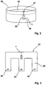
- FIG. 2 shows an above-ground manure tank 28 with manure 29 stored therein.
- the lower ends 22, 32 are about 0.5 m to 1 m above the bottom of the liquid manure tank.
- FIG. 3 shows a schematic plan view of the underground liquid manure drive channel 33 with accesses 34 that is usually used under stables in animal husbandry.
- the device 1 is introduced into the liquid manure drive channel 33 through an access 34 and causes the activation of microorganisms there to produce and promote aerobic composting processes in the manure.
- a central positioning of the device 1 in the manure drive channel 33 is particularly expedient here, since the frequencies and information emanating from the device thus have a large spread.
- the arrangement of the device 1 in the liquid manure 29 is particularly advantageous since the frequencies and information thus propagate particularly well in the liquid manure 29 acting as a carrier medium.
- FIG. 4 shows the device 1 in a sectional side view in the exemplary embodiment.
- a first copper helix 41 and a second copper helix 51 are shown as uncut.
- the first container 20 and the second container 30 extend in a longitudinal direction 40 from the upper end 21, 31 to the lower end 22, 32 for about 50 cm.
- a wall of the first container 20 is formed from a cylindrical PVC tube, with the upper end 21 and the lower end 22 each formed by a PVC cap forming an airtight and watertight seal.
- a beech wood layer 43 in the configuration of a circular 1 cm thick beech wood disc arranged.
- a layer of cotton 44 symmetrically in the longitudinal direction 40 in the direction of the upper end 21 and in the direction of the lower end 22 are a layer of cotton 44, a layer of rock crystal 45, a further layer of cotton 44, a layer of quartz sand 46, a further layer of beech wood 43, and a layer of rose quartz 47 , a further cotton layer 44, a microorganism powder layer 48, and finally a further cotton layer 44 are arranged.
- transitions between the layers run orthogonally to the longitudinal direction 40.
- Each layer has a uniform thickness, with the transitions between the layers being abrupt.
- Layers of organic matter include the beech wood layer 43, the cotton layer 44 and the microorganism powder layer 48.
- the rose quartz layer 47, the quartz sand layer 46 and the rock crystal layer 45 are layers of mineral matter.
- Layers of mineral matter in the container are thick relative to layers of organic matter. The mineral substances therefore also take up significantly more volume in the first container 20 .
- the layers consist of the respective material, i.e. beech wood, cotton, rose quartz, quartz sand or rock crystal. If necessary, the respective substance can be mixed with other substances in the layers.
- Two orgone emitters 42 extend longitudinally 40 centrally in the first container 20.
- a right-handed first copper helix 41 also extends longitudinally centrally between the upper end 21 and the lower end 22 of the first container 20, turns of the first copper helix 41 being the orgone emitters 42 surrounded.
- the rotationally symmetrical orgone emitters 42 have nine ribs 52 formed between grooves at their end regions, which bring about an increase in performance when emitting frequencies and information.
- Acrylic glass tube 55 arranged in the second container 30 .
- a test tube 53 containing activated water 54 is arranged centrally in the acrylic glass tube 55 .
- the acrylic glass tube 55 serves to protect the test tube 53.
- a mini bio-energy accumulator designed as an orgone radiator 42 is arranged at each test tube end 56.
- a rubber stopper 49 is arranged in the test tube 53 in the center 50 of the second container 30 .
- a cotton layer 44 Starting from the middle, in the longitudinal direction 40 and surrounding the acrylic glass tube 55 in the direction of the upper end 31 and the lower end 32 of the second container 30, there is a cotton layer 44, a quartz sand layer 46, another cotton layer 43, a microorganism powder layer 48, as well as Finally, another cotton layer 44 is arranged.
- a second copper spiral 51 extends in the longitudinal direction 40 between the upper end 31 and the lower end 32 of the second container 30, with turns of the second copper spiral 51 surrounding the orgone radiator 42, the test tube 53 and the acrylic glass tube 55.
- the second copper spiral 51 is designed as a left-handed Lakhovsky spiral and the windings run in the area of the PVC pipe forming the wall of the second container 30 .
- the test tubes 53 and the acrylic glass tube 55 are surrounded by the second copper spiral 51 .
- a large part of the volume in the second container 30 is filled by the quartz sand layer 46 .
- the design of the device 1 described here with different materials, layer thicknesses, proportions and distances as well as the activated water 54, the orgone emitter 42 and the first copper spiral 41 in a right-handed design and the second copper spiral 51 in a left-handed design results in strong bioenergetic radiation, transmission power and a generates a wide frequency spectrum.
- microorganisms important for the aerobic decomposition processes such as oxygen-loving bacteria, ammonia-binding moulds, yeasts, ray fungi and earthworms are activated.
Landscapes
- Life Sciences & Earth Sciences (AREA)
- Water Supply & Treatment (AREA)
- Hydrology & Water Resources (AREA)
- Engineering & Computer Science (AREA)
- Environmental & Geological Engineering (AREA)
- Chemical & Material Sciences (AREA)
- Organic Chemistry (AREA)
- Geology (AREA)
- General Life Sciences & Earth Sciences (AREA)
- Health & Medical Sciences (AREA)
- Molecular Biology (AREA)
- Treatment Of Sludge (AREA)
- Biological Treatment Of Waste Water (AREA)
Description
- Die Erfindung betrifft eine Vorrichtung zur Aktivierung von Mikroorganismen in Gülle, umfassend einen ersten Behälter mit einem oberen Ende und einem unteren Ende, mit in dem Behälter angeordnetem organischen Stoff und mineralischen Stoff.
- Aus der
DE 4020914 A1 ist ein Verfahren zur Entfernung oder Verminderung des Ammoniakgehalts aus mit Ammoniak belasteten Gasen unter selektiver Stickstoffbildung unter weitgehender Vermeidung der Bildung von Stickoxiden bekannt. Das Verfahren ist nach einer entsprechenden Vorbehandlung, auch für den Ammoniak oder Ammonium-Ionen-Gehalt von Wässern und Abwässern, beispielsweise landwirtschaftlichen Abwässern, wie Gülle oder Jauche oder kommunalen Wässern, anwendbar. Dabei wird das Ammoniak oder Ammonium-Ionen enthaltende Abwasser auf einen PH-Wert oberhalb von etwa 10,5 gebracht, falls es nicht bereits einen solchen PH-Wert aufweist. Dies kann durch Zusatz von Base, beispielsweise Natronlauge, geschehen. Anschließend wird das Ammoniak zweckmäßigerweise durch Einblasen eines Gases aus dem Wasser ausgetrieben ("Strippen"). Als solches "Stripgas" kann kalte oder erhitzte Luft verwendet werden. Besonders zweckmäßig ist es, dass gereinigte Abgas, das noch heiß aus der katalytischen Reinigung austritt, als Stripgas zu verwenden. Bei einem solchen Verfahren, bei dem Ammoniak oder Ammoniumionengehalt aus Abwässern entfernt werden soll, benötigt man eine Einrichtung, in welcher man das Ammoniak bzw. die Ammonium-Ionen der wässrigen Lösung in die Gasphase überführt. Zweckmäßigerweise sieht man hier einen geschlossenen Behälter vor, welcher einen Zulauf für das Ammoniak oder Ammoniumionen enthaltende Abwasser aufweist, einen Ablauf für das gereinigte Abwasser, eine Zuführung für Strippgas, eine Zuführung für eine Base, beispielsweise Natronlauge, eine Messeinrichtung zur Bestimmung des PH-Werts und der Temperatur, eine Rühreinrichtung und eine Abführung für das ausgetriebene Ammoniak enthaltende Gas. - Dabei benutzt man übliche Festbett- oder Wirbelschichtreaktoren, welche Öffnungen für die Zuführung des zu reinigenden Gases, für die Abführung des gereinigten Gases und gegebenenfalls Öffnungen für Einrichtungen zur Temperaturkontrolle aufweisen. Liegt das katalytische Gemisch als Vollkontakt vor, das heißt ohne Träger, liegen die Katalysatorpartikel zweckmäßigerweise in Form von Pulvern, Granulaten, Kugeln, Perlen, Extrudat oder anderen Schüttgutformen vor. Liegt das katalytisch aktive Gemisch auf einem Träger vor, können im Prinzip beliebige Trägerformen eingesetzt werden. Bei einem Wirbelschichtverfahren empfiehlt es sich, Katalysatorteilchen bzw. Trägerkatalysatorteilchen mit Talghülsen von etwa 0,3 mm bis 0,2 mm Durchmesser einzusetzen, insbesondere in Form von Granulaten, Kugeln, Perlen oder als gebrochenes Extrudat. Dabei wird angegeben, dass das mit Ammoniak belastete Gas bei einer Temperatur zwischen 20° C und 500° C mit einem Katalysator kontaktiert wird, der ein katalytisch aktives Gemisch aus Edelmetall und Übergangsmetalloxide im Molverhältnis 1:10 bis 1:200 aufweist, wobei das Edelmetall ausgewählt ist aus der Platin, Palladium, Rhodium, Iridium und anderen Gemischen umfassenden Gruppe und das Übergangsmetalloxid ausgewählt ist aus der Gruppe der Molybdänoxide, Vanadiumoxide und deren Gemischen.
- Ein Verfahren und eine Vorrichtung der zuvor beschriebenen Art ist mit erheblichen Investitions-, Betriebs-, und Wartungskosten verbunden. Für die Wartung, Austausch und Reparatur von beweglichen Teilen wie beispielsweise ein Rührwerk und Gebläse muss der Betrieb unterbrochen werden. Ferner ist die Prozessüberwachung aufwendig.
- Aus der Veröffentlichung von Dirk Möller "Vitalisiertes Wasser nach dem Vorbild der Natur", Lebensträume von Wolfgang Maiworm, Johanniterhof Seminare vom 31.07.2011, XP055630087 geht ein Aktivator für Wasser hervor.
- Aus der Veröffentlichung von Eckhard Weber "Bioenergie: unermessliches Kraftreservoir", Lebensträume von Wolfgang Maiworm, Johanniterhof Seminare vom 30.09.2008, XP055630089 geht ein Vitalisierer für Gülle hervor.
- Es ist daher die Aufgabe der vorliegenden Erfindung, eine verbesserte Vorrichtung zur Aktivierung von Mikroorganismen in Gülle, insbesondere zur Vitalisierung von Gülle, bereitzustellen, mit der kostengünstig und zuverlässig die für den Rotteprozess der Gülle notwendigen Mikroorganismen aktiviert werden und somit insbesondere auch der Ammoniakgehalt verringert wird.
- Diese Aufgabe wird ausgehend von einer Vorrichtung gemäß dem Oberbegriff des Anspruchs 1 in Verbindung mit den kennzeichnenden Merkmalen gelöst. Vorteilhafte Weiterbildungen der Erfindung sind in den abhängigen Ansprüchen angegeben.
- Die Erfindung schließt die technische Lehre ein, dass der organische Stoff und der mineralische Stoff in dem ersten Behälter in einer Längsrichtung zwischen dem oberen Ende des ersten Behälters und dem unteren Ende des ersten Behälters in Schichten angeordnet ist, und wobei in Längsrichtung von dem unteren Ende zu dem oberen Ende des ersten Behälters aufeinander folgend eine Buchenholzschicht, eine Baumwollschicht, eine Bergkristallschicht, eine weitere Baumwollschicht, eine Quarzsandschicht, eine weitere Buchenholzschicht, eine Rosenquarzschicht, eine weitere Baumwollschicht, eine Mikroorganismen-Pulverschicht und eine weitere Baumwollschicht angeordnet sind, und wobei eine sich in die Längsrichtung erstreckende erste Kupferspirale in dem ersten Behälter angeordnet ist, und wobei der erste Behälter und ein zweiter Behälter parallel nebeneinander angeordnet und verbunden sind, und wobei in dem zweiten Behälter in Längsrichtung von einem unteren Ende des zweiten Behälters zu einem oberen Ende des zweiten Behälters aufeinander folgend eine Baumwollschicht, eine Quarzsandschicht, eine weitere Baumwollschicht, eine Mikroorganismen-Pulverschicht und eine Baumwollschicht angeordnet sind.
- Durch diese geschichtete Anordnung von organischen und mineralischen Stoffen in einem geschlossenen Behälter wird ein Mittel zur kontaktlosen und somit auch wartungsarmen Aktivierung und Stimulierung von für Rotteprozesse der Gülle notwenigen Mikroorganismen bereitgestellt. Dabei erfolgt die Aktivierung der Mikroorganismen durch bioenergetische Strahlung mit speziellen Frequenzen und Informationen, die von der Vorrichtung ausgesendet werden.
- Durch die Förderung der aeroben Rotteprozesse durch die aktivierten Mikroorganismen, kommt es insbesondere zu einer Reduzierung des Ammoniakgehalts und weniger Geruchsbelästigung durch die Gülle. Ferner kommt es zu einer Homogenisierung der Gülle, geringere Grundwasserverschmutzung, geringere Boden- und Pflanzenbelastung nach der Düngung mit vitalisierter Gülle sowie besserer Humusbildung und gute Pflanzenverträglichkeit.
- Ferner werden insbesondere anaerobe, also unter mangelnder Zufuhr von Sauerstoff ablaufende Zersetzungsprozesse vermieden oder zumindest verringert. Damit wird häufiges Aufrühren und Belüften der Gülle überflüssig. Auftretende Folgen wie Ammoniakfreisetzung und Geruchsbelästigung, Blattverätzungen beim Ausbringen der Gülle auf die Felder, eine Schwimmdecke und eine Sinkschicht und umweltbelastende Wirkungen werden vermieden oder zumindest verringert.
- In einer vorteilhaften Weiterbildung der Vorrichtung ist eine sich in Längsrichtung erstreckende rechtsdrehende erste Kupferspirale (Lakhovsky-Spirale) in dem ersten Behälter angeordnet, wobei zwei sich in Längsrichtung erstreckende, insbesondere hintereinander angeordnete Orgonstrahler von der ersten Kupferspirale umgeben sind. Dadurch wird die Aussendung der bioenergetischen Frequenzen und Informationen verstärkt und fokussiert.
- Ein günstiges Frequenzspektrum der bioenergetischen Strahlung kann durch die Anordnung in Längsrichtung von dem unteren Ende zu dem oberen Ende des ersten Behälters mit aufeinanderfolgend einer Buchenholzschicht, einer Baumwollschicht, einer Bergkristallschicht, einer weiteren Baumwollschicht, einer Quarzsandschicht, einer weiteren Buchenholzschicht, einer Rosenquarzschicht, einer weiteren Baumwollschicht, einer Mikroorganismen-Pulverschicht sowie einer weiteren Baumwollschicht erlangt werden.
- In einer nicht zur Erfindung gehörenden Variante der Vorrichtung können mit symmetrischer Abstrahlung und räumlich gleichmäßigen Aktivierung der Mikroorganismen in der Gülle von einer Mitte des ersten Behälters ausgehend ein in Richtung des oberen Endes und/oder in Richtung des unteren Endes aufeinanderfolgend eine Buchenholzschicht, eine Baumwollschicht, eine Bergkristallschicht, eine weitere Baumwollschicht, eine Quarzsandschicht, eine weitere Buchenholzschicht, eine Rosenquarzschicht, eine weitere Baumwollschicht, eine Mikroorganismenpulverschicht, und eine weitere Baumwollschicht angeordnet sein.
- Erfindungsgemäß sind ein erster Behälter und ein zweiter Behälter in Längsrichtung parallel nebeneinander angeordnet ausgerichtet und miteinander verbunden.
- Zur spektralen Ergänzung der Frequenzen sind in dem zweiten Behälter in Längsrichtung von einem unteren Ende des zweiten Behälters zu einem oberen Ende des zweiten Behälters aufeinanderfolgend eine Baumwollschicht, eine Quarzsandschicht, eine weitere Baumwollschicht, eine Mikroorganismen-Pulverschicht und eine Baumwollschicht angeordnet.
- In einer ebenfalls nicht zur Erfindung gehörenden Variante können mit symmetrischer Ausstrahlung und Aussendung von Frequenzen und Informationen zur räumlich gleichmäßigen Aktivierung der Mikroorganismen in der Gülle von der Mitte des zweiten Behälters ausgehend in Richtung des oberen Endes und des unteren Endes aufeinanderfolgend eine Baumwollschicht, eine Quarzsandschicht, eine weitere Baumwollschicht, eine Mikroorganismen-Pulverschicht und eine weitere Baumwollschicht angeordnet sein.
- In einer vorteilhaften Weiterbildung mit stärkerer Sendeleistung und Strahlungsleistung sind in dem zweiten Behälter zwei Reagenzgläser mit darin gehaltenem Aktivwasser umfassend ein Heilquellwasser sowie Mikroorganismen angeordnet, wobei eine sich in Längsrichtung erstreckende zweite Kupferspirale in dem zweiten Behälter angeordnet ist und die Reagenzgläser umgibt. Dabei ist die Kupferspirale zweckmäßigerweise linksdrehend als Lakhovsky-Spirale ausgestaltet. Dadurch werden in Wechselwirkung mit der rechtsdrehenden ersten Kupferspirale ausgleichende Effekte bewirkt, die sich besonders vorteilhaft auf die Mikroorganismen auswirken.
- Die Kupferspirale ist aus Kupfer gefertigt, kann alternativ aber auch aus einer Kupferlegierung gefertigt sein. Das Aktivwasser umfasst ein Heilquellwasser sowie Mikroorganismen. Die Quarzsandschicht, die Bergkristallschicht, die Quarzsandschicht sowie die Rosenquarzschicht bestehen oder beinhalten zumindest den jeweiligen Stoff und sind als mineralischer Stoff zu verstehen. Die Baumwollschicht, die Buchenholzschicht und die Mikroorganismen-Pulverschicht bestehen aus oder beinhalten den jeweiligen Stoff und sind als organischer Stoff zu verstehen.
- Um eine stärkere Fokussierung und Durchdringung der Frequenzen in der Gülle zu bewirken, ist ein Orgonstrahler zwischen einem Reagenzglasende und dem oberen Ende und/oder dem unteren Ende des zweiten Behälters angeordnet. Dabei ist der Orgonstrahler ein aus Metall gefertigter Zylinder mit sich verjüngenden und spitzen Enden.
- Weitere, die Erfindung verbessernde Maßnahmen werden nachstehend gemeinsam mit der Beschreibung eines bevorzugten Ausführungsbeispiels der Erfindung anhand der Figuren näher dargestellt. Es zeigt:
- Fig. 1
- eine erfindungsgemäße Vorrichtung mit einem ersten Behälter und einem zweiten Behälter, die parallel nebeneinander angeordnet und verbunden sind;
- Fig. 2
- in schematischer Ansicht die Vorrichtung in einem oberirdischen Güllebecken;
- Fig. 3
- in schematischer Darstellung die Vorrichtung in einem unterirdischen Gülletreibkanal sowie
- Fig. 4
- die Vorrichtung in einer quergeschnittenen Seitenansicht.
-
Fig. 1 zeigt ein Ausführungsbeispiel der als Gülle-Vitalisierer ausgestalteten Vorrichtung 1 zur Aktivierung von Mikroorganismen in Gülle, umfassend einen ersten Behälter 20 und einen zweiten Behälter 30. Die Behälter 20, 30 sind aus einem zylindrischen PVC-Rohr gefertigt, wobei obere Enden 21, 31 und untere Enden 22, 32 jeweils aus einer PVC-Kappe gefertigt sind und mit dem PVC-Rohr den luft- und wasserdichten ersten Behälter 20 und zweiten Behälter 30 ausbilden. An den oberen Enden 21, 31 und den unteren Enden 22, 32 ist jeweils eine Ringschraube 23 zur Aufnahme einer aus Stahl gefertigten Gewindestange 24 ausgebildet. Die Gewindestange 24 ist mit Stahlschrauben 25 an den Ringschrauben 23 befestigt. Somit sind das obere Ende 21 des ersten Behälters 20 und das obere Ende 31 des zweiten Behälters 30 über die Gewindestange 24 fest miteinander verbunden. Eine weitere Gewindestange 24 verbindet das untere Ende 22 des ersten Behälters 20 mit dem unteren Ende 32 des zweiten Behälters 30 durch Verschraubung mit den Stahlschrauben 25. Ein Bügel 26 ist zwischen den oberen Ende 21 des ersten Behälters 20 und dem oberen Ende 31 des zweiten Behälters 30 an der Gewindestange 24 befestigt. Der Bügel 26 dient zur Aufnahme eines Seils oder einer Kette, mit der die Vorrichtung 1 hängend transportiert oder gehalten werden kann. Der erste Behälter 20 und der zweite Behälter 30 sind durch die Befestigung mit Schrauben 25 an der Gewindestange 24 fest miteinander verbunden und parallel ausgerichtet. Da die Stahlschrauben 25 jeweils auf gegenüberliegenden Seiten der Ringschraube 23 auf der Gewindestange 24 angeordnet sind, wird durch eine Klemmung eine starre Verbindung mit fest definierter Ausrichtung und Beabstandung zwischen dem ersten Behälter 20 und dem zweiten Behälter 30 ermöglicht. Eine Ausrichtung und Veränderung des Abstandes zwischen dem ersten Behälter 20 und dem zweiten Behälter 30 können durch Anpassung einer Position der Schrauben 25 auf der Gewindestange 24 erfolgen. Somit ist eine Feinjustierung und Einstellung einer Interferenz von bioenergetischen Strahlungswellen des ersten Behälters 20 und des zweiten Behälters 30 möglich. Im Ergebnis können damit besonders hohe bioenergetische Wirkleistung erzielt werden. -
Fig. 2 zeigt ein oberirdisches Güllebecken 28 mit darin bevorrateter Gülle 29. Die Vorrichtung 1 ist an einem Seil 27 hängend in der Gülle 29 des Güllebeckens 28 eingelassen. Die unteren Enden 22, 32 befinden sich dabei ca. 0,5 m bis 1 m über dem Boden des Güllebeckens. -
Fig. 3 zeigt in schematischer Draufsicht üblicherweise unter Stallungen in der Viehhaltung zur Anwendung kommende unterirdische Gülletreibkanal 33 mit Zugängen 34. Durch einen Zugang 34 ist die Vorrichtung 1 in den Gülle-Treibkanal 33 eingebracht und bewirkt dort die Aktivierung von Mikroorganismen zur Erzeugung und Förderung von aeroben Rotteprozessen in der Gülle. Dabei ist insbesondere eine zentrale Positionierung der Vorrichtung 1 in dem Gülle-Treibkanal 33 zweckmäßig, da somit die von der Vorrichtung ausgehenden Frequenzen und Informationen eine große Ausbreitung haben. Die Anordnung der Vorrichtung 1 in der Gülle 29 ist besonders vorteilhaft, da sich somit die Frequenzen und Informationen besonders gut in der als Trägermedium fungierenden Gülle 29 ausbreiten. -
Fig. 4 zeigt in dem Ausführungsbeispiel die Vorrichtung 1 in einer geschnittenen Seitenansicht. In dieser Ansicht sind eine erste Kupferspirale 41 und eine zweite Kupferspirale 51 als nicht geschnitten dargestellt. Der erste Behälter 20 und der zweite Behälter 30 erstrecken sich in einer Längsrichtung 40 von dem oberen Ende 21, 31 zu dem unteren Ende 22, 32 über ca. 50 cm. Zwischen der Ringschraube 23 am oberen Ende 21 des ersten Behälters 20 und der Ringschraube 23 am oberen Ende 31 des zweiten Behälters 30, die über die Gewindestange 24 verbunden sind, liegen ca. 10 cm. Eine Wandung des ersten Behälters 20 ist aus einem zylindrischen PVC-Rohr gebildet, wobei das obere Ende 21 und das untere Ende 22 jeweils durch eine PVC-Kappe gebildet einen luft- und wasserdichten Verschluss bilden. In einer Mitte 50 des ersten Behälters 20 ist eine Buchenholzschicht 43 in Ausgestaltung einer kreisrunden 1 cm dicken Buchenholzscheibe angeordnet. Von dieser Buchenholzschicht 43 ausgehend sind symmetrisch in Längsrichtung 40 in Richtung des oberen Endes 21 und in Richtung des unteren Endes 22 aufeinander folgend eine Baumwollschicht 44, eine Bergkristallschicht 45, eine weitere Baumwollschicht 44, eine Quarzsandschicht 46, eine weitere Buchenholzschicht 43, eine Rosenquarzschicht 47, eine weitere Baumwollschicht 44, eine Mikroorganismen-Pulverschicht 48, sowie abschließend eine weitere Baumwollschicht 44 angeordnet. Dabei verlaufen Übergänge zwischen den Schichten orthogonal zu der Längsrichtung 40. Eine jeweilige Schicht weist eine gleichmäßige Dicke auf wobei die Übergänge zwischen den Schichten abrupt sind. Schichten aus organischem Stoff umfassen die Buchenholzschicht 43, die Baumwollschicht 44, sowie die Mikroorganismen-Pulverschicht 48. Die Rosenquarzschicht 47, die Quarzsandschicht 46 sowie die Bergkristallschicht 45 sind als Schichten aus mineralischem Stoff anzusehen. Schichten aus mineralischem Stoff in dem Behälter sind im Verhältnis zu Schichten aus organischem Stoff dick. Somit nehmen die mineralischen Stoffe auch deutlich mehr Volumen in den ersten Behälter 20 ein. Die Schichten bestehen aus dem jeweiligen Stoff, also Buchenholz, Baumwolle, Rosenquarz, Quarzsand beziehungsweise Bergkristall. Gegebenenfalls kann der jeweilige Stoff mit anderen Stoffen gemischt in den Schichten vorkommen. Zwei Orgonstrahler 42 verlaufen sich in Längsrichtung 40 erstreckend zentral in dem ersten Behälter 20. Eine rechtsdrehende erste Kupferspirale 41 erstreckt sich ebenfalls in Längsrichtung zentral zwischen den oberen Ende 21 und den unteren Ende 22 des ersten Behälters 20, wobei Windungen der ersten Kupferspirale 41 die Orgonstrahler 42 umgeben. Die rotationssymmetrischen Orgonstrahler 42 weisen an ihren Endbereichen neun, zwischen Rillen ausgebildete, Rippen 52 auf, durch die eine Leistungssteigerung bei der Aussendung von Frequenzen und Informationen bewirkt wird. In dem zweiten Behälter 30 ist von der Mitte 50 ausgehend ein sich in Längsrichtung 40 erstreckendes Acrylglasrohr 55 angeordnet. In dem Acrylglasrohr 55 ist ein Aktivwasser 54 beinhaltendes Reagenzglas 53 zentral angeordnet. Das Acrylglasrohr 55 dient zum Schutz des Reagenzglases 53. Im Bereich des oberen Endes 31 und des unteren Endes 32 des zweiten Behälters 30 sind an Reagenzglasenden 56 jeweils ein als Orgonstrahler 42 ausgebildeter Minibioenergieakkumulator angeordnet. In der Mitte 50 des zweiten Behälters 30 ist im Reagenzglas 53 ein Gummistopfen 49 angeordnet. Von der Mitte ausgehend sind sich in Längsrichtung 40 aufeinanderfolgend und das Acrylglasrohr 55 umgebend in Richtung des oberen Endes 31 und des unteren Endes 32 des zweiten Behälters 30 eine Baumwollschicht 44, eine Quarzsandschicht 46, eine weitere Baumwollschicht 43, eine Mikroorganismen-Pulverschicht 48, sowie abschließend eine weitere Baumwollschicht 44 angeordnet. Eine zweite Kupferspirale 51 erstreckt sich in Längsrichtung 40 zwischen dem oberen Ende 31 und dem unteren Ende 32 des zweiten Behälters 30, wobei Windungen der zweiten Kupferspirale 51 den Orgonstrahler 42, sowie das Reagenzglas 53 und das Acrylglasrohr 55 umgeben. - Die zweite Kupferspirale 51 ist als linksdrehende Lakhovsky-Spirale ausgebildet und die Windungen verlaufen im Bereich des die Wandung des zweiten Behälters 30 bildenden PVC-Rohres. Die Reagenzgläser 53 und das Acrylglasrohr 55 sind von der zweiten Kupferspirale 51 umgeben. Einen Großteil des Volumens im zweiten Behälter 30 wird durch die Quarzsandschicht 46 ausgefüllt. Durch die hier beschriebene Ausgestaltung der Vorrichtung 1 mit verschiedenen Stoffen, Schichtdicken, Proportionen und Abständen sowie dem Aktivwasser 54, dem Orgonstrahler 42 und der ersten Kupferspirale 41 in rechtsdrehender Ausgestaltung und der zweiten Kupferspirale 51 in linksdrehender Ausgestaltung wird eine starke bioenergetische Strahlung, Sendeleistung und ein breites Frequenzspektrum erzeugt. Dadurch werden für die aeroben Zersetzungsprozesse wichtige Mikroorganismen, wie sauerstoffliebende Bakterien, ammoniakbindende Schimmelpilze, Hefen, Strahlenpilze sowie Regenwürmer aktiviert.
-
- 1
- Vorrichtung
- 20
- erster Behälter
- 21
- oberes Ende
- 22
- unteres Ende
- 23
- Ringschraube
- 24
- Gewindestange
- 25
- Stahlschrauben
- 26
- Bügel
- 27
- Seil
- 28
- Gülle-Becken
- 29
- Gülle
- 30
- zweiter Behälter
- 31
- oberes Ende
- 32
- unteres Ende
- 33
- Gülle-Treibkanäle
- 34
- Zugang
- 40
- Längsrichtung
- 41
- erste Kupferspirale
- 42
- Orgonstrahler
- 43
- Buchenholzschicht
- 44
- Baumwollschicht
- 45
- Bergkristallschicht
- 46
- Quarzsandschicht
- 47
- Rosenquarzschicht
- 48
- Mikroorganismen-Pulverschicht
- 49
- Gummistopfen
- 50
- Mitte
- 51
- zweite Kupferspirale
- 52
- Rippe
- 53
- Reagenzglas
- 54
- Aktivwasser
- 55
- Acrylglasrohr
- 56
- Reagenzglasende
Claims (4)
- Vorrichtung (1) zur Aktivierung von Mikroorganismen in Gülle, umfassend einen ersten Behälter (20) mit einem oberen Ende (21) und mit einem unteren Ende (22), mit in dem Behälter (20) angeordnetem organischen Stoff und mineralischen Stoff, wobeider organische Stoff und der mineralische Stoff in dem ersten Behälter (20) in einer Längsrichtung (40) zwischen dem oberen Ende (21) des ersten Behälters (20) und dem unteren Ende (22) des ersten Behälters (20) in Schichten angeordnet ist, und wobei in Längsrichtung (40) von dem unteren Ende (22) zu dem oberen Ende (21) des ersten Behälters (20) aufeinander folgend eine Buchenholzschicht (43), eine Baumwollschicht (44), eine Bergkristallschicht (45), eine weitere Baumwollschicht (44), eine Quarzsandschicht (46), eine weitere Buchenholzschicht (43), eine Rosenquarzschicht (47), eine weitere Baumwollschicht (44), eine Mikroorganismen-Pulverschicht (48) und eine weitere Baumwollschicht (44) angeordnet sind, und wobei eine sich in die Längsrichtung (40) erstreckende erste Kupferspirale (41) in dem ersten Behälter (20) angeordnet ist,und wobeider erste Behälter (20) und ein zweiter Behälter (30) parallel nebeneinander angeordnet und verbunden sind, und wobei in dem zweiten Behälter (30) in Längsrichtung (40) von einem unteren Ende (32) des zweiten Behälters (30) zu einem oberen Ende (31) des zweiten Behälters (30) aufeinander folgend eine Baumwollschicht (44), eine Quarzsandschicht (46), eine weitere Baumwollschicht (44), eine Mikroorganismen-Pulverschicht (48) und eine Baumwollschicht (44) angeordnet sind.
- Vorrichtung (1) nach Anspruch 1,
dadurch gekennzeichnet,
dass eine sich in die Längsrichtung (40) erstreckende zweite Kupferspirale (51) in dem zweiten Behälter (30) angeordnet ist. - Vorrichtung (1) nach Anspruch 1 oder 2,
dadurch gekennzeichnet,
dass in dem zweiten Behälter (30) zwei Reagenzgläser (52) mit darin gehaltenem Aktivwasser (54) umfassend ein Heilquellwasser sowie Mikroorganismen angeordnet sind. - Vorrichtung (1) nach Anspruch 3,
dadurch gekennzeichnet,
dass die Reagenzgläser (52) von der zweiten Kupferspirale (51) umgeben sind.
Applications Claiming Priority (1)
| Application Number | Priority Date | Filing Date | Title |
|---|---|---|---|
| DE202018104431.1U DE202018104431U1 (de) | 2018-08-01 | 2018-08-01 | Gülle-Vitalisierer |
Publications (2)
| Publication Number | Publication Date |
|---|---|
| EP3604231A1 EP3604231A1 (de) | 2020-02-05 |
| EP3604231B1 true EP3604231B1 (de) | 2022-06-15 |
Family
ID=63450093
Family Applications (1)
| Application Number | Title | Priority Date | Filing Date |
|---|---|---|---|
| EP19181986.1A Active EP3604231B1 (de) | 2018-08-01 | 2019-06-24 | Gülle-vitalisierer |
Country Status (2)
| Country | Link |
|---|---|
| EP (1) | EP3604231B1 (de) |
| DE (1) | DE202018104431U1 (de) |
Family Cites Families (3)
| Publication number | Priority date | Publication date | Assignee | Title |
|---|---|---|---|---|
| DE4020914A1 (de) | 1990-06-30 | 1992-01-02 | Solvay Umweltchemie Gmbh | Verfahren zur entfernung des ammoniak-gehaltes in gasen |
| DE59911370D1 (de) * | 1999-08-09 | 2005-02-03 | Lindtner Monika | Trinkwasser-Durchströmungsgerät für Wasserleitungen |
| DE202011005559U1 (de) * | 2011-04-24 | 2011-10-07 | Christian Lange | Eiförmiges Durchströmgerät nach goldenem Schnitt zur bioenergetischen Vitalisierung von Wasser |
-
2018
- 2018-08-01 DE DE202018104431.1U patent/DE202018104431U1/de active Active
-
2019
- 2019-06-24 EP EP19181986.1A patent/EP3604231B1/de active Active
Also Published As
| Publication number | Publication date |
|---|---|
| DE202018104431U1 (de) | 2018-08-16 |
| EP3604231A1 (de) | 2020-02-05 |
Similar Documents
| Publication | Publication Date | Title |
|---|---|---|
| DE10330959B4 (de) | Biologischer Nachrüstsatz | |
| EP0441169B1 (de) | Verfahren und Vorrichtung zur in-situ-Sanierung kontaminierter Bereiche | |
| DE673066C (de) | Verfahren und Vorrichtung zur Herstellung von Duengemitteln, Bodenverbesserungsmitteln oder gesundheitlich unschaedlichen Stoffen aus organischen Abfallstoffen pflanzlichen oder tierischen Ursprungs | |
| DE102013009961A1 (de) | Drehrohr und Drehrohrofen zur Herstel1ung von Aktivkohle | |
| DE112015003668B4 (de) | Verfahren und vorrichtung zur selektiven entgasung von methan aus waschflüssigkeit sowie verwendung einer vorrichtung zur selektiven entgasung von methan aus waschflüssigkeit | |
| DD283988A5 (de) | Vorrichtung und verfahren zum kompostieren von in fluessiger form vorliegenden abfaellen, wie guelle, abwasser, klaerschlamm oder dergleichen | |
| DE3023428A1 (de) | Verfahren und vorrichtung zum aufbereiten von guelle | |
| DE102013006266A1 (de) | Verfahren und Vorrichtung zur aeroben mikrobiologischen Erwärmung schüttfähiger feuchter organischer Feststoffe | |
| EP3604231A1 (de) | Gülle-vitalisierer | |
| EP1444170B1 (de) | Mikrobiologische energiequelle zum antrieb eines verbrauchers | |
| EP3247786B1 (de) | Vorrichtung zur elektrischen desintegration von zellverbänden, sowie anlage und verwendung der vorrichtung zur herstellung von futtermittelzwischenprodukten und futtermittelprodukten | |
| DE19717669B4 (de) | Verfahren zur Schwermetallentfrachtung von biogen-organischen Substraten | |
| EP0261516A2 (de) | Verfahren zur kontinuierlichen mikrobiologischen Denitrifikation von Grundwasser | |
| DE10101980A1 (de) | Vorrichtung zur Behandlung eines Schüttguts, insbesondere Korkgranulat | |
| DE102012002964B3 (de) | Vorrichtung zur Gewinnung von Biogas | |
| DE10155760B4 (de) | Verfahren zur in situ-Entsäuerung schwefelsauren Wassers | |
| DE102011050623B4 (de) | Rührvorrichtung | |
| DE3623242A1 (de) | Verfahren zur behandlung von hochbelasteten und organisch abbaubaren, stickstoffreichen abwaessern | |
| DE102005050414A1 (de) | Optoreaktor | |
| DE10129541B4 (de) | Verfahren und Vorrichtung zur Reinigung von Abwasser | |
| EP3186212B1 (de) | Anlage zur düngemittelherstellung aus organischen abfällen sowie verfahren zur düngemittelherstellung aus organischen abfällen | |
| EP0853241A2 (de) | Verfahren und Vorrichtung zur Grundwassertestung | |
| EP2764930A1 (de) | Anlage und Verfahren zum Behandeln einer Deponie | |
| DE19617973C1 (de) | Faulkammer, insbesondere für biologische Kläranlagen | |
| DE19820645B4 (de) | Verfahren zur Reduzierung der Freisetzung von flüchtigen Emittenten aus einer Flüssigkeit |
Legal Events
| Date | Code | Title | Description |
|---|---|---|---|
| PUAI | Public reference made under article 153(3) epc to a published international application that has entered the european phase |
Free format text: ORIGINAL CODE: 0009012 |
|
| STAA | Information on the status of an ep patent application or granted ep patent |
Free format text: STATUS: THE APPLICATION HAS BEEN PUBLISHED |
|
| AK | Designated contracting states |
Kind code of ref document: A1 Designated state(s): AL AT BE BG CH CY CZ DE DK EE ES FI FR GB GR HR HU IE IS IT LI LT LU LV MC MK MT NL NO PL PT RO RS SE SI SK SM TR |
|
| AX | Request for extension of the european patent |
Extension state: BA ME |
|
| STAA | Information on the status of an ep patent application or granted ep patent |
Free format text: STATUS: REQUEST FOR EXAMINATION WAS MADE |
|
| 17P | Request for examination filed |
Effective date: 20200327 |
|
| RBV | Designated contracting states (corrected) |
Designated state(s): AL AT BE BG CH CY CZ DE DK EE ES FI FR GB GR HR HU IE IS IT LI LT LU LV MC MK MT NL NO PL PT RO RS SE SI SK SM TR |
|
| STAA | Information on the status of an ep patent application or granted ep patent |
Free format text: STATUS: EXAMINATION IS IN PROGRESS |
|
| 17Q | First examination report despatched |
Effective date: 20210224 |
|
| GRAP | Despatch of communication of intention to grant a patent |
Free format text: ORIGINAL CODE: EPIDOSNIGR1 |
|
| STAA | Information on the status of an ep patent application or granted ep patent |
Free format text: STATUS: GRANT OF PATENT IS INTENDED |
|
| RIC1 | Information provided on ipc code assigned before grant |
Ipc: C02F 101/16 20060101ALN20211217BHEP Ipc: C02F 11/02 20060101ALI20211217BHEP Ipc: C02F 1/00 20060101AFI20211217BHEP |
|
| INTG | Intention to grant announced |
Effective date: 20220119 |
|
| GRAS | Grant fee paid |
Free format text: ORIGINAL CODE: EPIDOSNIGR3 |
|
| GRAA | (expected) grant |
Free format text: ORIGINAL CODE: 0009210 |
|
| STAA | Information on the status of an ep patent application or granted ep patent |
Free format text: STATUS: THE PATENT HAS BEEN GRANTED |
|
| AK | Designated contracting states |
Kind code of ref document: B1 Designated state(s): AL AT BE BG CH CY CZ DE DK EE ES FI FR GB GR HR HU IE IS IT LI LT LU LV MC MK MT NL NO PL PT RO RS SE SI SK SM TR |
|
| REG | Reference to a national code |
Ref country code: CH Ref legal event code: EP Ref country code: GB Ref legal event code: FG4D Free format text: NOT ENGLISH |
|
| REG | Reference to a national code |
Ref country code: IE Ref legal event code: FG4D Free format text: LANGUAGE OF EP DOCUMENT: GERMAN |
|
| REG | Reference to a national code |
Ref country code: DE Ref legal event code: R096 Ref document number: 502019004625 Country of ref document: DE |
|
| REG | Reference to a national code |
Ref country code: AT Ref legal event code: REF Ref document number: 1498307 Country of ref document: AT Kind code of ref document: T Effective date: 20220715 |
|
| REG | Reference to a national code |
Ref country code: NL Ref legal event code: FP |
|
| REG | Reference to a national code |
Ref country code: LT Ref legal event code: MG9D |
|
| PG25 | Lapsed in a contracting state [announced via postgrant information from national office to epo] |
Ref country code: SE Free format text: LAPSE BECAUSE OF FAILURE TO SUBMIT A TRANSLATION OF THE DESCRIPTION OR TO PAY THE FEE WITHIN THE PRESCRIBED TIME-LIMIT Effective date: 20220615 Ref country code: NO Free format text: LAPSE BECAUSE OF FAILURE TO SUBMIT A TRANSLATION OF THE DESCRIPTION OR TO PAY THE FEE WITHIN THE PRESCRIBED TIME-LIMIT Effective date: 20220915 Ref country code: LT Free format text: LAPSE BECAUSE OF FAILURE TO SUBMIT A TRANSLATION OF THE DESCRIPTION OR TO PAY THE FEE WITHIN THE PRESCRIBED TIME-LIMIT Effective date: 20220615 Ref country code: HR Free format text: LAPSE BECAUSE OF FAILURE TO SUBMIT A TRANSLATION OF THE DESCRIPTION OR TO PAY THE FEE WITHIN THE PRESCRIBED TIME-LIMIT Effective date: 20220615 Ref country code: GR Free format text: LAPSE BECAUSE OF FAILURE TO SUBMIT A TRANSLATION OF THE DESCRIPTION OR TO PAY THE FEE WITHIN THE PRESCRIBED TIME-LIMIT Effective date: 20220916 Ref country code: FI Free format text: LAPSE BECAUSE OF FAILURE TO SUBMIT A TRANSLATION OF THE DESCRIPTION OR TO PAY THE FEE WITHIN THE PRESCRIBED TIME-LIMIT Effective date: 20220615 Ref country code: BG Free format text: LAPSE BECAUSE OF FAILURE TO SUBMIT A TRANSLATION OF THE DESCRIPTION OR TO PAY THE FEE WITHIN THE PRESCRIBED TIME-LIMIT Effective date: 20220915 |
|
| PG25 | Lapsed in a contracting state [announced via postgrant information from national office to epo] |
Ref country code: RS Free format text: LAPSE BECAUSE OF FAILURE TO SUBMIT A TRANSLATION OF THE DESCRIPTION OR TO PAY THE FEE WITHIN THE PRESCRIBED TIME-LIMIT Effective date: 20220615 Ref country code: LV Free format text: LAPSE BECAUSE OF FAILURE TO SUBMIT A TRANSLATION OF THE DESCRIPTION OR TO PAY THE FEE WITHIN THE PRESCRIBED TIME-LIMIT Effective date: 20220615 |
|
| PG25 | Lapsed in a contracting state [announced via postgrant information from national office to epo] |
Ref country code: SM Free format text: LAPSE BECAUSE OF FAILURE TO SUBMIT A TRANSLATION OF THE DESCRIPTION OR TO PAY THE FEE WITHIN THE PRESCRIBED TIME-LIMIT Effective date: 20220615 Ref country code: SK Free format text: LAPSE BECAUSE OF FAILURE TO SUBMIT A TRANSLATION OF THE DESCRIPTION OR TO PAY THE FEE WITHIN THE PRESCRIBED TIME-LIMIT Effective date: 20220615 Ref country code: RO Free format text: LAPSE BECAUSE OF FAILURE TO SUBMIT A TRANSLATION OF THE DESCRIPTION OR TO PAY THE FEE WITHIN THE PRESCRIBED TIME-LIMIT Effective date: 20220615 Ref country code: PT Free format text: LAPSE BECAUSE OF FAILURE TO SUBMIT A TRANSLATION OF THE DESCRIPTION OR TO PAY THE FEE WITHIN THE PRESCRIBED TIME-LIMIT Effective date: 20221017 Ref country code: ES Free format text: LAPSE BECAUSE OF FAILURE TO SUBMIT A TRANSLATION OF THE DESCRIPTION OR TO PAY THE FEE WITHIN THE PRESCRIBED TIME-LIMIT Effective date: 20220615 Ref country code: EE Free format text: LAPSE BECAUSE OF FAILURE TO SUBMIT A TRANSLATION OF THE DESCRIPTION OR TO PAY THE FEE WITHIN THE PRESCRIBED TIME-LIMIT Effective date: 20220615 Ref country code: CZ Free format text: LAPSE BECAUSE OF FAILURE TO SUBMIT A TRANSLATION OF THE DESCRIPTION OR TO PAY THE FEE WITHIN THE PRESCRIBED TIME-LIMIT Effective date: 20220615 |
|
| PG25 | Lapsed in a contracting state [announced via postgrant information from national office to epo] |
Ref country code: PL Free format text: LAPSE BECAUSE OF FAILURE TO SUBMIT A TRANSLATION OF THE DESCRIPTION OR TO PAY THE FEE WITHIN THE PRESCRIBED TIME-LIMIT Effective date: 20220615 Ref country code: IS Free format text: LAPSE BECAUSE OF FAILURE TO SUBMIT A TRANSLATION OF THE DESCRIPTION OR TO PAY THE FEE WITHIN THE PRESCRIBED TIME-LIMIT Effective date: 20221015 |
|
| REG | Reference to a national code |
Ref country code: DE Ref legal event code: R097 Ref document number: 502019004625 Country of ref document: DE |
|
| PG25 | Lapsed in a contracting state [announced via postgrant information from national office to epo] |
Ref country code: MC Free format text: LAPSE BECAUSE OF FAILURE TO SUBMIT A TRANSLATION OF THE DESCRIPTION OR TO PAY THE FEE WITHIN THE PRESCRIBED TIME-LIMIT Effective date: 20220615 Ref country code: AL Free format text: LAPSE BECAUSE OF FAILURE TO SUBMIT A TRANSLATION OF THE DESCRIPTION OR TO PAY THE FEE WITHIN THE PRESCRIBED TIME-LIMIT Effective date: 20220615 |
|
| PLBE | No opposition filed within time limit |
Free format text: ORIGINAL CODE: 0009261 |
|
| STAA | Information on the status of an ep patent application or granted ep patent |
Free format text: STATUS: NO OPPOSITION FILED WITHIN TIME LIMIT |
|
| PG25 | Lapsed in a contracting state [announced via postgrant information from national office to epo] |
Ref country code: LU Free format text: LAPSE BECAUSE OF NON-PAYMENT OF DUE FEES Effective date: 20220624 Ref country code: DK Free format text: LAPSE BECAUSE OF FAILURE TO SUBMIT A TRANSLATION OF THE DESCRIPTION OR TO PAY THE FEE WITHIN THE PRESCRIBED TIME-LIMIT Effective date: 20220615 |
|
| 26N | No opposition filed |
Effective date: 20230316 |
|
| PG25 | Lapsed in a contracting state [announced via postgrant information from national office to epo] |
Ref country code: SI Free format text: LAPSE BECAUSE OF FAILURE TO SUBMIT A TRANSLATION OF THE DESCRIPTION OR TO PAY THE FEE WITHIN THE PRESCRIBED TIME-LIMIT Effective date: 20220615 |
|
| PG25 | Lapsed in a contracting state [announced via postgrant information from national office to epo] |
Ref country code: IT Free format text: LAPSE BECAUSE OF FAILURE TO SUBMIT A TRANSLATION OF THE DESCRIPTION OR TO PAY THE FEE WITHIN THE PRESCRIBED TIME-LIMIT Effective date: 20220615 |
|
| PG25 | Lapsed in a contracting state [announced via postgrant information from national office to epo] |
Ref country code: MK Free format text: LAPSE BECAUSE OF FAILURE TO SUBMIT A TRANSLATION OF THE DESCRIPTION OR TO PAY THE FEE WITHIN THE PRESCRIBED TIME-LIMIT Effective date: 20220615 Ref country code: CY Free format text: LAPSE BECAUSE OF FAILURE TO SUBMIT A TRANSLATION OF THE DESCRIPTION OR TO PAY THE FEE WITHIN THE PRESCRIBED TIME-LIMIT Effective date: 20220615 |
|
| PG25 | Lapsed in a contracting state [announced via postgrant information from national office to epo] |
Ref country code: HU Free format text: LAPSE BECAUSE OF FAILURE TO SUBMIT A TRANSLATION OF THE DESCRIPTION OR TO PAY THE FEE WITHIN THE PRESCRIBED TIME-LIMIT; INVALID AB INITIO Effective date: 20190624 |
|
| PGFP | Annual fee paid to national office [announced via postgrant information from national office to epo] |
Ref country code: IE Payment date: 20240619 Year of fee payment: 6 |
|
| PGFP | Annual fee paid to national office [announced via postgrant information from national office to epo] |
Ref country code: GB Payment date: 20240621 Year of fee payment: 6 |
|
| PGFP | Annual fee paid to national office [announced via postgrant information from national office to epo] |
Ref country code: NL Payment date: 20240619 Year of fee payment: 6 |
|
| PGFP | Annual fee paid to national office [announced via postgrant information from national office to epo] |
Ref country code: FR Payment date: 20240628 Year of fee payment: 6 |
|
| PGFP | Annual fee paid to national office [announced via postgrant information from national office to epo] |
Ref country code: BE Payment date: 20240619 Year of fee payment: 6 |
|
| PG25 | Lapsed in a contracting state [announced via postgrant information from national office to epo] |
Ref country code: MT Free format text: LAPSE BECAUSE OF FAILURE TO SUBMIT A TRANSLATION OF THE DESCRIPTION OR TO PAY THE FEE WITHIN THE PRESCRIBED TIME-LIMIT Effective date: 20220615 |
|
| PG25 | Lapsed in a contracting state [announced via postgrant information from national office to epo] |
Ref country code: BG Free format text: LAPSE BECAUSE OF FAILURE TO SUBMIT A TRANSLATION OF THE DESCRIPTION OR TO PAY THE FEE WITHIN THE PRESCRIBED TIME-LIMIT Effective date: 20220615 |
|
| PG25 | Lapsed in a contracting state [announced via postgrant information from national office to epo] |
Ref country code: BG Free format text: LAPSE BECAUSE OF FAILURE TO SUBMIT A TRANSLATION OF THE DESCRIPTION OR TO PAY THE FEE WITHIN THE PRESCRIBED TIME-LIMIT Effective date: 20220615 |
|
| PGFP | Annual fee paid to national office [announced via postgrant information from national office to epo] |
Ref country code: DE Payment date: 20250430 Year of fee payment: 7 |
|
| PGFP | Annual fee paid to national office [announced via postgrant information from national office to epo] |
Ref country code: AT Payment date: 20250620 Year of fee payment: 7 |
|
| PGFP | Annual fee paid to national office [announced via postgrant information from national office to epo] |
Ref country code: CH Payment date: 20250701 Year of fee payment: 7 |
|
| PG25 | Lapsed in a contracting state [announced via postgrant information from national office to epo] |
Ref country code: TR Free format text: LAPSE BECAUSE OF FAILURE TO SUBMIT A TRANSLATION OF THE DESCRIPTION OR TO PAY THE FEE WITHIN THE PRESCRIBED TIME-LIMIT Effective date: 20220615 |
|
| REG | Reference to a national code |
Ref country code: NL Ref legal event code: MM Effective date: 20250701 |
|
| GBPC | Gb: european patent ceased through non-payment of renewal fee |
Effective date: 20250624 |
|
| REG | Reference to a national code |
Ref country code: BE Ref legal event code: MM Effective date: 20250630 |
|
| PG25 | Lapsed in a contracting state [announced via postgrant information from national office to epo] |
Ref country code: NL Free format text: LAPSE BECAUSE OF NON-PAYMENT OF DUE FEES Effective date: 20250701 |
|
| PG25 | Lapsed in a contracting state [announced via postgrant information from national office to epo] |
Ref country code: GB Free format text: LAPSE BECAUSE OF NON-PAYMENT OF DUE FEES Effective date: 20250624 |
|
| PG25 | Lapsed in a contracting state [announced via postgrant information from national office to epo] |
Ref country code: IE Free format text: LAPSE BECAUSE OF NON-PAYMENT OF DUE FEES Effective date: 20250624 |
|
| PG25 | Lapsed in a contracting state [announced via postgrant information from national office to epo] |
Ref country code: BE Free format text: LAPSE BECAUSE OF NON-PAYMENT OF DUE FEES Effective date: 20250630 |
|
| PG25 | Lapsed in a contracting state [announced via postgrant information from national office to epo] |
Ref country code: FR Free format text: LAPSE BECAUSE OF NON-PAYMENT OF DUE FEES Effective date: 20250630 |