EP3604190A1 - Elevator management system, and method for managing elevator - Google Patents
Elevator management system, and method for managing elevator Download PDFInfo
- Publication number
- EP3604190A1 EP3604190A1 EP17901590.4A EP17901590A EP3604190A1 EP 3604190 A1 EP3604190 A1 EP 3604190A1 EP 17901590 A EP17901590 A EP 17901590A EP 3604190 A1 EP3604190 A1 EP 3604190A1
- Authority
- EP
- European Patent Office
- Prior art keywords
- information
- cage
- elevator
- cages
- control apparatus
- Prior art date
- Legal status (The legal status is an assumption and is not a legal conclusion. Google has not performed a legal analysis and makes no representation as to the accuracy of the status listed.)
- Granted
Links
Images






Classifications
-
- B—PERFORMING OPERATIONS; TRANSPORTING
- B66—HOISTING; LIFTING; HAULING
- B66B—ELEVATORS; ESCALATORS OR MOVING WALKWAYS
- B66B1/00—Control systems of elevators in general
- B66B1/02—Control systems without regulation, i.e. without retroactive action
- B66B1/06—Control systems without regulation, i.e. without retroactive action electric
- B66B1/14—Control systems without regulation, i.e. without retroactive action electric with devices, e.g. push-buttons, for indirect control of movements
- B66B1/18—Control systems without regulation, i.e. without retroactive action electric with devices, e.g. push-buttons, for indirect control of movements with means for storing pulses controlling the movements of several cars or cages
-
- B—PERFORMING OPERATIONS; TRANSPORTING
- B66—HOISTING; LIFTING; HAULING
- B66B—ELEVATORS; ESCALATORS OR MOVING WALKWAYS
- B66B1/00—Control systems of elevators in general
- B66B1/24—Control systems with regulation, i.e. with retroactive action, for influencing travelling speed, acceleration, or deceleration
- B66B1/2408—Control systems with regulation, i.e. with retroactive action, for influencing travelling speed, acceleration, or deceleration where the allocation of a call to an elevator car is of importance, i.e. by means of a supervisory or group controller
- B66B1/2458—For elevator systems with multiple shafts and a single car per shaft
Definitions
- the present invention relates to an elevator management system and an elevator management method and relates to, for example, an elevator management system for managing a plurality of cages, which operate between a plurality of floors, as a group.
- this type of elevator management system moves cages between the lowest floor and the highest floor so that the distances between the plurality of cages in a gravity direction become equal.
- the plurality of cages cannot be operated uniformly and this may result in the occurrence of situations, for example, where the plurality of cages stop at the same floor at the same timing and waiting time at other floors become long.
- PTL 1 proposes an invention for controlling an elevator management system so that cage waiting time at each floor becomes uniform in order to enhance cage operation efficiency. While this invention is premised on repetitive operation of each of the plurality of cages between the lowest floor and the highest floor, the invention is designed so that the positions and moving directions of the cages after a specified amount of time are set and the cages are operated in accordance with the set positions and moving directions.
- the problem of the conventional elevator management system is that the operation of the cages may become wasteful. Therefore, the present invention aims at proposing an elevator management system and elevator management method for efficiently operating the cages.
- the present invention provides an elevator management system for managing an elevator equipped with a control apparatus for operating a cage(s) across a plurality of floors
- the elevator management system includes a management apparatus for managing the control apparatus; wherein the management apparatus includes: a receiving circuit that receives destination floor designating information and cage call information; a memory that accumulates and records the information received by the receiving circuit; a controller that learns an operation tendency of the cages based on the information recorded in the memory; an output circuit that outputs management information to the control apparatus; wherein the controller: predicts the destination floor designating information and the cage call information a specified amount of time later from the information received by the receiving circuit on the basis of a result of the learning; and forms the management information on the basis of a result of the prediction of the specified amount of time later so as to limit a range of operation floors of the cages; and wherein the control apparatus controls operation of the cages on the basis of the management information.
- the present invention provides an elevator management method for managing a control apparatus for operating a cage or cages of an elevator across a plurality of floors by using a management apparatus, wherein the management apparatus: receives destination floor designating information and cage call information; accumulates and records the information received by a receiving circuit; learns an operation tendency of the cages based on the received information; outputs management information as a learning result to the control apparatus; predicts the destination floor designating information and the cage call information a specified amount of time later from the received information on the basis of the learning result; forms the management information on the basis of a result of the prediction so as to limit a range of operation floors of the cages; and causes the control apparatus to control operation of the cages on the basis of the management information.
- the elevator management system and the elevator management method for operating the cages efficiently can be implemented according to the present invention.
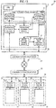
- the reference numeral 1 represents an elevator management system according to this embodiment.
- This elevator management system 1 is configured by including a management server 2 for managing a plurality of elevators 3.
- the management server 2 and the plurality of elevators 3 are connected via a communication path 19 such as an intranet.
- the management server 2 is a management apparatus that acquires operation data of each elevator 3 via a receiving circuit, learns the operation status of each elevator 3 from the acquired operation data, and manages the operation of each elevator 3 by outputting management information via an output circuit.
- the management server 2 is configured by including a CPU (Central Processing Unit) 4, an auxiliary storage apparatus 5, and a memory 6.
- the CPU 4 is a processor (controller) that controls the operation of the entire management server 2.
- the auxiliary storage apparatus 5 is composed of, for example, large-capacity nonvolatile storage devices such as hard disk drives and SSDs (Solid State Drives) and is used to store programs and data for a long period of time. Some of storage areas provided by this auxiliary storage apparatus 5 are used as an operation data table TB10 and a learning data table TB20 described later.
- the memory 6 is composed of, for example, a volatile semiconductor memory, is also used as a work memory for the CPU 4, and includes an operation storage module 7, an operation learning module 8, a route determination module 9, and a route instruction module 10. Incidentally, the memory 6 may accumulate and record the operation data as appropriate.
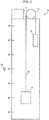
- Each elevator 3 operates to lift and lower a cage 12 in a hoistway installed in a building between boarding places provided respectively at floor levels of, for example, a first floor to a seventh floor as illustrated in Fig. 2 .
- This cage 12 is attached to one end side of a primary rope 13, to the other end side of which a counterbalancing weight 14 is attached. Furthermore, the primary rope 13 is wound around a hoist 15.
- the hoist 15 is a hoisting mechanism for driving the cage 12 to lift and lower it and is installed together with a control apparatus for controlling hoisting operation of the cage 12 (hereinafter referred to as an elevator control apparatus) 11 in a machine room provided above the hoistway.
- the elevator control apparatus 11 ( Fig. 1 ) is a computer apparatus for controlling the operation of the cage 12 and controls the hoist 15 to lift and lower the cage 12 in response to a passenger's operation (cage call information) of a call button 16 ( Fig. 2 ) provided at a boarding place.
- the elevator 3 is inefficient because it is difficult for the elevator 3 to judge in which time slot and through which route the cage 12 does not have to operate; however, the elevator 3 is normally operated in such a manner that the cage 12 can be operated from the highest floor to the lowest floor.
- the elevator management system 1 is equipped with a learning function in order to make the above-described judgment.
- the learning function mounted in the management server 2 of the elevator management system 1 will be explained.
- the learning function performs, for example, deep learning.
- the learning function of the elevator management system 1 learns an operation tendency by predicting the operation status of the call button 16 and a destination floor designating button of each cage 12 a specified amount of time later (for example, 5 minutes later as a cycle for the cage 12 to make one run along a traveling route) after accepting the cage call information of each floor level and/or the operation of the destination floor designating button of each cage 12 (destination floor designating information).
- Fig. 3 illustrates an example of the learning function. Arithmetic operation are performed by applying weighting to between neurons (circles in Fig. 3 ) in adjacent layers (columns in Fig. 3 ). Regarding this learning function, after an array of as many dimensions as the number of inputs to the call button 16 of each floor level and the destination floor designating button of each cage 12 is input, the management server 2 performs specified arithmetic operations in a plurality of hidden layers and an output layer. Incidentally, there is one input layer for a floor level where the input is performed; and there is one output layer for a floor level where the output is performed. Also, a plurality of hidden layers exist between the input layer and the output layer.
- the management server 2 outputs an array of as many dimensions as the number of inputs to the call button 16 at each floor level and the destination floor designating button of each cage 12.
- a specified arithmetic operation(s) in the hidden layers is, for example, an arithmetic operation(s) using activation functions such as a Sigmoid function, a hyperbolic tangent function, and a ramp function.
- a specified arithmetic operation(s) in the output layer is, for example, an arithmetic operation(s) using a Softmax function and so on.
- the management server 2 predicts how the cage 12 will be called in the next cycle, according to this learning function.
- the management server 2 predicts that the cage 12 moving up will be called at the 2 nd floor and the cage 12 moving down will be called at the 4 th floor in the next cycle.
- ⁇ represents a case where the button is pressed; and “ ⁇ ” represents a case where the button is not pressed. Furthermore, regarding each floor level, “ ⁇ ” represents a button when calling the cage 12 moving up at the boarding place; “ ⁇ ” represents a button when calling the cage 12 moving down at the boarding place; and “ ⁇ ” represents a button when a passenger is getting off from the cage 12 at the relevant floor.
- Fig. 3 illustrates an example of the case where there is only one cage 12, there is one row of " ⁇ " for each floor; however, there may be a plurality of cages 12.
- the management server 2 predicts, by means of deep learning, that the cage 12 will not be called from the 4 th floor to the 7 th floor during a period of time required for the cage 12 to make one run along the route.
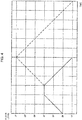
- the management server 2 issues an instruction to the elevator control apparatus 11 to operate the cage 12 along an operation route with the 4 th floor as a destination floor as indicated with a solid line in Fig. 4 .
- the management server 2 issues an instruction to the elevator control apparatus 11 to invert a traveling direction of the cage 12 after waiting time for a passenger(s) to get on and/or off the cage 12 at the 4 th floor.
- a broken line in Fig. 4 indicates a conventional operation route and the cage reaches to the 7 th floor which is the highest floor according to the conventional operation.
- the memory 6 of the management server 2 stores the operation storage module 7, the operation learning module 8, the route determination module 9, and the route instruction module 10 and the auxiliary storage apparatus 5 of the management server 2 stores the operation data table TB10 and the learning data table TB20.
- the operation storage module 7 is a program having a function that acquires the operation data from the elevator control apparatus 11 of each elevator 3, for example, every day and stores the acquired operation data in the operation data table TB10.
- the operation learning module 8 is a program that performs learning as illustrated in Fig. 3 on the basis of the operation data acquired from the operation data table TB10, for example, for one year every year and changes, for example, necessary values for learning such as a weight value as illustrated in Fig. 3 . Furthermore, the operation learning module 8 records the status of the call button 16 at each floor level and the status of the destination floor designating button of each cage 12 which are calculated as a learning result (the learning result) in the learning data table TB20. Incidentally, the learning result is calculated for each combination of the status of the call button 16 at each arbitrary floor level and the status of the destination floor designating button of each cage 12.
- the route determination module 9 is a program that acquires the learning result from the learning data table TB20 and determines the operation route of the cage 12.
- the route determination module 9 derives a route which can be omitted and along which the cage 12 does not have to be operated, from each learning result and determines a route which does not pass through the above-mentioned route, as a shortened route, to be the operation route of the cage 12.
- the route determination module 9 recognizes that it is unnecessary to pass through the 2 nd floor to the 7 th floor regarding either the input row or the output row.
- the route determination module 9 determines the shortened route, which does not pass through the 2nd floor to the 7th floor, as the operation route of the cage 12. Incidentally, if there is no route which can be omitted, the route determination module 9 determines the normal route along which the cage 12 moves between the lowest floor and the highest floor, as the operation route of the cage 12.
- the route instruction module 10 is a program that corrects the operation route determined by the route determination module 9 according to the position, traveling direction, etc. of each cage which are given from the elevator control apparatus 11 of each elevator 3. For example, when the call button 16 is pressed within the operation route where the cage 12 has not passed through yet during the operation of the cage 12, or when something which has not occurred yet is predicted while the door for the cage 12 is open, the operation route of the cage 12 is corrected and this corrected operation route is transmitted as the management information to the elevator control apparatus 11 of the elevator 3.
- the route instruction module 10 transmits the operation route determined by the route determination module 9, without any change, to the elevator control apparatus 11 of the elevator 3. Furthermore, the route instruction module 10 determines one or more cages 12 to be operated from among the plurality of cages 12 according to the operation route determined by the route determination module 9.
- the operation data table TB10 stores, as illustrated in Fig. 5 , the status of the call button 16 at each floor level (the cage call information) and the status of the destination floor designating button of each cage 12 (the destination floor designating information) as the operation data every 5 minutes (time required to make one run along the route).
- " ⁇ ", “ ⁇ ", “ ⁇ ”, “ ⁇ ”, and “ ⁇ ” in Fig. 5 have the same meanings as those in Fig. 3 .
- the learning data table TB20 stores, as illustrated in Fig. 6 , the status of the call button 16 at each arbitrary floor level and the status of the destination floor designating button of each cage 12 as inputs and the status of the call button 16 at each floor level and the status of the destination floor designating button of each cage 12 five minutes later (time required to make one run along the route) as outputs.
- " ⁇ ", “ ⁇ ”, “ ⁇ ”, “ ⁇ ”, and “ ⁇ ” in Fig. 6 have the same meanings as those in Fig. 3 .
- Fig. 7 illustrates a processing sequence for operation data acquisition processing executed by the operation storage module 7.
- the operation storage module 7 acquires the operation data from the elevator control apparatus 11 of each elevator 3 according to the processing sequence illustrated in this Fig. 6 .
- the operation storage module 7 starts the operation data acquisition processing illustrated in this Fig. 7 , for example, at a set time every day.
- the operation storage module 7 firstly acquires the operation data for one day from the elevator control apparatus 11 of each elevator 3 (S11). Subsequently, the operation storage module 7 stores the operation data for one day in the operation data table TB10 (S12) and terminates the operation data acquisition processing.
- Fig. 8 illustrates a processing sequence for operation data learning processing executed by the operation learning module 8.
- the operation learning module 8 learns the status of the call button 16 at each floor level and the status of the destination floor designating button of each cage 12 five minutes later (time required to make one run along the route) (the learning result) with respect to the status of the call button 16 at each arbitrary floor level and the status of the destination floor designating button of each cage 12 in accordance with the processing sequence illustrated in this Fig. 8 based on the operation data acquired from the operation data table TB10.
- the operation learning module 8 starts the operation data learning processing, for example, at a set time of the year every year.
- the operation learning module 8 firstly acquires the operation data for one year from the operation data table TB10 and learns based on the acquired operation data (S15). Subsequently, the operation learning module 8 stores the learning result as learning data in the learning data table TB20 (S16) and terminates the operation data learning processing.
- Fig. 9 illustrates a processing sequence for operation route determination processing executed by the route determination module 9.
- the route determination module 9 determines the operation route of the cage 12 in accordance with the processing sequence illustrated in this Fig. 9 .
- the route determination module 9 starts the operation route determination processing illustrated in this Fig. 9 .
- the route determination module 9 firstly acquires the learning data from the learning data table TB20 (S21). Subsequently, the route determination module 9 judges whether or not there is any route which can be omitted, with respect to each learning result (S22). When a negative result is obtained in this judgment, the route determination module 9 transmits the normal route as the operation route to the route instruction module 10 and terminates the operation data learning processing.
- the route determination module 9 when an affirmative result is obtained in the judgment of step S22 because there is a route which can be omitted, the route determination module 9 generates a shortened route by omitting that route (S23), transmits the shortened route to the route instruction module 10, and terminates the operation data learning processing.
- Fig. 10 illustrates a processing sequence for operation instruction processing executed by the route instruction module 10.
- the route instruction module 10 designates the operation route to the cage 12 in accordance with the processing sequence illustrated in this Fig. 10 .
- the route instruction module 10 starts the operation route correction processing during operation as illustrated in this Fig. 10 .
- the route instruction module 10 firstly determines the cage 12 to be operated (S25). Subsequently, the route instruction module 10: transmits the operation route to the elevator control apparatus 11 which controls the relevant cage 12 (S26); and terminates the operation instruction processing. Then, the elevator control apparatus 11 which has received the operation route operates the cage 12 in accordance with this operation route.
- Fig. 11 illustrates a processing sequence for operation route correction processing during operation, which is executed by the route instruction module 10.
- the route instruction module 10 corrects the operation route of the cage 12 in accordance with the processing sequence illustrated in this Fig. 11 .
- the route instruction module 10 starts the operation route correction processing during operation as illustrated in this Fig. 11 .
- the route instruction module 10 firstly acquires the position and traveling direction of the cage 12 from each elevator control apparatus 11 and judges whether there is any cage 12 approaching to the relevant boarding place or not (S31). When an affirmative result is obtained in this judgment because there is a cage 12 approaching to that boarding place, the route instruction module 10 terminates the operation route correction processing during operation. Since this approaching cage 12 stops at the relevant boarding place, the control by the management server 2 becomes no longer necessary.
- the route instruction module 10 selects a cage 12 closest to the boarding place (S32). Subsequently, the route instruction module 10: transmits an instruction to the elevator control apparatus 11, which controls the selected cage 12, to invert the traveling direction of the relevant cage 12 (S33); and terminates the operation route correction processing during operation.
- Fig. 12 illustrates a processing sequence for operation route correction processing executed by the route instruction module 10 while the door is open.
- the route instruction module 10 corrects the operation route of the cage 12 in accordance with the processing sequence illustrated in this Fig. 12 .
- the route instruction module 10 starts the operation route correction processing while the door is open as illustrated in this Fig. 12 .
- the route instruction module 10 firstly judges whether or not time elapsed from the time when the button pressing operation should have occurred to this door-opened time is equal to or less than a specified value (S41). When the specified amount of time has passed and the route instruction module 10 judges that an error in the prediction based on the learning result cannot be corrected, and when a negative result is thereby obtained in this judgment, the route instruction module 10 terminates the operation route correction processing while the door is open.
- the route instruction module 10 judges that the error in the prediction based on the learning result can be corrected, and when an affirmative result is thereby obtained in the judgment of step S41, the route instruction module 10: transmits an instruction to the elevator control apparatus 11, which controls this cage 12, to extend the time to open the door (S42); and then terminates the operation route correction processing while the door is open.
- the management server 2 issues the instruction to each elevator 3 to operate by omitting any route which can be omitted, by predicting, based on the learning data, how each elevator will operate in the next cycle.
- this elevator management system 1 makes it possible to apply the operation according to the status of use to the cage(s) 12 without any alterations or the like of programs and the cage(s) 12 can be operated efficiently.
- the aforementioned embodiment has described the case where the elevator management system 1 to which the present invention is applied is configured as illustrated in Fig. 1 ; however, the present invention is not limited to this example and a wide variety of other configurations can be applied as the configurations of these elevator management systems.
- an elevator management system 20 may be configured to connect the management server 2 with each elevator 3 via a communication network 21 such as the Internet.
- the management server 2 is a cloud server or a server apparatus installed at a data center.
- the management server 2 is connected to the elevators 3 via the communication network 21, communication equipment 22, 23 such as a switching hub and a router, and a communication path 24 such as an intranet.
- the elevator management system 20 can apply the present invention even in such a case by employing the configuration as illustrated in Fig. 13 .
- the elevator management system 20 is installed at, for example, another building operated with the same working hours or business hours by being connected to the outside via, for example, the Internet and can acquire the operation data of the elevators 3 which operate in similar manners. Accordingly, the elevator management system 20 can acquire many pieces of operation data for learning and enhance the accuracy of learning.
- the elevator management system 20 is connected to the outside via, for example, the Internet and uses weather data and operation information of public transportation facilities as information for learning, it can enhance the accuracy of learning.
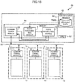
- a cloud server 35 for calculating learning data may be connected to a management server 31, which is a server apparatus, and each elevator 3 via the communication network 21 and communication equipment 37, 39 such as a switching hub and a router.
- the cloud server 35 is composed of a cloud server, a data center, and so on.
- processing mainly focused on the operation data learning processing which requires transfer of the operation data with heavy load and learning processing can be executed by the cloud server 35 with high performance; and processing mainly focused on the operation instruction processing which requires frequent communication with the elevators 3 and for which any delay in the communication would be fatal can be executed by the management server 31.
- the elevator management system 30 can reduce any influence caused by the delay in the communication and can be installed also in a relatively limited installment space.
- the acquisition of the learning data by a learning data acquisition module 34 and the operation instruction to the relevant elevator 3 can be implemented promptly by installing the management server 31 in a DMZ (demilitarized zone).
- an elevator management system 50 as illustrated in Fig. 15 , communication via the communication equipment 37 ( Fig. 14 ) such as the switching hub and the router becomes no longer necessary by providing a management server 51, which is a server apparatus, with a communication module 54. Therefore, the present invention can be applied even in a case where the switching hub, the router, and so on cannot be used due to the environment where the switching hub, the router, and so on are not installed, or due to some security reason. Incidentally, the configuration in Fig. 15 can return to the conventional operation of the elevators 3 simply by removing the management server 51.
- an auxiliary storage apparatus 63 such as an SD card in which learning data TB30 is recorded may be connected to an elevator management system 60 as illustrated in Fig. 16 .
- the auxiliary storage apparatus 63 updates the learning data TB 30 when a customer engineer who periodically performs maintenance and inspection of the elevators 3 performs carrying maintenance or performs inspection.
- the learning data TB30 is created by copying the learning data TB20.
- the configuration in Fig. 16 can return to the conventional operation of the elevators 3 simply by removing a management server 61 which is a server apparatus.
- the aforementioned embodiment has described the case where the deep learning is used as a learning means; however, the present invention is not limited to this example and a statistic means such as regression analysis may be used and machine learning other than the deep learning may be used.
- the aforementioned embodiment has described the case where the pressed state of the call button 16 at each floor level and the destination floor designating button of each cage 12 after one run along the route is predicted based only on the pressed state of the call button 16 at each floor level and the destination floor designating button of each cage 12; however, the present invention is not limited to this example and season information such as spring, summer, fall, and winter, year information such as a year when the Olympics will be held or a leap year, time slot information such as morning, noon, and night, and so on may be reflected.
- season information such as spring, summer, fall, and winter
- year information such as a year when the Olympics will be held or a leap year
- time slot information such as morning, noon, and night, and so on may be reflected.
- the aforementioned embodiment has described the case where no consideration is paid to local information within the building; however, the present invention is not limited to this example and the location information such as information about the use of meeting rooms in the building may be acquired through the communication path 19 and be reflected in the prediction result.
Landscapes
- Engineering & Computer Science (AREA)
- Automation & Control Theory (AREA)
- Elevator Control (AREA)
Abstract
Description
- The present invention relates to an elevator management system and an elevator management method and relates to, for example, an elevator management system for managing a plurality of cages, which operate between a plurality of floors, as a group.
- Conventionally, this type of elevator management system moves cages between the lowest floor and the highest floor so that the distances between the plurality of cages in a gravity direction become equal. However, when some cages are delayed as many passengers get into and out of the cages, the plurality of cages cannot be operated uniformly and this may result in the occurrence of situations, for example, where the plurality of cages stop at the same floor at the same timing and waiting time at other floors become long.
- So, PTL 1 proposes an invention for controlling an elevator management system so that cage waiting time at each floor becomes uniform in order to enhance cage operation efficiency. While this invention is premised on repetitive operation of each of the plurality of cages between the lowest floor and the highest floor, the invention is designed so that the positions and moving directions of the cages after a specified amount of time are set and the cages are operated in accordance with the set positions and moving directions.
- PTL 1: Japanese Patent No.
4139819 - The problem of the conventional elevator management system is that the operation of the cages may become wasteful. Therefore, the present invention aims at proposing an elevator management system and elevator management method for efficiently operating the cages.
- In order to solve the above-described problem, the present invention provides an elevator management system for managing an elevator equipped with a control apparatus for operating a cage(s) across a plurality of floors, wherein the elevator management system includes a management apparatus for managing the control apparatus; wherein the management apparatus includes: a receiving circuit that receives destination floor designating information and cage call information; a memory that accumulates and records the information received by the receiving circuit; a controller that learns an operation tendency of the cages based on the information recorded in the memory; an output circuit that outputs management information to the control apparatus; wherein the controller: predicts the destination floor designating information and the cage call information a specified amount of time later from the information received by the receiving circuit on the basis of a result of the learning; and forms the management information on the basis of a result of the prediction of the specified amount of time later so as to limit a range of operation floors of the cages; and wherein the control apparatus controls operation of the cages on the basis of the management information.
- Furthermore, the present invention provides an elevator management method for managing a control apparatus for operating a cage or cages of an elevator across a plurality of floors by using a management apparatus, wherein the management apparatus: receives destination floor designating information and cage call information; accumulates and records the information received by a receiving circuit; learns an operation tendency of the cages based on the received information; outputs management information as a learning result to the control apparatus; predicts the destination floor designating information and the cage call information a specified amount of time later from the received information on the basis of the learning result; forms the management information on the basis of a result of the prediction so as to limit a range of operation floors of the cages; and causes the control apparatus to control operation of the cages on the basis of the management information.
- The elevator management system and the elevator management method for operating the cages efficiently can be implemented according to the present invention.
-
-
Fig. 1 is a block diagram illustrating the configuration of an elevator management system according to this embodiment; -
Fig. 2 is a schematic diagram illustrating a main part of a schematic structure of an elevator apparatus according to this embodiment; -
Fig. 3 is a diagram illustrating operation routes for the elevator apparatus according to this embodiment; -
Fig. 4 is a conceptual diagram for explaining learning according to this embodiment; -
Fig. 5 is a conceptual diagram illustrating the configuration of an operation data table according to this embodiment; -
Fig. 6 is a conceptual diagram illustrating the configuration of a learning data table according to this embodiment; -
Fig. 7 is a flowchart illustrating a processing sequence for operation data storage processing; -
Fig. 8 is a flowchart illustrating a processing sequence for operation data learning processing; -
Fig. 9 is a flowchart illustrating a processing sequence for operation route determination processing; -
Fig. 10 is a flowchart illustrating a processing sequence for operation instruction processing; -
Fig. 11 is a flowchart illustrating a processing sequence for operation route correction processing during operation; -
Fig. 12 is a flowchart illustrating a processing sequence for operation route correction processing while a door is open; -
Fig. 13 is a block diagram illustrating the configuration of an elevator management system according to another embodiment; -
Fig. 14 is a block diagram illustrating the configuration of an elevator management system according to another embodiment; -
Fig. 15 is a block diagram illustrating the configuration of an elevator management system according to another embodiment; and -
Fig. 16 is a block diagram illustrating the configuration of an elevator management system according to another embodiment. - (1) Configuration of Elevator Management System According to This Embodiment Referring to
Fig. 1 , thereference numeral 1 represents an elevator management system according to this embodiment. Thiselevator management system 1 is configured by including amanagement server 2 for managing a plurality ofelevators 3. Themanagement server 2 and the plurality ofelevators 3 are connected via acommunication path 19 such as an intranet. - The
management server 2 is a management apparatus that acquires operation data of eachelevator 3 via a receiving circuit, learns the operation status of eachelevator 3 from the acquired operation data, and manages the operation of eachelevator 3 by outputting management information via an output circuit. Themanagement server 2 is configured by including a CPU (Central Processing Unit) 4, anauxiliary storage apparatus 5, and amemory 6. - The CPU 4 is a processor (controller) that controls the operation of the
entire management server 2. Theauxiliary storage apparatus 5 is composed of, for example, large-capacity nonvolatile storage devices such as hard disk drives and SSDs (Solid State Drives) and is used to store programs and data for a long period of time. Some of storage areas provided by thisauxiliary storage apparatus 5 are used as an operation data table TB10 and a learning data table TB20 described later. - The
memory 6 is composed of, for example, a volatile semiconductor memory, is also used as a work memory for the CPU 4, and includes anoperation storage module 7, anoperation learning module 8, aroute determination module 9, and aroute instruction module 10. Incidentally, thememory 6 may accumulate and record the operation data as appropriate. - Each
elevator 3 operates to lift and lower acage 12 in a hoistway installed in a building between boarding places provided respectively at floor levels of, for example, a first floor to a seventh floor as illustrated inFig. 2 . - This
cage 12 is attached to one end side of aprimary rope 13, to the other end side of which a counterbalancingweight 14 is attached. Furthermore, theprimary rope 13 is wound around ahoist 15. Thehoist 15 is a hoisting mechanism for driving thecage 12 to lift and lower it and is installed together with a control apparatus for controlling hoisting operation of the cage 12 (hereinafter referred to as an elevator control apparatus) 11 in a machine room provided above the hoistway. - The elevator control apparatus 11 (
Fig. 1 ) is a computer apparatus for controlling the operation of thecage 12 and controls thehoist 15 to lift and lower thecage 12 in response to a passenger's operation (cage call information) of a call button 16 (Fig. 2 ) provided at a boarding place. - The
elevator 3 is inefficient because it is difficult for theelevator 3 to judge in which time slot and through which route thecage 12 does not have to operate; however, theelevator 3 is normally operated in such a manner that thecage 12 can be operated from the highest floor to the lowest floor. According to the present invention, theelevator management system 1 is equipped with a learning function in order to make the above-described judgment. - Next, the learning function mounted in the
management server 2 of theelevator management system 1 will be explained. Incidentally, the learning function performs, for example, deep learning. - The learning function of the
elevator management system 1 learns an operation tendency by predicting the operation status of thecall button 16 and a destination floor designating button of each cage 12 a specified amount of time later (for example, 5 minutes later as a cycle for thecage 12 to make one run along a traveling route) after accepting the cage call information of each floor level and/or the operation of the destination floor designating button of each cage 12 (destination floor designating information). -
Fig. 3 illustrates an example of the learning function. Arithmetic operation are performed by applying weighting to between neurons (circles inFig. 3 ) in adjacent layers (columns inFig. 3 ). Regarding this learning function, after an array of as many dimensions as the number of inputs to thecall button 16 of each floor level and the destination floor designating button of eachcage 12 is input, themanagement server 2 performs specified arithmetic operations in a plurality of hidden layers and an output layer. Incidentally, there is one input layer for a floor level where the input is performed; and there is one output layer for a floor level where the output is performed. Also, a plurality of hidden layers exist between the input layer and the output layer. - Then, as a result of the arithmetic operations, the
management server 2 outputs an array of as many dimensions as the number of inputs to thecall button 16 at each floor level and the destination floor designating button of eachcage 12. Incidentally, a specified arithmetic operation(s) in the hidden layers is, for example, an arithmetic operation(s) using activation functions such as a Sigmoid function, a hyperbolic tangent function, and a ramp function. Furthermore, a specified arithmetic operation(s) in the output layer is, for example, an arithmetic operation(s) using a Softmax function and so on. - Referring to
Fig. 3 , when thecage 12 moving up is called at the 1st floor and thecage 12 moving up and thecage 12 moving down are called at the 2nd floor, themanagement server 2 predicts how thecage 12 will be called in the next cycle, according to this learning function. - In this case, the
management server 2 predicts that thecage 12 moving up will be called at the 2nd floor and thecage 12 moving down will be called at the 4th floor in the next cycle. - Incidentally, referring to
Fig. 3 , "○" represents a case where the button is pressed; and "×" represents a case where the button is not pressed. Furthermore, regarding each floor level, "↑" represents a button when calling thecage 12 moving up at the boarding place; "↓" represents a button when calling thecage 12 moving down at the boarding place; and "→" represents a button when a passenger is getting off from thecage 12 at the relevant floor. Incidentally, sinceFig. 3 illustrates an example of the case where there is only onecage 12, there is one row of "→" for each floor; however, there may be a plurality ofcages 12. - In the case of the prediction in
Fig. 3 , themanagement server 2 predicts, by means of deep learning, that thecage 12 will not be called from the 4th floor to the 7th floor during a period of time required for thecage 12 to make one run along the route. Themanagement server 2 issues an instruction to theelevator control apparatus 11 to operate thecage 12 along an operation route with the 4th floor as a destination floor as indicated with a solid line inFig. 4 . Specifically speaking, themanagement server 2 issues an instruction to theelevator control apparatus 11 to invert a traveling direction of thecage 12 after waiting time for a passenger(s) to get on and/or off thecage 12 at the 4th floor. Incidentally, a broken line inFig. 4 indicates a conventional operation route and the cage reaches to the 7th floor which is the highest floor according to the conventional operation. - As means for implementing the above-described learning function, as illustrated in
Fig. 1 , thememory 6 of themanagement server 2 stores theoperation storage module 7, theoperation learning module 8, theroute determination module 9, and theroute instruction module 10 and theauxiliary storage apparatus 5 of themanagement server 2 stores the operation data table TB10 and the learning data table TB20. - The
operation storage module 7 is a program having a function that acquires the operation data from theelevator control apparatus 11 of eachelevator 3, for example, every day and stores the acquired operation data in the operation data table TB10. - The
operation learning module 8 is a program that performs learning as illustrated inFig. 3 on the basis of the operation data acquired from the operation data table TB10, for example, for one year every year and changes, for example, necessary values for learning such as a weight value as illustrated inFig. 3 . Furthermore, theoperation learning module 8 records the status of thecall button 16 at each floor level and the status of the destination floor designating button of eachcage 12 which are calculated as a learning result (the learning result) in the learning data table TB20. Incidentally, the learning result is calculated for each combination of the status of thecall button 16 at each arbitrary floor level and the status of the destination floor designating button of eachcage 12. - The
route determination module 9 is a program that acquires the learning result from the learning data table TB20 and determines the operation route of thecage 12. Theroute determination module 9 derives a route which can be omitted and along which thecage 12 does not have to be operated, from each learning result and determines a route which does not pass through the above-mentioned route, as a shortened route, to be the operation route of thecage 12. - For example, in a case of the learning result as illustrated in an input row and an output row in
Fig. 6 , theroute determination module 9 recognizes that it is unnecessary to pass through the 2nd floor to the 7th floor regarding either the input row or the output row. - Accordingly, the
route determination module 9 determines the shortened route, which does not pass through the 2nd floor to the 7th floor, as the operation route of thecage 12. Incidentally, if there is no route which can be omitted, theroute determination module 9 determines the normal route along which thecage 12 moves between the lowest floor and the highest floor, as the operation route of thecage 12. - The
route instruction module 10 is a program that corrects the operation route determined by theroute determination module 9 according to the position, traveling direction, etc. of each cage which are given from theelevator control apparatus 11 of eachelevator 3. For example, when thecall button 16 is pressed within the operation route where thecage 12 has not passed through yet during the operation of thecage 12, or when something which has not occurred yet is predicted while the door for thecage 12 is open, the operation route of thecage 12 is corrected and this corrected operation route is transmitted as the management information to theelevator control apparatus 11 of theelevator 3. - Incidentally, when the operation route of the
cage 12 does not have to be corrected, theroute instruction module 10 transmits the operation route determined by theroute determination module 9, without any change, to theelevator control apparatus 11 of theelevator 3. Furthermore, theroute instruction module 10 determines one ormore cages 12 to be operated from among the plurality ofcages 12 according to the operation route determined by theroute determination module 9. - The operation data table TB10 stores, as illustrated in
Fig. 5 , the status of thecall button 16 at each floor level (the cage call information) and the status of the destination floor designating button of each cage 12 (the destination floor designating information) as the operation data every 5 minutes (time required to make one run along the route). Incidentally, "○", "×", "↑", "↓", and "→" inFig. 5 have the same meanings as those inFig. 3 . - Similarly, the learning data table TB20 stores, as illustrated in
Fig. 6 , the status of thecall button 16 at each arbitrary floor level and the status of the destination floor designating button of eachcage 12 as inputs and the status of thecall button 16 at each floor level and the status of the destination floor designating button of eachcage 12 five minutes later (time required to make one run along the route) as outputs. Incidentally, "○", "×", "↑", "↓", and "→" inFig. 6 have the same meanings as those inFig. 3 . - Next, various kinds of processing executed by the above-described
management server 2 will be explained. Incidentally, a processing subject of the various kinds of processing will be hereinafter explained as a "program"; however, it is needless to say that practically the CPU 4 executes the processing based on the "program." -
Fig. 7 illustrates a processing sequence for operation data acquisition processing executed by theoperation storage module 7. Theoperation storage module 7 acquires the operation data from theelevator control apparatus 11 of eachelevator 3 according to the processing sequence illustrated in thisFig. 6 . - Practically, the
operation storage module 7 starts the operation data acquisition processing illustrated in thisFig. 7 , for example, at a set time every day. - Then, the
operation storage module 7 firstly acquires the operation data for one day from theelevator control apparatus 11 of each elevator 3 (S11). Subsequently, theoperation storage module 7 stores the operation data for one day in the operation data table TB10 (S12) and terminates the operation data acquisition processing. -
Fig. 8 illustrates a processing sequence for operation data learning processing executed by theoperation learning module 8. Theoperation learning module 8 learns the status of thecall button 16 at each floor level and the status of the destination floor designating button of eachcage 12 five minutes later (time required to make one run along the route) (the learning result) with respect to the status of thecall button 16 at each arbitrary floor level and the status of the destination floor designating button of eachcage 12 in accordance with the processing sequence illustrated in thisFig. 8 based on the operation data acquired from the operation data table TB10. - Practically, the
operation learning module 8 starts the operation data learning processing, for example, at a set time of the year every year. - Then, the
operation learning module 8 firstly acquires the operation data for one year from the operation data table TB10 and learns based on the acquired operation data (S15). Subsequently, theoperation learning module 8 stores the learning result as learning data in the learning data table TB20 (S16) and terminates the operation data learning processing. -
Fig. 9 illustrates a processing sequence for operation route determination processing executed by theroute determination module 9. Theroute determination module 9 determines the operation route of thecage 12 in accordance with the processing sequence illustrated in thisFig. 9 . - Practically, after the operation data learning processing terminates, the
route determination module 9 starts the operation route determination processing illustrated in thisFig. 9 . - Then, the
route determination module 9 firstly acquires the learning data from the learning data table TB20 (S21). Subsequently, theroute determination module 9 judges whether or not there is any route which can be omitted, with respect to each learning result (S22). When a negative result is obtained in this judgment, theroute determination module 9 transmits the normal route as the operation route to theroute instruction module 10 and terminates the operation data learning processing. - On the other hand, when an affirmative result is obtained in the judgment of step S22 because there is a route which can be omitted, the
route determination module 9 generates a shortened route by omitting that route (S23), transmits the shortened route to theroute instruction module 10, and terminates the operation data learning processing. -
Fig. 10 illustrates a processing sequence for operation instruction processing executed by theroute instruction module 10. Theroute instruction module 10 designates the operation route to thecage 12 in accordance with the processing sequence illustrated in thisFig. 10 . - Practically, after receiving the passenger's operation on the
call button 16 from theelevator control apparatus 11 of theelevator 3, theroute instruction module 10 starts the operation route correction processing during operation as illustrated in thisFig. 10 . - Then, the
route instruction module 10 firstly determines thecage 12 to be operated (S25). Subsequently, the route instruction module 10: transmits the operation route to theelevator control apparatus 11 which controls the relevant cage 12 (S26); and terminates the operation instruction processing. Then, theelevator control apparatus 11 which has received the operation route operates thecage 12 in accordance with this operation route. -
Fig. 11 illustrates a processing sequence for operation route correction processing during operation, which is executed by theroute instruction module 10. Theroute instruction module 10 corrects the operation route of thecage 12 in accordance with the processing sequence illustrated in thisFig. 11 . - Practically, after the operation instruction processing terminates and the
route instruction module 10 receives the passenger's operation on thecall button 16 at a boarding place within the operation route of thecage 12, whose operation is designated by this operation instruction processing, from theelevator control apparatus 11, theroute instruction module 10 starts the operation route correction processing during operation as illustrated in thisFig. 11 . - Then, the
route instruction module 10 firstly acquires the position and traveling direction of thecage 12 from eachelevator control apparatus 11 and judges whether there is anycage 12 approaching to the relevant boarding place or not (S31). When an affirmative result is obtained in this judgment because there is acage 12 approaching to that boarding place, theroute instruction module 10 terminates the operation route correction processing during operation. Since this approachingcage 12 stops at the relevant boarding place, the control by themanagement server 2 becomes no longer necessary. - On the other hand, when a negative result is obtained in the judgment of step S31 because there is no
cage 12 approaching, theroute instruction module 10 selects acage 12 closest to the boarding place (S32). Subsequently, the route instruction module 10: transmits an instruction to theelevator control apparatus 11, which controls the selectedcage 12, to invert the traveling direction of the relevant cage 12 (S33); and terminates the operation route correction processing during operation. -
Fig. 12 illustrates a processing sequence for operation route correction processing executed by theroute instruction module 10 while the door is open. Theroute instruction module 10 corrects the operation route of thecage 12 in accordance with the processing sequence illustrated in thisFig. 12 . - Practically, after the operation instruction processing terminates and the
route instruction module 10 receives a button pressing operation, which has not occurred yet with respect to the cage 12 (and which should have occurred according to the prediction based on the learning result), from theelevator control apparatus 11 while the door of thecage 12 which has been designated to operate according to this operation instruction processing is opened (hereinafter referred to as door-opened time), theroute instruction module 10 starts the operation route correction processing while the door is open as illustrated in thisFig. 12 . - Then, the
route instruction module 10 firstly judges whether or not time elapsed from the time when the button pressing operation should have occurred to this door-opened time is equal to or less than a specified value (S41). When the specified amount of time has passed and theroute instruction module 10 judges that an error in the prediction based on the learning result cannot be corrected, and when a negative result is thereby obtained in this judgment, theroute instruction module 10 terminates the operation route correction processing while the door is open. - On the other hand, when the specified amount of time has not passed and the
route instruction module 10 judges that the error in the prediction based on the learning result can be corrected, and when an affirmative result is thereby obtained in the judgment of step S41, the route instruction module 10: transmits an instruction to theelevator control apparatus 11, which controls thiscage 12, to extend the time to open the door (S42); and then terminates the operation route correction processing while the door is open. - With the
elevator management system 1 according to this embodiment as described above, themanagement server 2 issues the instruction to eachelevator 3 to operate by omitting any route which can be omitted, by predicting, based on the learning data, how each elevator will operate in the next cycle. - Therefore, this
elevator management system 1 makes it possible to apply the operation according to the status of use to the cage(s) 12 without any alterations or the like of programs and the cage(s) 12 can be operated efficiently. - Incidentally, the aforementioned embodiment has described the case where the
elevator management system 1 to which the present invention is applied is configured as illustrated inFig. 1 ; however, the present invention is not limited to this example and a wide variety of other configurations can be applied as the configurations of these elevator management systems. - For example, as illustrated in
Fig. 13 , anelevator management system 20 may be configured to connect themanagement server 2 with eachelevator 3 via acommunication network 21 such as the Internet. In this case, themanagement server 2 is a cloud server or a server apparatus installed at a data center. Themanagement server 2 is connected to theelevators 3 via thecommunication network 21,communication equipment communication path 24 such as an intranet. - In the case of the configuration as illustrated in
Fig. 1 , an inside space of the hoistway of theelevators 3 or a machine room is assumed as a place to install themanagement server 2, but it is sometimes difficult to install large-capacity data storage devices capable of saving the operation data for one year and the server apparatus for implementing the deep learning at such a place. However, theelevator management system 20 can apply the present invention even in such a case by employing the configuration as illustrated inFig. 13 . - Furthermore, the
elevator management system 20 is installed at, for example, another building operated with the same working hours or business hours by being connected to the outside via, for example, the Internet and can acquire the operation data of theelevators 3 which operate in similar manners. Accordingly, theelevator management system 20 can acquire many pieces of operation data for learning and enhance the accuracy of learning. - Furthermore, as the
elevator management system 20 is connected to the outside via, for example, the Internet and uses weather data and operation information of public transportation facilities as information for learning, it can enhance the accuracy of learning. - Furthermore, regarding an
elevator management system 30 as illustrated inFig. 14 , acloud server 35 for calculating learning data may be connected to amanagement server 31, which is a server apparatus, and eachelevator 3 via thecommunication network 21 andcommunication equipment cloud server 35 is composed of a cloud server, a data center, and so on. - As a result of employing the configuration illustrated in
Fig. 14 , processing mainly focused on the operation data learning processing which requires transfer of the operation data with heavy load and learning processing can be executed by thecloud server 35 with high performance; and processing mainly focused on the operation instruction processing which requires frequent communication with theelevators 3 and for which any delay in the communication would be fatal can be executed by themanagement server 31. - Accordingly, the
elevator management system 30 can reduce any influence caused by the delay in the communication and can be installed also in a relatively limited installment space. Incidentally, the acquisition of the learning data by a learningdata acquisition module 34 and the operation instruction to therelevant elevator 3 can be implemented promptly by installing themanagement server 31 in a DMZ (demilitarized zone). - Furthermore, regarding an
elevator management system 50 as illustrated inFig. 15 , communication via the communication equipment 37 (Fig. 14 ) such as the switching hub and the router becomes no longer necessary by providing amanagement server 51, which is a server apparatus, with acommunication module 54. Therefore, the present invention can be applied even in a case where the switching hub, the router, and so on cannot be used due to the environment where the switching hub, the router, and so on are not installed, or due to some security reason. Incidentally, the configuration inFig. 15 can return to the conventional operation of theelevators 3 simply by removing themanagement server 51. - Furthermore, when it is difficult to download the learning data via the communication network, an
auxiliary storage apparatus 63 such as an SD card in which learning data TB30 is recorded may be connected to anelevator management system 60 as illustrated inFig. 16 . Theauxiliary storage apparatus 63 updates the learningdata TB 30 when a customer engineer who periodically performs maintenance and inspection of theelevators 3 performs carrying maintenance or performs inspection. The learning data TB30 is created by copying the learning data TB20. Incidentally, the configuration inFig. 16 can return to the conventional operation of theelevators 3 simply by removing amanagement server 61 which is a server apparatus. - Furthermore, the aforementioned embodiment has described the case where the deep learning is used as a learning means; however, the present invention is not limited to this example and a statistic means such as regression analysis may be used and machine learning other than the deep learning may be used.
- Furthermore, the aforementioned embodiment has described the case where the pressed state of the
call button 16 at each floor level and the destination floor designating button of eachcage 12 after one run along the route is predicted based only on the pressed state of thecall button 16 at each floor level and the destination floor designating button of eachcage 12; however, the present invention is not limited to this example and season information such as spring, summer, fall, and winter, year information such as a year when the Olympics will be held or a leap year, time slot information such as morning, noon, and night, and so on may be reflected. - Furthermore, the aforementioned embodiment has described the case where no consideration is paid to local information within the building; however, the present invention is not limited to this example and the location information such as information about the use of meeting rooms in the building may be acquired through the
communication path 19 and be reflected in the prediction result. -
- 1, 20, 30, 50, 60:
- elevator management system
- 2, 31, 51, 61:
- management server
- 3:
- elevator
- 4, 32, 52, 62:
- CPU
- 5, 63:
- auxiliary storage apparatus
- 6, 33, 36, 53, 64:
- memory
- 7:
- operation storage module
- 8:
- operation learning module
- 9:
- route determination module
- 10:
- route instruction module
- 11:
- elevator control apparatus
- 12:
- cage
- 13:
- primary rope
- 14:
- counterbalancing weight
- 15:
- hoist
- 16:
- call button
- 19, 24, 38, 40:
- communication path
- 21:
- communication network
- 22, 23, 37, 39:
- communication equipment
- 35:
- cloud server
Claims (7)
- An elevator management system for managing an elevator equipped with a control apparatus for operating a cage across a plurality of floors,
the elevator management system comprising a management apparatus for managing the control apparatus,
wherein the management apparatus includes:a receiving circuit that receives destination floor designating information and cage call information;a memory that accumulates and records the information received by the receiving circuit;a controller that learns an operation tendency of the cages based on the information recorded in the memory; andan output circuit that outputs management information to the control apparatus; wherein the controller:predicts the destination floor designating information and the cage call information a specified amount of time later from the information received by the receiving circuit on the basis of a result of the learning; andforms the management information on the basis of a result of the prediction of the specified amount of time later so as to limit a range of operation floors of the cages; andwherein the control apparatus controls operation of the cages on the basis of the management information. - The elevator management system according to claim 1,
wherein the control apparatus determines a floor to be reached on the basis of the prediction of the cage call information and the destination floor designating information and inverts a traveling direction of the cage upon reaching the determined floor. - The elevator management system according to claim 1,
wherein an operation route of each of the cages is determined by predicting the cage call information and the destination floor designating information about each of the cages until an amount of time required for one operation of each of the cages elapses from a present point in time. - The elevator management system according to claim 1,
wherein when a cage call or destination floor designation which is not predicted occurs after the prediction of the cage call information and the destination floor designating information, an operation route is modified based on a current position of the cage and a current moving direction of the cage. - The elevator management system according to claim 1,
wherein door opening time of the cage is adjusted on the basis of a difference between occurrence time of a cage call and destination floor designation based on the prediction of the cage call information and the destination floor designating information and occurrence time of the cage call and the destination floor designation. - An elevator management system for managing an elevator, comprising:a first server apparatus that records an operation status of each of cages including destination floor designating information of each cage and cage call information given from each floor and learns the operation status; anda second server apparatus that predicts the cage call given from each floor on the basis of the learning,wherein operation of each cage is controlled by a control apparatus; andwherein the control apparatus determines an operation route of each cage by excluding a floor regarding which it is predicted based on the prediction of the cage call by the second server apparatus that the cage call will not occur.
- An elevator management method for managing a control apparatus for operating a cage or cages of an elevator across a plurality of floors by using a management apparatus,
wherein the management apparatus:receives destination floor designating information and cage call information;accumulates and records the received information;learns an operation tendency of the cages based on the received information;outputs management information as a learning result to the control apparatus;predicts the destination floor designating information and the cage call information a specified amount of time later from the received information on the basis of the learning result;forms the management information on the basis of a result of the prediction so as to limit a range of operation floors of the cages; andcauses the control apparatus to control operation of the cages on the basis of the management information.
Applications Claiming Priority (2)
| Application Number | Priority Date | Filing Date | Title |
|---|---|---|---|
| JP2017058235A JP6730216B2 (en) | 2017-03-23 | 2017-03-23 | Elevator management system and elevator management method |
| PCT/JP2017/041390 WO2018173363A1 (en) | 2017-03-23 | 2017-11-17 | Elevator management system, and method for managing elevator |
Publications (3)
| Publication Number | Publication Date |
|---|---|
| EP3604190A1 true EP3604190A1 (en) | 2020-02-05 |
| EP3604190A4 EP3604190A4 (en) | 2021-05-05 |
| EP3604190B1 EP3604190B1 (en) | 2025-01-08 |
Family
ID=63584305
Family Applications (1)
| Application Number | Title | Priority Date | Filing Date |
|---|---|---|---|
| EP17901590.4A Active EP3604190B1 (en) | 2017-03-23 | 2017-11-17 | Elevator management system, and method for managing elevator |
Country Status (5)
| Country | Link |
|---|---|
| EP (1) | EP3604190B1 (en) |
| JP (1) | JP6730216B2 (en) |
| CN (1) | CN110114292B (en) |
| SG (1) | SG11201906349TA (en) |
| WO (1) | WO2018173363A1 (en) |
Cited By (1)
| Publication number | Priority date | Publication date | Assignee | Title |
|---|---|---|---|---|
| CN115367576A (en) * | 2021-05-19 | 2022-11-22 | 株式会社日立制作所 | Elevator control system and elevator control method |
Families Citing this family (2)
| Publication number | Priority date | Publication date | Assignee | Title |
|---|---|---|---|---|
| US20210406433A1 (en) * | 2018-10-31 | 2021-12-30 | Showa Denko K.K. | Thermodynamic equilibrium state prediction device, prediction method and prediction program |
| CN112573316B (en) * | 2020-12-08 | 2022-08-02 | 成都睿瞳科技有限责任公司 | Elevator trapping detection method based on computer vision |
Family Cites Families (17)
| Publication number | Priority date | Publication date | Assignee | Title |
|---|---|---|---|---|
| EP0452130A3 (en) * | 1990-04-12 | 1992-01-22 | Otis Elevator Company | Controlling door dwell time |
| JPH085596B2 (en) * | 1990-05-24 | 1996-01-24 | 三菱電機株式会社 | Elevator controller |
| KR940009984B1 (en) * | 1990-05-29 | 1994-10-19 | 미쓰비시덴키 가부시키가이샤 | Elevator control device |
| JP2573726B2 (en) * | 1990-06-19 | 1997-01-22 | 三菱電機株式会社 | Elevator control device |
| JPH06329352A (en) * | 1993-05-20 | 1994-11-29 | Hitachi Ltd | Elevator operation demand anticipating device |
| US5767461A (en) * | 1995-02-16 | 1998-06-16 | Fujitec Co., Ltd. | Elevator group supervisory control system |
| JP4139819B2 (en) | 2005-03-23 | 2008-08-27 | 株式会社日立製作所 | Elevator group management system |
| JP4606475B2 (en) * | 2008-03-12 | 2011-01-05 | 株式会社日立製作所 | Elevator door control system and method |
| JP5004133B2 (en) * | 2008-03-13 | 2012-08-22 | 東芝エレベータ株式会社 | Group management control device for elevator system |
| JP2010222074A (en) * | 2009-03-19 | 2010-10-07 | Toshiba Corp | Elevator group management system and method |
| JP2011057325A (en) * | 2009-09-07 | 2011-03-24 | Toshiba Elevator Co Ltd | Group supervisory operation control device of elevator |
| JP2012180185A (en) * | 2011-03-01 | 2012-09-20 | Toshiba Elevator Co Ltd | Elevator group managing control device |
| JP5511037B1 (en) * | 2013-02-13 | 2014-06-04 | 東芝エレベータ株式会社 | Elevator group management system |
| JP6038690B2 (en) * | 2013-03-08 | 2016-12-07 | 株式会社東芝 | Elevator traffic demand forecasting device |
| JP2016124682A (en) * | 2015-01-06 | 2016-07-11 | 三菱電機株式会社 | One shaft multi-car elevator control device and multi-deck elevator control device |
| JP6426066B2 (en) * | 2015-07-31 | 2018-11-21 | 株式会社日立製作所 | Elevator group management system and elevator group management method |
| CN106315319B (en) * | 2016-09-23 | 2018-05-15 | 日立楼宇技术(广州)有限公司 | A kind of elevator intelligent pre-scheduling method and system |
-
2017
- 2017-03-23 JP JP2017058235A patent/JP6730216B2/en active Active
- 2017-11-17 CN CN201780080812.3A patent/CN110114292B/en active Active
- 2017-11-17 EP EP17901590.4A patent/EP3604190B1/en active Active
- 2017-11-17 WO PCT/JP2017/041390 patent/WO2018173363A1/en not_active Ceased
- 2017-11-17 SG SG11201906349T patent/SG11201906349TA/en unknown
Cited By (2)
| Publication number | Priority date | Publication date | Assignee | Title |
|---|---|---|---|---|
| CN115367576A (en) * | 2021-05-19 | 2022-11-22 | 株式会社日立制作所 | Elevator control system and elevator control method |
| CN115367576B (en) * | 2021-05-19 | 2024-03-08 | 株式会社日立制作所 | Elevator control system and elevator control method |
Also Published As
| Publication number | Publication date |
|---|---|
| EP3604190A4 (en) | 2021-05-05 |
| CN110114292B (en) | 2021-07-30 |
| EP3604190B1 (en) | 2025-01-08 |
| JP6730216B2 (en) | 2020-07-29 |
| SG11201906349TA (en) | 2019-10-30 |
| CN110114292A (en) | 2019-08-09 |
| WO2018173363A1 (en) | 2018-09-27 |
| JP2018158830A (en) | 2018-10-11 |
Similar Documents
| Publication | Publication Date | Title |
|---|---|---|
| US8364325B2 (en) | Intelligence in distributed lighting control devices | |
| EP3604190B1 (en) | Elevator management system, and method for managing elevator | |
| JPH0772059B2 (en) | Elevator group management device | |
| JPH0220557B2 (en) | ||
| JPH0248470B2 (en) | ||
| US20200223660A1 (en) | Remote monitoring system and a method for remotely monitoring an elevator system | |
| KR20200061413A (en) | Maintenance plan system and maintenance plan method | |
| CN102689822B (en) | Elevator system | |
| CN105122154A (en) | Building automation system control device, method and computer program for providing control signaling | |
| JPWO2019087241A1 (en) | Automatic call registration system and automatic call registration method | |
| JPH01209289A (en) | Group control device for elevator | |
| WO2023132075A1 (en) | Elevator system and method for allocating elevator car | |
| JP2012250787A (en) | Elevator control device | |
| CN108713218B (en) | Passage door device | |
| WO2026060773A1 (en) | Intelligent elevator group control system and method using both protocol-based interfacing and peripheral retrofitting interfacing | |
| Sánchez-Martínez et al. | Event-driven holding control for high-frequency transit | |
| JPH06329352A (en) | Elevator operation demand anticipating device | |
| JP4952563B2 (en) | Escalator monitoring and control system | |
| JPH0774070B2 (en) | Group management control method for elevators | |
| US20240425322A1 (en) | System and method for controlling multidirectional operation of an elevator | |
| JPH04133981A (en) | elevator control device | |
| CN113420922A (en) | Automatic freight vehicle weighing method based on node process | |
| JP2017070034A (en) | Power supply control unit and power supply system | |
| RU2669755C1 (en) | Method and system for optimizing elevator operation | |
| JP2025141416A (en) | Information processing system, information processing method, and program |
Legal Events
| Date | Code | Title | Description |
|---|---|---|---|
| STAA | Information on the status of an ep patent application or granted ep patent |
Free format text: STATUS: THE INTERNATIONAL PUBLICATION HAS BEEN MADE |
|
| PUAI | Public reference made under article 153(3) epc to a published international application that has entered the european phase |
Free format text: ORIGINAL CODE: 0009012 |
|
| STAA | Information on the status of an ep patent application or granted ep patent |
Free format text: STATUS: REQUEST FOR EXAMINATION WAS MADE |
|
| 17P | Request for examination filed |
Effective date: 20191023 |
|
| AK | Designated contracting states |
Kind code of ref document: A1 Designated state(s): AL AT BE BG CH CY CZ DE DK EE ES FI FR GB GR HR HU IE IS IT LI LT LU LV MC MK MT NL NO PL PT RO RS SE SI SK SM TR |
|
| AX | Request for extension of the european patent |
Extension state: BA ME |
|
| DAV | Request for validation of the european patent (deleted) | ||
| DAX | Request for extension of the european patent (deleted) | ||
| REG | Reference to a national code |
Ref country code: DE Ref legal event code: R079 Free format text: PREVIOUS MAIN CLASS: B66B0001180000 Ipc: B66B0001240000 Ref document number: 602017087296 Country of ref document: DE |
|
| A4 | Supplementary search report drawn up and despatched |
Effective date: 20210409 |
|
| RIC1 | Information provided on ipc code assigned before grant |
Ipc: B66B 1/24 20060101AFI20210401BHEP Ipc: B66B 1/18 20060101ALI20210401BHEP |
|
| STAA | Information on the status of an ep patent application or granted ep patent |
Free format text: STATUS: EXAMINATION IS IN PROGRESS |
|
| 17Q | First examination report despatched |
Effective date: 20220913 |
|
| GRAP | Despatch of communication of intention to grant a patent |
Free format text: ORIGINAL CODE: EPIDOSNIGR1 |
|
| STAA | Information on the status of an ep patent application or granted ep patent |
Free format text: STATUS: GRANT OF PATENT IS INTENDED |
|
| INTG | Intention to grant announced |
Effective date: 20240717 |
|
| GRAS | Grant fee paid |
Free format text: ORIGINAL CODE: EPIDOSNIGR3 |
|
| GRAA | (expected) grant |
Free format text: ORIGINAL CODE: 0009210 |
|
| STAA | Information on the status of an ep patent application or granted ep patent |
Free format text: STATUS: THE PATENT HAS BEEN GRANTED |
|
| AK | Designated contracting states |
Kind code of ref document: B1 Designated state(s): AL AT BE BG CH CY CZ DE DK EE ES FI FR GB GR HR HU IE IS IT LI LT LU LV MC MK MT NL NO PL PT RO RS SE SI SK SM TR |
|
| REG | Reference to a national code |
Ref country code: GB Ref legal event code: FG4D |
|
| REG | Reference to a national code |
Ref country code: CH Ref legal event code: EP |
|
| REG | Reference to a national code |
Ref country code: DE Ref legal event code: R096 Ref document number: 602017087296 Country of ref document: DE |
|
| REG | Reference to a national code |
Ref country code: IE Ref legal event code: FG4D |
|
| REG | Reference to a national code |
Ref country code: LT Ref legal event code: MG9D |
|
| REG | Reference to a national code |
Ref country code: NL Ref legal event code: MP Effective date: 20250108 |
|
| REG | Reference to a national code |
Ref country code: AT Ref legal event code: MK05 Ref document number: 1758209 Country of ref document: AT Kind code of ref document: T Effective date: 20250108 |
|
| PG25 | Lapsed in a contracting state [announced via postgrant information from national office to epo] |
Ref country code: NL Free format text: LAPSE BECAUSE OF FAILURE TO SUBMIT A TRANSLATION OF THE DESCRIPTION OR TO PAY THE FEE WITHIN THE PRESCRIBED TIME-LIMIT Effective date: 20250108 |
|
| PG25 | Lapsed in a contracting state [announced via postgrant information from national office to epo] |
Ref country code: RS Free format text: LAPSE BECAUSE OF FAILURE TO SUBMIT A TRANSLATION OF THE DESCRIPTION OR TO PAY THE FEE WITHIN THE PRESCRIBED TIME-LIMIT Effective date: 20250408 |
|
| PG25 | Lapsed in a contracting state [announced via postgrant information from national office to epo] |
Ref country code: FI Free format text: LAPSE BECAUSE OF FAILURE TO SUBMIT A TRANSLATION OF THE DESCRIPTION OR TO PAY THE FEE WITHIN THE PRESCRIBED TIME-LIMIT Effective date: 20250108 |
|
| PG25 | Lapsed in a contracting state [announced via postgrant information from national office to epo] |
Ref country code: PL Free format text: LAPSE BECAUSE OF FAILURE TO SUBMIT A TRANSLATION OF THE DESCRIPTION OR TO PAY THE FEE WITHIN THE PRESCRIBED TIME-LIMIT Effective date: 20250108 |
|
| PG25 | Lapsed in a contracting state [announced via postgrant information from national office to epo] |
Ref country code: ES Free format text: LAPSE BECAUSE OF FAILURE TO SUBMIT A TRANSLATION OF THE DESCRIPTION OR TO PAY THE FEE WITHIN THE PRESCRIBED TIME-LIMIT Effective date: 20250108 |
|
| PG25 | Lapsed in a contracting state [announced via postgrant information from national office to epo] |
Ref country code: IS Free format text: LAPSE BECAUSE OF FAILURE TO SUBMIT A TRANSLATION OF THE DESCRIPTION OR TO PAY THE FEE WITHIN THE PRESCRIBED TIME-LIMIT Effective date: 20250508 Ref country code: NO Free format text: LAPSE BECAUSE OF FAILURE TO SUBMIT A TRANSLATION OF THE DESCRIPTION OR TO PAY THE FEE WITHIN THE PRESCRIBED TIME-LIMIT Effective date: 20250408 |
|
| PG25 | Lapsed in a contracting state [announced via postgrant information from national office to epo] |
Ref country code: HR Free format text: LAPSE BECAUSE OF FAILURE TO SUBMIT A TRANSLATION OF THE DESCRIPTION OR TO PAY THE FEE WITHIN THE PRESCRIBED TIME-LIMIT Effective date: 20250108 |
|
| PG25 | Lapsed in a contracting state [announced via postgrant information from national office to epo] |
Ref country code: LV Free format text: LAPSE BECAUSE OF FAILURE TO SUBMIT A TRANSLATION OF THE DESCRIPTION OR TO PAY THE FEE WITHIN THE PRESCRIBED TIME-LIMIT Effective date: 20250108 Ref country code: PT Free format text: LAPSE BECAUSE OF FAILURE TO SUBMIT A TRANSLATION OF THE DESCRIPTION OR TO PAY THE FEE WITHIN THE PRESCRIBED TIME-LIMIT Effective date: 20250508 |
|
| PG25 | Lapsed in a contracting state [announced via postgrant information from national office to epo] |
Ref country code: GR Free format text: LAPSE BECAUSE OF FAILURE TO SUBMIT A TRANSLATION OF THE DESCRIPTION OR TO PAY THE FEE WITHIN THE PRESCRIBED TIME-LIMIT Effective date: 20250409 Ref country code: BG Free format text: LAPSE BECAUSE OF FAILURE TO SUBMIT A TRANSLATION OF THE DESCRIPTION OR TO PAY THE FEE WITHIN THE PRESCRIBED TIME-LIMIT Effective date: 20250108 |
|
| PG25 | Lapsed in a contracting state [announced via postgrant information from national office to epo] |
Ref country code: AT Free format text: LAPSE BECAUSE OF FAILURE TO SUBMIT A TRANSLATION OF THE DESCRIPTION OR TO PAY THE FEE WITHIN THE PRESCRIBED TIME-LIMIT Effective date: 20250108 |
|
| PG25 | Lapsed in a contracting state [announced via postgrant information from national office to epo] |
Ref country code: SE Free format text: LAPSE BECAUSE OF FAILURE TO SUBMIT A TRANSLATION OF THE DESCRIPTION OR TO PAY THE FEE WITHIN THE PRESCRIBED TIME-LIMIT Effective date: 20250108 |
|
| PG25 | Lapsed in a contracting state [announced via postgrant information from national office to epo] |
Ref country code: SM Free format text: LAPSE BECAUSE OF FAILURE TO SUBMIT A TRANSLATION OF THE DESCRIPTION OR TO PAY THE FEE WITHIN THE PRESCRIBED TIME-LIMIT Effective date: 20250108 |
|
| REG | Reference to a national code |
Ref country code: DE Ref legal event code: R097 Ref document number: 602017087296 Country of ref document: DE |
|
| PG25 | Lapsed in a contracting state [announced via postgrant information from national office to epo] |
Ref country code: DK Free format text: LAPSE BECAUSE OF FAILURE TO SUBMIT A TRANSLATION OF THE DESCRIPTION OR TO PAY THE FEE WITHIN THE PRESCRIBED TIME-LIMIT Effective date: 20250108 |
|
| PG25 | Lapsed in a contracting state [announced via postgrant information from national office to epo] |
Ref country code: EE Free format text: LAPSE BECAUSE OF FAILURE TO SUBMIT A TRANSLATION OF THE DESCRIPTION OR TO PAY THE FEE WITHIN THE PRESCRIBED TIME-LIMIT Effective date: 20250108 Ref country code: CZ Free format text: LAPSE BECAUSE OF FAILURE TO SUBMIT A TRANSLATION OF THE DESCRIPTION OR TO PAY THE FEE WITHIN THE PRESCRIBED TIME-LIMIT Effective date: 20250108 |
|
| PG25 | Lapsed in a contracting state [announced via postgrant information from national office to epo] |
Ref country code: RO Free format text: LAPSE BECAUSE OF FAILURE TO SUBMIT A TRANSLATION OF THE DESCRIPTION OR TO PAY THE FEE WITHIN THE PRESCRIBED TIME-LIMIT Effective date: 20250108 |
|
| PG25 | Lapsed in a contracting state [announced via postgrant information from national office to epo] |
Ref country code: SK Free format text: LAPSE BECAUSE OF FAILURE TO SUBMIT A TRANSLATION OF THE DESCRIPTION OR TO PAY THE FEE WITHIN THE PRESCRIBED TIME-LIMIT Effective date: 20250108 |
|
| PLBE | No opposition filed within time limit |
Free format text: ORIGINAL CODE: 0009261 |
|
| STAA | Information on the status of an ep patent application or granted ep patent |
Free format text: STATUS: NO OPPOSITION FILED WITHIN TIME LIMIT |
|
| 26N | No opposition filed |
Effective date: 20251009 |
|
| PGFP | Annual fee paid to national office [announced via postgrant information from national office to epo] |
Ref country code: DE Payment date: 20251130 Year of fee payment: 9 |
|
| PGFP | Annual fee paid to national office [announced via postgrant information from national office to epo] |
Ref country code: FR Payment date: 20251125 Year of fee payment: 9 |
|
| PG25 | Lapsed in a contracting state [announced via postgrant information from national office to epo] |
Ref country code: IT Free format text: LAPSE BECAUSE OF FAILURE TO SUBMIT A TRANSLATION OF THE DESCRIPTION OR TO PAY THE FEE WITHIN THE PRESCRIBED TIME-LIMIT Effective date: 20250108 |